EP4016948B1 - Verfahren und vorrichtung zum komprimieren eines ethernet-headers sowie verfahren und vorrichtung zum dekomprimieren eines ethernet-headers - Google Patents
Verfahren und vorrichtung zum komprimieren eines ethernet-headers sowie verfahren und vorrichtung zum dekomprimieren eines ethernet-headers Download PDFInfo
- Publication number
- EP4016948B1 EP4016948B1 EP19941327.9A EP19941327A EP4016948B1 EP 4016948 B1 EP4016948 B1 EP 4016948B1 EP 19941327 A EP19941327 A EP 19941327A EP 4016948 B1 EP4016948 B1 EP 4016948B1
- Authority
- EP
- European Patent Office
- Prior art keywords
- correspondence
- compression
- field
- header
- ethernet
- Prior art date
- Legal status (The legal status is an assumption and is not a legal conclusion. Google has not performed a legal analysis and makes no representation as to the accuracy of the status listed.)
- Active
Links
Images







Classifications
-
- H—ELECTRICITY
- H04—ELECTRIC COMMUNICATION TECHNIQUE
- H04L—TRANSMISSION OF DIGITAL INFORMATION, e.g. TELEGRAPHIC COMMUNICATION
- H04L69/00—Network arrangements, protocols or services independent of the application payload and not provided for in the other groups of this subclass
- H04L69/22—Parsing or analysis of headers
-
- H—ELECTRICITY
- H04—ELECTRIC COMMUNICATION TECHNIQUE
- H04L—TRANSMISSION OF DIGITAL INFORMATION, e.g. TELEGRAPHIC COMMUNICATION
- H04L69/00—Network arrangements, protocols or services independent of the application payload and not provided for in the other groups of this subclass
- H04L69/04—Protocols for data compression, e.g. ROHC
-
- H—ELECTRICITY
- H04—ELECTRIC COMMUNICATION TECHNIQUE
- H04L—TRANSMISSION OF DIGITAL INFORMATION, e.g. TELEGRAPHIC COMMUNICATION
- H04L67/00—Network arrangements or protocols for supporting network services or applications
- H04L67/01—Protocols
- H04L67/12—Protocols specially adapted for proprietary or special-purpose networking environments, e.g. medical networks, sensor networks, networks in vehicles or remote metering networks
Definitions
- This application relates to the field of communication technologies, and in particular, to an Ethernet header compression method and apparatus and an Ethernet header decompression method and apparatus.
- HUAWEI ET AL "Structure-aware Ethernet header compression", 3GPP DRAFT; R2-1904388 STRUCTURE-AWARE ETHERNET HEADER COMPRESSION, 3RD GENERATION PARTNERSHIP PROJECT (3GPP), MOBILE COMPETENCE CENTER; 650 ROUTE DES LUCIOLES; F-06921 SOPHIA-ANTIPOLIS CEDEX; FRA, vol. RAN WG2, no Xi'an, China; 20190408 - 20190412 6 April 2019 (2019-04-06) discloses am Ethernet header compression method as defined in the preamble portion of the independent claims.
- HUAWEI ET AL "Discussion on structure-aware Ethernet header compression", 3GPP DRAFT; R2-1907332 DISCUSSION ON STRUCTURE-AWARE ETHERNET HEADER COMPRESSION, 3RD GENERATION PARTNERSHIP PROJECT (3GPP), MOBILE COMPETENCE CENTER; 650 ROUTE DES LUCIOLES; F-06921 SOPHIA-ANTIPOLIS CEDEX; FRA, vol. RAN WG2, no Reno, USA; 20190513 - 20190517 13 May 2019 (2019-05-13) discloses am Ethernet header compression method as defined in the preamble portion of the independent claims.
- This application provides an Ethernet header compression method and apparatus and an Ethernet header decompression method and apparatus, to reduce occupation of Ethernet communication resources by an Ethernet header.
- an Ethernet header compression method is provided, according to independent claim 1. Further embodiments of the method are provided in dependent claims 2-5.
- an Ethernet header decompression method is provided, according to independent claim 6. Further embodiments of the method are provided in dependent claims 7-9.
- an apparatus is provided according to independent claim 10.
- a computer readable storage medium is provided according to independent claim 11.
- a computer program product is provided according to independent claim 12.
- an apparatus is provided according to independent claim 13.
- a computer readable storage medium is provided according to independent claim 14.
- the embodiments of this application provide the Ethernet header compression method and apparatus and the Ethernet header decompression method and apparatus.
- the compression end may compress the Ethernet header of first the Ethernet frame based on the first correspondence including the first compression information and the value of the first to-be-compressed field and the first compression information.
- the decompression end may decompress the Ethernet header of the compressed first Ethernet frame based on the first correspondence when receiving the compressed first Ethernet frame.
- communication resources can be saved.
- FIG. 1 is a schematic diagram of a network architecture applicable to embodiments of this application. As shown in FIG. 1 , the network architecture includes a compression end and a decompression end.
- the compression end may be a terminal or an execution unit in the terminal.
- the execution unit in the terminal may be a packet data convergence protocol (packet data convergence protocol, PDCP) entity, a radio link control (radio link control, RLC) entity, a service data adaptation protocol (service data adaptation protocol, SDAP) entity, or the like in the terminal, or an Ethernet header compression (Ethernet header compression, EHC) processing module in an entity.
- the compression end may be a network device, or an execution unit in the network device.
- the execution unit in the network device may be a PDCP entity, an RLC entity, an SDAP entity, or the like in the network device, or an EHC processing module in an entity.
- the decompression end may be a terminal, or an execution unit in the terminal.
- the execution unit in the terminal may be a PDCP entity, an RLC entity, an SDAP entity, or the like in the terminal, or an EHC processing module in an entity.
- the decompression end may be a network device, or an execution unit in the network device.
- the execution unit in the network device may be a PDCP entity, an RLC entity, an SDAP entity, or the like in the network device, or an EHC processing module in an entity.
- the compression end may be a terminal, a PDCP entity, an RLC entity, an SDAP entity, or the like in the terminal, or an EHC processing module in an entity.
- the decompression end may be a network device, a PDCP entity, an RLC entity, an SDAP entity, or the like in the network device, or an EHC processing module in an entity.
- the compression end may be a network device, a PDCP entity, an RLC entity, an SDAP entity, or the like in the network device, or an EHC processing module in an entity.
- the decompression end may be a terminal, a PDCP entity, an RLC entity, an SDAP entity, or the like in the terminal, or an EHC processing module in an entity.
- both the compression end and the decompression end are terminals, PDCP entities, RLC entities, SDAP entities, or the like in the terminals, or EHC processing modules in entities that perform sidelink communication.
- an industrial control scenario for example, in an industrial Internet of things (industrial Internet of things, IIoT) scenario, most industrial control data has a time sensitive (time sensitive, TS) characteristic, and an industrial control node needs to generate data at a determined time point and needs to transmit the data to a peer node at a specific time interval.
- TS time sensitive
- an Ethernet technology is used for most industrial control networks during deployment.
- a conventional ether control automation technology (ether control automation technology, etherCAT) system includes a master node (master) and at least one slave node (slave).
- a wired time sensitive network time sensitive network, TSN
- the TSN is used to ensure that a transmission latency between the master and the slave fluctuates within a small range, to achieve an effect similar to that of using a dedicated cable connection between the master and the slave.
- the master and the slave may be physically flexibly connected.
- the master node may also be referred to as a controller (controller), and the slave node may also be referred to as an end device (end device).
- a wireless network is used to implement transmission between the master and the slave.
- a wireless network is used to implement transmission between a master and a slave 1, and the wireless network is used to ensure that a transmission latency between the master and the slave 1 fluctuates within a small range, to achieve an effect similar to that of using a dedicated cable connection between the master and the slave 1.
- the slave 1 is a slave in a slave group, and communicates with the master through the wireless network. Remaining slaves establish wired connections to the slave 1.
- the slave group may also be referred to as a slave chain. Therefore, a more flexible physical connection may be implemented between the master and the slave. Alternatively, a wired connection between slaves may be eliminated, and wireless transmission can be used to entirely replace wired transmission, to implement fully flexible deployment.
- a master communicates with each slave through a wireless network.
- a terminal 510 accesses a wireless network through a wireless interface (for example, an air interface), to communicate with another device, such as a master, through the wireless network.
- the wireless network includes a radio access network (radio access network, RAN) 520 and a core network (CN) 530.
- the RAN 520 is configured to connect the terminal 510 to the wireless network
- the CN 530 is configured to: manage the terminal and provide a gateway for communicating with another device.
- the terminal may be a device having a wireless communication function.
- the terminal may be connected to a slave in the foregoing control system through an adapter, to receive, through the wireless network, data sent by the master to the slave and send the data to the slave, or send, to the master through the wireless network, data sent by the slave to the master.
- the terminal and the slave may be integrated on a physical entity, for example, the slave 1 in FIG. 3 or a slave in FIG. 4 may be integrated with an element (for example, a chip) having a wireless communication function.
- the slave is integrated with the wireless communication function and an instruction-based operation function of the terminal in industrial control.
- a wireless network is used to replace an interface between a master and a slave, and a wired interface is still used between slaves.
- a wireless network is also used to replace an interface between a master and a slave, and each slave may communicate with the master through the wireless network.
- each slave is connected to a terminal through an adapter, or each slave may be integrated with an element (for example, a chip) having a wireless communication function, to access the wireless network through a wireless interface.
- the foregoing two connection manners may be combined.
- Some slaves communicate with a master through a wireless network, and the other slaves establish wired connections to the slaves that are wirelessly connected to the master.
- slaves are grouped, and each group has one slave, for example, a slave 1.
- the slave 1 communicates with the master through the wireless network.
- a remaining slave establishes a wired connection to the slave 1.
- the slave group may also be referred to as a slave chain.
- the slave 1 is an ingress and an egress of the slave group connected to the wireless network, that is, a slave connected to a terminal apparatus.
- slaves are grouped, and each group has two slaves, for example, a slave 1 and a slave n.
- the slave 1 and the slave n communicate with a master through a wireless network, and a remaining slave establishes a wired connection to the slave 1 and the slave n.
- the slave group may also be referred to as a slave chain.
- the slave 1 and the slave n are respectively an ingress and an egress of the slave group connected to the wireless network, that is, slaves connected to a terminal apparatus.
- the terminal is also referred to as a terminal apparatus or user equipment (user equipment, UE), is an apparatus having a wireless communication function, and may be connected to a slave.
- the terminal is referred to as a terminal apparatus.
- the terminal apparatus may be independent of the slave, or may be integrated with the slave.
- the terminal apparatus may be an apparatus integrated with a slave physical entity and a wireless communication function, for example, a chip or a system-on-a-chip.
- the terminal apparatus may include a wireless terminal in industrial control (industrial control), or may be a terminal having a similar requirement in another control system, for example, a wireless terminal in self driving (self driving), a wireless terminal in remote medical surgery (remote medical surgery), a wireless terminal in smart grid (smart grid), a wireless terminal in transportation safety (transportation safety), a wireless terminal in a smart city (smart city), or a wireless terminal in a smart home (smart home).
- a wireless terminal in industrial control industrial control
- self driving self driving
- remote medical surgery remote medical surgery
- smart grid smart grid
- transportation safety transportation safety
- smart city smart city
- smart home smart home
- the network device may be a device in a wireless network, for example, a radio access network (radio access network, RAN) node or a base station that connects a terminal apparatus to the wireless network.
- RAN nodes or base stations are a gNB, a transmission reception point (transmission reception point, TRP), an evolved NodeB (evolved NodeB, eNB), a radio network controller (radio network controller, RNC), a NodeB (NodeB, NB), a base station controller (base station controller, BSC), a base transceiver station (base transceiver station, BTS), a home base station (for example, a home evolved NodeB or a home NodeB, HNB) a baseband unit (baseband unit, BBU), a relay station, a wireless fidelity (wireless fidelity, Wi-Fi) access point (access point, AP), a radio controller in a cloud radio access network (cloud radio access network, CRAN) scenario, a road
- a RAN device may also be integrated with a function of a TSN network node.
- the network device may alternatively be the console.
- the network device may include a centralized unit (centralized unit, CU) node, a distributed unit (distributed unit, DU) node, or a RAN device including a CU node and a DU node.
- a RAN includes a baseband apparatus and a radio frequency apparatus.
- the baseband apparatus may be implemented by one node, or may be implemented by a plurality of nodes.
- the radio frequency apparatus may be independently implemented remotely from the baseband apparatus, or may be integrated into the baseband apparatus, or a part of the radio frequency apparatus is implemented remotely from the baseband apparatus and the other part is integrated into the baseband apparatus.
- a RAN may include a baseband apparatus and a radio frequency apparatus.
- the radio frequency apparatus may be remotely disposed relative to the baseband apparatus.
- a remote radio unit remote radio unit, RRU
- RRU remote radio unit
- a control plane protocol layer structure may include functions of protocol layers such as a radio resource control (radio resource control, RRC) layer, a packet data convergence protocol (packet data convergence protocol, PDCP) layer, a radio link control (radio link control, RLC) layer, a media access control (media access control, MAC) layer, and a physical layer.
- RRC radio resource control
- PDCP packet data convergence protocol
- RLC radio link control
- MAC media access control
- a user plane protocol layer structure may include functions of protocol layers such as a PDCP layer, an RLC layer, a MAC layer, and a physical layer.
- a service data adaptation protocol (service data adaptation protocol, SDAP) layer may be further included above the PDCP layer.
- Division based on the protocol layer is merely an example, and division may alternatively be performed based on another protocol layer.
- division is performed based on the RLC layer. Functions of the RLC layer and a protocol layer above the RLC layer are set on the CU, and a function of a protocol layer below the RLC layer is set on the DU.
- division is performed at a protocol layer. For example, some functions of the RLC layer and a function of a protocol layer above the RLC layer are set on the CU, and a remaining function of the RLC layer and a function of a protocol layer below the RLC layer are set on the DU.
- division may alternatively be performed in another manner. For example, division is performed based on a latency. A function whose processing time needs to meet a latency requirement is set on the DU, and a function whose processing time does not need to meet the latency requirement is set on the CU.
- the radio frequency apparatus may be not placed in the DU but is placed remotely from the DU, or may be integrated into the DU, or a part of the radio frequency apparatuses is placed remotely from the DU and the other part is integrated into the DU. This is not limited herein.
- signaling generated by the CU may be sent to a terminal by using the DU, or signaling generated by a terminal may be sent to the CU by using the DU.
- the DU may transparently transmit the signaling to the terminal or the CU by directly encapsulating the signaling at a protocol layer without parsing the signaling.
- that the DU sends or receives the signaling includes this scenario.
- signaling at an RRC layer or a PDCP layer is finally processed as signaling at a PHY layer and sent to the terminal, or is converted from received signaling at a PHY layer.
- the signaling at the RRC layer or the PDCP layer is sent by the DU, or sent by the DU and a radio frequency apparatus.
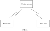
- a master node transmits an Ethernet frame to a slave node through a wireless network
- the slave node receives the Ethernet frame through the wireless network and may send an Ethernet frame to the master node through the wireless network. Therefore, the Ethernet frame needs to be transmitted in the wireless network.
- the Ethernet frame includes a header and a payload, and transmission of the Ethernet frame in the wireless network requires high resource overheads. In the embodiments of this application, overheads of transmitting the Ethernet frame in the wireless network are expected to be reduced, to improve resource utilization.
- information transmitted in the wireless network is reduced through Ethernet header compression, thereby reducing resource overheads and improving resource utilization.
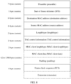
- the Ethernet frame may include the following fields: a 7-byte preamble (preamble), a 1-byte start of frame delimiter (start of frame delimiter, SFD), a 6-byte destination media access control (media access control, MAC) address, a 6-byte source MAC address, a 2-byte length/type (for example, 802.1QTagType), 2-byte tag control information (TAG control information or tagging control information), a 2-byte MAC client length/type, a variable length load or payload, and a 4-byte frame check sequence (frame check sequence, FCS).
- the payload may include data (for example, MAC client data), and optionally, the payload may further include a padding (padding) field.
- Ethernet header Fields before the payload are the Ethernet header, and the subsequent FCS is used for check of the Ethernet frame.
- the foregoing Ethernet format is merely an example, and is not intended to limit this application.
- formats may be different.
- the Ethernet header may include only a destination MAC address, a source MAC address, and a length/type field.
- Other fields may be partially or all included in an Ethernet frame.
- sizes of the foregoing fields are merely an example, and are not used to limit this application.
- the preamble is used to identify and detect that an Ethernet frame is transmitted on an Ethernet transmission link on a receiving side of the Ethernet frame.
- the SFD is used to determine a start position of subsequent Ethernet frame content on the receiving side of the Ethernet frame.
- the compression end may determine the first compression information included in the first correspondence as the first compression information of the Ethernet header of the Ethernet frame.
- Each of correspondences may be associated with an identifier of the correspondence, and the compression information may include the identifier of the correspondence (or referred to as an identifier of the compression information).
- the first compression information includes an identifier of the first correspondence or an identifier of the first compression information.
- the information is a context identifier (context identifier, CID) is used.
- the foregoing provides an example of a to-be-compressed field specified by the profile in the Ethernet protocol.
- a transport layer protocol may be introduced.
- the compression end stores context information, where the context information may include at least one context entry (entry).
- the context information is as follows:
- Step S104 The compression end sends the compressed Ethernet frame to the decompression end.
- the compression end may select an appropriate manner based on an actual application scenario, to send the compressed Ethernet frame to the decompression end. That the compression end sends the compressed Ethernet frame to the decompression end is not specifically limited in this embodiment of this application.
- the compression end sends the compressed Ethernet frame to the decompression end by using a packet data convergence protocol control protocol data unit (packet data convergence protocol data protocol data unit, PDCP data PDU).
- a packet data convergence protocol control protocol data unit packet data convergence protocol data protocol data unit, PDCP data PDU.
- an EHC header may be configured in a format of the PDCP data PDU.
- FIG. 9 shows a format of a PDCP data PDU configured with an EHC header according to an embodiment of this application.
- the format of the PDCP data PDU includes a PDCP header, a service data adaptation protocol (service data adaptation protocol, SDAP) header, the EHC header, an Ethernet data payload (Ethernet data payload), and a message authentication code for integrity (message authentication code for integrity, MAC-I), where the PDCP header includes a PDCP serial number (serial number, SN), and PDCP SNs may be set in different rows.
- service data adaptation protocol service data adaptation protocol
- SDAP service data adaptation protocol
- Ethernet data payload Ethernet data payload
- message authentication code for integrity messages authentication code for integrity
- FIG. 9 shows only one manner of locations of the PDCP header, the SDAP header, the EHC header, the Ethernet data payload, and the MAC-I.
- locations, specific byte lengths, and included content of the PDCP header, the SDAP header, the EHC header, the Ethernet data payload, and the MAC-I may be adaptively set based on an actual application scenario. This is not specifically limited in this embodiment of this application.
- a length of the PDCP SN may be 12 bits or 18 bits.
- the SDAP header may be located between the EHC header and the Ethernet data payload, the SDAP header may be located between the Ethernet data payload and the MAC-I, or the SDAP header may be located after the MAC-I.
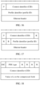
- the EHC header may include an indication field F, a CID, and the Ethernet header.
- the indication field F is used to indicate whether the EHC header includes a complete or compressed Ethernet header, or is used to indicate whether the Ethernet header is compressed.
- FIG. 10 shows a format of an EHC header according to an embodiment of this application.
- a length of the indication field F may be 1 to 3 bits.
- a length of F may be 1 bit, and a value may be 1 or 0.
- the decompression end may determine, based on the value of the field F, whether the data packet carries the compressed Ethernet frame. In this step, the compression end sends the compressed Ethernet frame to the decompression end.
- the value of the field F indicates that the EHC header includes the compressed Ethernet header or indicates whether the Ethernet header is compressed.
- a length value of a context identifier (context ID/CID) field may be 2 to 16 bits.
- a length of the context ID field may be 5 bits, 6 bits, 7 bits, 8 bits, or 16 bits.
- This field indicates an identifier of compression information used for header compression of the Ethernet frame.
- An Ethernet header field is a part obtained after the first to-be-compressed field is removed from an original Ethernet header.
- a sequence of the foregoing fields may be that the field F is located before the CID field, and the CID field is located before the Ethernet header field; or the CID field is located before the field F, and the field F is located before the Ethernet header field. That is, the sequence of these fields is not limited in this embodiment of this application.
- the EHC may further include one or more reserved (R) bits, for example, at least one of a location before the field F, a location between the field F and the CID field, and a location between the CID field and the Ethernet header has at least one reserved bit/R bit.
- R reserved
- the length of the field F is 1 bit
- the length of the CID field is 5 bits
- two reserved bits are located after the CID field.
- the EHC header may further include a profile ID, and a location of the profile ID may be located between the CID and the Ethernet header. This is not specifically limited in this embodiment of this application.
- the foregoing indication field F may be further used to indicate whether a first EHC header includes the profile ID.
- a new indication field may be added to the EHC header, to indicate whether a first EHC header includes the profile ID.
- the correspondence stored by the decompression end may include the profile ID or the default profile may be used, in an optional implementation of this embodiment of this application, it may be further set that the EHC header of the compressed Ethernet frame does not include the profile ID. Therefore, space occupied by the compressed Ethernet frame can be further reduced, and resource occupation can be further reduced.
- Step S105 The decompression end receives the Ethernet frame, where the Ethernet frame includes an identifier of a first correspondence, that is, a first CID.
- specific content of the first correspondence may be the same as specific content of the first correspondence at the compression end.
- a value of a field corresponding to the first compression information in the first correspondence is referred to as the value of the first to-be-decompressed field.
- the first compression information is the same as that in the foregoing descriptions of the compression end, and may also be referred to as first decompression information at the decompression end.
- Content included in the first compression information is the same as that in the foregoing descriptions of the compression end.
- the decompression end may store a correspondence between compression information and a value of a to-be-decompressed field, where the first correspondence is the correspondence between the first compression information and the value of the first to-be-decompressed field.
- a correspondence stored by the decompression end may include the first correspondence, that is, the first correspondence may be prestored at the decompression end.
- a correspondence stored by the decompression end may not include the first correspondence.
- the first correspondence may also be received by the decompression end in real time or from the compression end during data stream transmission.
- a manner of obtaining the first correspondence by the decompression end is not specifically limited in this embodiment of this application.
- a method used by the decompression end to obtain the first correspondence may be determined based on an actual application scenario. The method used by the decompression end to obtain the first correspondence is further described in subsequent embodiments. Details are not described herein in this embodiment of this application.
- the decompression end may determine a value of a to-be-decompressed field included in the first correspondence as the value of the first to-be-decompressed field of the Ethernet header of the Ethernet frame.
- Each of correspondences may be associated with an identifier of the correspondence, and the compression information may include the identifier of the correspondence.
- the first compression information includes the identifier of the first correspondence.
- the compression information may further include a profile identifier, so that the first compression information may further include a first profile ID.
- the profile ID may be used to identify a profile.
- the profile is used to specify a compression mechanism, for example, the profile is used to indicate a compressible field and/or a compression manner. Different profiles are distinguished by using profile IDs. Alternatively, it may be understood as that the profile ID is used to indicate a communication protocol of the Ethernet header and/or a to-be-compressed field of the Ethernet header.
- the compression information may not include a profile ID. For detailed descriptions, refer to the descriptions of the compression side. Details are not described herein again.
- the decompression end may further store an indication variable of each correspondence, and the indication variable is used to indicate whether compression information of the correspondence is used for compression.
- the decompression end may store context information, where the context information may include at least one context entry (entry).
- the context information may include at least one context entry (entry).
- the descriptions of the context information are the same as those in the foregoing embodiment, and details are not described herein again.
- decompression end has the same understanding of a compression mechanism as the compression end, "compression” in the descriptions of the decompression end may be replaced with “decompression”.
- Step S107 The decompression end decompresses the Ethernet header of the Ethernet frame based on the first compression information and the value of the first to-be-decompressed field.
- the decompression end may decompress the Ethernet header by using a process opposite to that of the compression end.
- the decompression end determines, based on the first CID, the first correspondence of the first CID, to find the value of the first to-be-decompressed field. If the first correspondence or the first compression information includes the profile ID, a profile may be determined based on the profile ID, and the first to-be-decompressed field is found based on a compressed field specified by the profile. If the first correspondence does not include the profile ID, the first to-be-decompressed field may be found based on a compressed field specified by the default profile.
- the first to-be-decompressed field may be one or more fields in the Ethernet header, and a specific field or specific fields that is/are specifically included may be determined based on the profile.
- the first to-be-decompressed field is one field in the Ethernet header
- the value of the first to-be-decompressed field in the first correspondence is filled into the field in the Ethernet header, to decompress the Ethernet header in the to-be-decompressed Ethernet frame.
- the value of the first to-be-decompressed field in the first correspondence is split into values of the plurality of fields based on sizes of the plurality of fields, and the values are respectively filled into the plurality of fields, to decompress the Ethernet header of the to-be-decompressed Ethernet frame.
- the first to-be-decompressed field includes a plurality of fields in the Ethernet header, for example, includes a destination MAC address, a source MAC address, and a MAC client length/type.
- the decompression end After determining a specific value of the first to-be-decompressed field based on the first CID, when recovering an original Ethernet header, the decompression end fills a value of a corresponding field into a corresponding Ethernet header field. For example, the decompression end fills a value of the destination MAC address into a destination MAC address field location, fills a value of the source MAC address into a source MAC address field location, and fills a value of the MAC client length/type into a MAC client length/type field location. It may be understood that during actual application, decompression may alternatively be performed based on an actual application scenario by using a decompression manner corresponding to a compression manner of the compression end. This is not specifically limited in this embodiment of this application.
- the compression end may compress the Ethernet header of the Ethernet frame based on the first correspondence including the first compression information and the value of the first to-be-compressed field and the first compression information.
- the decompression end may decompress the Ethernet header of the compressed Ethernet frame based on the first correspondence when receiving the compressed Ethernet frame.
- the first correspondence in this embodiment of this application may be generated by the compression end, and is synchronized with the decompression end. After the decompression end completes synchronization of the first correspondence, the decompression end and the compression end may perform corresponding compression and decompression operations based on the first correspondence.
- FIG. 12 is a schematic flowchart of a method for synchronizing a first correspondence between a compression end and a decompression end according to an embodiment of this application. As shown in FIG. 12 , the method provided in this embodiment of this application includes the following steps.
- Step S201 A compression end generates a first correspondence.
- the compression end may generate the first correspondence based on a to-be-compressed field included in the received Ethernet frame.
- the Ethernet frame received by the compression end may be the same as or different from the Ethernet frame in the embodiment corresponding to FIG. 7 , and a value of the to-be-compressed field in the Ethernet header of the Ethernet frame in this embodiment of this application is same as the value of the first to-be-compressed field in the embodiment corresponding to FIG. 7 .
- the to-be-compressed field is the same as that in the descriptions in the foregoing embodiment, and may be one or more fields in the Ethernet header.
- the compression end may alternatively generate the first correspondence based on one or more of the following fields: a destination MAC address, a source MAC address, a length/type field, TAG control information, a MAC client length/type, and the like.
- a specific manner of generating the first correspondence is not limited in this embodiment of this application.
- the compression end may store a pre-generated correspondence, where the correspondence includes a correspondence between compression information and a value of a to-be-compressed field.
- the compression end receives the Ethernet frame including the first to-be-compressed field
- the compression end generates the first correspondence, where the first correspondence may include a CID and the value of the first to-be-compressed field.
- the correspondence may be stored in a context information manner, and details are not described herein again.
- a value of the first to-be-compressed field is a value of the field.
- a value of the first to-be-compressed field is a combination of values of the plurality of fields, and a length of a value of each field may be specified by a profile.
- a combination manner of the values of the plurality of fields may be determined based on the profile. For example, if a location relationship of the fields is specified in the profile, combination may be performed based on a location sequence of the fields. This is not specifically limited in this embodiment of this application.
- the compression end currently stores a correspondence including a CID 1 and a CID 2, a value of a to-be-compressed field of the CID 1 is A, and a value of a to-be-compressed field of the CID 2 is B.
- a value of a to-be-compressed field of an Ethernet header is C
- a matching item of C cannot be found in the currently stored correspondence
- the compression end allocates a new CID, for example, a CID 3, to the first to-be-compressed field.
- the compression information further includes a profile ID.
- the compression end and the decompression end may determine the profile as a default profile, and perform compression or decompression based on the profile when performing compression or decompression.
- the compression information may not include the profile ID.
- Step S202 The compression end sends the first correspondence to the decompression end.
- the compression end may send the first correspondence to the decompression end in an appropriate manner based on an actual application scenario. This is not specifically limited in this embodiment of this application.
- the compression end sends an uncompressed data packet to the decompression end, where the uncompressed data packet includes the first correspondence.
- the compression end may use the first correspondence and the received Ethernet frame as an uncompressed data packet for sending to the decompression end.
- the compression end may send the uncompressed data packet to the decompression end by using a PDCP data PDU.
- the compression end may send the first correspondence to the decompression end by using a packet data convergence protocol control protocol data unit PDCP control PDU, and send an Ethernet frame data packet to the decompression end by using a PDCP data PDU.
- the compression end may send the first correspondence to the decompression end for a plurality of times, and a quantity times threshold may be further correspondingly set for the first correspondence.
- a quantity times threshold may be further correspondingly set for the first correspondence.
- the compression end maintains a sending quantity times variable for the first correspondence.
- An initial value of the variable may be 0.
- the compression end sends the first correspondence once, and then the sending quantity times variable is accumulated by 1.
- a quantity of times of sending the first correspondence to the decompression end by the compression end reaches the quantity times threshold, it may be considered that the decompression end has successfully received the first correspondence. It may be considered that the first correspondence has been synchronized between the compression end and the decompression end, and step S204 may not be performed.
- the quantity times threshold may be predefined in a protocol, or may be a number that is greater than or equal to 1 and is configured by a network device. In a sidelink communication scenario, the quantity times threshold may be determined by the compression end, or configured by another terminal device for the compression end. This is not specifically limited in this embodiment of this application.
- Step S203 The decompression end receives the first correspondence from the compression end.
- the decompression end may receive the first correspondence from the compression end in an appropriate manner based on an actual application scenario.
- a specific receiving manner is not limited in this embodiment of this application.
- the decompression end after the decompression end receives the first correspondence, when the correspondence stored by the decompression end does not include the first compression information, the decompression end stores the first correspondence.
- the decompression end after the decompression end receives the first correspondence, when the correspondence stored by the decompression end includes the first compression information, and a value of a to-be-decompressed field corresponding to the first compression information is different from a value of the first to-be-decompressed field, the decompression end modifies the value of the to-be-decompressed field corresponding to the first compression information to the first to-be-decompressed field.
- the decompression end may also store the correspondence in a context information manner, and details are not described herein again.
- the decompression end may further send the feedback information to the compression end, where the feedback information is used to indicate the receiving status of the first correspondence.
- the receiving status may include a receiving success or a receiving failure. It may be understood that when the receiving status is the receiving success, the compression end and the decompression end may perform corresponding compression and decompression processing based on the first correspondence. When the receiving status is the receiving failure, the compression end and the decompression end cannot perform corresponding compression and decompression processing based on the first correspondence, and the compression end may further resend the first correspondence to the compression end, delete the first correspondence, or the like. This is not specifically limited in this embodiment of this application.
- the feedback information includes the CID, or confirms a PDCP SN of a data packet that carries the first correspondence.
- the compression end may determine, based on the CID or the PDCP SN, a specific correspondence that is unsuccessfully received.
- the feedback information further includes at least one of the following: a profile ID, a first indication field, and a second indication field, where the first indication field is used to indicate that the first correspondence is a newly added correspondence or a modified correspondence at the decompression end, and the second indication field is used to indicate whether the feedback information is a positive feedback or a negative feedback.
- the feedback information includes the CID and the at least one piece of the foregoing information, a specific length of bits occupied by the CID and each piece of information, and a specific location in the feedback information is not limited in this embodiment of this application.
- FIG. 13 shows a schematic diagram of a format of feedback information.
- the feedback information is sent by using a PDCP control PDU, and includes a CID field, a first indication field (AddOrModify), and a second indication field (AckType).
- the first byte is a header of the PDCP control PDU, where a value of a D/C field indicates that the PDCP PDU is a control PDU, and a value of a PDU type (type) indicates that the control PDU is a control PDU used to transmit the feedback information.
- the value of the PDU type may be a value other than '000' and '001', for example, '010' or '011'.
- a length value of the context identifier (context ID/CID) field may be 2 to 16 bits.
- a length of the context ID field may be 5 bits, 6 bits, 7 bits, 8 bits, or 16 bits.
- a length value of the AckType field may be 1 to 4 bits.
- a length of the AckType field is 1 bit and a value is 1 or 0.
- a length value of the AddOrModify field may be 1 to 4 bits.
- a length of the AddOrModify field is 1 bit and a value is 1 or 0.
- a sequence of the foregoing fields may be the CID field, the AckType field, and the AddOrModify field; the AckType field, the CID field, and the AddOrModify field; or the AckType field, the AddOrModify field, and the CID field. This is not limited in this embodiment of this application.
- the control PDU may further have one or more reserved bits.
- the control PDU may further have one or more reserved bits. For example, on the premise of the field sequence shown in FIG. 13 , at least one of a location between the header of the PDCP control PDU and the CID, a location between the CID field and the AckType field, and a location between the AckType field and the AddOrModify field has at least one reserved bit.
- the compression end further stores an indication variable of each correspondence, and the indication variable is used to indicate whether compression information of the corresponding correspondence is used for compression.
- the compression end may further store an indication variable of the correspondence, and the indication variable is used to indicate whether compression information of the correspondence is used for compression.
- a value of the indication variable may include 0 and 1. When the indication variable is 1, it indicates that the first correspondence is used for compression; when the indication variable is 0, it indicates that the first correspondence cannot be used for compression. Alternatively, when the indication variable is 0, it indicates that the first correspondence is used for compression; when the indication variable is 1, it indicates that the first correspondence cannot be used for compression.
- the compression end when the correspondence stored by the compression end includes the first correspondence corresponding to the first to-be-compressed field of the Ethernet frame, and the indication variable of the first correspondence indicates that the compression information of the first correspondence is not used for compression, the compression end sends the first correspondence to the decompression end.
- step S202 for a manner in which the compression end sends the first correspondence to the decompression end, refer to the descriptions in step S202. Details are not described herein again.
- the compression end sets the indication variable to a first value when the compression end determines that the first correspondence is correctly received by the decompression end, where the first value is used to indicate that the compression information is used for compression.
- the compression end may send the first correspondence to the decompression end for N times, where N is a value greater than or equal to 1. In this case, the compression end determines that the first correspondence is correctly received by the decompression end.
- the compression end receives feedback information that is sent by the decompression end and is used to indicate that the first correspondence is correctly received. In this case, the compression end determines that the first correspondence is correctly received by the decompression end.
- a specific manner in which the compression end determines that the first correspondence is correctly received by the decompression end is not limited in this embodiment of this application.
- the first value may be set based on an actual application scenario, for example, may be 1 or 0. This is not specifically limited in this embodiment of this application.
- the indication variable of the first correspondence may be set to a second value, and the second value is used to indicate that the compression information cannot be used for compression.
- the second value may be set based on an actual application scenario, for example, may be 0 or 1. This is not specifically limited in this embodiment of this application.
- this embodiment of this application may further include: sending, by the compression end, second indication information to the decompression end, where the second indication information is used to indicate that the first correspondence is a newly added correspondence or a modified correspondence at the compression end.
- the second indication information may be used to indicate that the first correspondence is the newly added correspondence or the modified correspondence at the compression end.
- a correspondence for compression and decompression may be synchronized between the compression end and the decompression end.
- the Ethernet header may be compressed and decompressed based on the synchronized correspondence, to reduce occupation of communication resources by the Ethernet header.
- step S202 may include: The compression end sends the first correspondence to the decompression end by using the PDCP data PDU, where the PDCP data PDU includes an EHC header, the EHC header includes an indication field, the CID, and the Ethernet header, and the indication field is used to indicate whether the EHC header includes a complete or compressed Ethernet header, or is used to indicate whether the Ethernet header is compressed.
- an indication field F of the EHC header may be used to indicate whether the EHC header includes a complete or compressed Ethernet header, or is used to indicate whether the Ethernet header is compressed.
- a length of the indication field F may be 1 to 3 bits.
- the length of F may be 1 bit, and a value may be 1 or 0.
- the decompression end may determine, based on the value of the field F, whether the data packet carries the complete Ethernet header.
- a length value of a CID field may be 2 to 16 bits.
- a length of the CID field may be 5 bits, 6 bits, 7 bits, 8 bits, or 16 bits.
- This field indicates an identifier corresponding to compression information used for header compression of the Ethernet frame.
- An Ethernet header field is an original Ethernet header and includes a to-be-compressed field and an uncompressed field.
- a sequence of the foregoing fields may be the field F, the CID field, and the Ethernet header; or the CID field, the field F, and the Ethernet header. This is not limited in this embodiment of this application.
- the EHC may further include one or more reserved bits.
- the EHC may further include one or more reserved bits.
- at least one of a location before the field F, a location between the field F and the CID field, and a location between the CID field and the Ethernet header may have at least one reserved bit.
- the length of the F field is 1 bit
- the length of the CID field is 6 bits
- one reserved bit is located between the CID field and the Ethernet header.
- the indication field F is further used to indicate whether a first EHC header includes a profile identifier profile ID.
- the EHC header further includes the profile ID.
- a new indication field may be added to the EHC header, to indicate whether a first EHC header includes the profile ID.
- an indication field F of the EHC header may be used to indicate whether the EHC header includes a complete or compressed Ethernet header and whether the EHC header carries a profile ID.
- a length of the indication field F may be 1 to 3 bits.
- a length of F may be 1 bit, and a value may be 1 or 0.
- the decompression end may determine, based on the value of the field F, that the data packet carries the complete Ethernet header and carries a profile ID field.
- a length value of a CID field may be 2 to 16 bits.
- a length of the CID field may be 5 bits, 6 bits, 7 bits, 8 bits, or 16 bits.
- This field indicates an identifier corresponding to compression information used for header compression of the Ethernet frame.
- a length value of the profile ID field may be 2 to 8 bits.
- a length of the profile ID field may be 4 bits, 5 bits, 6 bits, or 8 bits.
- An Ethernet header field is an original Ethernet header and includes a to-be-compressed field and a to-be-uncompressed field.
- a sequence of the foregoing fields may be the field F, the CID field, the profile ID field, and the Ethernet header; or the CID field, the field F, the profile ID field, and the Ethernet header.
- the EHC may further include one or more reserved bits.
- the EHC may further include one or more reserved bits.
- at least one of a location before the field F, a location between the field F and the CID field, a location between the CID field and the profile ID field, and a location between the profile ID field and the Ethernet header may have at least one reserved bit.
- the length of the F field is 1 bit
- the length of the CID field is 6 bits
- the length of the profile ID is 6 bits
- three reserved bits are located between the CID field and the profile ID.
- the PDCP data PDU further includes a PDCP header, a service data adaptation protocol SDAP header, an Ethernet data payload, and a MAC-I. Similar to the format of the PDCP data PDU in FIG. 9 , details are not described herein again.
- step S202 in a manner in which the first correspondence is sent to the decompression end by using the PDCP control PDU and the Ethernet frame is sent to the decompression end by using the PDCP data PDU, step S202 may include: The compression end sends the first correspondence to the decompression end by using the PDCP control PDU, where the PDCP control PDU includes indication information, the CID, and a value of a compressible field of the Ethernet header, and the indication information is used to indicate that the PDCP control PDU is used for the first correspondence.
- the PDCP control PDU may not include a value of a to-be-compressed field, but the PDCP data PDU is subsequently sent to the decompression end, where the PDCP data PDU carries the Ethernet header, and a value of a to-be-compressed field in the Ethernet header is equal to the value of the to-be-compressed field.
- indication information is a PDU type
- the first byte is a header of the PDCP control PDU, where a value of a D/C field indicates that the PDCP PDU is a control PDU, and a value of the PDU type indicates that the control PDU is a control PDU used to transmit the first correspondence.
- the value of the PDU type may be a value other than '000' and '001', for example, '010' or '011'.
- a length value of a CID field may be 2 to 16 bits.
- a length of the CID field may be 5 bits, 6 bits, 7 bits, 8 bits, or 16 bits.
- This field indicates an identifier corresponding to compression information used for header compression of the Ethernet frame.
- a value of a to-be-compressed field is a value of a first to-be-compressed field in a first relationship corresponding to the CID field, that is, only a specific value of the to-be-compressed field in the Ethernet header is included.
- a sequence of the foregoing fields may be the CID field and the value of the to-be-compressed field; or the CID field and the value of the to-be-compressed field.
- control PDU may further include one or more reserved bits.
- the control PDU may further include one or more reserved bits.
- the PDCP control PDU further includes the profile ID.
- the PDCP control PDU further includes a profile ID, where a value of a D/C field indicates that the PDCP PDU is a control PDU, and a value of a PDU type indicates that the control PDU is a control PDU used to transmit the first correspondence.
- the value of the PDU type may be a value other than '000' and '001', for example, '010' or '011'.
- a length value of a context identifier (context ID/CID) field may be 2 to 16 bits.
- a length of the context ID field may be 5 bits, 6 bits, 7 bits, 8 bits, or 16 bits.
- a length value of a profile identifier (profile ID) field may be 2 to 8 bits.
- a length of the profile ID field may be 4 bits, 5 bits, 6 bits, or 8 bits.
- a value of a to-be-compressed field is a value of a first to-be-compressed field in a first relationship corresponding to the CID field, that is, only a specific value of the to-be-compressed field is included.
- a sequence of the foregoing fields may be the CID field, the profile ID field, and the value of the to-be-compressed field; or the profile ID field, the CID field, and the value of the to-be-compressed field. That is, the sequence of these fields is not limited in this embodiment of this application.
- the control PDU may further include one or more reserved bits.
- the control PDU may further include one or more reserved bits.
- at least one of a location between a header of the control PDU and the CID field, a location between the CID field and the profile ID field, and a location between the profile ID field and the value of the to-be-compressed field may have at least one reserved bit.
- the length of the CID field is 8 bits
- the length of the profile ID is 7 bits
- the compression end further sends a PDCP data PDU to the decompression end, where the PDCP data PDU includes an EHC header, the EHC header carries an indication field, and the Ethernet header, and the indication field is used to indicate whether the EHC header carries a CID.
- a length of the indication field F may be 1 to 3 bits.
- a length of F may be 1 bit, and a value may be 1 or 0.
- the compression end sends the uncompressed Ethernet frame to the decompression end. Therefore, the value of the field F indicates that the EHC header includes the compressed Ethernet header or indicates whether the Ethernet header is compressed.
- Ethernet header field is an original Ethernet header or a compressed Ethernet header obtained after the to-be-compressed field is removed is indicated by the indication field F.
- the Ethernet header is the compressed Ethernet header; or when the EHC header does not carry the CID, the Ethernet header is the complete Ethernet header.
- a format of the EHC header may be that shown in FIG. 23 .
- a length value of a context identifier (context ID/CID) field may be 2 to 16 bits.
- a length of the context ID field may be 5 bits, 6 bits, 7 bits, 8 bits, or 16 bits. This field indicates an identifier corresponding to compression information used for header compression of the Ethernet frame.
- the decompression end may ignore a specific value of the CID field, or the EHC header does not include the CID field. In this case, to ensure byte alignment of the EHC header, an extra bit location may be filled with a reserved bit.
- Ethernet header field is the original Ethernet header or the compressed Ethernet header obtained after the first to-be-compressed field is removed is indicated by the indication field F.
- a sequence of the foregoing fields may be that the field F is located before the CID field, and the CID field is located before the Ethernet header field; or the CID field is located before the field F, and the field F is located before the Ethernet header field. That is, the sequence of these fields is not limited in this embodiment of this application.
- the EHC may further include one or more reserved bits, for example, at least one of a location before the field F, a location between the field F and the CID field, and a location between the CID field and the Ethernet header has at least one reserved bit.
- the first PDCP data PDU further includes a PDCP header, a service data adaptation protocol SDAP header, an Ethernet data payload, and a MAC-I. Similar to the format of the PDCP data PDU in FIG. 9 , details are not described herein again.
- a check process may further be set to improve a correct rate of compression and decompression. Therefore, in step S104, the EHC header of the PDCP data PDU used to send the compressed Ethernet frame to the decompression end further includes check information.
- FIG. 24 is a schematic diagram of a format of an EHC header including a check code.
- the check code may be located between a profile ID and an Ethernet header. It may be understood that when the EHC header does not include the profile ID, the check code may be located between a CID and the Ethernet header. Alternatively, the check code may be located after the Ethernet header, or between a field F and the CID. That is, a sequence of these fields is not limited in this embodiment of this application. During specific application, to align bytes of the EHC header, one or more reserved bits may alternatively be corresponding added to the EHC header. This is not specifically limited in this embodiment of this application.
- the check information is generated based on one or more pieces of information in the first correspondence.
- the check information may be a cyclic redundancy check (cyclic redundancy check, CRC) or may be a checksum (checksum).
- CRC cyclic redundancy check
- checksum checksum
- the compression end after receiving an Ethernet frame, the compression end generates first check information CRC 1 of X (where X may be determined based on actual application) bits by using a specific polynomial based on one or more of a corresponding compressed field value in a to-be-used correspondence, a complete CID, a complete profile ID, an original Ethernet header, and the like as input.
- the decompression end may also determine a to-be-used correspondence for decompression based on a CID and/or a profile ID in an EHC header, and generate second check information CRC 2 of X bits by using a generation polynomial that is the same as that of the compression end based on one or more of a corresponding compressed field value in the correspondence, the complete CID, the complete profile ID, a decompressed Ethernet header, and the like as input. If the CRC 2 is not equal to the CRC 1 , it is determined that the decompression fails. Alternatively, if the decompression end cannot find context information corresponding to the CID, it is also determined that the decompression fails.
- the compression end after receiving an Ethernet frame, the compression end generates first check information checksum 1 of X (where X may be determined based on actual application) bits by using a specific checksum algorithm based on one or more of a corresponding compressed field value in a to-be-used correspondence, a complete CID, a complete profile ID, an original Ethernet header, and the like as input.
- the decompression end may also determine a to-be-used correspondence for decompression based on a CID and/or a profile ID in an EHC header, and generate second check information checksum 2 of X bits by using a checksum algorithm that is the same as that of the compression end based on one or more of a corresponding compressed field value in the correspondence, the complete CID, the complete profile ID, a decompressed Ethernet header, and the like as input. If the checksum, is not equal to the checksum 1 , it is determined that the decompression fails. Alternatively, if the decompression end cannot find context information corresponding to the CID, it is also determined that the decompression fails.
- the decompression end decompresses the Ethernet header of the to-be-decompressed Ethernet frame based on the value of the first to-be-decompressed field when the first check information is the same as the second check information; or the decompression end deletes the first correspondence, and/or the decompression end sends an error report to the compression end when the first check information is different from the second check information.
- the decompression end determines that the check fails, and the decompression end may delete the first correspondence stored by the decompression end, send the error report to the compression end, or delete the first correspondence stored by the decompression end and send the error report to the compression end. This is not specifically limited in this embodiment of this application.
- the error report may be used to indicate that the check fails, and the decompression end cannot decompress the compressed Ethernet frame.
- the error report may carry the CID and/or the profile ID.
- the error report may also carry a CRC 3, where the CRC 3 is generated by using a generation polynomial based on the error report as input.
- the compression end when the compression end receives the error report returned by the decompression end based on the check information, the compression end may delete the first correspondence, or the compression end sets the first correspondence to being unavailable.
- the compression end may set an indication variable corresponding to the first correspondence to a second value, to indicate that the first correspondence is unavailable.
- the quantity of sending times may be set to an initial value.
- the initial value may be 0.
- the decompression end when determining a check error, may clear all correspondences stored by the decompression end, and feed back an error report to the compression end, where the error report does not carry the CID or the profile ID.
- the compression end may clear all correspondences, or set all correspondences to being unavailable. If the correspondence further corresponds to a quantity of sending times, the quantity of sending times is set to an initial value (for example, 0).
- a check mechanism is introduced, to avoid an error in decompressing a data packet due to inconsistent correspondences stored by the compression end and the decompression end, and improve a correct rate of compression and decompression.
- the compression end and the decompression end in this embodiment of this application may be further preconfigured with a capability of performing EHC.
- the compression end is a terminal
- the decompression end is a network device
- the method further includes: sending, by the compression end, capability information to the decompression end, where the capability information includes at least one of the following: a capability of the compression end supporting EHC, a quantity of data radio bearers (data radio bearers, DRBs) supporting the EHC at the compression end, profile profile information supported by the compression end, a maximum value MAX_CID of entries of correspondences supported by each DRB supporting the EHC, a capability of the compression end supporting dynamic configuration of a profile parameter, and a sum of entries of correspondences maintained by DRBs supporting the EHC at the compression end.
- the capability information includes at least one of the following: a capability of the compression end supporting EHC, a quantity of data radio bearers (data radio bearers, DRBs) supporting the EHC at the compression end, profile profile information supported by the compression
- the capability of the compression end supporting the EHC may specifically include a capability of the compression end supporting uplink EHC, and/or a capability of the compression end supporting downlink EHC.
- the quantity of DRBs supporting the EHC at the compression end is used to indicate a maximum quantity of DRBs that can be configured at the compression end to perform an EHC operation.
- a maximum quantity of DRBs supporting the EHC at the compression end may be specified in a protocol, or it indicates that the quantity of DRBs supporting the EHC at the compression end is not limited.
- the profile profile information supported by the compression end may specifically include uplink profile information supported by the compression end, and/or downlink profile information supported by the compression end that may be used to indicate specific profiles corresponding to Ethernet protocol frames on which the compression end can perform EHC processing. If the information is not indicated, it indicates that the compression end supports EHC processing on Ethernet protocol frames corresponding to all profiles defined in a protocol.
- Other capabilities for example, a quantity MAX_CID supported by one DRB, and a total quantity of supported CIDs may be separately indicated in terms of an uplink and/or a downlink.
- the MAX_CID supported by one DRB may be specified in the protocol, or it indicates that there is no limitation.
- the compression end does not indicate information about the capability of the compression end supporting the dynamic configuration of the profile parameter, it indicates that the compression end supports/does support the network device in dynamically configure the profile parameter.
- a specific memory is required to store the correspondence. From a perspective of the terminal device, a supported memory is limited. Therefore, a memory that can be used to store the correspondence may also be limited.
- a total quantity of correspondences supported by the compression end may be specified in the protocol, or it indicates that there is no limitation.
- the capability information may further include a capability of the compression end supporting processing of feedback information of the decompression end.
- the compression end does not indicate the information, it indicates that the compression end supports/does support processing of the feedback information.
- the capability information may further include a capability of the compression end supporting sending of the first correspondence for a plurality of times. When the compression end does not indicate the information, it indicates that the compression end supports/does support sending of the first correspondence for the plurality of times.
- the compression end may send the capability information to the decompression end by using a radio resource control (radio resource control, RRC) message, or may send the capability information to the decompression end in another manner.
- RRC radio resource control
- the decompression end may configure, for the compression end, at least one of the following: information about a DRB or a packet data convergence protocol PDCP entity supporting the uplink EHC, information about a DRB or a PDCP entity supporting the downlink EHC, profile information supported by the DRB or the PDCP entity supporting the uplink EHC, profile information supported by the DRB or the PDCP entity supporting the downlink EHC, a maximum value of entries of compression context information used when each DRB or PDCP entity performs an EHC operation, a sum of entries of compression context information maintained by a DRB supporting the EHC at the compression end, a feedback operation performed for the EHC, a plurality of sending operations of sending the first correspondence that are performed for the EHC, and a threshold of sending times used when the first correspondence is sent for a plurality of times.
- the decompression end may configure the foregoing content for the compression end by using RRC signaling.
- the MAX_CID when the MAX_CID is configured at the compression end, if it is found that entries of previously stored correspondences have reached the MAX_CID, no new correspondence is established for a subsequent data packet, and only an existing correspondence is used to compress the data packet. If a correspondence cannot be found for a new arrival data packet, compression processing is not performed. For example, if CIDs at the compression end are used up, compression processing may not be performed on the subsequent data packet, and the first correspondence is also not carried when the data packet is sent, or the terminal may not perform compression processing on a part of data packets based on the implementation. In this case, there may be two considerations for an encapsulation format of the data packet.
- the compression end receives the data packet, and may determine, based on the value of the field F and the reserved value of the CID, that the data packet is the uncompressed data packet and does not carry the first correspondence.
- the compression end receives the data packet, and may determine, based on the value of the field F and the reserved value of the CID and/or the reserved value of the profile ID, that the data packet is the uncompressed data packet and does not carry the first correspondence.
- the compression end when the MAX_CID is configured at the compression end, if it is found that entries of previously stored correspondences have reached the MAX_CID, the compression end still generates the first correspondence, and may replace any entry of the previously stored correspondences with the first correspondence, to store the first correspondence.
- the any entry may be randomly selected by the compression end or determined in another manner. This is not limited in this embodiment of this application.
- the method further includes: receiving, by the terminal, configuration information, where the configuration information is further used to indicate whether the EHC header carries the profile ID, or the configuration information further includes the profile ID and the EHC header does not include the profile ID.
- an EHC header of a data packet of the DRB does not carry the profile ID; when RRC is not used to configure that one DRB supports only one profile, an EHC header needs to carry the profile ID.
- the terminal may receive the configuration information sent by the network device by using the RRC, and the RRC may indicate, by using a specific field, whether the EHC header carries the profile ID.
- a presence of profile ID field may be used to indicate whether the EHC header carries the profile ID. For example, if the presence of profile ID field is carried in a PDCP configuration information element, it indicates that the EHC header carries the profile ID; if the presence of profile ID field is not carried, the EHC header does not carry the profile ID.
- a value of the presence of profile ID may be further set to 1 or 0, where 1 indicates that the EHC header carries the profile ID, and 0 indicates that the EHC header does not carry the profile ID. Alternatively, 0 indicates that the EHC header carries the profile ID, and 1 indicates that the EHC header does not carry the profile ID.
- a presence of profile ID field may be further separately configured for an uplink EHC operation and a downlink EHC operation of the terminal, to indicate whether an uplink EHC header and a downlink EHC header each carry a profile ID.
- a presence of profile ID-UL field is configured to indicate whether the uplink EHC header carries the profile ID
- a presence of profile ID-DL field is configured to indicate whether the downlink EHC header carries the profile ID.
- a value of the presence of profile ID-UL may be set to 1 or 0, where 1 indicates that the uplink EHC header carries the profile ID, and 0 indicates that the uplink EHC header does not carry the profile ID; or 0 indicates that the uplink EHC header carries the profile ID, and 1 indicates that the uplink EHC header does not carry the profile ID.
- a value of the presence of profile ID-DL is 1 or 0, where 1 indicates that the downlink EHC header carries the profile ID, and 0 indicates that the downlink EHC header does not carry the profile ID; or 0 indicates that the downlink EHC header carries the profile ID, and 1 indicates that the downlink EHC header does not carry the profile ID. Values of the fields are not specifically limited in this embodiment of this application.
- whether an EHC data packet of the DRB carries the profile ID field may be implicitly determined based on a quantity, configured by using the RRC, of profiles supported by the DRB. For example, if the quantity, configured by using the RRC, of profiles supported by the DRB is 1, it may be considered that it indicates that the profile ID is not carried. If the quantity, configured by using the RRC, of profiles supported by the DRB is a value greater than 1, it may be considered that it indicates that the profile ID is carried.
- the profile ID of the terminal may be configured by using the configuration information, so that the EHC header may not include the profile ID, to reduce a size of the EHC header and reduce occupation of communication resources.
- the compression end is a network device
- the decompression end is a terminal
- the method further includes: receiving, by the compression end, capability information, where the capability information includes at least one of the following: a capability of the decompression end supporting EHC, a quantity of data radio bearers DRBs supporting the EHC at the decompression end, profile profile information supported by the decompression end, a maximum value MAX_CID of entries of correspondences supported by each DRB supporting the EHC, a capability of the decompression end supporting dynamic configuration of a profile parameter, and a sum of entries of correspondences maintained by DRBs supporting the EHC at the decompression end.
- the capability information includes at least one of the following: a capability of the decompression end supporting EHC, a quantity of data radio bearers DRBs supporting the EHC at the decompression end, profile profile information supported by the decompression end, a maximum value MAX_CID of entries of correspondences supported by each DRB supporting the EHC, a capability of the decompression end supporting
- the compression end may correspondingly configure, for the decompression end, at least one of the following: information about a DRB or a packet data convergence protocol PDCP entity supporting the uplink EHC, information about a DRB or a PDCP entity supporting the downlink EHC, profile information supported by the DRB or the PDCP entity supporting the uplink EHC, profile information supported by the DRB or the PDCP entity supporting the downlink EHC, a maximum value of entries of compression context information used when each DRB or PDCP entity performs an EHC operation, and a sum of entries of compression context information maintained by a DRB supporting the EHC at the compression end.
- the compression end may configure the foregoing content for the decompression end by using RRC signaling.
- the method further includes: sending, by the network device, configuration information to the terminal, where the configuration information is further used to indicate whether the EHC header carries a profile ID, or the configuration information further includes a profile ID and the EHC header does not include the profile ID.
- the two terminals may exchange a capability of supporting EHC by using sidelink messages, for example, the two terminals directly exchange an EHC capability of a sidelink interface by using sidelink RRC messages, or the two terminals exchange an EHC capability of a sidelink interface through a base station or another terminal.
- the compression end may receive the capability information of the decompression end by using a sidelink message, or receive the capability information of the decompression end through the base station or the another terminal. This is not specifically limited in this embodiment of this application.
- the decompression end may also receive the capability information of the compression end, to exchange the capability information between the decompression end and the compression end. Details are not described herein again.
- the compression end and the decompression end may further exchange configuration information, where the configuration information is further used to indicate whether the EHC header carries the profile ID, or the configuration information further includes the profile ID and the EHC header does not include the profile ID. Details are not described herein again.
- the compression end or the decompression end may be handed over.
- the compression end when the compression end is a terminal, and the decompression end is a network device, the compression end may be handed over to different network devices.
- a decompression end that initially communicates with the compression end may be referred as a source station, and a decompression end to which the compression end is to be handed over for communication may be referred to as a target station.
- the source station may deliver a correspondence of a part or all of DRBs in the source station to the target station by using a handover request (handover request, HR) message.
- handover request handover request
- the target station may configure EHC continue (continue) for a part or all of DRBs at the compression end.
- the compression end does not need to clear a correspondence of a corresponding DRB, and may continue to perform an EHC operation by using an original correspondence, to reduce a quantity of times of generating the correspondence by the compression end and reduce occupation of computing resources.
- the target station may not configure EHC continue for a part or all of DRBs at the compression end. In this case, the compression end may clear a correspondence of a corresponding DRB, to reduce occupation of storage space.
- An embodiment of this application further provides an apparatus configured to implement any one of the foregoing methods.
- an apparatus is provided, and includes units (or means) configured to implement the steps performed by the terminal in any one of the foregoing methods.
- another apparatus is further provided, and includes units (or means) configured to implement the steps performed by the access network device in any one of the foregoing methods.
- another apparatus is further provided, and includes units (or means) configured to implement the steps performed by the core network device in any one of the foregoing methods.
- FIG. 25 is a schematic diagram of an Ethernet header compression apparatus according to an embodiment of this application.
- the apparatus is used at a compression end.
- the apparatus 2500 includes a receiving unit 2510, a determining unit 2520, and a compression unit 2530.
- the receiving unit 2510 is configured to receive a first Ethernet frame, where an Ethernet header of the first Ethernet frame includes a first to-be-compressed field.
- the determining unit 2520 is configured to determine first compression information of the Ethernet header of the first Ethernet frame based on a first correspondence and the first to-be-compressed field, where the first correspondence includes a correspondence between the first compression information and a value of the first to-be-compressed field, and the first compression information includes a first context identifier CID.
- the compression unit 2530 is configured to compress the Ethernet header of the first Ethernet frame based on the first compression information.
- the apparatus 1700 may further include a first relationship generation unit, configured to generate the first correspondence when a correspondence stored by the compression end does not include the value of the first to-be-compressed field of the first Ethernet frame, where the correspondence stored by the compression end includes a correspondence between at least one piece of compression information and a value of a to-be-compressed field.
- a first relationship generation unit configured to generate the first correspondence when a correspondence stored by the compression end does not include the value of the first to-be-compressed field of the first Ethernet frame, where the correspondence stored by the compression end includes a correspondence between at least one piece of compression information and a value of a to-be-compressed field.
- the apparatus further includes a sending unit, configured to send the first correspondence to a decompression end.
- the sending unit is specifically configured to send an uncompressed data packet to the decompression end, where the uncompressed data packet includes the first correspondence.
- the sending unit is further specifically configured to send the first correspondence to the decompression end by using a first packet data convergence protocol data protocol data unit PDCP data PDU, where the first PDCP data PDU includes a first Ethernet header compression EHC header, the first EHC header includes a first indication field, the first CID, and an Ethernet header of a second Ethernet frame, a value of a to-be-compressed field in the Ethernet header of the second Ethernet frame is equal to the value of the first to-be-compressed field, and the first indication field is used to indicate whether the first EHC header includes a complete Ethernet header.
- PDCP data PDU includes a first Ethernet header compression EHC header
- the first EHC header includes a first indication field, the first CID, and an Ethernet header of a second Ethernet frame
- a value of a to-be-compressed field in the Ethernet header of the second Ethernet frame is equal to the value of the first to-be-compressed field
- the first indication field is used to indicate whether the first EHC header includes a complete Ethernet header
- the first EHC header further includes a first profile identifier profile ID.
- the first indication field is further used to indicate that the first EHC header includes the first profile ID.
- the first PDCP data PDU further includes a PDCP header, a service data adaptation protocol SDAP header, an Ethernet data payload, and a message authentication code for integrity MAC-I.
- the sending unit is further specifically configured to send the first correspondence to the decompression end by using a packet data convergence protocol control protocol data unit PDCP control PDU, where the PDCP control PDU includes first indication information, the first CID, and the value of the first to-be-compressed field, and the first indication information is used to indicate that the PDCP control PDU is used to transmit the first correspondence.
- PDCP control PDU includes first indication information, the first CID, and the value of the first to-be-compressed field, and the first indication information is used to indicate that the PDCP control PDU is used to transmit the first correspondence.
- the PDCP control PDU further includes a profile ID.
- the sending unit is further specifically configured to send a first PDCP data PDU to the decompression end, where the first PDCP data PDU includes a first EHC header, the first EHC header includes a first indication field and an Ethernet header of a second Ethernet frame, a value of a to-be-compressed field in the Ethernet header of the second Ethernet frame is equal to the value of the first to-be-compressed field, and the first indication field is used to indicate whether the first EHC header carries the first CID.
- the Ethernet header of the second Ethernet frame is a compressed Ethernet header; or when the first EHC header does not carry the first CID, the Ethernet header of the second Ethernet frame is a complete Ethernet header.
- the first PDCP data PDU further includes a PDCP header, a service data adaptation protocol SDAP header, an Ethernet data payload, and a message authentication code for integrity MAC-I.
- the sending unit is further specifically configured to send the first correspondence to the decompression end for a plurality of times.
- the receiving unit is further configured to receive feedback information from the decompression end, where the feedback information is used to indicate a receiving status of the first correspondence.
- the feedback information includes the first CID.
- the feedback information further includes at least one of the following: the first profile ID, a second indication field, and a third indication field, the second indication field is used to indicate that the first correspondence is a newly added correspondence or a modified correspondence at the decompression end, and the third indication field is used to indicate that the feedback information is a positive feedback or a negative feedback.
- the compression end further stores an indication variable of the correspondence, and the indication variable is used to indicate whether compression information of the correspondence is used for compression.
- the sending unit is further configured to send the first correspondence to a decompression end when a correspondence stored by the compression end includes the first correspondence corresponding to the first to-be-compressed field, and an indication variable of the first correspondence is used to indicate that compression information of the first correspondence is not used for compression.
- the apparatus further includes a variable setting unit, configured to set, by the compression end, the indication variable to a first value when the compression end determines that the first correspondence is correctly received by the decompression end, where the first value is used to indicate that the compression information is used for compression.
- a variable setting unit configured to set, by the compression end, the indication variable to a first value when the compression end determines that the first correspondence is correctly received by the decompression end, where the first value is used to indicate that the compression information is used for compression.
- the first compression information further includes the first profile ID.
- the sending unit is further configured to send second indication information to the decompression end, where the second indication information is used to indicate that the first correspondence is a newly added correspondence or a modified correspondence at the compression end.
- the sending unit is further configured to send a compressed first Ethernet frame to the decompression end, where the compressed first Ethernet frame includes the first CID and does not include a profile identifier profile ID.
- the sending unit is further configured to send a compressed first Ethernet frame to the decompression end includes: The compression end sends the compressed first Ethernet frame to the decompression end by using a second PDCP data PDU.
- the check information is generated based on one or more pieces of information in the first correspondence.
- the apparatus further includes a setting unit, configured to: when the compression end receives an error report returned by the decompression end based on the check information, delete the first correspondence, or set the first correspondence to being unavailable.
- a setting unit configured to: when the compression end receives an error report returned by the decompression end based on the check information, delete the first correspondence, or set the first correspondence to being unavailable.
- the compression end is a terminal
- the decompression end is a network device
- the sending unit is further configured to send capability information to the decompression end
- the capability information includes at least one of the following: a capability of the compression end supporting EHC, a quantity of data radio bearers DRBs supporting the EHC at the compression end, profile profile information supported by the compression end, a maximum value MAX_CID of a quantity of correspondences supported by each DRB supporting the EHC, a capability of the compression end supporting dynamic configuration of a profile parameter, and a sum of quantities of correspondences maintained by DRBs supporting the EHC at the compression end.
- the receiving unit is further configured to receive configuration information, where the configuration information is used to indicate whether an EHC header carries a profile ID, or the configuration information includes a profile ID.
- the compression end is a network device or a terminal
- the receiving unit is further configured to receive capability information
- the capability information includes at least one of the following: a capability of the compression end supporting EHC, a quantity of data radio bearers DRBs supporting the EHC at the compression end, profile profile information supported by the compression end, a maximum value MAX_CID of a quantity of correspondences supported by each DRB supporting the EHC, a capability of the compression end supporting dynamic configuration of a profile parameter, and a sum of quantities of correspondences maintained by DRBs supporting the EHC at the compression end.
- FIG. 26 is a schematic diagram of an Ethernet header decompression apparatus according to an embodiment of this application.
- the apparatus is used at a decompression end.
- the apparatus 2600 includes a receiving unit 2610, a determining unit 2620, and a decompression unit 2630.
- the receiving unit 2610 is configured to receive a first Ethernet frame and a first context identifier CID.
- the determining unit 2620 is configured to determine, based on the first CID, a first correspondence including the first CID, where the first correspondence includes a correspondence between first compression information and a value of a first to-be-decompressed field, and the first compression information includes the first CID.
- the decompression unit 2630 is configured to decompress an Ethernet header of the first Ethernet frame based on the first compression information and the value of the first to-be-decompressed field in the first correspondence.
- the receiving unit is further configured to receive the first correspondence from a compression end.
- the receiving unit is specifically configured to receive an uncompressed data packet, where the uncompressed data packet includes the first correspondence.
- the receiving unit is further configured to receive the first correspondence from the compression end by using a PDCP data PDU, where the first PDCP data PDU includes a first Ethernet header compression EHC header, the first EHC header includes a first indication field, the first CID, and an Ethernet header of a second Ethernet frame, a value of a to-be-compressed field in the Ethernet header of the second Ethernet frame is equal to the value of the first to-be-compressed field, and the first indication field is used to indicate whether the first EHC header includes a complete Ethernet header.
- the first PDCP data PDU includes a first Ethernet header compression EHC header
- the first EHC header includes a first indication field, the first CID, and an Ethernet header of a second Ethernet frame
- a value of a to-be-compressed field in the Ethernet header of the second Ethernet frame is equal to the value of the first to-be-compressed field
- the first indication field is used to indicate whether the first EHC header includes a complete Ethernet header.
- the first EHC header further includes a first profile identifier profile ID.
- the first indication field is further used to indicate that the first EHC header includes the first profile ID.
- the first PDCP data PDU further includes a PDCP header, a service data adaptation protocol SDAP header, an Ethernet data payload, and a message authentication code for integrity MAC-I.
- the receiving unit is further configured to receive the first correspondence sent by the compression end by using a PDCP control PDU, where the PDCP control PDU includes first indication information, a CID, and the value of the first to-be-compressed field, and the first indication information is used to indicate that the PDCP control PDU is used to transmit the first correspondence.
- the PDCP control PDU includes first indication information, a CID, and the value of the first to-be-compressed field, and the first indication information is used to indicate that the PDCP control PDU is used to transmit the first correspondence.
- the PDCP control PDU further includes a first profile ID.
- the receiving unit is further configured to receive a first PDCP data PDU from the compression end, where the first PDCP data PDU includes a first EHC header, the first EHC header includes a first indication field and an Ethernet header of a second Ethernet frame, a value of a to-be-compressed field in the Ethernet header of the second Ethernet frame is equal to the value of the first to-be-compressed field, and the first indication field is used to indicate whether the first EHC header carries the first CID.
- the Ethernet header of the second Ethernet frame is a compressed Ethernet header; or when the first EHC header does not carry the first CID, the Ethernet header of the second Ethernet frame is a complete Ethernet header.
- the first PDCP data PDU further includes a PDCP header, a service data adaptation protocol SDAP header, an Ethernet data payload, and a message authentication code for integrity MAC-I.
- the decompression end stores a correspondence between at least one piece of compression information and a value of a to-be-decompressed field.
- a first correspondence setting unit is further included, and is configured to store the first correspondence when the correspondence stored by the decompression end does not include the first compression information; or modify a value of a to-be-decompressed field corresponding to the first compression information to the value of the first to-be-decompressed field when the correspondence stored by the decompression end includes the first compression information, and the value of the to-be-decompressed field corresponding to the first compression information is different from the value of the first to-be-decompressed field.
- the apparatus further includes a sending unit, configured to send feedback information to the compression end, where the feedback information is used to indicate a receiving status of the first correspondence.
- a sending unit configured to send feedback information to the compression end, where the feedback information is used to indicate a receiving status of the first correspondence.
- the feedback information includes the first CID.
- the feedback information further includes at least one of the following: a profile ID, a first indication field, and a second indication field, the first indication field is used to indicate that the first correspondence is a newly added correspondence or a modified correspondence at the decompression end, and the second indication field is used to indicate that the feedback information is a positive feedback or a negative feedback.
- the first Ethernet frame further includes first check information.
- the first check information is generated based on one or more pieces of information in the first correspondence.
- the apparatus further includes a check unit, configured to: generate second check information based on the one or more pieces of information in the first correspondence; and decompress, by the compression end, the Ethernet header of the first Ethernet frame when the first check information is the same as the second check information; or delete, by the compression end, the first correspondence, and/or send, by the compression end, an error report to the compression end when the first check information is different from the second check information.
- a check unit configured to: generate second check information based on the one or more pieces of information in the first correspondence; and decompress, by the compression end, the Ethernet header of the first Ethernet frame when the first check information is the same as the second check information; or delete, by the compression end, the first correspondence, and/or send, by the compression end, an error report to the compression end when the first check information is different from the second check information.
- division into the units in the foregoing apparatus is merely logical function division. During actual implementation, all or some of the units may be integrated into one physical entity, or may be physically separate.
- all the units in the apparatus may be implemented in a form of software invoked by a processing element, or may be implemented in a form of hardware; or some units may be implemented in a form of software invoked by a processing element, and some units may be implemented in a form of hardware.
- each unit may be a separately disposed processing element, or may be integrated into a chip of the apparatuses for implementation.
- each unit may alternatively be stored in a memory in a form of a program to be invoked by a processing element of the apparatus to perform a function of the unit.
- the processing element herein may also be referred to as a processor, and may be an integrated circuit having a signal processing capability.
- the steps of the foregoing methods or the foregoing units may be implemented by using a hardware integrated logic circuit in the processing element, or may be implemented in a form of software invoked by the processing element.
- a unit in any one of the foregoing apparatuses may be one or more integrated circuits configured to implement the foregoing methods, for example, one or more application-specific integrated circuits (Application Specific Integrated Circuits, ASICs), one or more microprocessors (digital signal processors, DSPs), one or more field programmable gate arrays (Field Programmable Gate Arrays, FPGAs), or a combination of at least two of the integrated circuits.
- the processing element may be a general-purpose processor, for example, a central processing unit (central processing unit, CPU) or another processor that can invoke the program.
- the units may be integrated and implemented in a form of a system-on-a-chip (system-on-a-chip, SOC).
- the foregoing unit for receiving is an interface circuit of the apparatus, configured to receive a signal from another apparatus.
- the receiving unit is an interface circuit that is of the chip and that is configured to receive a signal from another chip or apparatus.
- the foregoing unit for sending is an interface circuit of the apparatus, configured to send a signal to another apparatus.
- the sending unit is an interface circuit that is of the chip and that is configured to send a signal to another chip or apparatus.
- FIG 27 is a schematic diagram of a structure of a network device according to an embodiment of this application.
- the network device is configured to implement operations of the network device in the foregoing embodiments.
- the network device includes an antenna 2710, a radio frequency apparatus 2720, and a baseband apparatus 2730.
- the antenna 2710 is connected to the radio frequency apparatus 2720.
- the radio frequency apparatus 2720 receives, through the antenna 2710, information sent by a terminal apparatus, and sends, to the baseband apparatus 2730 for processing, the information sent by the terminal apparatus.
- the baseband apparatus 2730 processes information of the terminal apparatus, and sends the information to the radio frequency apparatus 2720. After processing the information of the terminal apparatus, the radio frequency apparatus 2720 sends the information to the terminal apparatus through the antenna 2710.
- the baseband apparatus 2730 may include one or more processing elements 2731, for example, includes a master CPU and another integrated circuit.
- the baseband apparatus 2730 may further include a storage element 2732 and an interface 2733.
- the storage element 2732 is configured to store a program and data.
- the interface 2733 is configured to exchange information with the radio frequency apparatus 2720, and the interface is, for example, a common public radio interface (common public radio interface, CPRI).
- the foregoing apparatus used for the network device may be located in the baseband apparatus 2730.
- the foregoing apparatus used for the network device may be a chip on the baseband apparatus 2730.
- the chip includes at least one processing element and interface circuit.
- the processing element is configured to perform the steps of any one of the methods performed by the network device.
- the interface circuit is configured to communicate with another apparatus.
- units of the network device that implement the steps in the foregoing method may be implemented by a program scheduled by a processing element.
- the apparatus used for the network device includes a processing element and a storage element.
- the processing element invokes a program stored in the storage element, to perform the method performed by the network device in the foregoing method embodiments.
- the storage element may be a storage element located on a same chip as the processing element, namely, an on-chip storage element, or may be a storage element located on a different chip from the processing element, namely, an off-chip storage element.
- units of the network device that implement the steps in the foregoing methods may be configured as one or more processing elements. These processing elements are disposed in the baseband apparatus.
- the processing element herein may be an integrated circuit, for example, one or more ASICs, one or more DSPs, one or more FPGAs, or a combination of these types of integrated circuits. These integrated circuits may be integrated together to form a chip.
- Units of the network device that implement the steps in the foregoing methods may be integrated together, and implemented in a form of a system-on-a-chip (system-on-a-chip, SOC).
- the baseband apparatus includes the SOC chip, configured to implement the foregoing methods.
- At least one processing element and a storage element may be integrated into the chip, and the processing element invokes a program stored in the storage element to implement the foregoing methods performed by the network device.
- at least one integrated circuit may be integrated into the chip, to implement the foregoing methods performed by the network device.
- functions of some units may be implemented by a program invoked by the processing element, and functions of some units may be implemented by the integrated circuit.
- the foregoing apparatus used for the network device may include at least one processing element and an interface circuit.
- the at least one processing element is configured to perform any one of the methods that are provided in the foregoing method embodiments and performed by the network device.
- the processing element may perform some or all steps performed by the network device, in a first manner, to be specific, by invoking the program stored in the storage element; or may perform some or all steps performed by the network device, in a second manner, to be specific, by using a hardware integrated logic circuit in the processing element in combination with instructions; or may certainly perform, by combining the first manner and the second manner, some or all steps performed by the network device.
- the processing element herein may be a general-purpose processor, for example, a CPU, or may be one or more integrated circuits configured to implement the foregoing methods, for example, one or more ASICs, one or more microprocessors DSPs, one or more FPGAs, or a combination of at least two of the integrated circuits.
- the storage element may be one memory, or may be a general term of a plurality of storage elements.
- FIG. 28 is a schematic diagram of a structure of a terminal apparatus according to an embodiment of this application.
- the terminal apparatus is configured to implement operations of the terminal in the foregoing embodiments.
- the terminal apparatus includes an antenna 2810, a radio frequency part 2828, and a signal processing part 2830.
- the antenna 2810 is connected to the radio frequency part 2828.
- the radio frequency part 2828 receives, through the antenna 2810, information sent by an access network device, and sends, to the signal processing part 2830 for processing, the information sent by the access network device.
- the signal processing part 2830 processes information of the terminal apparatus, and sends the information to the radio frequency part 2828.
- the radio frequency part 2828 sends the information to the access network device through the antenna 2810.
- the signal processing section 2830 is configured to process data at each communication protocol layer.
- the signal processing part 2830 may be a subsystem of the terminal apparatus, and the terminal apparatus may further include another subsystem.
- a central processing subsystem is configured to process an operating system and an application layer of the terminal apparatus.
- a peripheral subsystem is configured to connect to another device.
- the signal processing part 2830 may be a chip disposed separately.
- the foregoing apparatus may be located in the signal processing part 2830.
- the signal processing part 2830 may include one or more processing elements 2831, for example, includes a master CPU and another integrated circuit.
- the signal processing part 2830 may further include a storage element 2832 and an interface circuit 2833.
- the storage element 2832 is configured to store data and a program, and a program for performing the method performed by the terminal apparatus in the foregoing method may or may not be stored in the storage element 2832, for example, stored in a memory outside the signal processing part 2830.
- the signal processing part 2830 loads the program into a cache for use.
- the interface circuit 2833 is configured to communicate with the apparatus.
- the foregoing apparatus may be located in the signal processing part 2830.
- the signal processing part 2830 may be implemented by using a chip.
- the chip includes at least one processing element and an interface circuit, the processing element is configured to perform steps of any method performed by the foregoing terminal apparatus, and the interface circuit is configured to communicate with another apparatus.
- units that implement the steps in the foregoing method may be implemented by a program scheduled by a processing element.
- the apparatus includes a processing element and a storage element.
- the processing element invokes a program stored in the storage element, to perform the method performed by the terminal apparatus in the foregoing method embodiments.
- the storage element may be a storage element located on a same chip as the processing element, namely, an on-chip storage element.
- the program used to perform the method performed by the terminal apparatus in the foregoing methods may be in a storage element located on a different chip from the processing element, namely, an off-chip storage element.
- the processing element invokes or loads the program from the off-chip storage element to the on-chip storage element, to invoke and perform the method performed by the terminal apparatus in the foregoing method embodiments.
- units of the terminal apparatus may be configured as one or more processing elements. These processing elements are disposed on the signal processing part 2830.
- the processing element herein may be an integrated circuit, for example, one or more ASICs, one or more DSPs, one or more FPGAs, or a combination of these types of integrated circuits. These integrated circuits may be integrated together to form a chip.
- Units that implement the steps in the foregoing methods may be integrated together, and implemented in a form of a system-on-a-chip (system-on-a-chip, SOC).
- SOC system-on-a-chip
- the SOC chip is configured to implement the foregoing methods.
- At least one processing element and a storage element may be integrated into the chip, and the processing element invokes a program stored in the storage element to implement the foregoing methods performed by the terminal apparatus.
- at least one integrated circuit may be integrated into the chip, to implement the foregoing methods performed by the terminal apparatus.
- functions of some units may be implemented by a program invoked by the processing element, and functions of some units may be implemented by the integrated circuit.
- the foregoing apparatus may include at least one processing element and an interface circuit.
- the at least one processing element is configured to perform any one of the methods that are provided in the foregoing method embodiments and performed by the terminal apparatus.
- the processing element may perform some or all steps performed by the terminal apparatus, in a first manner, to be specific, by invoking the program stored in the storage element; or may perform some or all steps performed by the terminal apparatus, in a second manner, to be specific, by using a hardware integrated logic circuit in the processing element in combination with instructions; or may certainly perform, by combining the first manner and the second manner, some or all steps performed by the terminal apparatus.
- the processing element herein may be a general-purpose processor, for example, a CPU, or may be one or more integrated circuits configured to implement the foregoing methods, for example, one or more ASICs, one or more microprocessors DSPs, one or more FPGAs, or a combination of at least two of the integrated circuits.
- the storage element may be one memory, or may be a general term of a plurality of storage elements.
- FIG. 29 is a schematic diagram of a structure of a compression end device according to an embodiment of this application.
- the compression end device is configured to implement operations of the compression end in the foregoing embodiments.
- the compression end device includes a processor 2910, a memory 2920, and an interface 2930.
- the processor 2910, the memory 2920, and the interface 2930 are connected by using signals.
- the method performed by the compression end device in the foregoing embodiment may be implemented by the processor 2910 invoking a program stored in the memory 2920.
- the apparatus used for the compression end device includes a memory and a processor.
- the memory is configured to store a program, and the program is invoked by the processor to perform the method performed by the compression end device in the foregoing method embodiments.
- the processor herein may be an integrated circuit having a signal processing capability, for example, a CPU.
- the apparatus used for the compression end device may be implemented by using one or more integrated circuits configured to implement the foregoing method, for example, one or more ASICs, one or more microprocessors DSPs, one or more FPGAs, or a combination of at least two of the integrated circuits. Alternatively, the foregoing implementations may be combined.
- FIG. 30 is a schematic diagram of a structure of a decompression end device according to an embodiment of this application.
- the decompression end device is configured to implement operations of the decompression end in the foregoing embodiments.
- the decompression end device includes a processor 3010, a memory 3020, and an interface 3030.
- the processor 3010, the memory 3020, and the interface 3030 are connected by using signals.
- the method performed by the decompression end device in the foregoing embodiment may be implemented by the processor 3010 invoking a program stored in the memory 3020.
- the apparatus used for the decompression end device includes a memory and a processor.
- the memory is configured to store a program, and the program is invoked by the processor to perform the method performed by the decompression end device in the foregoing method embodiments.
- the processor herein may be an integrated circuit having a signal processing capability, for example, a CPU.
- the apparatus used for the decompression end device may be implemented by using one or more integrated circuits configured to implement the foregoing method, for example, one or more ASICs, one or more microprocessors DSPs, one or more FPGAs, or a combination of at least two of the integrated circuits. Alternatively, the foregoing implementations may be combined.
- the program may be stored in a computer-readable storage medium.
- the foregoing storage medium includes: any medium that can store program code, such as a ROM, a RAM, a magnetic disk, or an optical disc.
Landscapes
- Engineering & Computer Science (AREA)
- Computer Security & Cryptography (AREA)
- Computer Networks & Wireless Communication (AREA)
- Signal Processing (AREA)
- Data Exchanges In Wide-Area Networks (AREA)
- Mobile Radio Communication Systems (AREA)
Claims (15)
- Ethernet-Kopf-Komprimierungsverfahren, umfassend:Empfangen (S101), durch ein Komprimierungsende, eines ersten Ethernet-Frames, wobei ein Ethernet-Kopf des ersten Ethernet-Frames ein erstes zu komprimierendes Feld umfasst;Bestimmen (S102), durch das Komprimierungsende, von ersten Komprimierungsinformationen des Ethernet-Kopfes des ersten Ethernet-Frames basierend auf einer ersten Korrespondenz und dem ersten zu komprimierenden Feld, wobei die erste Korrespondenz eine Korrespondenz zwischen den ersten Komprimierungsinformationen und einem Wert des ersten zu komprimierenden Felds umfasst und die ersten Komprimierungsinformationen eine erste Kontextkennung, CID, umfassen; undKomprimieren (S103), durch das Komprimierungsende, des Ethernet-Kopfes des ersten Ethernet-Frames basierend auf den ersten Komprimierungsinformationen;dadurch gekennzeichnet, dass die ersten Komprimierungsinformationen ferner eine Profilkennung, Profil-ID, enthalten, wobei die Profil-ID verwendet wird, ein Kommunikationsprotokoll des Ethernet-Kopfes und/oder ein zu komprimierendes Feld oder eine Vielzahl von zu komprimierenden Feldern des Ethernet-Kopfes anzugeben.
- Verfahren nach Anspruch 1, wobei das Verfahren ferner umfasst:
Erzeugen der ersten Korrespondenz, wenn eine durch das Komprimierungsende gespeicherte Korrespondenz den Wert des ersten zu komprimierenden Felds des ersten Ethernet-Frames nicht umfasst, wobei die durch das Komprimierungsende gespeicherte Korrespondenz eine Korrespondenz zwischen mindestens einem Teil von Komprimierungsinformationen und einem Wert eines zu komprimierenden Felds umfasst. - Verfahren nach Anspruch 1 oder 2, wobei das Verfahren ferner umfasst:
Senden, durch das Komprimierungsende, der ersten Korrespondenz an ein Dekomprimierungsende. - Verfahren nach Anspruch 3, wobei das Senden, durch das Komprimierungsende, der ersten Korrespondenz an ein Dekomprimierungsende umfasst:
Senden, durch das Komprimierungsende, eines nicht komprimierten Datenpakets an das Dekomprimierungsende, wobei das nicht komprimierte Datenpaket die erste Korrespondenz umfasst. - Verfahren nach Anspruch 3 oder 4, wobei das Senden, durch das Komprimierungsende, der ersten Korrespondenz an ein Dekomprimierungsende umfasst:Senden, durch das Komprimierungsende, der ersten Korrespondenz an das Dekomprimierungsende unter Verwendung einer ersten Paketdatenkonvergenzprotokoll-Daten-Protokolldateneinheit, PDCP-Daten-PDU;wobeidie erste PDCP-Daten-PDU einen ersten Ethernet-Kopf-Komprimierungs- bzw. EHC-Kopf umfasst;der erste EHC-Kopf ein erstes Angabefeld, die erste CID und einen Ethernet-Kopf eines zweiten Ethernet-Frames umfasst;ein Wert eines zu komprimierenden Felds in dem Ethernet-Kopf des zweiten Ethernet-Frames gleich dem Wert des ersten zu komprimierenden Felds ist; unddas erste Angabefeld verwendet wird, anzugeben, ob der erste EHC-Kopf einen vollständigen Ethernet-Kopf umfasst.
- Ethernet-Kopf-Dekomprimierungsverfahren, umfassend:Empfangen (S105), durch ein Dekomprimierungsende, eines ersten Ethernet-Frames, wobei der erste Ethernet-Frame eine ersten Kontextkennung, CID, umfasst;Bestimmen (S106), durch das Dekomprimierungsende basierend auf der ersten CID, einer ersten Korrespondenz, die die erste CID umfasst, wobei die erste Korrespondenz eine Korrespondenz zwischen ersten Komprimierungsinformationen und einem Wert eines ersten zu dekomprimierenden Felds umfasst und die ersten Komprimierungsinformationen die erste CID umfassen; undDekomprimieren (S107), durch das Dekomprimierungsende, eines Ethernet-Kopfes des ersten Ethernet-Frames basierend auf den ersten Komprimierungsinformationen und dem Wert des ersten zu dekomprimierenden Felds in der ersten Korrespondenz,dadurch gekennzeichnet, dass die ersten Komprimierungsinformationen ferner eine Profilkennung, Profil-ID, enthalten, wobei die Profil-ID verwendet wird, ein Kommunikationsprotokoll des Ethernet-Kopfes und/oder ein zu dekomprimierendes Feld oder eine Vielzahl von zu dekomprimierenden Feldern des Ethernet-Kopfes anzugeben.
- Verfahren nach Anspruch 6, ferner umfassend:
Empfangen, durch das Dekomprimierungsende, der ersten Korrespondenz von einem Komprimierungsende. - Verfahren nach Anspruch 7, wobei das Empfangen, durch das Dekomprimierungsende, der ersten Korrespondenz von einem Komprimierungsende umfasst:
Empfangen, durch das Dekomprimierungsende, eines nicht komprimierten Datenpakets, wobei das nicht komprimierte Datenpaket die erste Korrespondenz umfasst. - Verfahren nach Anspruch 7 oder 8, wobei das Empfangen, durch das Dekomprimierungsende, der ersten Korrespondenz von einem Komprimierungsende umfasst:Empfangen, durch das Dekomprimierungsende, der ersten Korrespondenz von dem Komprimierungsende unter Verwendung einer ersten PDCP-Daten-PDU;wobeidie erste PDCP-Daten-PDU einen ersten Ethernet-Kopf-Komprimierungs- bzw. EHC-Kopf umfasst;der erste EHC-Kopf ein erstes Angabefeld, die erste CID und einen Ethernet-Kopf eines zweiten Ethernet-Frames umfasst;ein Wert eines zu komprimierenden Felds in dem Ethernet-Kopf des zweiten Ethernet-Frames gleich dem Wert des ersten zu komprimierenden Felds ist; unddas erste Angabefeld verwendet wird, anzugeben, ob der erste EHC-Kopf einen vollständigen Ethernet-Kopf umfasst.
- Vorrichtung (2500), wobei die Vorrichtung konfiguriert ist zum Durchführen des Verfahrens nach einem der Ansprüche 1 bis 5.
- Computerlesbares Speichermedium, umfassend eine Anweisung, wobei diese, wenn sie durch ein Computergerät ausgeführt wird, das Computergerät veranlasst, das Verfahren nach einem der Ansprüche 1 bis 5 durchzuführen.
- Computerprogrammprodukt, umfassend eine Anweisung, wobei diese, wenn sie durch ein Computergerät ausgeführt wird, das Computergerät veranlasst, das Verfahren nach einem der Ansprüche 1 bis 5 durchzuführen.
- Vorrichtung (2600), wobei die Vorrichtung konfiguriert ist zum Durchführen des Verfahrens nach einem der Ansprüche 6 bis 9.
- Computerlesbares Speichermedium, umfassend eine Anweisung, wobei diese, wenn sie durch ein Computergerät ausgeführt wird, das Computergerät veranlasst, das Verfahren nach einem der Ansprüche 6 bis 9 durchzuführen.
- Computerprogrammprodukt, umfassend eine Anweisung, wobei diese, wenn sie durch ein Computergerät ausgeführt wird, das Computergerät veranlasst, das Verfahren nach einem der Ansprüche 6 bis 9 durchzuführen.
Applications Claiming Priority (1)
| Application Number | Priority Date | Filing Date | Title |
|---|---|---|---|
| PCT/CN2019/100900 WO2021026939A1 (zh) | 2019-08-15 | 2019-08-15 | 以太帧头的压缩、解压方法和装置 |
Publications (3)
| Publication Number | Publication Date |
|---|---|
| EP4016948A1 EP4016948A1 (de) | 2022-06-22 |
| EP4016948A4 EP4016948A4 (de) | 2022-07-20 |
| EP4016948B1 true EP4016948B1 (de) | 2024-10-09 |
Family
ID=74570421
Family Applications (1)
| Application Number | Title | Priority Date | Filing Date |
|---|---|---|---|
| EP19941327.9A Active EP4016948B1 (de) | 2019-08-15 | 2019-08-15 | Verfahren und vorrichtung zum komprimieren eines ethernet-headers sowie verfahren und vorrichtung zum dekomprimieren eines ethernet-headers |
Country Status (4)
| Country | Link |
|---|---|
| US (1) | US11778070B2 (de) |
| EP (1) | EP4016948B1 (de) |
| CN (1) | CN114208137B (de) |
| WO (1) | WO2021026939A1 (de) |
Families Citing this family (8)
| Publication number | Priority date | Publication date | Assignee | Title |
|---|---|---|---|---|
| CN110971363B (zh) * | 2018-09-28 | 2022-03-08 | 华为技术有限公司 | 用于以太网数据的通信方法的方法和装置 |
| WO2020165229A1 (en) * | 2019-02-14 | 2020-08-20 | Sony Corporation | Header compression adaptive to quality of radio channel |
| EP3823248A1 (de) * | 2019-11-15 | 2021-05-19 | Acklio | Verfahren und vorrichtung zur verteilung des kompressionsprofils |
| CN113079133B (zh) * | 2021-03-16 | 2021-12-07 | 深圳市盛博科技嵌入式计算机有限公司 | 一种网关的数据传输方法和网关设备 |
| US12020041B2 (en) * | 2021-05-19 | 2024-06-25 | Mobileye Vision Technologies Ltd. | Fast configuration of a processing circuit |
| CN113411838B (zh) * | 2021-06-28 | 2022-10-28 | 展讯通信(上海)有限公司 | 基于头信息压缩的通信方法及设备 |
| CN115696298A (zh) * | 2021-07-28 | 2023-02-03 | 华为技术有限公司 | 信息指示方法和装置 |
| WO2023015420A1 (zh) * | 2021-08-09 | 2023-02-16 | Oppo广东移动通信有限公司 | 数据传输方法及装置 |
Family Cites Families (11)
| Publication number | Priority date | Publication date | Assignee | Title |
|---|---|---|---|---|
| CN101453298B (zh) * | 2007-12-07 | 2013-06-05 | 华为技术有限公司 | 一种无线网络中头压缩的处理方法及系统、装置 |
| CN102083137B (zh) * | 2009-12-01 | 2013-12-11 | 电信科学技术研究院 | 一种传输数据的方法、系统和装置 |
| CN104079488B (zh) * | 2014-07-22 | 2017-03-29 | 武汉虹信通信技术有限责任公司 | 基于以太网二层头压缩的传输设备及方法 |
| US10218483B2 (en) * | 2015-09-25 | 2019-02-26 | Qualcomm Incorporated | Systems and methods for signaling and generating variable length block acknowledgment fields in a wireless network |
| CN108574656A (zh) * | 2017-03-07 | 2018-09-25 | 华为技术有限公司 | 数据处理方法及设备 |
| CN107094142B (zh) * | 2017-04-28 | 2020-11-27 | 电信科学技术研究院 | 一种上行数据解压缩、压缩的方法和装置 |
| CN109391963B (zh) * | 2017-08-11 | 2022-03-11 | 华为技术有限公司 | 一种传输方法和网络设备 |
| US10855814B2 (en) * | 2017-10-20 | 2020-12-01 | Comcast Cable Communications, Llc | Non-access stratum capability information |
| WO2020155115A1 (zh) * | 2019-02-01 | 2020-08-06 | Oppo广东移动通信有限公司 | 一种头压缩的处理方法及装置、通信设备 |
| CN112585925A (zh) * | 2019-04-30 | 2021-03-30 | Oppo广东移动通信有限公司 | 无线通信的方法和设备 |
| CN113647073A (zh) * | 2019-07-25 | 2021-11-12 | Oppo广东移动通信有限公司 | 用于传输数据的方法、发送端设备和接收端设备 |
-
2019
- 2019-08-15 EP EP19941327.9A patent/EP4016948B1/de active Active
- 2019-08-15 WO PCT/CN2019/100900 patent/WO2021026939A1/zh not_active Ceased
- 2019-08-15 CN CN201980098681.0A patent/CN114208137B/zh active Active
-
2022
- 2022-02-11 US US17/669,681 patent/US11778070B2/en active Active
Also Published As
| Publication number | Publication date |
|---|---|
| CN114208137A (zh) | 2022-03-18 |
| EP4016948A1 (de) | 2022-06-22 |
| WO2021026939A1 (zh) | 2021-02-18 |
| US11778070B2 (en) | 2023-10-03 |
| CN114208137B (zh) | 2023-10-20 |
| US20220166854A1 (en) | 2022-05-26 |
| EP4016948A4 (de) | 2022-07-20 |
Similar Documents
| Publication | Publication Date | Title |
|---|---|---|
| EP4016948B1 (de) | Verfahren und vorrichtung zum komprimieren eines ethernet-headers sowie verfahren und vorrichtung zum dekomprimieren eines ethernet-headers | |
| US11477306B2 (en) | Wireless communication methods and devices | |
| KR102338994B1 (ko) | 베어러를 재구성하는 방법 및 장치 | |
| US20220159100A1 (en) | Communication Method And Apparatus | |
| JP2022501945A (ja) | 通信方法及びデバイス | |
| CN101267440B (zh) | 无损重定位方法和系统 | |
| EP3707875B1 (de) | Sendevorrichtung, empfangsvorrichtung und darin ausgeführte verfahren zur behandlung von uplink-datenkompression | |
| CN113541910A (zh) | 一种头压缩的处理方法及装置、通信设备 | |
| US20240179783A1 (en) | Communication device triggered aggregation operations | |
| US12532218B2 (en) | Wireless data link layer compression and decompression | |
| KR20230037637A (ko) | 데이터 압축 방법, 장치 및 저장 매체 | |
| US12587832B2 (en) | Method and apparatus for signaling network coding capabilities | |
| CN114270792B (zh) | 一种传输信息的方法和装置 | |
| WO2023102938A1 (zh) | 无线通信方法和通信设备 | |
| TWI852131B (zh) | 執行上行鏈路資料壓縮的方法和使用者設備 | |
| TW202021329A (zh) | 通訊方法、終端設備和網路設備 | |
| US20220124554A1 (en) | Header compression adaptive to quality of radio channel | |
| WO2024140801A1 (zh) | 一种数据传输方法、装置及系统 | |
| US20250374283A1 (en) | Communication method and apparatus | |
| US20180317132A1 (en) | Bicasting Data to Wireless Terminal over At Least Two Air Interfaces | |
| WO2025239409A1 (ja) | 制御装置、制御方法及びプログラム | |
| WO2023015420A1 (zh) | 数据传输方法及装置 | |
| WO2023015481A1 (zh) | 通信方法及通信装置 | |
| CN115996426A (zh) | 执行上行链路数据压缩的方法和用户设备 |
Legal Events
| Date | Code | Title | Description |
|---|---|---|---|
| STAA | Information on the status of an ep patent application or granted ep patent |
Free format text: STATUS: THE INTERNATIONAL PUBLICATION HAS BEEN MADE |
|
| PUAI | Public reference made under article 153(3) epc to a published international application that has entered the european phase |
Free format text: ORIGINAL CODE: 0009012 |
|
| STAA | Information on the status of an ep patent application or granted ep patent |
Free format text: STATUS: REQUEST FOR EXAMINATION WAS MADE |
|
| REG | Reference to a national code |
Ref country code: DE Ref legal event code: R079 Free format text: PREVIOUS MAIN CLASS: H04L0029060000 Ipc: H04L0069040000 Ref country code: DE Ref legal event code: R079 Ref document number: 602019060350 Country of ref document: DE Free format text: PREVIOUS MAIN CLASS: H04L0029060000 Ipc: H04L0069040000 |
|
| 17P | Request for examination filed |
Effective date: 20220314 |
|
| AK | Designated contracting states |
Kind code of ref document: A1 Designated state(s): AL AT BE BG CH CY CZ DE DK EE ES FI FR GB GR HR HU IE IS IT LI LT LU LV MC MK MT NL NO PL PT RO RS SE SI SK SM TR |
|
| A4 | Supplementary search report drawn up and despatched |
Effective date: 20220621 |
|
| RIC1 | Information provided on ipc code assigned before grant |
Ipc: H04W 28/06 20090101ALI20220614BHEP Ipc: H04L 69/22 20220101ALI20220614BHEP Ipc: H04L 69/04 20220101AFI20220614BHEP |
|
| DAV | Request for validation of the european patent (deleted) | ||
| DAX | Request for extension of the european patent (deleted) | ||
| STAA | Information on the status of an ep patent application or granted ep patent |
Free format text: STATUS: EXAMINATION IS IN PROGRESS |
|
| 17Q | First examination report despatched |
Effective date: 20230713 |
|
| GRAP | Despatch of communication of intention to grant a patent |
Free format text: ORIGINAL CODE: EPIDOSNIGR1 |
|
| STAA | Information on the status of an ep patent application or granted ep patent |
Free format text: STATUS: GRANT OF PATENT IS INTENDED |
|
| INTG | Intention to grant announced |
Effective date: 20240416 |
|
| GRAS | Grant fee paid |
Free format text: ORIGINAL CODE: EPIDOSNIGR3 |
|
| GRAA | (expected) grant |
Free format text: ORIGINAL CODE: 0009210 |
|
| STAA | Information on the status of an ep patent application or granted ep patent |
Free format text: STATUS: THE PATENT HAS BEEN GRANTED |
|
| AK | Designated contracting states |
Kind code of ref document: B1 Designated state(s): AL AT BE BG CH CY CZ DE DK EE ES FI FR GB GR HR HU IE IS IT LI LT LU LV MC MK MT NL NO PL PT RO RS SE SI SK SM TR |
|
| REG | Reference to a national code |
Ref country code: CH Ref legal event code: EP |
|
| REG | Reference to a national code |
Ref country code: DE Ref legal event code: R096 Ref document number: 602019060350 Country of ref document: DE |
|
| REG | Reference to a national code |
Ref country code: IE Ref legal event code: FG4D |
|
| REG | Reference to a national code |
Ref country code: LT Ref legal event code: MG9D |
|
| REG | Reference to a national code |
Ref country code: NL Ref legal event code: MP Effective date: 20241009 |
|
| REG | Reference to a national code |
Ref country code: AT Ref legal event code: MK05 Ref document number: 1731860 Country of ref document: AT Kind code of ref document: T Effective date: 20241009 |
|
| PG25 | Lapsed in a contracting state [announced via postgrant information from national office to epo] |
Ref country code: NL Free format text: LAPSE BECAUSE OF FAILURE TO SUBMIT A TRANSLATION OF THE DESCRIPTION OR TO PAY THE FEE WITHIN THE PRESCRIBED TIME-LIMIT Effective date: 20241009 |
|
| PG25 | Lapsed in a contracting state [announced via postgrant information from national office to epo] |
Ref country code: NL Free format text: LAPSE BECAUSE OF FAILURE TO SUBMIT A TRANSLATION OF THE DESCRIPTION OR TO PAY THE FEE WITHIN THE PRESCRIBED TIME-LIMIT Effective date: 20241009 |
|
| PG25 | Lapsed in a contracting state [announced via postgrant information from national office to epo] |
Ref country code: PT Free format text: LAPSE BECAUSE OF FAILURE TO SUBMIT A TRANSLATION OF THE DESCRIPTION OR TO PAY THE FEE WITHIN THE PRESCRIBED TIME-LIMIT Effective date: 20250210 Ref country code: HR Free format text: LAPSE BECAUSE OF FAILURE TO SUBMIT A TRANSLATION OF THE DESCRIPTION OR TO PAY THE FEE WITHIN THE PRESCRIBED TIME-LIMIT Effective date: 20241009 Ref country code: IS Free format text: LAPSE BECAUSE OF FAILURE TO SUBMIT A TRANSLATION OF THE DESCRIPTION OR TO PAY THE FEE WITHIN THE PRESCRIBED TIME-LIMIT Effective date: 20250209 |
|
| PG25 | Lapsed in a contracting state [announced via postgrant information from national office to epo] |
Ref country code: FI Free format text: LAPSE BECAUSE OF FAILURE TO SUBMIT A TRANSLATION OF THE DESCRIPTION OR TO PAY THE FEE WITHIN THE PRESCRIBED TIME-LIMIT Effective date: 20241009 |
|
| PG25 | Lapsed in a contracting state [announced via postgrant information from national office to epo] |
Ref country code: BG Free format text: LAPSE BECAUSE OF FAILURE TO SUBMIT A TRANSLATION OF THE DESCRIPTION OR TO PAY THE FEE WITHIN THE PRESCRIBED TIME-LIMIT Effective date: 20241009 |
|
| PG25 | Lapsed in a contracting state [announced via postgrant information from national office to epo] |
Ref country code: ES Free format text: LAPSE BECAUSE OF FAILURE TO SUBMIT A TRANSLATION OF THE DESCRIPTION OR TO PAY THE FEE WITHIN THE PRESCRIBED TIME-LIMIT Effective date: 20241009 |
|
| PG25 | Lapsed in a contracting state [announced via postgrant information from national office to epo] |
Ref country code: NO Free format text: LAPSE BECAUSE OF FAILURE TO SUBMIT A TRANSLATION OF THE DESCRIPTION OR TO PAY THE FEE WITHIN THE PRESCRIBED TIME-LIMIT Effective date: 20250109 |
|
| PG25 | Lapsed in a contracting state [announced via postgrant information from national office to epo] |
Ref country code: AT Free format text: LAPSE BECAUSE OF FAILURE TO SUBMIT A TRANSLATION OF THE DESCRIPTION OR TO PAY THE FEE WITHIN THE PRESCRIBED TIME-LIMIT Effective date: 20241009 Ref country code: LV Free format text: LAPSE BECAUSE OF FAILURE TO SUBMIT A TRANSLATION OF THE DESCRIPTION OR TO PAY THE FEE WITHIN THE PRESCRIBED TIME-LIMIT Effective date: 20241009 Ref country code: GR Free format text: LAPSE BECAUSE OF FAILURE TO SUBMIT A TRANSLATION OF THE DESCRIPTION OR TO PAY THE FEE WITHIN THE PRESCRIBED TIME-LIMIT Effective date: 20250110 |
|
| PG25 | Lapsed in a contracting state [announced via postgrant information from national office to epo] |
Ref country code: PL Free format text: LAPSE BECAUSE OF FAILURE TO SUBMIT A TRANSLATION OF THE DESCRIPTION OR TO PAY THE FEE WITHIN THE PRESCRIBED TIME-LIMIT Effective date: 20241009 |
|
| PG25 | Lapsed in a contracting state [announced via postgrant information from national office to epo] |
Ref country code: RS Free format text: LAPSE BECAUSE OF FAILURE TO SUBMIT A TRANSLATION OF THE DESCRIPTION OR TO PAY THE FEE WITHIN THE PRESCRIBED TIME-LIMIT Effective date: 20250109 |
|
| PG25 | Lapsed in a contracting state [announced via postgrant information from national office to epo] |
Ref country code: SM Free format text: LAPSE BECAUSE OF FAILURE TO SUBMIT A TRANSLATION OF THE DESCRIPTION OR TO PAY THE FEE WITHIN THE PRESCRIBED TIME-LIMIT Effective date: 20241009 |
|
| PG25 | Lapsed in a contracting state [announced via postgrant information from national office to epo] |
Ref country code: DK Free format text: LAPSE BECAUSE OF FAILURE TO SUBMIT A TRANSLATION OF THE DESCRIPTION OR TO PAY THE FEE WITHIN THE PRESCRIBED TIME-LIMIT Effective date: 20241009 |
|
| REG | Reference to a national code |
Ref country code: DE Ref legal event code: R097 Ref document number: 602019060350 Country of ref document: DE |
|
| PG25 | Lapsed in a contracting state [announced via postgrant information from national office to epo] |
Ref country code: EE Free format text: LAPSE BECAUSE OF FAILURE TO SUBMIT A TRANSLATION OF THE DESCRIPTION OR TO PAY THE FEE WITHIN THE PRESCRIBED TIME-LIMIT Effective date: 20241009 |
|
| PG25 | Lapsed in a contracting state [announced via postgrant information from national office to epo] |
Ref country code: RO Free format text: LAPSE BECAUSE OF FAILURE TO SUBMIT A TRANSLATION OF THE DESCRIPTION OR TO PAY THE FEE WITHIN THE PRESCRIBED TIME-LIMIT Effective date: 20241009 |
|
| PG25 | Lapsed in a contracting state [announced via postgrant information from national office to epo] |
Ref country code: SK Free format text: LAPSE BECAUSE OF FAILURE TO SUBMIT A TRANSLATION OF THE DESCRIPTION OR TO PAY THE FEE WITHIN THE PRESCRIBED TIME-LIMIT Effective date: 20241009 |
|
| PG25 | Lapsed in a contracting state [announced via postgrant information from national office to epo] |
Ref country code: CZ Free format text: LAPSE BECAUSE OF FAILURE TO SUBMIT A TRANSLATION OF THE DESCRIPTION OR TO PAY THE FEE WITHIN THE PRESCRIBED TIME-LIMIT Effective date: 20241009 |
|
| PG25 | Lapsed in a contracting state [announced via postgrant information from national office to epo] |
Ref country code: IT Free format text: LAPSE BECAUSE OF FAILURE TO SUBMIT A TRANSLATION OF THE DESCRIPTION OR TO PAY THE FEE WITHIN THE PRESCRIBED TIME-LIMIT Effective date: 20241009 |
|
| PLBE | No opposition filed within time limit |
Free format text: ORIGINAL CODE: 0009261 |
|
| STAA | Information on the status of an ep patent application or granted ep patent |
Free format text: STATUS: NO OPPOSITION FILED WITHIN TIME LIMIT |
|
| PG25 | Lapsed in a contracting state [announced via postgrant information from national office to epo] |
Ref country code: SE Free format text: LAPSE BECAUSE OF FAILURE TO SUBMIT A TRANSLATION OF THE DESCRIPTION OR TO PAY THE FEE WITHIN THE PRESCRIBED TIME-LIMIT Effective date: 20241009 |
|
| 26N | No opposition filed |
Effective date: 20250710 |
|
| PGFP | Annual fee paid to national office [announced via postgrant information from national office to epo] |
Ref country code: GB Payment date: 20250703 Year of fee payment: 7 |
|
| REG | Reference to a national code |
Ref country code: DE Ref legal event code: R119 Ref document number: 602019060350 Country of ref document: DE |
|
| REG | Reference to a national code |
Ref country code: CH Ref legal event code: H13 Free format text: ST27 STATUS EVENT CODE: U-0-0-H10-H13 (AS PROVIDED BY THE NATIONAL OFFICE) Effective date: 20260324 |
|
| PG25 | Lapsed in a contracting state [announced via postgrant information from national office to epo] |
Ref country code: MC Free format text: LAPSE BECAUSE OF FAILURE TO SUBMIT A TRANSLATION OF THE DESCRIPTION OR TO PAY THE FEE WITHIN THE PRESCRIBED TIME-LIMIT Effective date: 20241009 |
|
| PG25 | Lapsed in a contracting state [announced via postgrant information from national office to epo] |
Ref country code: LU Free format text: LAPSE BECAUSE OF NON-PAYMENT OF DUE FEES Effective date: 20250815 |
|
| PG25 | Lapsed in a contracting state [announced via postgrant information from national office to epo] |
Ref country code: CH Free format text: LAPSE BECAUSE OF NON-PAYMENT OF DUE FEES Effective date: 20250831 |