EP4017030A1 - Dispositif de couplage d'un vibrateur de conduction osseuse - Google Patents
Dispositif de couplage d'un vibrateur de conduction osseuse Download PDFInfo
- Publication number
- EP4017030A1 EP4017030A1 EP20215247.6A EP20215247A EP4017030A1 EP 4017030 A1 EP4017030 A1 EP 4017030A1 EP 20215247 A EP20215247 A EP 20215247A EP 4017030 A1 EP4017030 A1 EP 4017030A1
- Authority
- EP
- European Patent Office
- Prior art keywords
- coupling
- plate
- bone
- abutment
- previous
- Prior art date
- Legal status (The legal status is an assumption and is not a legal conclusion. Google has not performed a legal analysis and makes no representation as to the accuracy of the status listed.)
- Withdrawn
Links
Images




Classifications
-
- H—ELECTRICITY
- H04—ELECTRIC COMMUNICATION TECHNIQUE
- H04R—LOUDSPEAKERS, MICROPHONES, GRAMOPHONE PICK-UPS OR LIKE ACOUSTIC ELECTROMECHANICAL TRANSDUCERS; ELECTRIC HEARING AIDS; PUBLIC ADDRESS SYSTEMS
- H04R25/00—Electric hearing aids
- H04R25/60—Mounting or interconnection of hearing aid parts, e.g. inside tips, housings or to ossicles
- H04R25/604—Mounting or interconnection of hearing aid parts, e.g. inside tips, housings or to ossicles of acoustic or vibrational transducers
- H04R25/606—Mounting or interconnection of hearing aid parts, e.g. inside tips, housings or to ossicles of acoustic or vibrational transducers acting directly on the eardrum, the ossicles or the skull, e.g. mastoid, tooth, maxillary or mandibular bone, or mechanically stimulating the cochlea, e.g. at the oval window
-
- H—ELECTRICITY
- H04—ELECTRIC COMMUNICATION TECHNIQUE
- H04R—LOUDSPEAKERS, MICROPHONES, GRAMOPHONE PICK-UPS OR LIKE ACOUSTIC ELECTROMECHANICAL TRANSDUCERS; ELECTRIC HEARING AIDS; PUBLIC ADDRESS SYSTEMS
- H04R2225/00—Details of deaf aids covered by H04R25/00, not provided for in any of its subgroups
- H04R2225/67—Implantable hearing aids or parts thereof not covered by H04R25/606
-
- H—ELECTRICITY
- H04—ELECTRIC COMMUNICATION TECHNIQUE
- H04R—LOUDSPEAKERS, MICROPHONES, GRAMOPHONE PICK-UPS OR LIKE ACOUSTIC ELECTROMECHANICAL TRANSDUCERS; ELECTRIC HEARING AIDS; PUBLIC ADDRESS SYSTEMS
- H04R2225/00—Details of deaf aids covered by H04R25/00, not provided for in any of its subgroups
- H04R2225/77—Design aspects, e.g. CAD, of hearing aid tips, moulds or housings
-
- H—ELECTRICITY
- H04—ELECTRIC COMMUNICATION TECHNIQUE
- H04R—LOUDSPEAKERS, MICROPHONES, GRAMOPHONE PICK-UPS OR LIKE ACOUSTIC ELECTROMECHANICAL TRANSDUCERS; ELECTRIC HEARING AIDS; PUBLIC ADDRESS SYSTEMS
- H04R2460/00—Details of hearing devices, i.e. of ear- or headphones covered by H04R1/10 or H04R5/033 but not provided for in any of their subgroups, or of hearing aids covered by H04R25/00 but not provided for in any of its subgroups
- H04R2460/13—Hearing devices using bone conduction transducers
Definitions
- the present invention is generally related to the field of hearing aid devices based on bone conduction.
- conductive hearing loss can be treated with classical hearing aids or by performing middle ear surgery. There are however patients for whom surgical intervention is impossible or no classical hearing aid can be applied.
- One such example relates to children born with major aural atresia who present with malformed middle ears, have no external ear canal and no auricle allowing for placement of a classical air-conduction hearing aid.
- a bone conduction device comprises a BCD transducer and a mechanical coupling to the human body.
- a BCD transducer is provided with a microphone (Mic), an amplification processor (Amp), a battery (Bat) and an actuator (Act) ( Fig.1 .).
- the microphone captures an acoustic input signal and converts it into an electrical signal, the amplification circuit processes the received electrical signals and generates control signals to cause the actuator to vibrate.
- the actuator of a BCD is an electromagnetic or piezoelectric vibrator that transmits vibrations in the audible range to a recipient's inner ear.
- BCDs There are different implementations of BCDs available, from non-implantable external BCDs to (semi-)implantable BCDs.
- the mechanical vibration is transferred to the inner ear by coupling vibrations of the transducer to the skin covering the skull, directly to the skull bones, to the middle ear ossicles or to the bony or membranous parts of the inner ear.
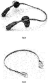
- an external non-implantable BCD is connected to a metallic diadem or an elastic head band that is worn on the head.
- the function of this diadem (see Fig.2a ) or the head band ( Fig.2b ) is to press the BCD against the skin ensuring coupling of the vibrations to the skull bone.
- the main advantage of direct contact of the osseointegrating screw fixture with the skull bone is that one gets rid of the damping of the vibrations through the skin.
- This solution has, however, also an important disadvantage.
- the percutaneous coupling abutment penetrating through the skin causes very frequent infections and inflammatory reactions around the osseointegrating fixture screw and the percutaneous coupling abutment that require medical intervention and sometimes lead even to the loss of the osseointegrating fixture screw.
- BCD bone conduction device
- the invention in a first aspect relates to a device for coupling a bone conduction device, comprising a plate arranged for osseointegration and a coupling abutment for attaching an acoustic BCD to the plate.
- the proposed solution indeed allows for coupling a BCD.
- the device of the invention comprises a plate, preferably a metallic plate, arranged for allowing and stimulating the adhesion and proliferation of osteoinducible cells on its surfaces and the acoustic bone conduction device can be fixed to that plate via the coupling abutment.
- the proposed solution can be used for any person in which general anaesthesia can be applied. This means in practice that even children of only 6 months of age can receive the proposed device. There is no need any more to wait until the bone has reached a certain thickness as is the case in the prior art solutions.
- the device of the invention is made of titanium or tantalum. These materials have the advantageous property of easy osseointegration with the bone.
- the plate can be made of another metal or of another material allowing for osseointegration with living bone.
- the plate comprises a plurality of screw holes, which can be used for primary fixing the plate by means of screws, for example bioresorbable screws, before the osseointegration process ensures the final fixation of the plate to the bone.
- the device for coupling according to this invention comprises at least one cut-out. By providing at least one cut-out additional area is created for bone growth.
- the plate e.g. metallic plate, comprises a transversal connection whereon said coupling is provided.
- the plate is ring shaped. In some embodiments the plate is elliptic.
- a surface of the plate has a lattice or mesh structure arranged for inducing bone formation and osseointegration.
- the surface of the plate that faces the skull of the patient is customized to the 3D anatomy of a patient's skull. That surface may be provided with a lattice or mesh structure.
- the plate comprises at least one position marker. This may facilitate the correct positioning of the plate on the bone surface.
- the part of the coupling abutment closest to the plate is polished.
- a part of said coupling closest to said plate is covered by hydroxyapatite.
- This offers the advantage of an improved healing of the skin and infection prevention.
- another healing coating can be used, for example antibacterial or steroid releasing coatings.
- the plate comprises one or more extensions. These extensions further increase the contact surface with the bone.
- the invention in another aspect relates to a kit of parts comprising a device for coupling as previously described and fixation means for fixating an acoustic bone conduction device to the plate of the device.
- the fixing means comprises metallic screws or bioresorbable screws or bone cement.
- the invention presents a device that facilitates the osseointegrated coupling of a bone conduction device (BCD) to the skull of a patient. It is a major advantage of the proposed device that it can be used even for children as young as 6 months of age, i.e. as soon as a general anaesthesia can be applied. This is in great contrast to the prior art solutions as indicated in the background section.
- BCD bone conduction device
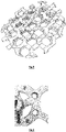
- the device according to the invention comprises an osseointegration-enabled scaffold plate, hereafter sometimes also referred to as 'scaffold plate' or just 'plate', provided with a coupling abutment (further in this description also shortened to 'abutment') for attaching a BCD ( Fig.3a and 3b ).
- a scaffold plate is a 3D matrix, for example a metallic 3D lattice or mesh, that allows and stimulates the adhesion and proliferation of osteoinducible cells on its surfaces.
- the osseointegration-enabled scaffold plate and the abutment can in some embodiments be manufactured as one integrated piece. In alternative embodiments they can be produced as two or more pieces to be connected together with e.g. one or more screws or other fixation means ( Fig.4 .).
- the scaffold plate can have different shapes in different embodiments of the invention, ranging for example from regular circular to oval or irregular, without however being limited thereto.
- the plate, preferably a metallic plate, of the scaffold is ring shaped, for example as a circular or an elliptic ring. Such embodiments were already illustrated in Fig.3 . Such a ring provides the main stability, strength, and fixation to the device.
- the coupling abutment for attachment of a BCD is for example cylindrically or conically shaped.
- the coupling abutment is positioned centrally on the scaffold plate.
- excentric positions are also possible in other embodiments.
- the coupling abutment will pierce the skin once placed, so allowing for fixation of a BCD, for example a commercially available percutaneous BCD. In other embodiments the abutment does not pierce the skin and allows for connecting an implantable BCD with the vibrating part remaining under the skin.
- the coupling abutment is in some embodiments so oriented that, when the device is applied to a patient, the abutment is perpendicular to the skin surface. In that way the abutment is also positioned perpendicular to the underlying bone so that collision is avoided between the BCD and the patient's skull.
- the coupling abutment can in preferred embodiments have different lengths and shapes making it suitable for connecting different percutaneous BCDs with the vibrating element placed above the skin surface as well as implantable BCDs wherein the vibrating part remains under the skin.
- the abutment is advantageously so shaped that the connecting parts of commercially available bone conduction devices fit inside or around the coupling abutment by means of fit geometry or threads.
- the abutment may have a length between for example 1 and 15 millimetres.
- the abutment may be cylindrically or conically shaped.
- a part of the abutment penetrating through the skin may be polished or covered with other biocompatible materials, for example hydroxyapatite or other coatings improving healing of the skin or preventing infection around the coupling abutment, for example antibacterial or steroid releasing coatings.
- the device according to the present invention is preferably made in titanium or tantalum. Titanium and tantalum are preferred materials because of their strength and hardness. Further they are easily osseointegrated with the bone in the form of a direct structural and functional connection between living bone and the surface of a load-bearing artificial implant that ensures increased mechanical stability of the implant. However, also other metals or biocompatible materials can be applied.
- the plate of the device can be primarily attached to the skull of the patient by means of screws, for example metallic or bioresorbable screws.
- the osseointegration-enabled scaffold plate is then provided with a plurality of screw holes, for example two or three or more screw holes.
- the screws hold the device in place during the period of osseointegration.
- the screw holes may be counterbore structures in certain embodiments.
- also other methods for fixation to the patient's skull can be envisaged, for example by means of bone cement.
- the screws can be positioned perpendicular to the bone structure or with an inclination increasing the mechanical stability of the device.
- the scaffold plate gets itself osseointegrated in the bone.
- the scaffold replaces the osseointegrating fixture applied in the prior art solutions as discussed in the background section.
- the scaffold plate can in some embodiments of the device according to the invention be custom made following the three-dimensional (3D) structure of the skull bone. This can be achieved by means of a customised manufacturing, for example based on a computer tomography (CT) scan or a cone-beam computer tomography (CBCT) scan of the patient's skull with subsequent 3D reconstruction of the bone surface.
- CT computer tomography
- CBCT cone-beam computer tomography
- the CT or CBCT images of the patient, including the temporal and parietal region, are collected to obtain a DICOM (Digital Imaging and Communications in Medicine) format image data set.
- DICOM Digital Imaging and Communications in Medicine
- a 3D-model of the patient is acquired from the DICOM format image data.
- the data e.g. the image data, concerning the design of the device may next be transformed into 3D printable and machinable data.
- the post-processing of the appliance may be performed by using a computer numerical control centre or a numerically controlled milling machine, and manually drilling, grinding and polishing. Additional surface treatments can be applied to the device, to optimize for example the osseointegration, the soft tissue integration, sound conduction and healing. This can contain, but is not limited to, an acid etching process, a specialized coating, anodization or any other chemical/mechanical treatment.
- the surface of osseointegration-enabled scaffold plate having contact with the bone can be provided with a lattice or mesh structure capable of inducing bone formation.
- Fig.5 provides an example of such a mesh structure.
- the plate e.g. metallic plate
- the plate comprises, for example on its outer ring, one or more markings that facilitate the correct positioning of the scaffold plate on the bone surface.
- the markers for example arrows, can define e.g. the top-down direction or point at the predefined landmarks ( Fig.6 ).
- the osseointegration-enabled scaffold plate has a form of a disc, e.g. a circular or elliptic disc, with a flat, non-customized undersurface.
- the bone has to be first flattened with a burr in such embodiments.
- the scaffold plate comprises two or more cut-outs with a connecting part in between the cut-outs, as shown in Fig.7 .
- the connecting parts between the cut-outs may form the shape of a cross. Providing these cut-outs is advantageous in that in such a way additional area for bone growth is created, which may reduce the period of time required for the osseointegration.
- Fig.7 an embodiment with a separate coupling abutment is shown. Such abutment is fixed to the osseointegration-enabled scaffold plate by a screw.
- the BCD can fit inside or around the coupling abutment by means of fit geometry or threads.
- the osseointegration-enabled scaffold plate is provided with one or more extensions, as depicted in Fig.8 .
- This increases the surface of the contact with the bone, facilitates osseointegration and ensures increased strength of the coupling to the bone.
- These extensions can be provided with additional screw holes for the primary fixation.
- the different extensions do not necessarily have all the same shape or size. The number and the size of these extensions can be defined on basis of the preoperative CT or CBCT scans in such a way that optimal fixation points relative to the patient's anatomy can be obtained.
- An abutment for coupling a BCD can be attached to the scaffold plate or to the connecting part between the cut-outs.
- this abutment may be integrated with the connecting part of the plate or fixed to it with for example a screw.
- the abutment is centrally positioned on the connecting part.
- excentric positions are also possible in some embodiments.
- the connecting parts in between the cut-outs, lateral relating to the abutment can be recessed or undercut in order to facilitate the removal of the part of the device comprising the coupling abutment in case a problem occurs. In this case there is no need for extensive drill-out of the bone and removal of the whole already osseointegrated scaffold plate.
- the invention in another aspect relates to kit of parts comprising a device for coupling a bone conduction device as described above and fixation means for fixing of the osseointegration-enabled scaffold plate to the bone as well as screw(s) for connecting of the coupling abutment to the osseointegration-enabled scaffold plate.
- a computer program may be stored/distributed on a suitable medium, such as an optical storage medium or a solid-state medium supplied together with or as part of other hardware, but may also be distributed in other forms, such as via the Internet or other wired or wireless telecommunication systems. Any reference signs in the claims should not be construed as limiting the scope.
Landscapes
- Health & Medical Sciences (AREA)
- General Health & Medical Sciences (AREA)
- Otolaryngology (AREA)
- Neurosurgery (AREA)
- Physics & Mathematics (AREA)
- Engineering & Computer Science (AREA)
- Acoustics & Sound (AREA)
- Signal Processing (AREA)
- Surgical Instruments (AREA)
Priority Applications (1)
| Application Number | Priority Date | Filing Date | Title |
|---|---|---|---|
| EP20215247.6A EP4017030A1 (fr) | 2020-12-18 | 2020-12-18 | Dispositif de couplage d'un vibrateur de conduction osseuse |
Applications Claiming Priority (1)
| Application Number | Priority Date | Filing Date | Title |
|---|---|---|---|
| EP20215247.6A EP4017030A1 (fr) | 2020-12-18 | 2020-12-18 | Dispositif de couplage d'un vibrateur de conduction osseuse |
Publications (1)
| Publication Number | Publication Date |
|---|---|
| EP4017030A1 true EP4017030A1 (fr) | 2022-06-22 |
Family
ID=73855644
Family Applications (1)
| Application Number | Title | Priority Date | Filing Date |
|---|---|---|---|
| EP20215247.6A Withdrawn EP4017030A1 (fr) | 2020-12-18 | 2020-12-18 | Dispositif de couplage d'un vibrateur de conduction osseuse |
Country Status (1)
| Country | Link |
|---|---|
| EP (1) | EP4017030A1 (fr) |
Citations (7)
| Publication number | Priority date | Publication date | Assignee | Title |
|---|---|---|---|---|
| JP2001087142A (ja) | 1999-09-20 | 2001-04-03 | Rinnai Corp | ガスグリル |
| US20040032962A1 (en) | 2000-06-02 | 2004-02-19 | Patrik Westerkull | Bone conducting hearing aid |
| US20040234091A1 (en) | 2001-06-21 | 2004-11-25 | Patrick Westerkull | Hearing aid apparatus |
| US20060093175A1 (en) | 2004-11-04 | 2006-05-04 | Patrik Westerkull | Hearing-aid anchoring element |
| US20100112519A1 (en) | 1999-05-31 | 2010-05-06 | Nobel Biocare Ab | Implant, method for producing the implant, and use of the implant |
| WO2015166417A1 (fr) * | 2014-04-29 | 2015-11-05 | Cochlear Limited | Conducteur de vibration percutanée |
| WO2018024275A1 (fr) * | 2016-08-01 | 2018-02-08 | Ralf Siegert | Dispositif de couplage à des appareils d'aide auditive sans inconfort pour les patients |
-
2020
- 2020-12-18 EP EP20215247.6A patent/EP4017030A1/fr not_active Withdrawn
Patent Citations (7)
| Publication number | Priority date | Publication date | Assignee | Title |
|---|---|---|---|---|
| US20100112519A1 (en) | 1999-05-31 | 2010-05-06 | Nobel Biocare Ab | Implant, method for producing the implant, and use of the implant |
| JP2001087142A (ja) | 1999-09-20 | 2001-04-03 | Rinnai Corp | ガスグリル |
| US20040032962A1 (en) | 2000-06-02 | 2004-02-19 | Patrik Westerkull | Bone conducting hearing aid |
| US20040234091A1 (en) | 2001-06-21 | 2004-11-25 | Patrick Westerkull | Hearing aid apparatus |
| US20060093175A1 (en) | 2004-11-04 | 2006-05-04 | Patrik Westerkull | Hearing-aid anchoring element |
| WO2015166417A1 (fr) * | 2014-04-29 | 2015-11-05 | Cochlear Limited | Conducteur de vibration percutanée |
| WO2018024275A1 (fr) * | 2016-08-01 | 2018-02-08 | Ralf Siegert | Dispositif de couplage à des appareils d'aide auditive sans inconfort pour les patients |
Similar Documents
| Publication | Publication Date | Title |
|---|---|---|
| US11439834B2 (en) | Fixation system for an implantable medical device | |
| US20220233869A1 (en) | Implantable device having one or more screws | |
| EP1145734B1 (fr) | Système au moins partiellement implantable de réhabilitation d'un trouble auditif | |
| EP2064916B1 (fr) | Procédés et appareil de traitement des acouphènes | |
| EP1173044B1 (fr) | Système implantable de réhabilitation d'un trouble auditif | |
| EP3550857B1 (fr) | Ensemble de moyens magnétiques pour prothèse auditive à conduction osseuse | |
| US6325755B1 (en) | Mountable transducer assembly with removable sleeve | |
| DE10018360A1 (de) | Mindestens teilimplantierbares System zur Rehabilitation einer Hörstörung | |
| Bruschini et al. | The Carina© middle ear implant: surgical and functional outcomes | |
| EP3412037B1 (fr) | Fixation de transducteur variable | |
| Tsang et al. | The Bonebridge semi-implantable bone conduction hearing device: experience in an Asian patient | |
| CN107106332B (zh) | 用于双侧对称刺激器固定/植入的模板 | |
| US7488284B2 (en) | Implantable prosthesis with direct mechanical stimulation of the inner ear | |
| CN116157180A (zh) | 具有预成形组件的医用植入物 | |
| EP2801390B1 (fr) | Dispositif médical implantable | |
| EP4529868A2 (fr) | Outil de plate-forme de forage pour chirurgies | |
| Koch et al. | Bioengineering solutions for hearing loss and related disorders | |
| CN209075854U (zh) | 一种人工耳蜗 | |
| Tuysuz et al. | Bone-Conducted Implants | |
| JPS6323075Y2 (fr) | ||
| Van der Hulst et al. | First clinical experiences with an implantable bone conduction hearing aid at the University of Amsterdam | |
| CN120826255A (zh) | 用于医疗植入物的粘合剂容置部 | |
| JPS6319060Y2 (fr) | ||
| Kuhn et al. | 32 Implantable Hearing Devices | |
| Traynor et al. | The Future is Here: The Otolodics Fully Inplantable Hearing System |
Legal Events
| Date | Code | Title | Description |
|---|---|---|---|
| PUAI | Public reference made under article 153(3) epc to a published international application that has entered the european phase |
Free format text: ORIGINAL CODE: 0009012 |
|
| STAA | Information on the status of an ep patent application or granted ep patent |
Free format text: STATUS: THE APPLICATION HAS BEEN PUBLISHED |
|
| AK | Designated contracting states |
Kind code of ref document: A1 Designated state(s): AL AT BE BG CH CY CZ DE DK EE ES FI FR GB GR HR HU IE IS IT LI LT LU LV MC MK MT NL NO PL PT RO RS SE SI SK SM TR |
|
| STAA | Information on the status of an ep patent application or granted ep patent |
Free format text: STATUS: THE APPLICATION IS DEEMED TO BE WITHDRAWN |
|
| 18D | Application deemed to be withdrawn |
Effective date: 20221223 |