EP4017172A1 - Procédé et appareil de détermination d'hypothèse de quasi-co-localisation, support de stockage et appareil électronique - Google Patents
Procédé et appareil de détermination d'hypothèse de quasi-co-localisation, support de stockage et appareil électronique Download PDFInfo
- Publication number
- EP4017172A1 EP4017172A1 EP20852538.6A EP20852538A EP4017172A1 EP 4017172 A1 EP4017172 A1 EP 4017172A1 EP 20852538 A EP20852538 A EP 20852538A EP 4017172 A1 EP4017172 A1 EP 4017172A1
- Authority
- EP
- European Patent Office
- Prior art keywords
- reference signal
- source reference
- type
- bwp
- tci state
- Prior art date
- Legal status (The legal status is an assumption and is not a legal conclusion. Google has not performed a legal analysis and makes no representation as to the accuracy of the status listed.)
- Granted
Links
Images



Classifications
-
- H—ELECTRICITY
- H04—ELECTRIC COMMUNICATION TECHNIQUE
- H04L—TRANSMISSION OF DIGITAL INFORMATION, e.g. TELEGRAPHIC COMMUNICATION
- H04L5/00—Arrangements affording multiple use of the transmission path
- H04L5/003—Arrangements for allocating sub-channels of the transmission path
- H04L5/0053—Allocation of signalling, i.e. of overhead other than pilot signals
-
- H—ELECTRICITY
- H04—ELECTRIC COMMUNICATION TECHNIQUE
- H04W—WIRELESS COMMUNICATION NETWORKS
- H04W16/00—Network planning, e.g. coverage or traffic planning tools; Network deployment, e.g. resource partitioning or cells structures
- H04W16/24—Cell structures
- H04W16/28—Cell structures using beam steering
-
- H—ELECTRICITY
- H04—ELECTRIC COMMUNICATION TECHNIQUE
- H04L—TRANSMISSION OF DIGITAL INFORMATION, e.g. TELEGRAPHIC COMMUNICATION
- H04L5/00—Arrangements affording multiple use of the transmission path
- H04L5/003—Arrangements for allocating sub-channels of the transmission path
- H04L5/0032—Distributed allocation, i.e. involving a plurality of allocating devices, each making partial allocation
-
- H—ELECTRICITY
- H04—ELECTRIC COMMUNICATION TECHNIQUE
- H04B—TRANSMISSION
- H04B17/00—Monitoring; Testing
- H04B17/30—Monitoring; Testing of propagation channels
- H04B17/373—Predicting channel quality or other radio frequency [RF] parameters
-
- H—ELECTRICITY
- H04—ELECTRIC COMMUNICATION TECHNIQUE
- H04L—TRANSMISSION OF DIGITAL INFORMATION, e.g. TELEGRAPHIC COMMUNICATION
- H04L5/00—Arrangements affording multiple use of the transmission path
- H04L5/0001—Arrangements for dividing the transmission path
- H04L5/0003—Two-dimensional division
- H04L5/0005—Time-frequency
- H04L5/0007—Time-frequency the frequencies being orthogonal, e.g. OFDM(A) or DMT
- H04L5/001—Time-frequency the frequencies being orthogonal, e.g. OFDM(A) or DMT the frequencies being arranged in component carriers
-
- H—ELECTRICITY
- H04—ELECTRIC COMMUNICATION TECHNIQUE
- H04L—TRANSMISSION OF DIGITAL INFORMATION, e.g. TELEGRAPHIC COMMUNICATION
- H04L5/00—Arrangements affording multiple use of the transmission path
- H04L5/003—Arrangements for allocating sub-channels of the transmission path
- H04L5/0048—Allocation of pilot signals, i.e. of signals known to the receiver
-
- H—ELECTRICITY
- H04—ELECTRIC COMMUNICATION TECHNIQUE
- H04L—TRANSMISSION OF DIGITAL INFORMATION, e.g. TELEGRAPHIC COMMUNICATION
- H04L5/00—Arrangements affording multiple use of the transmission path
- H04L5/003—Arrangements for allocating sub-channels of the transmission path
- H04L5/0048—Allocation of pilot signals, i.e. of signals known to the receiver
- H04L5/005—Allocation of pilot signals, i.e. of signals known to the receiver of common pilots, i.e. pilots destined for multiple users or terminals
-
- H—ELECTRICITY
- H04—ELECTRIC COMMUNICATION TECHNIQUE
- H04L—TRANSMISSION OF DIGITAL INFORMATION, e.g. TELEGRAPHIC COMMUNICATION
- H04L5/00—Arrangements affording multiple use of the transmission path
- H04L5/003—Arrangements for allocating sub-channels of the transmission path
- H04L5/0048—Allocation of pilot signals, i.e. of signals known to the receiver
- H04L5/0051—Allocation of pilot signals, i.e. of signals known to the receiver of dedicated pilots, i.e. pilots destined for a single user or terminal
-
- H—ELECTRICITY
- H04—ELECTRIC COMMUNICATION TECHNIQUE
- H04L—TRANSMISSION OF DIGITAL INFORMATION, e.g. TELEGRAPHIC COMMUNICATION
- H04L5/00—Arrangements affording multiple use of the transmission path
- H04L5/003—Arrangements for allocating sub-channels of the transmission path
- H04L5/0058—Allocation criteria
- H04L5/0064—Rate requirement of the data, e.g. scalable bandwidth, data priority
-
- H—ELECTRICITY
- H04—ELECTRIC COMMUNICATION TECHNIQUE
- H04L—TRANSMISSION OF DIGITAL INFORMATION, e.g. TELEGRAPHIC COMMUNICATION
- H04L5/00—Arrangements affording multiple use of the transmission path
- H04L5/0091—Signalling for the administration of the divided path, e.g. signalling of configuration information
- H04L5/0092—Indication of how the channel is divided
-
- H—ELECTRICITY
- H04—ELECTRIC COMMUNICATION TECHNIQUE
- H04L—TRANSMISSION OF DIGITAL INFORMATION, e.g. TELEGRAPHIC COMMUNICATION
- H04L5/00—Arrangements affording multiple use of the transmission path
- H04L5/0091—Signalling for the administration of the divided path, e.g. signalling of configuration information
- H04L5/0094—Indication of how sub-channels of the path are allocated
-
- H—ELECTRICITY
- H04—ELECTRIC COMMUNICATION TECHNIQUE
- H04W—WIRELESS COMMUNICATION NETWORKS
- H04W72/00—Local resource management
- H04W72/04—Wireless resource allocation
- H04W72/044—Wireless resource allocation based on the type of the allocated resource
- H04W72/0453—Resources in frequency domain, e.g. a carrier in FDMA
-
- H—ELECTRICITY
- H04—ELECTRIC COMMUNICATION TECHNIQUE
- H04W—WIRELESS COMMUNICATION NETWORKS
- H04W72/00—Local resource management
- H04W72/20—Control channels or signalling for resource management
- H04W72/23—Control channels or signalling for resource management in the downlink direction of a wireless link, i.e. towards a terminal
Definitions
- the present disclosure relates to the field of communications, and more particularly to a Quasi-Colocation (QCL) hypothesis determination method and apparatus, a storage medium and an electronic apparatus.
- QCL Quasi-Colocation
- a beam indication method in particular, receiving beam indication of a physical downlink reference signal or channel, such as a Physical Downlink Control Channel (PDCCH), a Physical Downlink Shared Channel (PDSCH) and Channel State Information Reference Signals (CSI-RS) specifically includes the following operations. Firstly, a Transmission Configuration Indication (TCI) state is activated or a TCI state set is selected via a Medium Access Control (MAC)-Control Element (CE) signaling. Then, a QCL hypothesis of a target downlink reference signal or channel is determined according to the TCI state. As an exemplary implementation, a receiving beam of the target downlink reference signal or channel is determined according to a source reference signal configured in QCL-Type D associated with the TCI state. The whole procedure is restricted to a single serving cell or a Component Carrier (CC) or a Bandwidth Part (BWP).
- CC Component Carrier
- BWP Bandwidth Part
- UE User Equipment
- CA Carrier Aggregation
- UE User Equipment
- UE may support a maximum of 16 CCs or BWPs in a downlink connection.
- it is required to activate a TCI state (or select a TCI state set) via a MAC-CE signaling on each CC or BWP to complete beam indications of PDCCHs, PDSCHs and CSI-RSs on all the CCs or BWPs, and thus a maximum of 16 MAC-CE signaling would be required.
- the same beam is indicated for PDCCHs on 16 CCs or BWPs by 16 TCI states activated by 16 MAC-CE signalings, resulting in a large signaling overhead.
- Embodiments of the present disclosure provide a QCL hypothesis determination method and apparatus, a storage medium and an electronic apparatus, which may solve at least the problem of a large signaling overhead caused by activation of a TCI state or a TCI state subset on each CC respectively via a MAC-CE signaling for achieving a beam indication of a PDCCH, a PDSCH or a CSI-RS in the related art.
- a QCL hypothesis determination method determines, according to a TCI state indicated by a first communication node for receiving a target downlink reference signal or channel of a second-type CC or BWP, a QCL hypothesis of the target downlink reference signal or channel of the second-type CC or BWP.
- the indicated TCI state is associated with at least one of following pieces of configuration information: a first source reference signal, a second source reference signal, a set of offsets of a first source reference signal, and a set of CC or BWP indexes corresponding to offsets of a first source reference signal.
- the first source reference signal refers to a source reference signal that is transmitted on a first-type CC or BWP and provides a first QCL type.
- the second source reference signal refers to a source reference signal that is transmitted on the second-type CC or BWP and provides a second QCL type.
- the first-type CC or BWP and the second-type CC or BWP are configured in a same CC group or BWP group.
- a beam indication apparatus is provided.
- a determination module is configured to determine, according to a TCI state indicated by a first communication node for receiving a target downlink reference signal or channel of a second-type CC or BWP, a QCL hypothesis of the target downlink reference signal or channel of the second-type CC or BWP.
- the indicated TCI state is associated with at least one of following pieces of configuration information: a first source reference signal, a second source reference signal, a set of offsets of a first source reference signal, and a set of CC or BWP indexes corresponding to offsets of a first source reference signal.
- the first source reference signal refers to a source reference signal that is transmitted on a first-type CC or BWP and provides a first QCL type.
- the second source reference signal refers to a source reference signal that is transmitted on the first-type CC or BWP and provides a second QCL type.
- the first-type CC or BWP and the second-type CC or BWP are configured in a same CC group or BWP group.
- a second communication node determines, according to a TCI state indicated by a first communication node for receiving a target downlink reference signal or channel of a second-type CC or BWP, a QCL hypothesis of the target downlink reference signal or channel of the second-type CC or BWP.
- the indicated TCI state is associated with at least one of following pieces of configuration information: a first source reference signal, a second source reference signal, a set of offsets of a first source reference signal, and a set of CC or BWP indexes corresponding to offsets of a first source reference signal.
- the first source reference signal refers to a source reference signal that is transmitted on a first-type CC or BWP and provides a first QCL type.
- the second source reference signal refers to a source reference signal that is transmitted on the second-type CC or BWP and provides a second QCL type.
- the first-type CC or BWP and the second-type CC or BWP are configured in a same CC group or BWP group.
- Fig. 1 is a block diagram of a hardware structure of a mobile terminal for implementing a QCL hypothesis determination method according to an embodiment of the present disclosure.
- a mobile terminal 10 may include one or more (only one is shown in Fig. 1 ) processors 102 (the processor 102 may include but is not limited to a processing apparatus such as a Micro Controller Unit (MCU) or a Field Programmable Gate Array (FPGA)) and a memory 104 for storing data.
- MCU Micro Controller Unit
- FPGA Field Programmable Gate Array
- the above mobile terminal may further include a transmission device 106 and an input/output device 108 for communication functions.
- a transmission device 106 may further include a transmission device 106 and an input/output device 108 for communication functions.
- the structure shown in Fig. 1 is merely illustrative, and does not limit the structure of the above mobile terminal.
- the mobile terminal 10 may also include more or fewer components than shown in Fig. 1 , or has a different configuration from that shown in Fig. 1 .
- the memory 104 may be configured to store a computer program, for example, a software program and module of application software, such as a computer program corresponding to a QCL hypothesis determination method in the embodiments of the present disclosure.
- the processor 102 executes various functional applications and data processing, that is, implements the above method by running the computer program stored in the memory 104.
- the memory 104 may include a high speed random access memory and may also include a non-volatile memory such as one or more magnetic storage devices, a flash memory, or other non-volatile solid state memories.
- the memory 104 may further include memories remotely located relative to the processor 102, which may be connected to the mobile terminal 10 over a network.
- the examples of such networks include, but are not limited to, the Internet, the Intranet, local area networks, mobile communication networks, and combinations thereof.
- the transmission device 106 is configured to receive or send data via a network.
- the above specific network examples may include a wireless network provided by a communication provider of the mobile terminal 10.
- the transmission apparatus 106 includes a Network Interface Controller (NIC) that may be connected to other network devices through the base station to communicate with the Internet.
- the transmission device 106 may be a Radio Frequency (RF) module for communicating with the Internet wirelessly.
- NIC Network Interface Controller
- RF Radio Frequency
- FIG. 2 is a flowchart of a QCL hypothesis determination method according to an embodiment of the present disclosure. As shown in Fig. 2 , the flow includes the following operations.
- a second communication node determines, according to a TCI state indicated by a first communication node for receiving a target downlink reference signal or channel of a second-type CC or BWP, a QCL hypothesis of the target downlink reference signal or channel of the second-type CC or BWP.
- the indicated TCI state is associated with at least one of following pieces of configuration information: a first source reference signal, a second source reference signal, a set of offsets of a first source reference signal, and a set of CC or BWP indexes corresponding to offsets of a first source reference signal.
- the first source reference signal refers to a source reference signal that is transmitted on a first-type CC or BWP and provides a first QCL type.
- the second source reference signal refers to a source reference signal that is transmitted on the first-type CC or BWP and provides a second QCL type.
- the first-type CC or BWP and the second-type CC or BWP are configured in a same CC group or BWP group.
- the method of the present disclosure may further include the following operations.
- the second communication node determines a third source reference signal according to a preset rule and the configuration information associated with the indicated TCI state.
- the preset rule includes at least one of a first preset rule, a second preset rule and a third preset rule.
- the third source reference signal refers to a source reference signal that is transmitted on the second-type CC or BWP and provides the first QCL type for the target downlink reference signal or channel.
- the method of the present disclosure may further include the following operations.
- the second communication node determines the third source reference signal according to the first preset rule and the first source reference signal associated with the indicated TCI state.
- the first preset rule includes at least one of the following: the first source reference signal is configured as a reference signal of the third source reference signal; the first source reference signal is configured as a reference signal of a first reference signal associated with the third source reference signal; the first source reference signal is configured in a second QCL type of a TCI state applied to the third source reference signal; the first source reference signal is configured in a second QCL type of a TCI state applied to a first reference signal associated with the third source reference signal; a second reference signal associated with the first source reference signal is configured in a second QCL type of a TCI state applied to the third source reference signal; the fourth source reference signal is configured in a second QCL type of a TCI state applied to the third source reference signal; and the fourth source reference signal is configured in a second QCL type of a TCI state applied to a first reference signal associated with the third source reference signal.
- the first reference signal includes a periodic CSI-RS transmitted on the second-type CC or BWP.
- the second reference signal includes a periodic CSI-RS transmitted on the first-type CC or BWP.
- the fourth source reference signal is configured in a second QCL type of a TCI state applied to the first source reference signal.
- the method of the present disclosure may further include the following operations.
- the second communication node determines the third source reference signal according to the second preset rule and the second source reference signal associated with the indicated TCI state.
- the second preset rule includes at least one of the following: the second source reference signal is configured in a second QCL type of a TCI state applied to the third source reference signal; and the second source reference signal is configured in a second QCL type of a TCI state applied to a first reference signal associated with the third source reference signal.
- the first reference signal includes a periodic CSI-RS transmitted on the second-type CC or BWP.
- the second source reference signal is configured in a first QCL type and a second QCL type of a TCI state applied to the third source reference signal.
- the method of the present disclosure may further include the following operations.
- the second communication node determines the third source reference signal according to the third preset rule and the first source reference signal or the second source reference signal associated with the indicated TCI state.
- the third preset rule includes at least one of the following: the first source reference signal or the second source reference signal is configured in a first QCL type of a TCI state applied to the third source reference signal; the first source reference signal or the second source reference signal is configured in a second QCL type of a TCI state applied to the third source reference signal; and the first source reference signal or the second source reference signal is configured in a first QCL type and a second QCL type of a TCI state applied to the third source reference signal.
- the first source reference signal or the second source reference signal includes an SSB transmitted on the first-type CC.
- the method of the present disclosure may further include the following operations.
- the second communication node determines the third source reference signal according to the first source reference signal associated with the indicated TCI state, the set of offsets of the first source reference signal, and the set of CC or BWP indexes corresponding to the offsets of the first source reference signal.
- the method of the present disclosure may further include the following operations.
- the second communication node determines a fifth source reference signal according to a reference signal configured in a second QCL type of a TCI state of a Control Resource Set (CORESET), that is used for scheduling a target downlink reference signal or channel of the second-type CC or BWP, on the first-type CC or BWP.
- CORESET Control Resource Set
- the fifth source reference signal refers to a source reference signal that is transmitted on the first-type CC or BWP or the second-type CC or BWP and provides a second QCL type for the target downlink reference signal or channel.
- the method of the present disclosure may further include the following operations.
- the second communication node determines a fifth source reference signal according to a reference signal configured in a second QCL type of a TCI state of a CORESET having a minimum CORESET ID on the first-type CC.
- the method of the present disclosure may further include the following operations.
- the second communication node determines, according to a candidate TCI state indicated by the first communication node for receiving the target downlink reference signal or channel of the second-type CC or BWP, a QCL hypothesis of the target downlink reference signal or channel of the second-type CC or BWP.
- the candidate TCI state is associated with at least one of following pieces of configuration information: a first source reference signal, a second source reference signal, a set of offsets of a first source reference signal, and a set of CC or BWP indexes corresponding to offsets of a first source reference signal.
- the first preset condition in the present disclosure includes: a time interval between a target downlink reference signal or channel on the second-type CC or BWP and a CORESET for scheduling the target downlink reference signal or channel is smaller than a preset threshold.
- the method of the present disclosure may further include the following operations.
- the second communication node determines the first source reference signal and a third source reference signal according to a fourth preset rule.
- the third source reference signal refers to a source reference signal that is transmitted on the second-type CC or BWP and provides the first QCL type for the target downlink reference signal or channel.
- the fourth preset rule includes: the first source reference signal is a CSI-RS that is transmitted on the first-type CC or BWP, has a minimum CSI-RS resource ID and is configured with TRS-Info; and the third source reference signal is a CSI-RS that is transmitted on the second-type CC or BWP, has a minimum CSI-RS resource ID and is configured with TRS-Info.
- the method of the present disclosure may further include the following operations. Before the second communication node receives the TCI state indicated by the first communication node for receiving the target downlink reference signal or channel of the second-type CC or BWP, the second communication node determines the indicated TCI state according to a first TCI state in a TCI state set configured by the first communication node for a reference CC or BWP.
- the first TCI state is associated with at least one of following pieces of configuration information: a first source reference signal, a second source reference signal, a set of offsets of a first source reference signal, and a set of CC or BWP indexes corresponding to offsets of a first source reference signal.
- the reference CC or BWP, the first-type CC or BWP and the second-type CC or BWP are configured in a same CC group or BWP group.
- the second communication node is capable of obtaining the first TCI state according to at least one of following manners: the first TCI state is the 1st TCI state in the TCI state set; and the first communication node activates the first TCI state from the TCI state set via an activation command.
- the reference CC or BWP includes at least one of: a CC or BWP having a minimum CC or BWP index in the CC group or BWP group; a CC or BWP having a minimum interval from an index of the second-type CC or BWP in the CC group or BWP group; and a CC or BWP that is closest to a frequency domain position of the second-type CC or BWP in the CC group or BWP group.
- the technical solution of the present disclosure which is essential or contributes to the conventional art, may be embodied in the form of a software product stored in a storage medium (such as a Read-Only Memory (ROM)/Random Access Memory (RAM), a magnetic disk and an optical disc), including a number of instructions for causing a terminal device (which may be a mobile phone, a computer, a server, or a network device, etc.) to perform the methods described in various embodiments of the present disclosure.
- a storage medium such as a Read-Only Memory (ROM)/Random Access Memory (RAM), a magnetic disk and an optical disc
- a terminal device which may be a mobile phone, a computer, a server, or a network device, etc.
- a QCL hypothesis determination apparatus is also provided.
- the apparatus is used to implement the above embodiments and exemplary implementations, and those have not been described will not be elaborated.
- the term "module” may implement a combination of software and/or hardware of a predetermined function.
- the apparatus described in the following embodiments is preferably implemented by software, hardware or a combination of software and hardware is also possible and conceived.
- Fig. 3 is a structural schematic diagram of a QCL hypothesis determination apparatus according to the present disclosure.
- the apparatus is applied to a second communication node side.
- the apparatus includes: a determination module 32.
- the determination module 32 is configured to determine, according to a TCI state indicated by a first communication node for receiving a target downlink reference signal or channel of a second-type CC or BWP, a QCL hypothesis of the target downlink reference signal or channel of the second-type CC or BWP.
- the indicated TCI state is associated with at least one of following pieces of configuration information: a first source reference signal, a second source reference signal, a set of offsets of a first source reference signal, and a set of CC or BWP indexes corresponding to offsets of a first source reference signal.
- the first source reference signal refers to a source reference signal that is transmitted on a first-type CC or BWP and provides a first QCL type.
- the second source reference signal refers to a source reference signal that is transmitted on the first-type CC or BWP and provides a second QCL type.
- the first-type CC or BWP and the second-type CC or BWP are configured in a same CC group or BWP group.
- each of the above modules may be implemented by software or hardware.
- it may be implemented by, but not limited to, the following manners that the above modules are all located in the same processor; or, the above modules are located in different processors in any combination form respectively.
- a CC or BWP group configuration method is provided.
- the configuration mode of a CC or BWP group may include at least one of the following:
- the number of CCs or BWPs included in one CC or BWP group is smaller than or equal to N max , where N max refers to a maximum number of CCs or BWPs supportable by the UE.
- CC referred to in the following embodiments represents a CC or BWP
- CC group represents a CC or BWP group
- exemplary embodiments 2 to 5 relate to a QCL hypothesis determination method for, but not limited to, a PDSCH.
- the method is also applicable to a PDCCH, and the determination of QCL hypothesis of a CSI-RS used for obtaining CSI.
- the present example provides a QCL hypothesis determination method for a PDSCH of a CC group. It is assumed that a CC group includes CC1 and CC2. SSB1 and CSI-RS1 are transmitted on CC1, and CSI-RS2 is transmitted on CC2. A base station indicates one TCI state for receiving a target PDSCH of the CC group.
- the TCI state is associated with the following configuration information: a first source reference signal and a second source reference signal.
- the first source reference signal refers to a source reference signal that is transmitted on a first-type CC and provides a first QCL type
- the second source reference signal refers to a source reference signal that is transmitted on the first-type CC and provides a second QCL type.
- the first source reference signal and the second source reference signal are respectively SSB1 and CSI-RS1.
- the first-type CC may be a CC with a minimum CC index in the CC group or a primary serving cell (PCell), i.e. CC1.
- the first QCL type refers to QCL-Type A, indicating that the target reference signal and the source reference signal have the same demodulation parameters (such as Doppler frequency shift, Doppler spread, average delay, and delay spread).
- the second QCL type refers to QCL-Type D, indicating that the target reference signal and the source reference signal have the same receiving space parameter, i.e. having the same receiving beam.
- SSB1 is configured in QCL-Type D applied to CSI-RS1, i.e.
- SSB1 and CSI-RS1 have the same receiving beam.
- SSB1 provides QCL-Type D for a target PDSCH of the first-type CC and the second-type CC (i.e. a source reference signal of QCL-Type D of the target PDSCH of the second-type CC is determined according to a second source reference signal, and is also SSB1, which is applicable to Embodiments 2 to 5).
- the second-type CC may be a CC other than the first-type CC in the CC group, such as CC2, i.e. the PDSCH of the first-type CC and the PDSCH of the second-type CC have the same receiving beam as SSB1.
- CSI-RS1 provides QCL-Type A for the target PDSCH of the first-type CC, i.e. the target PDSCH of the first-type CC has the same demodulation parameter as CSI-RS1.
- the UE may determine a third source reference signal according to a first preset rule and the first source reference signal (SSB1) associated with the indicated TCI state.
- the third source reference signal is transmitted on CC2 (assumed to be CSI-RS2), and provides QCL-Type A for the target PDSCH of the second-type CC, i.e. the target PDSCH of the second-type CC and CSI-RS2 have the same demodulation parameter.
- the first preset rule may include at least one of the following:
- the UE may determine the third source reference signal according to the fourth source reference signal (SSB1) associated with the indicated TCI state and the following (first) preset rule: 4)
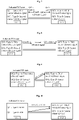
- the fourth source reference signal (SSB1) is configured in QCL-Type D applied to the third source reference signal (CSI-RS2), as shown in Fig. 7 .
- the UE may determine the third source reference signal according to the first source reference signal (SSB1) associated with the indicated TCI state and the following (first) preset rule:
- the UE may determine the third source reference signal according to the first source reference signal (CSI-RS5) associated with the indicated TCI state and the following (first) preset rule:
- the UE may also determine the third source reference signal according to the second source reference signal (CSI-RS1) associated with the indicated TCI state and a second preset rule.
- CSI-RS1 second source reference signal
- the second preset rule may include at least one of the following:
- the UE may determine the third source reference signal according to the second source reference signal (CSI-RS1) associated with the indicated TCI state and the following (second) preset rule: 2) Similar to criterion 1), the second source reference signal (CSI-RS1) is configured in QCL-Type D of a TCI state applied to the third reference signal (CSI-RS7) associated with the third source reference signal (CSI-RS2).
- the present example provides a QCL hypothesis determination method for a PDSCH of a CC group. It is assumed that a CC group includes CC1 and CC2. SSB1 is transmitted on CC1, and CSI-RS1 is transmitted on CC2. A base station indicates one TCI state for receiving a target PDSCH of the CC group.
- the TCI state is associated with the following configuration information: a first source reference signal and a second source reference signal.
- the first source reference signal refers to a source reference signal that is transmitted on a first-type CC and provides a first QCL type
- the second source reference signal refers to a source reference signal that is transmitted on the first-type CC and provides a second QCL type.
- the first-type CC may be a CC with a minimum CC index in the CC group or a primary serving cell (PCell), i.e. CC1.
- the first QCL type refers to QCL-Type C.
- the second QCL type refers to QCL-Type D.
- SSB1 provides QCL-Type D for a target PDSCH of the first-type CC and the second-type CC.
- the second-type CC may be a CC other than the first-type CC in the CC group, i.e.
- the PDSCH of the first-type CC and the PDSCH of the second-type CC have the same receiving beam as SSB1.
- SSB1 provides QCL-Type C for the target PDSCH of the first-type CC, i.e. the target PDSCH of the first-type CC has the same synchronization parameter as SSB1.
- the UE may determine a third source reference signal according to the first source reference signal or second source reference signal (SSB1) associated with the indicated TCI state and a third preset rule.
- the third source reference signal is transmitted on CC2 (assumed to be CSI-RS1), and provides QCL-Type C for the target PDSCH of the second-type CC, i.e. the target PDSCH of the second-type CC and CSI-RS1 have the same synchronization parameter.
- the third preset rule may include at least one of the following:
- first source reference signal and the second source reference signal can only include SSBs.
- the present example provides a QCL hypothesis determination method for a PDSCH of a CC group. It is assumed that a CC group includes CC1 and CC2. CSI-RS1 and CSI-RS2 are transmitted on CC1, and CSI-RS3 is transmitted on CC2. CSI-RS1 and CSI-RS3 are from the same CSI-RS set. A base station indicates one TCI state for receiving a target PDSCH of the CC group.
- the TCI state is associated with the following configuration information: a first source reference signal (CSI-RS1), a second source reference signal (CSI-RS2), a set of offsets ⁇ 2 ⁇ of the first source reference signal, and a set of CC indexes ⁇ 2 ⁇ corresponding to the offsets of the first source reference signal.
- the first source reference signal refers to a source reference signal that is transmitted on a first-type CC and provides a first QCL type
- the second source reference signal refers to a source reference signal that is transmitted on the first-type CC and provides a second QCL type.
- the first-type CC may be a CC with a minimum CC index in the CC group or a primary serving cell (PCell), i.e. CC1.
- the first QCL type refers to QCL-Type A or QCL-Type C (it is assumed here that the first QCL type refers to QCL-Type A), and the second QCL type refers to QCL-Type D.
- the CCs included in a set of CC indexes corresponding to the offsets of the first source reference signal belong to a second-type CC.
- the first source reference signal indicates a difference value between third source reference signal indexes of these CCs and first source reference signal indexes, and elements included in the set of offsets of the first source reference signal are in one-to-one correspondence with elements included in the set of CCs indexes corresponding to the offsets of the first source reference signal.
- the third source reference signal is transmitted on the second-type CC, and provides a source reference signal of a first QCL type for a target PDSCH of the second-type CC. Further, the third source reference signal belongs to the same set of reference signals as the first source reference signal.
- CSI-RS2 After a UE receives the above indicated TCI state, CSI-RS2 provides QCL-Type D for a target PDSCH of the first-type CC and the second-type CC, i.e. the PDSCH of the first-type CC and the PDSCH of the second-type CC have the same receiving beam as CSI-RS2.
- the second-type CC may be a CC other than the first-type CC in the CC group.
- CSI-RS1 provides QCL-Type A for the target PDSCH of the first-type CC, i.e. the target PDSCH of the first-type CC has the same demodulation parameter as CSI-RS1.
- the UE may determine a third source reference signal according to the first source reference signal, the set of offsets of the first source reference signal and the set of CC indexes corresponding to the offsets of the first source reference signal, which are associated with the indicated TCI state.
- the third source reference signal is CSI-RS1+2 transmitted on CC2, i.e. CSI-RS3.
- the present example provides a QCL hypothesis determination method for a PDSCH of a CC group. It is assumed that a CC group includes CC1 and CC2. CSI-RS1, CSI-RS2, CSI-RS3, CSI-RS4 and CSI-RS5 are transmitted on CC1, and CSI-RS6, CSI-RS7, CSI-RS8, CSI-RS9 and CSI-RS10 are transmitted on CC2. CSI-RS1, CSI-RS2, CSI-RS3, CSI-RS6, CSI-RS7 and CSI-RS8 are configured with TRS-Info.
- a base station indicates one TCI state for receiving a target PDSCH of the CC group.
- the TCI state is associated with the following configuration information: a first source reference signal and a second source reference signal (CSI-RS3).
- the first source reference signal refers to a source reference signal that is transmitted on a first-type CC and provides a first QCL type (e.g. QCL-Type A)
- the second source reference signal refers to a source reference signal that is transmitted on the first-type CC and provides a second QCL type (e.g. QCL-Type D).
- the first-type CC may be a CC with a minimum CC index in the CC group or a primary serving cell (PCell), i.e. CC1.
- CSI-RS2 After a UE receives the above indicated TCI state, CSI-RS2 provides QCL-Type D for a target PDSCH of the first-type CC and the second-type CC, i.e. the PDSCH of the first-type CC and the PDSCH of the second-type CC have the same receiving beam as CSI-RS2.
- the second-type CC may be a CC other than the first-type CC in the CC group.
- the UE For QCL-Type A of the target PDSCH of the first-type CC and the second-type CC, the UE may determine the first source reference signal and a third source reference signal according to a fourth preset rule.
- the third source reference signal provides QCL-Type C for the target PDSCH of the second-type CC, i.e. the target PDSCH of the second-type CC and the third source reference signal have the same synchronization parameter.
- the fourth preset rule includes:
- the UE may determine that the first source reference signal is CSI-RS 1 and the third source reference signal is CSI-RS5 according to the fourth preset rule.
- the present example provides a TCI state obtaining method.
- the exemplary implementation may be applied to the cases of exemplary implementations 2 to 5, but is not limited to the cases involved in these embodiments.
- a UE Before a base station indicates a TCI state for receiving a target PDSCH of a second-type CC, a UE may obtain the indicated TCI state according to a first TCI state in a TCI state set configured by the base station for a reference CC.
- the reference CC belongs to the same CC group as the first-type CC and the second-type CC involved in Embodiments 2 to 5.
- the first TCI state is associated with at least one of following pieces of configuration information: a first source reference signal, a second source reference signal, a set of offsets of a first source reference signal, and a set of CC or BWP indexes corresponding to offsets of a first source reference signal.
- the UE may obtain the first TCI state according to at least one of following manners:
- reference CC may include at least one of:
- the present example provides a QCL hypothesis determination method for a PDSCH. It is assumed that a CC group includes CC1 and CC2. A UE is configured with three CORESETs: CORESET0, CORESET1 and CORESET2. These CORESETs are on CC1, and DCI located on CORESET2 is used for scheduling PDSCH1 on CC1 and PDSCH2 on CC2. TCI states respectively indicated by a base station for receiving CORESET0, CORESET1 and CORESET2 are TCI state 1, TCI state 2 and TCI state 3.
- TCI state 1 is associated with the following configuration information: a fifth source reference signal (assumed to be CSI-RS1) and a sixth source reference signal (assumed to be CSI-RS4).
- TCI state 2 is associated with the following configuration information: a fifth source reference signal (assumed to be CSI-RS2) and a sixth source reference signal (assumed to be CSI-RS5).
- TCI state 3 is associated with the following configuration information: a fifth source reference signal (assumed to be CSI-RS3) and a sixth source reference signal (assumed to be CSI-RS6).
- the fifth source reference signal refers to a source reference signal that is transmitted on a first-type CC and provides a first QCL type (e.g. QCL-Type A), and the sixth source reference signal refers to a source reference signal that is transmitted on the first-type CC and provides a second QCL type (e.g. QCL-Type D).
- the first-type CC may be a CC with a minimum CC index in a CC group or a primary serving cell (PCell), i.e. CC1.
- the UE may determine a seventh source reference signal according to the sixth source reference signal (CSI-RS6) associated with TCI state 3 of CORESET2 for scheduling a PDSCH on CC2 on the first-type CC, as shown in Fig. 11 , i.e. PDSCH2 and CSI-RS6 have the same receiving beam.
- the seventh source reference signal refers to a source reference signal providing QCL-Type D for target PDSCH2 of a second-type CC.
- the second-type CC may be a CC (e.g. CC2) other than the first-type CC in the CC group.
- the UE may determine the seventh source reference signal according to the sixth source reference signal (CSI-RS4) associated with TCI state 1 of CORESET0 with a minimum CORESET ID on the first-type CC, i.e. PDSCH2 and CSI-RS4 have the same receiving beam.
- the closest distance refers to the closest distance to the target PDSCH in a time domain.
- the first preset condition includes: a time interval (or scheduling offset) T between a target PDSCH of the second-type CC and a CORESET for scheduling the target PDSCH is smaller than a preset threshold K.
- the present example provides a QCL hypothesis determination method for a PDSCH of a CC group. It is assumed that a CC group includes CC1 and CC2.
- a base station indicates one TCI state for receiving a target PDSCH of the CC group (referred to herein as a primary TCI state temporarily), and also indicates one candidate TCI state. Both the primary TCI state and the candidate TCI state are associated with at least one of the following configuration information: a first source reference signal, a second source reference signal, a set of offsets of a first source reference signal, and a set of CC indexes corresponding to the offsets of the first source reference signal.
- a UE may determine the third source reference signal involved in Embodiments 2-5 according to the configuration information associated with the indicated candidate TCI state and the first, second, third and fourth criteria involved in Embodiments 2-5.
- the first preset condition includes: a time interval (or scheduling offset) T between a target PDSCH of the second-type CC and a CORESET for scheduling the target PDSCH is smaller than a preset threshold K.
- An embodiment of the present disclosure also provides a storage medium.
- the storage medium has a computer program stored therein, wherein the computer program, when run, is configured to perform the operations in any one of the above method embodiments.
- the storage medium may be configured to store a computer program for performing the following operations.
- a QCL hypothesis of the target downlink reference signal or channel of the second-type CC or BWP is determined.
- the storage medium may include, but is not limited to, various media capable of storing a computer program such as a U disk, a ROM, a RAM, a mobile hard disk, a magnetic disk or an optical disc.
- An embodiment of the present disclosure also provides an electronic apparatus, which includes a memory and a processor.
- the memory stores a computer program.
- the processor is configured to run the computer program to perform the operations in any one of the above method embodiments.
- the electronic apparatus may further include a transmission device and an input/output device, where the transmission device is connected to the processor, and the input/output device is connected to the processor.
- the processor may be configured to perform the following operations through the computer program.
- a QCL hypothesis of the target downlink reference signal or channel of the second-type CC or BWP is determined.
- the present disclosure is not limited to any particular combination of hardware and software.
Landscapes
- Engineering & Computer Science (AREA)
- Signal Processing (AREA)
- Computer Networks & Wireless Communication (AREA)
- Quality & Reliability (AREA)
- Physics & Mathematics (AREA)
- Electromagnetism (AREA)
- Mobile Radio Communication Systems (AREA)
- Radar Systems Or Details Thereof (AREA)
Priority Applications (1)
| Application Number | Priority Date | Filing Date | Title |
|---|---|---|---|
| EP25187158.8A EP4604640A3 (fr) | 2019-08-15 | 2020-08-12 | Procédé et appareil de détermination d'hypothèse de quasi-colocalisation, support de stockage et appareil électronique |
Applications Claiming Priority (2)
| Application Number | Priority Date | Filing Date | Title |
|---|---|---|---|
| CN201910755329.1A CN111082909B (zh) | 2019-08-15 | 2019-08-15 | 准共址假设的确定方法及装置、存储介质和电子装置 |
| PCT/CN2020/108705 WO2021027849A1 (fr) | 2019-08-15 | 2020-08-12 | Procédé et appareil de détermination d'hypothèse de quasi-co-localisation, support de stockage et appareil électronique |
Related Child Applications (2)
| Application Number | Title | Priority Date | Filing Date |
|---|---|---|---|
| EP25187158.8A Division EP4604640A3 (fr) | 2019-08-15 | 2020-08-12 | Procédé et appareil de détermination d'hypothèse de quasi-colocalisation, support de stockage et appareil électronique |
| EP25187158.8A Division-Into EP4604640A3 (fr) | 2019-08-15 | 2020-08-12 | Procédé et appareil de détermination d'hypothèse de quasi-colocalisation, support de stockage et appareil électronique |
Publications (3)
| Publication Number | Publication Date |
|---|---|
| EP4017172A1 true EP4017172A1 (fr) | 2022-06-22 |
| EP4017172A4 EP4017172A4 (fr) | 2022-08-31 |
| EP4017172B1 EP4017172B1 (fr) | 2025-10-01 |
Family
ID=70310167
Family Applications (2)
| Application Number | Title | Priority Date | Filing Date |
|---|---|---|---|
| EP25187158.8A Pending EP4604640A3 (fr) | 2019-08-15 | 2020-08-12 | Procédé et appareil de détermination d'hypothèse de quasi-colocalisation, support de stockage et appareil électronique |
| EP20852538.6A Active EP4017172B1 (fr) | 2019-08-15 | 2020-08-12 | Procédé et appareil de détermination d'hypothèse de quasi-co-localisation, support de stockage et appareil électronique |
Family Applications Before (1)
| Application Number | Title | Priority Date | Filing Date |
|---|---|---|---|
| EP25187158.8A Pending EP4604640A3 (fr) | 2019-08-15 | 2020-08-12 | Procédé et appareil de détermination d'hypothèse de quasi-colocalisation, support de stockage et appareil électronique |
Country Status (6)
| Country | Link |
|---|---|
| US (1) | US12127010B2 (fr) |
| EP (2) | EP4604640A3 (fr) |
| JP (1) | JP7704736B2 (fr) |
| KR (1) | KR20220047314A (fr) |
| CN (1) | CN111082909B (fr) |
| WO (1) | WO2021027849A1 (fr) |
Families Citing this family (16)
| Publication number | Priority date | Publication date | Assignee | Title |
|---|---|---|---|---|
| CN111082909B (zh) * | 2019-08-15 | 2024-06-07 | 中兴通讯股份有限公司 | 准共址假设的确定方法及装置、存储介质和电子装置 |
| CN115462119A (zh) * | 2020-04-30 | 2022-12-09 | 株式会社Ntt都科摩 | 终端、无线通信方法以及基站 |
| US11937098B2 (en) | 2020-05-14 | 2024-03-19 | Apple Inc. | Spatial relation and pathloss reference signal for multi-TRP operation |
| CN113811002B (zh) | 2020-06-16 | 2025-01-28 | 中国移动通信有限公司研究院 | 信息传输方法、装置、相关设备及存储设备 |
| CN113949421B (zh) * | 2020-07-17 | 2023-02-24 | 维沃移动通信有限公司 | 确定波束信息的方法、装置及电子设备 |
| CN114205015B (zh) * | 2020-09-18 | 2023-06-06 | 维沃移动通信有限公司 | 测量方法、发送方法及相关设备 |
| WO2022082462A1 (fr) * | 2020-10-20 | 2022-04-28 | 华为技术有限公司 | Procédé et appareil de communication |
| CN114745784B (zh) * | 2021-01-07 | 2025-04-29 | 北京紫光展锐通信技术有限公司 | 一种信息确定方法及通信装置 |
| US12074818B2 (en) | 2021-01-13 | 2024-08-27 | Apple Inc. | TCI chain design |
| CN115118405B (zh) * | 2021-03-23 | 2023-06-27 | 大唐移动通信设备有限公司 | 一种信息处理方法、装置及可读存储介质 |
| CN115175106B (zh) * | 2021-04-01 | 2024-09-27 | 北京紫光展锐通信技术有限公司 | 通信参数确定方法及相关产品 |
| CN115714636B (zh) * | 2021-08-23 | 2024-11-22 | 上海推络通信科技合伙企业(有限合伙) | 一种被用于无线通信的节点中的方法和装置 |
| WO2023050257A1 (fr) * | 2021-09-30 | 2023-04-06 | Qualcomm Incorporated | Application d'un état d'indicateur de configuration de transmission (tci) unifié à un signal de référence de liaison descendante |
| CN117595902A (zh) * | 2021-10-23 | 2024-02-23 | 上海朗帛通信技术有限公司 | 一种被用于无线通信的节点中的方法和装置 |
| CN116264698A (zh) * | 2021-12-13 | 2023-06-16 | 上海朗帛通信技术有限公司 | 一种被用于无线通信的节点中的方法和装置 |
| EP4461056A4 (fr) * | 2022-01-06 | 2025-11-05 | Qualcomm Inc | Configuration d'états candidats d'indicateur de configuration de transmission |
Family Cites Families (13)
| Publication number | Priority date | Publication date | Assignee | Title |
|---|---|---|---|---|
| WO2014112841A1 (fr) * | 2013-01-18 | 2014-07-24 | 엘지전자 주식회사 | Procédé et appareil pour effectuer une quasi-colocalisation dans un système d'accès sans fil |
| CN105122869B (zh) | 2013-04-08 | 2019-06-14 | Lg电子株式会社 | 在无线通信系统中针对部分波束成形报告信道状态信息的方法和设备 |
| US9888469B2 (en) | 2014-03-19 | 2018-02-06 | Nec Corporation | Signalling for coordinated multi-point transmission and reception (CoMP) |
| US9906344B2 (en) | 2015-02-23 | 2018-02-27 | Intel Corporation | Methods, apparatuses, and systems for multi-point, multi-cell single-user based multiple input and multiple output transmissions |
| CN108633029B (zh) | 2017-03-24 | 2023-05-02 | 中兴通讯股份有限公司 | 波束指示方法及装置 |
| CN114666904B (zh) | 2017-08-11 | 2026-02-13 | 华为技术有限公司 | 通信方法及装置 |
| US11743879B2 (en) | 2017-11-03 | 2023-08-29 | Futurewei Technologies, Inc. | System and method for indicating wireless channel status |
| US10764896B2 (en) * | 2017-11-08 | 2020-09-01 | Samsung Electronics Co., Ltd. | Method and apparatus for beam management in the unlicensed spectrum |
| EP4243325B1 (fr) * | 2017-11-15 | 2026-02-18 | InterDigital Patent Holdings, Inc. | Gestion de faisceau dans un réseau sans fil |
| CN108092754B (zh) * | 2017-11-17 | 2021-10-26 | 中兴通讯股份有限公司 | 一种参考信号信道特征配置方法和装置、及通信设备 |
| JP2019118036A (ja) | 2017-12-27 | 2019-07-18 | シャープ株式会社 | 基地局装置、端末装置および通信方法 |
| ES2894734T3 (es) * | 2018-01-12 | 2022-02-15 | Guangdong Oppo Mobile Telecommunications Corp Ltd | Método de configuración de transmisión y producto relacionado |
| CN111082909B (zh) | 2019-08-15 | 2024-06-07 | 中兴通讯股份有限公司 | 准共址假设的确定方法及装置、存储介质和电子装置 |
-
2019
- 2019-08-15 CN CN201910755329.1A patent/CN111082909B/zh active Active
-
2020
- 2020-08-12 WO PCT/CN2020/108705 patent/WO2021027849A1/fr not_active Ceased
- 2020-08-12 EP EP25187158.8A patent/EP4604640A3/fr active Pending
- 2020-08-12 EP EP20852538.6A patent/EP4017172B1/fr active Active
- 2020-08-12 KR KR1020227007979A patent/KR20220047314A/ko active Pending
- 2020-08-12 JP JP2022509603A patent/JP7704736B2/ja active Active
- 2020-08-12 US US17/635,447 patent/US12127010B2/en active Active
Also Published As
| Publication number | Publication date |
|---|---|
| US20220338021A1 (en) | 2022-10-20 |
| US12127010B2 (en) | 2024-10-22 |
| KR20220047314A (ko) | 2022-04-15 |
| EP4604640A2 (fr) | 2025-08-20 |
| EP4604640A3 (fr) | 2025-11-19 |
| EP4017172B1 (fr) | 2025-10-01 |
| JP2022544419A (ja) | 2022-10-18 |
| CN111082909A (zh) | 2020-04-28 |
| WO2021027849A1 (fr) | 2021-02-18 |
| JP7704736B2 (ja) | 2025-07-08 |
| CN111082909B (zh) | 2024-06-07 |
| EP4017172A4 (fr) | 2022-08-31 |
Similar Documents
| Publication | Publication Date | Title |
|---|---|---|
| US12127010B2 (en) | Quasi co-location hypothesis determination method and apparatus, storage medium and electronic apparatus | |
| EP4044489B1 (fr) | Procédé et dispositif de détermination d'informations, dispositif électronique et support d'informations | |
| US12010059B2 (en) | Methods and apparatuses for reference signal configuration | |
| US11700094B2 (en) | Signal transmission method and apparatus | |
| KR102758224B1 (ko) | 통신 방법 및 통신 장치 | |
| CN110972288B (zh) | 传输信号的方法和通信装置 | |
| US11218263B2 (en) | Method for determining reference signal, network device, UE, and computer storage medium | |
| CN111901838B (zh) | 一种信令接收、发送方法及设备 | |
| JP2021522753A (ja) | チャネル構成方法および装置、電力制御方法および装置、ユーザ機器、基地局、および記憶媒体 | |
| JP7662660B2 (ja) | 空間パラメータの決定方法及び装置 | |
| US20240243889A1 (en) | Method for signal communication, communication node, and storage medium | |
| US20240284279A1 (en) | Method, user equipment, and base station for managing l1/l2 triggered mobility | |
| EP3817269A1 (fr) | Procédé et dispositif de gestion de ressources | |
| CN111479326A (zh) | 一种信息发送、检测方法及装置 | |
| US20250323775A1 (en) | Mechanism for handling predictive beam configurations | |
| RU2819698C2 (ru) | Способ и устройство определения гипотезы квазиколокации, носитель информации и электронное устройство | |
| CN115706646A (zh) | 波束指示方法、装置、终端及基站 | |
| US20250274780A1 (en) | Mechanism for generating predictive beam configurations | |
| US20250274785A1 (en) | Mechanisms for addressing inaccuracies in beam predictions | |
| US12244540B2 (en) | Aperiodic sounding reference signal transmission | |
| US20250324479A1 (en) | Mechanism for determining quality of beams associated with predictive beam configurations | |
| WO2026069923A1 (fr) | Configuration d'événements de mobilité et de rapport de mesures dans des systèmes de communication sans fil |
Legal Events
| Date | Code | Title | Description |
|---|---|---|---|
| STAA | Information on the status of an ep patent application or granted ep patent |
Free format text: STATUS: THE INTERNATIONAL PUBLICATION HAS BEEN MADE |
|
| PUAI | Public reference made under article 153(3) epc to a published international application that has entered the european phase |
Free format text: ORIGINAL CODE: 0009012 |
|
| STAA | Information on the status of an ep patent application or granted ep patent |
Free format text: STATUS: REQUEST FOR EXAMINATION WAS MADE |
|
| 17P | Request for examination filed |
Effective date: 20220221 |
|
| AK | Designated contracting states |
Kind code of ref document: A1 Designated state(s): AL AT BE BG CH CY CZ DE DK EE ES FI FR GB GR HR HU IE IS IT LI LT LU LV MC MK MT NL NO PL PT RO RS SE SI SK SM TR |
|
| REG | Reference to a national code |
Ref country code: DE Ref legal event code: R079 Free format text: PREVIOUS MAIN CLASS: H04W0072040000 Ipc: H04L0005000000 Ref country code: DE Ref legal event code: R079 Ref document number: 602020059865 Country of ref document: DE Free format text: PREVIOUS MAIN CLASS: H04W0072040000 Ipc: H04L0005000000 |
|
| A4 | Supplementary search report drawn up and despatched |
Effective date: 20220802 |
|
| RIC1 | Information provided on ipc code assigned before grant |
Ipc: H04W 72/04 20090101ALI20220727BHEP Ipc: H04L 5/00 20060101AFI20220727BHEP |
|
| DAV | Request for validation of the european patent (deleted) | ||
| DAX | Request for extension of the european patent (deleted) | ||
| GRAP | Despatch of communication of intention to grant a patent |
Free format text: ORIGINAL CODE: EPIDOSNIGR1 |
|
| STAA | Information on the status of an ep patent application or granted ep patent |
Free format text: STATUS: GRANT OF PATENT IS INTENDED |
|
| INTG | Intention to grant announced |
Effective date: 20250303 |
|
| GRAS | Grant fee paid |
Free format text: ORIGINAL CODE: EPIDOSNIGR3 |
|
| GRAA | (expected) grant |
Free format text: ORIGINAL CODE: 0009210 |
|
| STAA | Information on the status of an ep patent application or granted ep patent |
Free format text: STATUS: THE PATENT HAS BEEN GRANTED |
|
| AK | Designated contracting states |
Kind code of ref document: B1 Designated state(s): AL AT BE BG CH CY CZ DE DK EE ES FI FR GB GR HR HU IE IS IT LI LT LU LV MC MK MT NL NO PL PT RO RS SE SI SK SM TR |
|
| REG | Reference to a national code |
Ref country code: GB Ref legal event code: FG4D Ref country code: CH Ref legal event code: F10 Free format text: ST27 STATUS EVENT CODE: U-0-0-F10-F00 (AS PROVIDED BY THE NATIONAL OFFICE) Effective date: 20251001 |
|
| REG | Reference to a national code |
Ref country code: IE Ref legal event code: FG4D |
|
| REG | Reference to a national code |
Ref country code: DE Ref legal event code: R096 Ref document number: 602020059865 Country of ref document: DE |
|
| REG | Reference to a national code |
Ref country code: NL Ref legal event code: MP Effective date: 20251001 |
|
| REG | Reference to a national code |
Ref country code: AT Ref legal event code: MK05 Ref document number: 1843687 Country of ref document: AT Kind code of ref document: T Effective date: 20251001 |
|
| PG25 | Lapsed in a contracting state [announced via postgrant information from national office to epo] |
Ref country code: NL Free format text: LAPSE BECAUSE OF FAILURE TO SUBMIT A TRANSLATION OF THE DESCRIPTION OR TO PAY THE FEE WITHIN THE PRESCRIBED TIME-LIMIT Effective date: 20251001 |
|
| PG25 | Lapsed in a contracting state [announced via postgrant information from national office to epo] |
Ref country code: ES Free format text: LAPSE BECAUSE OF FAILURE TO SUBMIT A TRANSLATION OF THE DESCRIPTION OR TO PAY THE FEE WITHIN THE PRESCRIBED TIME-LIMIT Effective date: 20251001 |
|
| REG | Reference to a national code |
Ref country code: LT Ref legal event code: MG9D |
|
| PG25 | Lapsed in a contracting state [announced via postgrant information from national office to epo] |
Ref country code: NO Free format text: LAPSE BECAUSE OF FAILURE TO SUBMIT A TRANSLATION OF THE DESCRIPTION OR TO PAY THE FEE WITHIN THE PRESCRIBED TIME-LIMIT Effective date: 20260101 |
|
| PG25 | Lapsed in a contracting state [announced via postgrant information from national office to epo] |
Ref country code: HR Free format text: LAPSE BECAUSE OF FAILURE TO SUBMIT A TRANSLATION OF THE DESCRIPTION OR TO PAY THE FEE WITHIN THE PRESCRIBED TIME-LIMIT Effective date: 20251001 Ref country code: FI Free format text: LAPSE BECAUSE OF FAILURE TO SUBMIT A TRANSLATION OF THE DESCRIPTION OR TO PAY THE FEE WITHIN THE PRESCRIBED TIME-LIMIT Effective date: 20251001 Ref country code: AT Free format text: LAPSE BECAUSE OF FAILURE TO SUBMIT A TRANSLATION OF THE DESCRIPTION OR TO PAY THE FEE WITHIN THE PRESCRIBED TIME-LIMIT Effective date: 20251001 |
|
| PG25 | Lapsed in a contracting state [announced via postgrant information from national office to epo] |
Ref country code: RS Free format text: LAPSE BECAUSE OF FAILURE TO SUBMIT A TRANSLATION OF THE DESCRIPTION OR TO PAY THE FEE WITHIN THE PRESCRIBED TIME-LIMIT Effective date: 20260101 |
|
| PG25 | Lapsed in a contracting state [announced via postgrant information from national office to epo] |
Ref country code: IS Free format text: LAPSE BECAUSE OF FAILURE TO SUBMIT A TRANSLATION OF THE DESCRIPTION OR TO PAY THE FEE WITHIN THE PRESCRIBED TIME-LIMIT Effective date: 20260201 |
|
| PG25 | Lapsed in a contracting state [announced via postgrant information from national office to epo] |
Ref country code: CZ Free format text: LAPSE BECAUSE OF FAILURE TO SUBMIT A TRANSLATION OF THE DESCRIPTION OR TO PAY THE FEE WITHIN THE PRESCRIBED TIME-LIMIT Effective date: 20251001 Ref country code: PT Free format text: LAPSE BECAUSE OF FAILURE TO SUBMIT A TRANSLATION OF THE DESCRIPTION OR TO PAY THE FEE WITHIN THE PRESCRIBED TIME-LIMIT Effective date: 20260202 |
|
| PG25 | Lapsed in a contracting state [announced via postgrant information from national office to epo] |
Ref country code: PL Free format text: LAPSE BECAUSE OF FAILURE TO SUBMIT A TRANSLATION OF THE DESCRIPTION OR TO PAY THE FEE WITHIN THE PRESCRIBED TIME-LIMIT Effective date: 20251001 |
|
| PG25 | Lapsed in a contracting state [announced via postgrant information from national office to epo] |
Ref country code: LV Free format text: LAPSE BECAUSE OF FAILURE TO SUBMIT A TRANSLATION OF THE DESCRIPTION OR TO PAY THE FEE WITHIN THE PRESCRIBED TIME-LIMIT Effective date: 20251001 |