EP4017323B1 - Zweiseitige belüftete taschenfederkomfortlage - Google Patents
Zweiseitige belüftete taschenfederkomfortlage Download PDFInfo
- Publication number
- EP4017323B1 EP4017323B1 EP20856894.9A EP20856894A EP4017323B1 EP 4017323 B1 EP4017323 B1 EP 4017323B1 EP 20856894 A EP20856894 A EP 20856894A EP 4017323 B1 EP4017323 B1 EP 4017323B1
- Authority
- EP
- European Patent Office
- Prior art keywords
- fabric
- comfort layer
- coil springs
- mini coil
- pieces
- Prior art date
- Legal status (The legal status is an assumption and is not a legal conclusion. Google has not performed a legal analysis and makes no representation as to the accuracy of the status listed.)
- Active
Links
Images


Classifications
-
- A—HUMAN NECESSITIES
- A47—FURNITURE; DOMESTIC ARTICLES OR APPLIANCES; COFFEE MILLS; SPICE MILLS; SUCTION CLEANERS IN GENERAL
- A47C—CHAIRS; SOFAS; BEDS
- A47C27/00—Spring, stuffed or fluid mattresses or cushions specially adapted for chairs, beds or sofas
- A47C27/04—Spring, stuffed or fluid mattresses or cushions specially adapted for chairs, beds or sofas with spring inlays
- A47C27/06—Spring inlays or spring units therefor
- A47C27/063—Spring inlays or spring units therefor wrapped or otherwise protected
- A47C27/064—Pocketed springs
-
- A—HUMAN NECESSITIES
- A47—FURNITURE; DOMESTIC ARTICLES OR APPLIANCES; COFFEE MILLS; SPICE MILLS; SUCTION CLEANERS IN GENERAL
- A47C—CHAIRS; SOFAS; BEDS
- A47C21/00—Attachments for beds, e.g. sheet holders or bed-cover holders; Ventilating, cooling or heating means in connection with bedsteads or mattresses
- A47C21/04—Devices for ventilating, cooling or heating
- A47C21/042—Devices for ventilating, cooling or heating for ventilating or cooling
- A47C21/046—Devices for ventilating, cooling or heating for ventilating or cooling without active means, e.g. with openings or heat conductors
-
- A—HUMAN NECESSITIES
- A47—FURNITURE; DOMESTIC ARTICLES OR APPLIANCES; COFFEE MILLS; SPICE MILLS; SUCTION CLEANERS IN GENERAL
- A47C—CHAIRS; SOFAS; BEDS
- A47C7/00—Parts, details, or accessories of chairs or stools
- A47C7/02—Seat parts
- A47C7/34—Seat parts with springs in compression, e.g. coiled
-
- A—HUMAN NECESSITIES
- A47—FURNITURE; DOMESTIC ARTICLES OR APPLIANCES; COFFEE MILLS; SPICE MILLS; SUCTION CLEANERS IN GENERAL
- A47C—CHAIRS; SOFAS; BEDS
- A47C27/00—Spring, stuffed or fluid mattresses or cushions specially adapted for chairs, beds or sofas
- A47C27/04—Spring, stuffed or fluid mattresses or cushions specially adapted for chairs, beds or sofas with spring inlays
- A47C27/06—Spring inlays or spring units therefor
- A47C27/065—Spring inlays or spring units therefor of special shape
Definitions
- This invention relates to a comfort layer for use in bedding and seating products and the method of manufacturing such a comfort layer.
- Comfort layers are commonly used in seating or bedding products above/below a core, which commonly is a pocketed spring assembly core. Such comfort layers may include foam, fiber and gel products. Conventional comfort layers are made of individually pocketed mini coil springs joined together with two pieces of spunbonded polypropylene fabric which results in comfort cores, which may be less desirable than the comfort layers of the present invention for the reasons below.
- comfort layers disclosed in U.S. Patent Nos. 9,943,173 and 9,968,20 are made with layered fabric impermeable to airflow through the fabric. In such comfort layers, air flows between pockets only through gaps between seam segments, thereby giving the comfort layer a different slow to compress, slow to recover feel.
- EP 1707081 discloses a pocketed spring mattress in which each pocket has a ventilation hole in order to improve the airflow into and out of the pocket.
- the fabric of the pocket may create "noise", as the sound is named in the industry. Such noise may be created by the fabric expanding upon removal of the load due to the coil spring's upwardly directed force on the fabric.
- Relevant prior art is provided by US2016/235212A1 and US2015/359350A1 .
- the invention which accomplishes these objectives, comprises a comfort layer configured to overlay a spring core of a seating or bedding product.
- the comfort layer comprises an assembly or matrix of individually pocketed mini coil springs, each spring being contained within a fabric pocket.
- the fabric pocketing material within which the mini springs are contained, spunlaced aperture nonwoven fabric has an array or pattern of apertures that allows airflow through the fabric at a greater rate than conventional spunbond nonwoven polypropylene fabric.
- a bedding or seating product such as a mattress, may have a cooler feel in areas of body contact with the product due to increased airflow through the comfort layers of the product.
- at least one of the fabrics is a four-mesh fabric.
- the vented spunlaced aperture nonwoven fabric is permeable to airflow through the fabric material.
- permeable means that the fabric material permits airflow through the material at a rate which does not retard or slow the rate at which a spring maintained in a pocket of the fabric may compress under load or return to its original height when a load is removed from the pocketed spring. In other words, air may pass through such a permeable material at a higher or increased rate compared to the rate at which air usually flows through a nonwoven polypropylene fabric commonly used in the bedding industry.
- the rate of deflection of the comfort layer is enhanced by the rate at which air escapes through the permeable fabric within which the pocketed springs are contained and by the rate at which air travels between segments of seams separating individual pockets. Much more air escapes the pockets through the fabric than between the seam segments.
- comfort layer shown or described herein may be incorporated into a bedding product, such as a mattress, foundation or pillow. Further, any of the embodiments of comfort layer shown or described herein may be incorporated into a seating product, such as a vehicle seat and/or office or residential furniture, such as a recliner. Alternatively, any of the embodiments of comfort layer shown or described herein may be sold independently as a retail or wholesale item. In such an application, the comfort layer may be added to and/or removed from a bedding or seating product by a customer.
- the comfort layer of the present invention whether incorporated inside a bedding or seating product, or manufactured and sold as a separate product, provides an additional cooling effect to the product due to airflow through the comfort layer, including between adjacent pockets.
- the amount of airflow between pockets may be changed by changing the size of the teeth or slots on a welding tool, including an ultrasonic welding tool.
- An alternative way to adjust airflow inside a comfort layer and out of the comfort layer is to change the fabric material of the comfort layer.
- a comfort layer is configured to overlay a spring core of a seating or bedding product.
- the comfort layer comprises an assembly or matrix of mini coil springs.
- the comfort layer further comprises a first piece of nonwoven spunlaced aperture fabric permeable to airflow through the fabric on one side of the matrix of mini coil springs.
- the comfort layer further comprises a second piece of nonwoven spunlaced aperture fabric on another side of the matrix of mini coil springs.
- the first and second pieces of fabric are permeable to airflow through the fabric. Due to apertures in the fabric, air may pass through such a permeable fabric material at a higher or increased rate compared to the rate at which airflows through a nonwoven polypropylene material commonly used in the bedding industry.
- the apertures are preferably oval-shaped, but may be any desired shape. Similarly, the size of the apertures may be as desired.
- the first and second pieces of fabric are joined together with weld seams to create individual pockets which contain the mini coil springs.
- the weld seams may be circular or rectangular.
- the weld seams may be solid or segmented. Segmented weld seams have gaps between weld segments through which air may flow.
- a comfort layer is configured to overlay a spring core of a seating or bedding product.
- the comfort layer comprises mini coil springs and a first piece of nonwoven spunlaced aperture fabric permeable to airflow through the fabric on one side of the mini coil springs.
- the comfort layer further comprises a second piece of nonwoven spunlaced aperture fabric on another side of the mini coil springs.
- the first and second pieces of fabric are joined together with weld seams comprising spaced weld segments surrounding each of the mini coil springs to create gaps between weld segments and individual pockets which contain the mini coil springs.
- the first and second pieces of fabric are permeable to airflow through the fabric.
- the weld seams may be circular or rectangular.
- the nonwoven spunlaced aperture fabric may be made of any fabric weldable to itself and is commonly made of at least some polyester fibers.
- mattress 10 has a longitudinal dimension or length L, a transverse dimension or width W and a height H.
- length L is shown as being greater than the width W, they may be identical.
- the length, width and height may be any desired distance and are not intended to be limited by the drawings.
- comfort layer While several embodiments of comfort layer are illustrated and described as being embodied in a single-sided mattress, any of the comfort layers shown or described herein may be used in a single-sided mattress, double-sided mattress or seating cushion.
- the bottom side of the product's core may have a comfort layer applied over the bottom side of the core and either comfort layer may be covered by one or more cushioning pads made of any conventional material.
- the cushioning pad or pads, on top and/or bottom of the core may be omitted.
- the novel features of the present invention reside in the comfort layer.
- spring core 12 is illustrated being made of unpocketed coil springs held together with helical lacing wires, the core of any of the products, such as mattresses shown or described herein, may be made wholly or partially of pocketed coil springs (see Fig. 7 ), one or more foam pieces (not shown) or any combination thereof. Any of the comfort layers described or shown herein may be used in any single or double-sided bedding or seating product having any conventional core. This document is not intended to limit in any way the core.
- the core may be any conventional core including, but not limited to, pocketed or unpocketed spring cores.
- Fig. 4 illustrates the components of one embodiment of comfort layer 16 incorporated into the mattress 10 shown in Fig. 1 .
- the comfort layer 16 comprises a first or upper piece of fabric 22 and a second or lower piece of fabric 24 with a plurality of mini coil springs 28 therebetween.
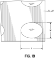
- Each of the first and second pieces of fabric 22, 24 is made of nonwoven spunlaced aperture fabric having a pattern of apertures 25 therethrough which allow air to flow quickly through the fabric.
- One of the apertures 25 is shown in detail in Fig. 18 .
- the fabric pieces 22, 24 are joined together with circular containments or weld seams 30, each weld seam 30 surrounding a mini coil spring 28.
- Each weld seam 30 comprises multiple arced or curved weld segments 26 with gaps 31 therebetween.
- the first and second pieces of fabric 22, 24 are joined together along each arced or curved weld segment 26 of each circular weld seam 30.
- the first and second pieces of fabric 22, 24 are not joined together along each gap 31 between adjacent weld segments 26 of each circular weld seam 30.
- the curved weld segments 26 are strategically placed around a mini coil spring 28 and create the circular weld seam 30.
- the two pieces of fabric 22, 24, in combination with one of the circular weld seams 30, define a cylindrical-shaped pocket 44, inside of which is at least one mini coil spring 28. See Figs. 5 and 5A .
- the mini coil springs 28 may be at least partially compressed before pocket 44 is closed and thereafter.
- resilient members other than mini coil springs such as foam members, may be used.
- resilient members made of other resilient material(s), including those partially made of foam, which return to an original configuration after a load is removed from the material, may be used inside the pockets.
- the weld segments may assume shapes other than the curved weld segments illustrated.
- the welds or seams may be circular around mini coil springs, but the weld segments may assume other shapes, such as triangles or circles or ovals of the desired size and pattern to obtain the desired airflow between adjacent pockets inside the comfort layer and into or out of the perimeter of the comfort layer.
- the focus of the present invention is on the fabric which makes up at least one of the first and second pieces of fabric 22, 24.
- the drawings show the first and second pieces of fabric 22, 24 being identical, it is within the scope of the present invention that only one of the first and second pieces of fabric 22, 24 be the aperture fabric shown in the drawings.
- each of the apertures 25 shown throughout each of the first and second pieces of fabric 22, 24 has an oval-shape comprising a length "L” and a width "W” in a relaxed condition.
- Some fabrics which have proven satisfactory are available from Hangzhou Nbond Nonwoven Company, Limited of China. These fabrics include a nonwoven spunlaced aperture fabric having four apertures per square centimeter in which the length dimension "L” is three (3) millimeters and the width dimension "W" is 2.5 millimeters.
- This fabric is known in the industry as a four-mesh fabric.
- at least one of the fabrics (22, 24) is a four-mesh fabric.
- Another fabric from the same supplier is a nonwoven spunlaced aperture fabric having eight apertures per square centimeter in which the length dimension "L” is three millimeters and the width dimension "W” is one millimeter.
- This fabric is known in the industry as an eight-mesh fabric.
- Another fabric from the same supplier is a nonwoven spunlaced aperture fabric having twenty apertures per square centimeter in which the length dimension "L” is 1.2 millimeters and the width dimension "W” is 0.7 millimeter.
- This fabric is known in the industry as a twenty-mesh fabric.
- Another fabric from the same supplier is a nonwoven spunlaced aperture fabric having twenty-two apertures per square centimeter in which the length dimension "L” is 0.8 millimeters and the width dimension "W” is 0.4 millimeter.
- This fabric is known in the industry as a twenty-two mesh fabric.
- Each of the first and second pieces of fabric 22, 24 preferably has a fabric weight of between 45 grams per square meter and 150 grams per square meter, but may have any desired fabric weight. Any of these nonwoven spunlaced aperture fabrics is said to be vented and allows air to flow freely though the material while still providing enough surface area to glue one piece of the nonwoven spunlaced aperture fabric to another surface, such as a surface of a foam piece of a surface of a pocketed spring assembly.
- the nonwoven spunlaced aperture fabric In order to be weldable to itself, the nonwoven spunlaced aperture fabric must be made of at least 50 percent synthetic fibers, such as polyester fibers, including polyethylene terephthalate (PET) fibers.
- the other fibers in the fabric may be made of viscose fibers, bamboo, Tencel, cotton, nylon, bio-component fiber, polylactic acid (“PLA”) fiber, rayon or wood pulp or any combination thereof.
- a portion of a mobile ultrasonic welding horn 32 and anvil 42 there is illustrated a portion of a mobile ultrasonic welding horn 32 and anvil 42.
- the movable ultrasonic welding horn 32 has a plurality of spaced cut-outs or slots 34 along its lower edge 36.
- the remaining portions 38 of the ultrasonic welding horn's bottom 36 between the slots 34 are the portions which weld the two pieces of fabric 22, 24 together and create the curved weld segments 26.
- the ultrasonic welding horn 32 can be milled to make the slots a desired length to allow a desired airflow between the curved weld segments 26 as illustrated by the arrows 40 of Fig. 5 .
- the airflows affect the feel/compression of the individually pocketed mini coil springs 28 when a user lays on the mattress 10.
- anvil 42 comprising a steel plate of 3/8 th inch thickness.
- the anvil may be any desired thickness.
- the ultrasonic welding horn 32 contacts the anvil 42, the two pieces of fabric 22, 24 therebetween, to create the circular weld seams 30 and, hence, cylindrical-shaped pockets 44, at least one mini coil spring being in each pocket 44.
- These curved weld segments 26 are created by the welding horn 32 of a machine (not shown) having multiple spaced protrusions 38 on the ultrasonic welding horn 32.
- the pieces 22, 24 define a plurality of spring-containing pockets 44 of the comfort layer 16.
- One or more mini coil springs 28 may be contained within an individual pocket 44.
- Fig. 4A illustrates another apparatus for forming the circular weld seams 30 comprising multiple curved weld segments 26 having gaps 31 therebetween for airflow.
- the ultrasonic welding horn 32a has no protrusions on its bottom surface 39. Instead, the bottom surface 39 of ultrasonic welding horn 32a is smooth.
- the anvil 42a has a plurality of curved projections 41, which together form a projection circle 43.
- a plurality of projection circles 43 extend upwardly from the generally planar upper surface 45 of anvil 42a.
- a circular weld seam 30 is created, as described above.
- a plurality of pockets 44 are created by the circular weld seams 30, each pocket 44 containing at least one mini coil spring 28.
- a pocket 44 containing at least one mini coil spring 28 is compressed by compressing the mini coil spring(s) 28 and air contained within the pocket 44. Air exits the pocket 44 through apertures 25 in the fabric and gaps 31 between the curved weld segments 26 of the circular weld seams 30.
- the mini coil spring 28 separates the fabric layers 22, 24, and air reenters the pocket 44 though apertures 25 in the fabric and through the gaps 31 between the curved weld segments 26 of the circular weld seams 30.
- the size of the gaps 31 between the segments 26 of circular seams 30 of perimeter pockets 44 may affect how quickly air may enter or exit the comfort layer 16.
- the fabric material is permeable to airflow, so the rate at which the mini coil springs 28 compress when a load is applied to a pocketed spring core comfort layer 16 is not slowed or retarded by the air entrapped within the individual pockets as the pocketed spring comfort layer 16 is compressed. Similarly, the rate of return of the compressed coil spring comfort layer to its original height after compression is not retarded or slowed by the rate at which air may pass through the permeable fabric material into the interior of the individual pockets 44 of the pocketed spring comfort layer 16. Air passes through the apertures in the first and second pieces of fabric 22, 24 when the pocket 44 is compressed and when the pocket 44 is unloaded, enlarging or expanding due to the inherent characteristics of the mini springs 28. In addition, air passes through the gaps 31 between the curved weld segments 26 of the circular weld seams 30, as described above.
- the individual pockets 44 of comfort layer 16 may be arranged in longitudinally extending columns 46 extending from head-to-foot of the bedding product and transversely extending rows 48 extending from side-to-side of the bedding product. As shown in Figs. 5 and 5A , the individual pockets 44 of one column 46 are aligned with the pockets 44 of adjacent columns 46.
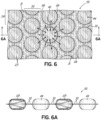
- Figs. 6 and 6A illustrate another comfort layer 50 having the same pockets 44 and same springs 28 as does the embodiment of comfort layer 16 of Figs. 1-5A .
- the individual pockets 44 of comfort layer 50 are arranged in longitudinally extending columns 52 extending from head-to-foot of the bedding product and transversely extending rows 54 extending from side-to-side of the bedding product.
- the individual pockets 44 of one column 52 are offset from, rather than aligned with, the pockets 44 of the adjacent columns 52.
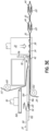
- Fig. 7 illustrates an alternative embodiment of comfort layer 56 incorporated into a single-sided mattress 60.
- Single-sided mattress 60 comprises a pocketed spring core 62, a cushioning pad 14 on top of the pocketed spring core 62, a base 18, another cushioning pad 14 above comfort layer 56, and an upholstered covering material 20.
- Pocketed spring core 62 may be incorporated into any bedding or seating product, including a double-sided mattress, and is not intended to be limited to single-sided mattresses.
- comfort layer 56 may be used in any conventional core, including a spring core made with non-pocketed conventional springs, such as coil springs.
- mattress 60 has a longitudinal dimension or length L, a transverse dimension or width W and a height H.
- length L is shown as being greater than the width W, they may be identical.
- the length, width and height may be any desired distance and are not intended to be limited by the drawings.
- Fig. 9 illustrates the components of the comfort layer 56 incorporated into the mattress 60 shown in Fig. 7 .
- the comfort layer 56 comprises a first piece of fabric 64 and a second piece of fabric 66 joined together with multiple linear weld segments 68.
- the first and second pieces of fabric 64, 66 are made of the same nonwoven spunlaced aperture fabric described herein with respect to first and second pieces of fabric 22, 24.
- Each of the first and second pieces of fabric 64, 68 is made of nonwoven spunlaced aperture fabric having a pattern of apertures 25 therethrough which allow air to flow quickly through the fabric.
- One of the apertures 25 is shown in detail in Fig. 18 .
- the weld segments 68 are strategically placed around a mini coil spring 28 and create a rectangular containment or seam 70. During the welding process, the mini coil springs 28 may be compressed.
- the length and/or width of the linear weld segments 68 of seams 70 is not intended to be limited to those illustrated; they may be any desired size depending upon the airflow desired through the comfort layer. Similarly, the size of the illustrated seams 70 is not intended to be limiting. Shapes other than linear weld segments may be used to create rectangular seams. Such shapes may include, but are not limited to, triangles or circles or ovals of any desired size and pattern to obtain the desired airflow between adjacent pockets and into or out of the perimeter of the comfort layer.
- a portion of an ultrasonic welding horn 72 and anvil 74 there is illustrated a portion of an ultrasonic welding horn 72 and anvil 74.
- the mobile or movable ultrasonic welding horn 72 has a plurality of spaced cut-outs or slots 76 between projections 80.
- the projections 80 of the ultrasonic welding horn 72 are the portions which weld the two pieces of fabric 64, 66 together and create the linear weld segments 68 in rectangular weld seams 70.
- the ultrasonic welding horn 72 can be milled to allow a desired airflow between the linear weld segments 68 as illustrated by the arrows 82 of Fig. 7 .
- the airflows affect the feel/compression of the individually pocketed mini coil springs 28 when a user lays on the mattress 60.
- anvil 74 comprising a steel plate of 3/8 th inch thickness.
- the anvil may be any desired thickness.
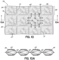
- the ultrasonic welding horn 72 contacts the anvil 74, the two pieces of fabric 64, 66 being therebetween, to create the rectangular weld seams 70 and, hence, pockets 84, at least one mini coil spring 28 being in each pocket 84. See Figs. 10 and 10A .
- linear weld segments 68 may be created by the welding horn 72 of a machine (shown in Fig. 8 and described below) having multiple spaced protrusions 80 on the ultrasonic welding horn 72.
- each mini coil spring 28 is contained within its own individual pocket 84. Air exits the pocket 84 through gaps 77 between the weld segments 68 of the rectangular weld seams 30.
- the mini coil spring 28 separates the fabric layers 64, 66, and air reenters the pocket 84 though the gaps 77 between the weld segments 68 of the rectangular weld seams 70.
- the size of the gaps 77 between the segments 68 of rectangular weld seams 70 of the pockets 84 may assist how quickly air may enter or exit the comfort layer 56.
- Fig. 9A illustrates another apparatus for forming the rectangular weld seams 70 comprising multiple linear weld segments 68 having gaps 77 therebetween for airflow.
- the ultrasonic welding horn 72a has no protrusions on its bottom surface 79. Instead, the bottom surface 79 of ultrasonic welding horn 72a is smooth.
- the anvil 74a has a plurality of linear projections 71, which together form a projection pattern 73, shown in Fig. 9A .
- a plurality of spaced projections 71 in pattern 73 extend upwardly from the generally planar upper surface 75 of anvil 74a.
- one fabric material permeable to airflow which may be used in either of the two pieces of the pocketed spring comfort layers disclosed or shown herein, may be a nonwoven spunlaced aperture fabric with apertures 25.
- the individual pockets 84 of comfort layer 56 may be arranged in longitudinally extending columns 86 extending from head-to-foot of the bedding product and transversely extending rows 88 extending from side-to-side of the bedding product. As shown in Figs. 10 and 10A , the individual pockets 84 of one column 86 are aligned with the pockets 84 of the adjacent columns 86. Air may flow between pockets 84 and into and out of the comfort layer 56 between the linear segments 68 of seams 70.
- Fig. 11 illustrates one corner of comfort layer 16 of mattress 10 showing airflow between the curved weld segments 26 of the peripheral pockets 44, as illustrated by the arrows 40.
- Fig. 11 illustrates the arrows 40 only on one corner pocket 44
- each of the pockets 44 around the periphery of the comfort layer 16 allows airflow through the gaps 31 between the weld segments 26 of circular seams 30. This airflow affects the amount of air entering the comfort layer 16 when a user changes position or gets off the bedding or seating product, thus allowing the springs 28 in the pockets 44 to expand and air to flow into the comfort layer 16.
- the springs 28 compress and cause air to exit the pockets 44 around the periphery of the comfort layer 16 and exit the comfort layer.
- the amount of air exiting the comfort layer 16 affects the feel/compression of the individually pocketed mini coil springs 28 when a user lays on the mattress 10.
- Fig. 11A illustrates one corner of comfort layer 56 of mattress 60 of Fig. 7 showing airflow between the weld segments 68 of the peripheral pockets 84, as illustrated by the arrows 82.
- Fig. 11A illustrates the arrows 82 only on one corner pocket 84
- each of the pockets 84 around the periphery of the comfort layer 56 allows airflow through the gaps 77 between the weld segments 68 of rectangular seams 70. This airflow affects the amount of air entering the comfort layer 56 when a user changes position or gets off the bedding or seating product, thus allowing the springs 28 in the pockets 84 to expand and air to flow into the comfort layer 56.
- the springs 28 compress and cause air to exit the pockets 84 around the periphery of the comfort layer 16 and exit the comfort layer.
- the amount of air exiting the comfort layer 56 affects the feel/compression of the individually pocketed mini coil springs 28 when a load is applied to the mattress 10.
- Fig. 12 illustrates one corner of an alternative embodiment of comfort layer 16a, which may be used in any bedding or seating product.
- the comfort layer 16a comprises aligned rows 48 and columns 46 of pockets 44a, each pocket 44a comprising a circular seam 30a joining upper and lower plies of fabric, as described above.
- each of the circular seams 30a is a continuous seam, as opposed to a seam having curved weld segments with gaps therebetween to allow airflow through the circular seam.
- These circular seams 30a of pockets 44a allow no airflow through the seams 30a. Therefore, the fabric material of the first and second plies of pockets 44a of comfort layer 16a must be made of permeable material to allow airflow into and out of the pockets 44a of comfort layer 16a.
- comfort layer 16a solely controls the amount of air entering the comfort layer 16a when a user gets off the bedding or seating product, thus allowing the springs 28 in the pockets 44a to expand and air to flow into the comfort layer 16a. Similarly, when a user gets onto a bedding or seating product, the springs 28 compress and cause air to exit the pockets 44a of the comfort layer 16a and exit the comfort layer. The amount of air exiting the comfort layer 16a affects the feel/compression of the individually pocketed mini coil springs 28 when a user lays on the product incorporating the comfort layer 16a.
- Fig. 12A illustrates one corner of an alternative embodiment of comfort layer 56a, which may be used in any bedding or seating product.
- the comfort layer 56a comprises aligned rows 88 and columns 86 of pockets 84a, each pocket 84a comprising a rectangular seam 70a joining upper and lower plies of fabric as described above.
- each of the rectangular seams 70a is a continuous seam, as opposed to a seam having weld segments with gaps therebetween to allow airflow through the seam.
- These rectangular seams 70a of pockets 84a allow no airflow through the seams 70a. Therefore, the fabric material of the first and second plies of pockets 84a of comfort layer 56a must be made of permeable material to allow airflow into and out of the pockets 84a of comfort layer 56a.
- comfort layer 56a solely controls the amount of air entering the comfort layer 56a when a user gets off the bedding or seating product, thus allowing the springs 28 in the pockets 84a to expand and air to flow into the comfort layer 56a. Similarly, when a user gets onto a bedding or seating product, the springs 28 compress and cause air to exit the pockets 84a of the comfort layer 56a and exit the comfort layer. The amount of air exiting the comfort layer 56a affects the feel/compression of the individually pocketed mini coil springs 28 when a user lays on the product incorporating the comfort layer 56a.
- Fig. 2 illustrates a machine 90 used to make several of the comfort layers shown and disclosed herein, including comfort layer 16 shown in Fig. 1 . Some parts of the machine 90 may be changed to make other comfort layers shown or described herein, such as comfort layer 56 shown in Fig. 7 .
- Machine 90 comprises a pair of ultrasonic welding horns 32, and at least one stationary anvil 42, as shown in Fig. 4 . Alternatively, ultrasonic welding horns 32a and anvil 42a of Fig. 4A may be used in the machine.
- Machine 90 discloses a conveyor 92 on which are loaded multiple mini coil springs 28.
- the conveyor 92 moves the mini coil springs 28 in the direction of arrow 94 (to the right as shown in Fig. 2 ) until the mini coil springs 28 are located in predetermined locations, at which time the conveyor 92 stops moving.
- Machine 90 further discloses several actuators 96, which move a pusher assembly 97, including a pusher plate 98 in the direction of arrow 100. Although two actuators 96 are illustrated in Figs. 2 and 2A , any number of actuators 96 of any desired configuration may be used to move the pusher assembly 97.
- the pusher plate 98 has a plurality of spaced spring pushers 102 secured to the pusher plate 98 underneath the pusher plate 98.
- the spring pushers 102 push the mini coil springs 28 between stationary guides 104 from a first position shown in Fig. 2 to a second position shown in Fig. 4 in which the mini coil springs 28 are located above the stationary anvil 42 (or above the alternative anvil 42a shown in Fig. 4A ).
- Fig. 2A illustrates the mini coil springs 28 being transported from the first position to the second position, each mini coil spring 28 being transported between adjacent stationary guides 104.
- the stationary guides 104 are secured to a stationary mounting plate 106.
- the machine 90 further comprises a compression plate 108, which is movable between raised and lowered positions by lifters 110. Although two lifters 110 are illustrated in Figs. 2 and 2A , any numbers of lifters 110 of any desired configuration may be used to move the compression plate 108.
- machine 90 further comprises three pressers 112 movable between raised and lowered positions via actuators 116.
- Figs. 3B and 3C show one of the pressers 112 in a raised position
- Figs. 3A , 3D and 3E show the presser in a lowered position.
- Each presser has a blade 114 at the bottom thereof for bringing the plies 22, 24 of fabric together when the presser is lowered, as shown in Figs. 3A , 3D and 3E .
- machine 90 further comprises rollers 120, 122 around which the plies, 22, 24 respectively pass before they come together.
- a main roller 116 and secondary roller 118 pull the continuous spring blanket 124 downwardly.
- a blade 126 cuts the continuous spring blanket 120 to create comfort layer 16 of the desired size.
- the machine 90 may be programmed to create the desired length and width of comfort layer. This machine 90 is adapted to make any of the comfort layers shown or disclosed herein having circular weld seams.
- Fig. 3A illustrates the ultrasonic welding horn 32 in a lowered position contacting the stationary anvil 42 with at least one of the pressers 112 in a lowered position pressing the upper ply 22 into contact with the lower ply 24.
- a new row of mini coil springs 28 has been moved into a loading position with the compression plate 108 in its raised position.
- Fig. 3B illustrates the ultrasonic welding horn 32 in a raised position spaced from the anvil 42 with at least one of the pressers 112 in a raised position.
- the compression plate 108 is moved to its lowered position by lifters 110, thereby compressing the row of mini coil springs 28 located on the conveyor 92.
- Fig. 3C illustrates the row of compressed mini coil springs 28 located on the conveyor 92 being pushed downstream towards the ultrasonic welding horn 32 and stationary anvil 42 by the pusher assembly 97. More particularly, the pushers 102 secured to the pusher plate 98 contact the compressed mini coil springs 28 and move them downstream between the stationary guides 104 and past the raised pressers 112.
- Fig. 3D illustrates the pusher assembly 97 being withdrawn in the direction of arrow 128. Additionally, the pressers 112 are moved to a lowered position pressing the upper ply 22 into contact with the lower ply 24. Also, the compression plate 108 is moved to its raised position by lifters 110.
- Fig. 3E illustrates the ultrasonic welding horn 32 in a lowered position contacting the stationary anvil 42 with at least one of the pressers 112 in a lowered position pressing the upper ply 22 into contact with the lower ply 24.
- a new row of mini coil springs 28 has been moved by the conveyor 92 into a position in which they may be compressed with the compression plate 108 during the next cycle.
- Fig. 8 illustrates a machine 130, like the machine 90 shown in Figs. 2 and 2A .
- machine 130 instead of having two ultrasonic welding horns 32, machine 130 has four ultrasonic welding horns 72 along with anvil 74.
- ultrasonic welding horns 72a and anvil 74a of Fig. 9A may be used in machine 130.
- This machine 130 is adapted to make any of the comfort layers shown or disclosed herein having rectangular weld seams, as opposed to circular weld seams.
- Fig. 13A illustrates a posturized comfort layer 132 having three different areas or regions of firmness depending upon the airflow within each of the areas or regions.
- the comfort layer 132 has a head section 134, a foot section 136 and a lumbar or middle section 138 therebetween.
- the size and number of segments in the seams, along with the type of material used to construct the posturized comfort layer 132, may be selected so at least two of the sections may have a different firmness due to different airflows within different sections.
- three sections are illustrated in Fig. 13A , any number of sections may be incorporated into a posturized comfort layer.
- each of the sections is illustrated being a certain size, they may be other sizes.
- the drawings are not intended to be limiting.
- Fig. 13A shows each of the segmented seams of comfort layer 132 being circular, a posturized comfort layer, such as the one shown in Fig. 13A , may have rectangular or square segmented seams.
- Fig. 13B illustrates a posturized comfort layer 140 having two different areas or regions of firmness depending upon the airflow within each of the areas or regions.
- the comfort layer 140 has a first section 142 and a second section 144.
- the size and number of segments in the seams, along with the type of material used to construct the posturized comfort layer 140, may be selected so at least two of the sections may have a different firmness due to different airflows within different sections.
- two sections are illustrated in Fig. 13B , any number of sections may be incorporated into a posturized comfort layer.
- each of the sections is illustrated being a certain size, they may be other sizes.
- the drawings are not intended to be limiting.
- Fig. 13B shows each of the segmented seams of comfort layer 140 being circular, a posturized comfort layer, such as the one shown in Fig. 13B , may have rectangular or square segmented seams.
- Fig. 14 illustrates a web or blanket 150 of comfort layer like the blanket 124 described above and shown in Figs. 2 and 2A moving in the direction of arrow 152.
- the blanket 150 has a lesser density of individually pocketed mini coil springs than blanket used to make the comfort layers shown in the other drawings.
- spaced rows 154 of pocketed mini coil springs 156 extend in a direction perpendicular to the direction of travel of the blanket 150 during manufacture.
- the spaced rows 154 are spaced between spaced areas 158 which contain no pocketed mini coil springs.
- the spaced areas 158 may be the same size as the rows 154 so every other row of pocketed mini coil springs is missing or omitted.
- the spaced areas 158 may be any desired size. Due to the spacing between rows 154 extending from side-to-side, the pocketed mini coil springs 156 form columns 155 extending parallel the direction of travel of the blanket 150 during manufacture. Each column 155 comprises pocketed mini coil springs 156 spaced from each other a distance equal to or greater than the diameter of one circular weld seam 170.
- the circular weld seams 170 may be segments or solid.
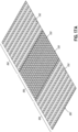
- Fig. 14A illustrates another web or blanket 160 of comfort layer moving in the direction of arrow 162.
- the blanket 160 has a lesser density of individually pocketed mini coil springs than blanket used to make the comfort layers shown in the drawings other than Fig. 14 .
- spaced columns 164 of pocketed mini coil springs 156 extend in a direction parallel the direction of travel of the blanket 160 during manufacture.
- the spaced columns 164 are spaced between spaced areas 168 which contain no pocketed mini coil springs.
- the spaced areas 168 may be the same size as the columns 164. However, the spaced areas 168 may be any desired size.
- each row 165 comprises pocketed mini coil springs 156 spaced from each other a distance equal to or greater than the diameter of one circular weld seam 170.
- FIGs. 14 and 14A illustrate pocketed mini coil springs 156 having circular weld seams 170, rectangular weld seams as described herein may be incorporated into the pocketed mini coil springs of Figs. 14 and 14A .
- the drawings show the blankets 150, 160 made with nonwoven spunlaced aperture fabric, any fabric described or shown herein may be used to form blankets 150, 160.
- Figs. 15 and 15A illustrate enlarged views of a portion of the blanket 160.
- the circular weld seams 170 are segmented having gaps 31 between curved weld segments 26, like the circular weld seams 30.
- Figs. 15 and 15A show at least one mini coil spring 28 being in each pocket 171 formed by one of the circular weld seams 170.
- Arrows 40 illustrate airflow between the curved weld segments 26 into and out of the pockets 171.
- Figs. 16 and 16A illustrate enlarged views of a portion of another blanket 160a having rectangular weld seams 172 rather than circular weld seams.
- the rectangular weld seams 172 are segmented having gaps 174 between straight weld segments 176, like the rectangular weld seams 70.
- Figs. 16 and 16A show at least one mini coil spring 28 being in each pocket 175 formed by one of the rectangular weld seams 172.
- Arrows 82 illustrate airflow between the straight weld segments 176 into and out of the pockets 175.
- Fig. 17A illustrates a posturized comfort layer 180 having three areas or regions of differing firmness depending upon the density of pockets within each of the areas or regions.
- the comfort layer 180 has a head section 182, a foot section 184 and a lumbar or middle section 186 therebetween.
- the number of pockets in the sections may be selected so at least two of the sections may have a different firmness.
- three sections are illustrated in Fig. 17A , any number of sections may be incorporated into a posturized comfort layer. Although each of the sections is illustrated being a certain size, they may be other sizes.
- the drawings are not intended to be limiting. Head and foot sections 182, 184 may have the same firmness due to having the same density of individually pocketed mini coil springs 192.
- Fig. 17A shows each of the number of individually pocketed mini coil springs 190 in the middle section 186 being greater than the number of individually pocketed mini coil springs 192 in the head and foot sections 182, 184, the opposite may be true.
- Any comfort layer may be posturized by having more or less individually pocketed mini coil springs in one section when compared to another section.
- Fig. 17A shows solid circular weld seams and associated pockets, the circular weld seams may be segmented.
- a posturized comfort layer such as the one shown in Fig. 17A , may have rectangular or square weld seams with either segmented or solid weld seams.
- Fig. 17B illustrates a posturized comfort layer 200 having two different areas or regions of firmness depending upon the density of individually pocketed mini coil springs 194 within each of the areas or regions.
- the comfort layer 200 has a first section 202 and a second section 204.
- the number of individually pocketed mini coil springs 194 may have different firmness due to different pocketed densities within different sections.
- two sections are illustrated in Fig. 17B , any number of sections may be incorporated into a posturized comfort layer. Although each of the sections is illustrated being a certain size, they may be other sizes.
- the drawings are not intended to be limiting.
- Fig. 17B shows solid circular weld seams and associated pockets, the circular weld seams may be segmented.
- a posturized comfort layer such as the one shown in Fig. 17B , may have rectangular or square weld seams with either segmented or solid weld seams.
- Fig. 17A and 17B show the first and second pieces of fabric being nonwoven spun laced aperture fabric
- any known fabric may be used in accordance with the posturized comfort layers having sections of different firmness due to the density of the individually pocketed mini coil springs.
- each pocket may contain any number of coil springs or other type of spring, made of any desired material.
- the segments of the weld seams may be stitched, glued or otherwise adhered or bonded. Therefore, we do not intend to be limited except by the scope of the following appended claims.
Landscapes
- Mattresses And Other Support Structures For Chairs And Beds (AREA)
Claims (14)
- Komfortschicht (16, 50, 56, 16a, 56a, 132, 140, 150, 160, 160a, 180, 200), die ausgestaltet ist, um einen Federkern eines Bettwaren- oder Sitzkissenprodukts (10) zu überdecken, wobei die Komfortschicht umfasst:eine Matrix aus in Taschen befindlichen Minischraubenfedern (28), von denen jede Minischraubenfeder (28) in einer Tasche (44, 84, 44a, 84a, 171, 175) enthalten ist, wobei die Tasche für einen Luftstrom durch die Tasche durchlässig ist und eine Naht (30, 70, 30a, 70a, 170, 172) um die Tasche herum aufweist, die ein erstes und ein zweites Stoffstück (22, 24, 64, 66) der Tasche verbindet;wobei mindestens eines der Stoffstücke (22, 24, 64, 66) aus einem Vliesstoff mit Öffnungen besteht, um die Geschwindigkeit zu erhöhen, mit der Luft durch den Stoff der Tasche entweicht, wenn eine Last auf die Tasche aufgebracht wird,wobei eine Kompressionsgeschwindigkeit der Minischraubenfedern, die der Last ausgesetzt sind, durch Öffnungen (25) in dem Stoff erhöht wird,wobei mindestens eines der Stoffstücke ein Vier-Maschen- oder ein Acht-, Zehn-, Zwanzig- oder Zweiundzwanzig-Maschen-Stoff ist, wobei der Vier-Maschen-Stoff ein Spinnvliesstoff mit vier Öffnungen pro Quadratzentimeter ist, wobei jede der Öffnungen (25) in einem entspannten Zustand eine ovale Form aufweist, bei der die Längenabmessung 3 Millimeter und die Breitenabmessung 2,5 Millimeter beträgt.
- Komfortschicht nach Anspruch 1, wobei mindestens eines der Stoffstücke (22, 24, 64, 66) zumindest teilweise aus Polyester besteht.
- Komfortschicht nach Anspruch 1 oder Anspruch 2, wobei mindestens eines der Stoffstücke (22, 24, 64, 66) ein Stoffgewicht zwischen 45 Gramm pro Quadratmeter und 150 Gramm pro Quadratmeter aufweist.
- Komfortschicht nach einem der Ansprüche 1-3, wobei mindestens eines der Stoffstücke (22, 24, 64, 66) ein Stoff mit einer Maschengröße von zehn Maschen ist.
- Komfortschicht nach einem der Ansprüche 1-4, wobei die Taschen (44, 84, 44a, 84a, 171, 175) in voneinander beabstandeten Reihen angeordnet sind.
- Komfortschicht nach einem der Ansprüche 1-5, wobei jede Naht (30, 70, 170, 172) mehrere Segmente (26, 68, 176) umfasst.
- Komfortschicht nach einem der Ansprüche 1-6, wobei:das erste Stoffstück (22, 64) ein erstes Stück eines Vliesstoffs mit Öffnungen ist, das für einen Luftstrom durch den Stoff durchlässig ist und das auf einer Seite der Matrix aus Minischraubenfedern (28) angeordnet ist; unddas zweite Stoffstück (24, 66) ein zweites Stück eines Vliesstoffs mit Öffnungen ist, das für einen Luftstrom durch den Stoff durchlässig ist und das auf einer anderen Seite der Matrix aus Minischraubenfedern (28) angeordnet ist,wobei die Komfortschicht (16, 50, 56, 16a, 56a, 132, 140, 150, 160, 160a, 180, 200) ausgestaltet ist, so dass, wenn zumindest einige der Minischraubenfedern (28) in zumindest einigen der Taschen (44, 84, 44a, 84a, 171, 175) einer Last ausgesetzt sind, sich Luft durch die Öffnungen (25) in dem Gewebe bewegt, wobei die Kompressionsrate der Minischraubenfedern (28) durch die Öffnungen (25) in dem Gewebe erhöht wird.
- Komfortschicht nach Anspruch 7, wobei die Rückstellgeschwindigkeit der Minischraubenfedern (28) in den Taschen (44, 84, 44a, 84a, 171, 175) durch die Öffnungen (25) in dem ersten und dem zweiten Stoffstück (22, 24, 64, 66) erhöht wird.
- Komfortschicht nach Anspruch 7 oder Anspruch 8, wobei die Nähte (30, 70, 30a, 70a, 170, 172) kreisförmig oder rechteckförmig sind.
- Komfortschicht nach einem der Ansprüche 1-5, wobei:das erste Stoffstück (22, 64) ein erstes Stück eines Vliesstoffs mit Öffnungen auf einer Seite der Minischraubenfedern (28) ist; unddas zweite Stoffstück (24, 66) ein zweites Stück eines Vliesstoffs mit Öffnungen auf einer anderen Seite der Minischraubenfedern (28) ist, wobei das erste und das zweite Stoffstück (22, 24, 64, 66) mit den Nähten (30, 70, 170, 172) verbunden sind, die beabstandete Segmente (26, 68, 176), die jede der Minischraubenfedern (28) umgeben, um Lücken (31, 77, 174) zwischen den Segmenten und den einzelnen Taschen (44, 84, 44a, 84a, 171, 175) zu schaffen, die die Minischraubenfedern (28) enthalten, umfassen, wobei das erste und das zweite Stoffstück (22, 24, 64, 66) für einen Luftstrom durch die Öffnungen (25) in dem Stoff durchlässig sind,wobei die Komfortschicht (16, 50, 56, 16a, 56a, 132, 140, 150, 160, 160a, 180, 200) ausgestaltet ist, so dass, wenn zumindest einige der Taschen (44, 84, 44a, 84a, 171, 175) einer Last ausgesetzt sind, sich Luft schnell aus den Taschen durch die Öffnungen (25) in dem ersten und in dem zweiten Stoffstück (22, 24, 64, 66) und zwischen den Segmenten (26, 68, 176) der Nähte (30, 70, 170, 172) bewegt, wobei die Kompressionsrate der Minischraubenfedern (28) durch die Öffnungen (25) in dem ersten und in dem zweiten Stoffstück (22, 24, 64, 66) und die Lücken (31, 77, 174) zwischen den Segmenten (26, 68, 176) der Nähte (30, 70, 170, 172) erhöht wird.
- Komfortschicht nach Anspruch 10, wobei die Nähte (70, 172) rechteckförmig sind.
- Komfortschicht nach Anspruch 10 oder Anspruch 11, wobei die Stoffstücke (22, 24, 64, 66) dieselbe Maschenweite aufweisen.
- Komfortschicht nach einem der Ansprüche 1-12, wobei die Minischraubenfedern (28) in entspanntem Zustand etwa zwischen 1,90 und 6,35 cm (0,75 und 2,5 Zoll) hoch sind.
- Komfortschicht nach einem der Ansprüche 1-13, wobei zumindest einige der Minischraubenfedern (28) eine Tonnenform aufweisen.
Applications Claiming Priority (2)
| Application Number | Priority Date | Filing Date | Title |
|---|---|---|---|
| US16/548,958 US11033116B2 (en) | 2019-08-23 | 2019-08-23 | Dual-sided vented pocketed spring comfort layer |
| PCT/US2020/043938 WO2021040949A1 (en) | 2019-08-23 | 2020-07-29 | Dual-sided vented pocketed spring comfort layer |
Publications (3)
| Publication Number | Publication Date |
|---|---|
| EP4017323A1 EP4017323A1 (de) | 2022-06-29 |
| EP4017323A4 EP4017323A4 (de) | 2023-08-30 |
| EP4017323B1 true EP4017323B1 (de) | 2024-12-25 |
Family
ID=74646971
Family Applications (1)
| Application Number | Title | Priority Date | Filing Date |
|---|---|---|---|
| EP20856894.9A Active EP4017323B1 (de) | 2019-08-23 | 2020-07-29 | Zweiseitige belüftete taschenfederkomfortlage |
Country Status (5)
| Country | Link |
|---|---|
| US (1) | US11033116B2 (de) |
| EP (1) | EP4017323B1 (de) |
| CN (1) | CN114554912B (de) |
| DK (1) | DK4017323T3 (de) |
| WO (1) | WO2021040949A1 (de) |
Families Citing this family (6)
| Publication number | Priority date | Publication date | Assignee | Title |
|---|---|---|---|---|
| US20210298486A1 (en) * | 2020-03-25 | 2021-09-30 | L&P Property Management Company | Pocketed Spring Assembly |
| US11571075B2 (en) | 2021-04-30 | 2023-02-07 | L&P Property Management Company | Bedding or seating product having topper with at least one thermally enhanced foam component |
| CN115251653B (zh) * | 2021-04-30 | 2023-10-27 | 厦门新技术集成有限公司 | 弹簧包、弹簧垫、家具和制作弹簧包的方法 |
| CN115813147B (zh) * | 2022-02-15 | 2024-03-22 | 厦门新技术集成有限公司 | 弹性垫及具有该弹性垫的家具 |
| PL444782A1 (pl) * | 2023-05-08 | 2024-11-12 | Nestor Springs Spółka Z Ograniczoną Odpowiedzialnością Spółka Komandytowa | Formatka kieszeniowa do materaca, zawierająca w kieszeniach sprężyny baryłkowe |
| US20250331651A1 (en) * | 2024-04-25 | 2025-10-30 | L&P Property Management Company | Method of making string of springs for use in pocketed spring assembly |
Family Cites Families (69)
| Publication number | Priority date | Publication date | Assignee | Title |
|---|---|---|---|---|
| GB167025A (en) | 1920-05-20 | 1921-08-04 | J H Moorhouse And Company Ltd | Improvements in or relating to spring mattresses, and other resilient surfaces |
| US3375156A (en) * | 1963-05-15 | 1968-03-26 | Du Pont | Nonwoven fabrics and method for the production thereof |
| US4234983A (en) | 1978-10-02 | 1980-11-25 | Simmons Company | Thermally welded spring pockets |
| US4451946A (en) | 1981-11-20 | 1984-06-05 | Simmons U.S.A. Corporation | Pocketed spring assembly |
| DE3240783A1 (de) | 1982-11-04 | 1984-05-10 | Angelika 8644 Pressig Kirchner-Carl | Moebelbauteil |
| US4485506A (en) | 1983-04-07 | 1984-12-04 | Simmons U.S.A. Corporation | Coil spring construction |
| US4574099A (en) | 1984-01-20 | 1986-03-04 | Nixon Michael T | Acoustical panels |
| US4594278A (en) | 1984-01-20 | 1986-06-10 | Nixon Michael T | Acoustical panels |
| JP2836877B2 (ja) | 1988-08-05 | 1998-12-14 | スランバーランド・ホールディングス・リミテッド | マットレス等用のばねユニット |
| US5105488A (en) | 1990-04-18 | 1992-04-21 | Simmons Company | Bedding configuration having variable support characteristics |
| US20020025747A1 (en) | 1999-08-20 | 2002-02-28 | Moshe Rock | Windproof and water resistant composite fabric |
| US6154908A (en) | 1998-09-15 | 2000-12-05 | L&P Property Management Company | Bedding or seating product with edge support |
| US6319864B1 (en) | 1999-03-10 | 2001-11-20 | Rbh Designs, Llc | Triple layer, laminated fabric with waterproof, non-breathable inner layer |
| SE517533C2 (sv) | 1999-03-25 | 2002-06-18 | Stjernfjaedrar Ab | Resårmadrass omfattande ett flertal sammankopplade spiralfjädrar, metod för tillverkande av en resårmadrass samt anordning för förspännande av spiralfjädrar |
| FR2795712B1 (fr) | 1999-07-01 | 2001-09-21 | Oniris Sa | Procede de fabrication d'une armature de matelas a ressorts |
| US6602809B1 (en) | 1999-09-21 | 2003-08-05 | Tyco Plastic Services Ag | Laminate composite material |
| US6290800B1 (en) | 1999-12-02 | 2001-09-18 | Steven J. Antinori | Machine for and a method of manufacturing a laminate particularly adapted for bedding, padding, and upholstering |
| US6537930B1 (en) | 2000-05-18 | 2003-03-25 | Tredegar Film Products Corporation | Three-dimensional highly elastic film/non-woven composite |
| US6490744B1 (en) | 2000-11-02 | 2002-12-10 | L&P Property Management Company | Pocketed bedding or seating product with cushioning pads inside pockets |
| GB0100560D0 (en) | 2001-01-09 | 2001-02-21 | Lamination Technologies Ltd | Clothing |
| US6745420B2 (en) | 2001-03-07 | 2004-06-08 | Gualtiero G. Giori | Adjustable foam and coil spring mattress combination |
| US6598251B2 (en) | 2001-06-15 | 2003-07-29 | Hon Technology Inc. | Body support system |
| US6973690B2 (en) | 2002-07-17 | 2005-12-13 | Aero Products International, Inc. | Adjustable inflatable pillow |
| US6883196B2 (en) | 2002-11-27 | 2005-04-26 | Barber Manufacturing Company, Inc. | Encased coil innerspring assembly |
| US6862763B2 (en) | 2002-12-02 | 2005-03-08 | L&P Property Management Company | Pocketed bedding or seating product having pockets of differing heights |
| US20050273938A1 (en) | 2004-06-09 | 2005-12-15 | The Coleman Company, Inc. | Airbed utilizing extruded coils |
| SE530089C2 (sv) | 2004-10-18 | 2008-02-26 | Stjernfjaedrar Ab | Resårmadrass, såsom pocketmadrass, metod för tillverkning av sådan resårmadrass samt anordning för tillverkning av sådan resårmadrass |
| FR2883462B1 (fr) | 2005-03-25 | 2007-06-22 | Cie Financiere Europ De Literi | Matelas a ressorts ensaches |
| JP4361036B2 (ja) | 2005-07-13 | 2009-11-11 | 豊和繊維工業株式会社 | 車両用防音材 |
| US7337485B2 (en) | 2005-08-31 | 2008-03-04 | The Coleman Company, Inc. | Double high airbed utilizing coils |
| GB0519009D0 (en) | 2005-09-17 | 2005-10-26 | Harrison Bedding Ltd | Pocketted spring units |
| US20070137926A1 (en) | 2005-12-15 | 2007-06-21 | Lear Corporation | Acoustical component for enhancing sound absorption properties while preserving barrier performance in a vehicle interior |
| SE529550C2 (sv) | 2006-03-08 | 2007-09-11 | Stjernfjaedrar Ab | Dämpad pocketmadrass samt metod och anordning för tillverkning av en sådan |
| EP1847383A1 (de) | 2006-04-21 | 2007-10-24 | Rieter Technologies AG | Akustischer Verbundkörper und Leichtverkleidungselement mit einer Zweitschale, das einen derartigen Verbundkörper enthält |
| US7914611B2 (en) | 2006-05-11 | 2011-03-29 | Kci Licensing, Inc. | Multi-layered support system |
| US7454810B2 (en) | 2006-06-20 | 2008-11-25 | Wells Thomas J | Divided support mattress |
| US7622406B2 (en) | 2006-10-31 | 2009-11-24 | Jhrg, Llc | Puncture and abrasion resistant, air and water impervious laminated fabric |
| US8474078B2 (en) | 2007-02-07 | 2013-07-02 | L&P Property Management Company | Slow acting pocketed spring core having cushioning material |
| US7636972B2 (en) | 2007-02-07 | 2009-12-29 | L&P Property Management Company | Slow acting pocketed spring core |
| FR2919218B1 (fr) | 2007-07-25 | 2011-12-02 | Faurecia Automotive Ind | Composant moule d'insonorisation,et son procede de fabrication |
| PL2034088T3 (pl) | 2007-09-10 | 2013-04-30 | Gore W L & Ass Gmbh | Tkanina i laminat tkaniny |
| US20090211028A1 (en) | 2008-02-26 | 2009-08-27 | L&P Property Management Company | Adjustable Bed Having Pocketed Coil Spring Assembly Layer |
| US20090222985A1 (en) | 2008-03-06 | 2009-09-10 | L&P Property Management Company | Stackable bedding foundation having pocketed topper |
| JP5266894B2 (ja) | 2008-06-06 | 2013-08-21 | トヨタ紡織株式会社 | カーペット及びその製造方法 |
| FR2942437B1 (fr) | 2009-02-20 | 2012-08-24 | Faurecia Automotive Ind | Ensemble d'insonorisation pour vehicule automobile et element de paroi associe. |
| US20110014406A1 (en) | 2009-07-15 | 2011-01-20 | James Clyde Coleman | Sheet material exhibiting insulating and cushioning properties |
| US8146184B2 (en) | 2009-11-16 | 2012-04-03 | Feng Yi Outdoor Leisure Equipment Enterprise Co., Ltd. | Inflatable cushion having a warming function |
| WO2011116475A1 (en) | 2010-03-25 | 2011-09-29 | Ibco Srl | Breathable coated fabric |
| DE202010005987U1 (de) | 2010-04-22 | 2010-07-08 | W. L. Gore & Associates Gmbh | Textiles Laminat mit einer Barrierelage mit elastischen Eigenschaften |
| US8490232B2 (en) | 2010-06-23 | 2013-07-23 | L&P Property Management Company | Spring core having border wire with generally rectangular cross-section |
| US8918930B2 (en) | 2011-01-04 | 2014-12-30 | Huntleigh Technology Limited | Methods and apparatuses for low-air-loss (LAL) coverlets and airflow units for coverlets |
| JP4828658B1 (ja) | 2011-03-14 | 2011-11-30 | 株式会社タケヒロ | 車両用防音材 |
| KR200462261Y1 (ko) | 2011-06-24 | 2012-09-03 | 코폼라텍스인터내셔널 주식회사 | 매트리스용 마이크로 스프링 |
| US8322487B1 (en) | 2011-08-19 | 2012-12-04 | Milliken & Company | Acoustically coupled non-woven composite |
| FR2979308B1 (fr) | 2011-08-24 | 2013-09-27 | Faurecia Automotive Ind | Ensemble d'insonorisation, notamment pour un vehicule automobile |
| CN103917368B (zh) | 2011-11-01 | 2015-11-25 | 日本戈尔有限公司 | 层合体布帛 |
| US20130174350A1 (en) | 2012-01-10 | 2013-07-11 | Michael Allman | Mattress assemblies and methods employing cloth member(s) thermally bonded to foam side support member(s) to form mattress encasements |
| GB2506104B (en) | 2012-08-10 | 2018-12-12 | Hs Products Ltd | Resilient unit with different major surfaces |
| PL2789267T3 (pl) * | 2013-04-08 | 2016-02-29 | Stjernfjaedrar Ab | Zapakowane w osobne kieszenie sprężyny śrubowe z wkładkami amortyzacyjnymi i materace kieszeniowe sprężynowe z takimi zapakowanymi w kieszenie sprężynami śrubowymi |
| US9345334B2 (en) | 2013-06-19 | 2016-05-24 | L&P Property Management Company | Pocketed spring assembly comprising strings of springs having Y-shaped seams separating adjacent pockets |
| US20150026893A1 (en) | 2013-07-29 | 2015-01-29 | L&P Property Management Company | Mattress Topper Comprising Pocketed Spring Assembly With At Least One Cushioning Layer |
| US10047477B2 (en) | 2014-04-02 | 2018-08-14 | Kraton Polymers U.S. Llc | Textile coating composition |
| US9370252B2 (en) | 2014-06-17 | 2016-06-21 | L&P Property Management Company | Pocketed spring assembly |
| US9943173B2 (en) | 2015-02-13 | 2018-04-17 | L&P Property Management Company | Pocketed spring comfort layer and method of making same |
| US10405665B2 (en) | 2015-02-13 | 2019-09-10 | L&P Property Management Company | Pocketed spring comfort layer and method of making same |
| CN109152487B (zh) * | 2016-03-07 | 2019-11-01 | L&P产权管理公司 | 袋装型弹簧舒适层及其制作方法 |
| US10034553B2 (en) * | 2016-03-07 | 2018-07-31 | L&P Property Management Company | Multi-layered impermeable fabric for use in pocketed spring assembly |
| US10512340B2 (en) | 2017-05-31 | 2019-12-24 | L&P Property Management Company | Pocketed spring assembly comprising strings of springs with tabs |
| US20190269251A1 (en) * | 2018-03-01 | 2019-09-05 | L&P Property Management Company | Posturized Pocketed Spring Comfort Layer |
-
2019
- 2019-08-23 US US16/548,958 patent/US11033116B2/en active Active
-
2020
- 2020-07-29 DK DK20856894.9T patent/DK4017323T3/da active
- 2020-07-29 WO PCT/US2020/043938 patent/WO2021040949A1/en not_active Ceased
- 2020-07-29 EP EP20856894.9A patent/EP4017323B1/de active Active
- 2020-07-29 CN CN202080072615.9A patent/CN114554912B/zh not_active Expired - Fee Related
Also Published As
| Publication number | Publication date |
|---|---|
| CN114554912B (zh) | 2023-01-24 |
| CN114554912A (zh) | 2022-05-27 |
| US11033116B2 (en) | 2021-06-15 |
| US20210052082A1 (en) | 2021-02-25 |
| EP4017323A4 (de) | 2023-08-30 |
| DK4017323T3 (da) | 2025-02-03 |
| EP4017323A1 (de) | 2022-06-29 |
| WO2021040949A1 (en) | 2021-03-04 |
Similar Documents
| Publication | Publication Date | Title |
|---|---|---|
| US10624466B2 (en) | Pocketed spring comfort layer | |
| US10624467B2 (en) | Pocketed spring comfort layer | |
| EP4017323B1 (de) | Zweiseitige belüftete taschenfederkomfortlage | |
| US10973339B2 (en) | Pocketed spring comfort layer having at least one foam layer and method of making same | |
| US10405665B2 (en) | Pocketed spring comfort layer and method of making same | |
| US10667615B2 (en) | Pocketed spring comfort layer and method of making same | |
| US10813462B2 (en) | Pocketed spring comfort layer and method of making same | |
| EP3426100B1 (de) | Taschenfederkomfortschicht | |
| CN115916005B (zh) | 袋装型弹簧舒适层及其制作方法 |
Legal Events
| Date | Code | Title | Description |
|---|---|---|---|
| STAA | Information on the status of an ep patent application or granted ep patent |
Free format text: STATUS: THE INTERNATIONAL PUBLICATION HAS BEEN MADE |
|
| PUAI | Public reference made under article 153(3) epc to a published international application that has entered the european phase |
Free format text: ORIGINAL CODE: 0009012 |
|
| STAA | Information on the status of an ep patent application or granted ep patent |
Free format text: STATUS: REQUEST FOR EXAMINATION WAS MADE |
|
| 17P | Request for examination filed |
Effective date: 20220221 |
|
| AK | Designated contracting states |
Kind code of ref document: A1 Designated state(s): AL AT BE BG CH CY CZ DE DK EE ES FI FR GB GR HR HU IE IS IT LI LT LU LV MC MK MT NL NO PL PT RO RS SE SI SK SM TR |
|
| DAV | Request for validation of the european patent (deleted) | ||
| DAX | Request for extension of the european patent (deleted) | ||
| P01 | Opt-out of the competence of the unified patent court (upc) registered |
Effective date: 20230523 |
|
| A4 | Supplementary search report drawn up and despatched |
Effective date: 20230727 |
|
| RIC1 | Information provided on ipc code assigned before grant |
Ipc: B68G 9/00 20060101ALI20230721BHEP Ipc: A47C 27/06 20060101ALI20230721BHEP Ipc: A47C 27/045 20060101ALI20230721BHEP Ipc: A47C 21/04 20060101AFI20230721BHEP |
|
| GRAP | Despatch of communication of intention to grant a patent |
Free format text: ORIGINAL CODE: EPIDOSNIGR1 |
|
| STAA | Information on the status of an ep patent application or granted ep patent |
Free format text: STATUS: GRANT OF PATENT IS INTENDED |
|
| INTG | Intention to grant announced |
Effective date: 20240510 |
|
| GRAJ | Information related to disapproval of communication of intention to grant by the applicant or resumption of examination proceedings by the epo deleted |
Free format text: ORIGINAL CODE: EPIDOSDIGR1 |
|
| STAA | Information on the status of an ep patent application or granted ep patent |
Free format text: STATUS: REQUEST FOR EXAMINATION WAS MADE |
|
| INTC | Intention to grant announced (deleted) | ||
| GRAP | Despatch of communication of intention to grant a patent |
Free format text: ORIGINAL CODE: EPIDOSNIGR1 |
|
| STAA | Information on the status of an ep patent application or granted ep patent |
Free format text: STATUS: GRANT OF PATENT IS INTENDED |
|
| INTG | Intention to grant announced |
Effective date: 20240808 |
|
| GRAS | Grant fee paid |
Free format text: ORIGINAL CODE: EPIDOSNIGR3 |
|
| GRAA | (expected) grant |
Free format text: ORIGINAL CODE: 0009210 |
|
| STAA | Information on the status of an ep patent application or granted ep patent |
Free format text: STATUS: THE PATENT HAS BEEN GRANTED |
|
| AK | Designated contracting states |
Kind code of ref document: B1 Designated state(s): AL AT BE BG CH CY CZ DE DK EE ES FI FR GB GR HR HU IE IS IT LI LT LU LV MC MK MT NL NO PL PT RO RS SE SI SK SM TR |
|
| REG | Reference to a national code |
Ref country code: GB Ref legal event code: FG4D |
|
| REG | Reference to a national code |
Ref country code: CH Ref legal event code: EP |
|
| REG | Reference to a national code |
Ref country code: DE Ref legal event code: R096 Ref document number: 602020043803 Country of ref document: DE |
|
| REG | Reference to a national code |
Ref country code: IE Ref legal event code: FG4D |
|
| REG | Reference to a national code |
Ref country code: DK Ref legal event code: T3 Effective date: 20250131 |
|
| REG | Reference to a national code |
Ref country code: SE Ref legal event code: TRGR |
|
| REG | Reference to a national code |
Ref country code: LT Ref legal event code: MG9D |
|
| PG25 | Lapsed in a contracting state [announced via postgrant information from national office to epo] |
Ref country code: HR Free format text: LAPSE BECAUSE OF FAILURE TO SUBMIT A TRANSLATION OF THE DESCRIPTION OR TO PAY THE FEE WITHIN THE PRESCRIBED TIME-LIMIT Effective date: 20241225 |
|
| PG25 | Lapsed in a contracting state [announced via postgrant information from national office to epo] |
Ref country code: FI Free format text: LAPSE BECAUSE OF FAILURE TO SUBMIT A TRANSLATION OF THE DESCRIPTION OR TO PAY THE FEE WITHIN THE PRESCRIBED TIME-LIMIT Effective date: 20241225 |
|
| PG25 | Lapsed in a contracting state [announced via postgrant information from national office to epo] |
Ref country code: BG Free format text: LAPSE BECAUSE OF FAILURE TO SUBMIT A TRANSLATION OF THE DESCRIPTION OR TO PAY THE FEE WITHIN THE PRESCRIBED TIME-LIMIT Effective date: 20241225 |
|
| PG25 | Lapsed in a contracting state [announced via postgrant information from national office to epo] |
Ref country code: LV Free format text: LAPSE BECAUSE OF FAILURE TO SUBMIT A TRANSLATION OF THE DESCRIPTION OR TO PAY THE FEE WITHIN THE PRESCRIBED TIME-LIMIT Effective date: 20241225 Ref country code: GR Free format text: LAPSE BECAUSE OF FAILURE TO SUBMIT A TRANSLATION OF THE DESCRIPTION OR TO PAY THE FEE WITHIN THE PRESCRIBED TIME-LIMIT Effective date: 20250326 |
|
| PG25 | Lapsed in a contracting state [announced via postgrant information from national office to epo] |
Ref country code: RS Free format text: LAPSE BECAUSE OF FAILURE TO SUBMIT A TRANSLATION OF THE DESCRIPTION OR TO PAY THE FEE WITHIN THE PRESCRIBED TIME-LIMIT Effective date: 20250325 |
|
| REG | Reference to a national code |
Ref country code: NL Ref legal event code: MP Effective date: 20241225 |
|
| PG25 | Lapsed in a contracting state [announced via postgrant information from national office to epo] |
Ref country code: NL Free format text: LAPSE BECAUSE OF FAILURE TO SUBMIT A TRANSLATION OF THE DESCRIPTION OR TO PAY THE FEE WITHIN THE PRESCRIBED TIME-LIMIT Effective date: 20241225 |
|
| REG | Reference to a national code |
Ref country code: AT Ref legal event code: MK05 Ref document number: 1753434 Country of ref document: AT Kind code of ref document: T Effective date: 20241225 |
|
| PG25 | Lapsed in a contracting state [announced via postgrant information from national office to epo] |
Ref country code: SM Free format text: LAPSE BECAUSE OF FAILURE TO SUBMIT A TRANSLATION OF THE DESCRIPTION OR TO PAY THE FEE WITHIN THE PRESCRIBED TIME-LIMIT Effective date: 20241225 |
|
| PG25 | Lapsed in a contracting state [announced via postgrant information from national office to epo] |
Ref country code: PL Free format text: LAPSE BECAUSE OF FAILURE TO SUBMIT A TRANSLATION OF THE DESCRIPTION OR TO PAY THE FEE WITHIN THE PRESCRIBED TIME-LIMIT Effective date: 20241225 |
|
| PG25 | Lapsed in a contracting state [announced via postgrant information from national office to epo] |
Ref country code: ES Free format text: LAPSE BECAUSE OF FAILURE TO SUBMIT A TRANSLATION OF THE DESCRIPTION OR TO PAY THE FEE WITHIN THE PRESCRIBED TIME-LIMIT Effective date: 20241225 |
|
| PGFP | Annual fee paid to national office [announced via postgrant information from national office to epo] |
Ref country code: GB Payment date: 20250605 Year of fee payment: 6 |
|
| PG25 | Lapsed in a contracting state [announced via postgrant information from national office to epo] |
Ref country code: IS Free format text: LAPSE BECAUSE OF FAILURE TO SUBMIT A TRANSLATION OF THE DESCRIPTION OR TO PAY THE FEE WITHIN THE PRESCRIBED TIME-LIMIT Effective date: 20250425 |
|
| PG25 | Lapsed in a contracting state [announced via postgrant information from national office to epo] |
Ref country code: PT Free format text: LAPSE BECAUSE OF FAILURE TO SUBMIT A TRANSLATION OF THE DESCRIPTION OR TO PAY THE FEE WITHIN THE PRESCRIBED TIME-LIMIT Effective date: 20250428 |
|
| PG25 | Lapsed in a contracting state [announced via postgrant information from national office to epo] |
Ref country code: EE Free format text: LAPSE BECAUSE OF FAILURE TO SUBMIT A TRANSLATION OF THE DESCRIPTION OR TO PAY THE FEE WITHIN THE PRESCRIBED TIME-LIMIT Effective date: 20241225 |
|
| PG25 | Lapsed in a contracting state [announced via postgrant information from national office to epo] |
Ref country code: AT Free format text: LAPSE BECAUSE OF FAILURE TO SUBMIT A TRANSLATION OF THE DESCRIPTION OR TO PAY THE FEE WITHIN THE PRESCRIBED TIME-LIMIT Effective date: 20241225 Ref country code: RO Free format text: LAPSE BECAUSE OF FAILURE TO SUBMIT A TRANSLATION OF THE DESCRIPTION OR TO PAY THE FEE WITHIN THE PRESCRIBED TIME-LIMIT Effective date: 20241225 |
|
| PG25 | Lapsed in a contracting state [announced via postgrant information from national office to epo] |
Ref country code: SK Free format text: LAPSE BECAUSE OF FAILURE TO SUBMIT A TRANSLATION OF THE DESCRIPTION OR TO PAY THE FEE WITHIN THE PRESCRIBED TIME-LIMIT Effective date: 20241225 |
|
| PG25 | Lapsed in a contracting state [announced via postgrant information from national office to epo] |
Ref country code: CZ Free format text: LAPSE BECAUSE OF FAILURE TO SUBMIT A TRANSLATION OF THE DESCRIPTION OR TO PAY THE FEE WITHIN THE PRESCRIBED TIME-LIMIT Effective date: 20241225 |
|
| PG25 | Lapsed in a contracting state [announced via postgrant information from national office to epo] |
Ref country code: IT Free format text: LAPSE BECAUSE OF FAILURE TO SUBMIT A TRANSLATION OF THE DESCRIPTION OR TO PAY THE FEE WITHIN THE PRESCRIBED TIME-LIMIT Effective date: 20241225 |
|
| PGFP | Annual fee paid to national office [announced via postgrant information from national office to epo] |
Ref country code: SE Payment date: 20250610 Year of fee payment: 6 |
|
| REG | Reference to a national code |
Ref country code: DE Ref legal event code: R097 Ref document number: 602020043803 Country of ref document: DE |
|
| PGFP | Annual fee paid to national office [announced via postgrant information from national office to epo] |
Ref country code: DK Payment date: 20250714 Year of fee payment: 6 |
|
| PGFP | Annual fee paid to national office [announced via postgrant information from national office to epo] |
Ref country code: NO Payment date: 20250709 Year of fee payment: 6 |
|
| PLBE | No opposition filed within time limit |
Free format text: ORIGINAL CODE: 0009261 |
|
| STAA | Information on the status of an ep patent application or granted ep patent |
Free format text: STATUS: NO OPPOSITION FILED WITHIN TIME LIMIT |
|
| REG | Reference to a national code |
Ref country code: CH Ref legal event code: L10 Free format text: ST27 STATUS EVENT CODE: U-0-0-L10-L00 (AS PROVIDED BY THE NATIONAL OFFICE) Effective date: 20251105 |
|
| 26N | No opposition filed |
Effective date: 20250926 |
|
| REG | Reference to a national code |
Ref country code: DE Ref legal event code: R119 Ref document number: 602020043803 Country of ref document: DE |
|
| REG | Reference to a national code |
Ref country code: CH Ref legal event code: H13 Free format text: ST27 STATUS EVENT CODE: U-0-0-H10-H13 (AS PROVIDED BY THE NATIONAL OFFICE) Effective date: 20260224 |
|
| PG25 | Lapsed in a contracting state [announced via postgrant information from national office to epo] |
Ref country code: LU Free format text: LAPSE BECAUSE OF NON-PAYMENT OF DUE FEES Effective date: 20250729 |
|
| REG | Reference to a national code |
Ref country code: BE Ref legal event code: MM Effective date: 20250731 |
|
| PG25 | Lapsed in a contracting state [announced via postgrant information from national office to epo] |
Ref country code: DE Free format text: LAPSE BECAUSE OF NON-PAYMENT OF DUE FEES Effective date: 20260203 |
|
| PG25 | Lapsed in a contracting state [announced via postgrant information from national office to epo] |
Ref country code: BE Free format text: LAPSE BECAUSE OF NON-PAYMENT OF DUE FEES Effective date: 20250731 |
|
| PG25 | Lapsed in a contracting state [announced via postgrant information from national office to epo] |
Ref country code: FR Free format text: LAPSE BECAUSE OF NON-PAYMENT OF DUE FEES Effective date: 20250731 |
|
| PG25 | Lapsed in a contracting state [announced via postgrant information from national office to epo] |
Ref country code: CH Free format text: LAPSE BECAUSE OF NON-PAYMENT OF DUE FEES Effective date: 20250731 |