EP4017445B1 - Système de gestion d'humidité de pansement à l'aide d'un flux d'air forcé - Google Patents
Système de gestion d'humidité de pansement à l'aide d'un flux d'air forcé Download PDFInfo
- Publication number
- EP4017445B1 EP4017445B1 EP20751309.4A EP20751309A EP4017445B1 EP 4017445 B1 EP4017445 B1 EP 4017445B1 EP 20751309 A EP20751309 A EP 20751309A EP 4017445 B1 EP4017445 B1 EP 4017445B1
- Authority
- EP
- European Patent Office
- Prior art keywords
- wound
- layer
- treatment system
- film layer
- wound treatment
- Prior art date
- Legal status (The legal status is an assumption and is not a legal conclusion. Google has not performed a legal analysis and makes no representation as to the accuracy of the status listed.)
- Active
Links
Images



Classifications
-
- A—HUMAN NECESSITIES
- A61—MEDICAL OR VETERINARY SCIENCE; HYGIENE
- A61F—FILTERS IMPLANTABLE INTO BLOOD VESSELS; PROSTHESES; DEVICES PROVIDING PATENCY TO, OR PREVENTING COLLAPSING OF, TUBULAR STRUCTURES OF THE BODY, e.g. STENTS; ORTHOPAEDIC, NURSING OR CONTRACEPTIVE DEVICES; FOMENTATION; TREATMENT OR PROTECTION OF EYES OR EARS; BANDAGES, DRESSINGS OR ABSORBENT PADS; FIRST-AID KITS
- A61F13/00—Bandages or dressings; Absorbent pads
- A61F13/00051—Accessories for dressings
- A61F13/00055—Saturation indicators
-
- A—HUMAN NECESSITIES
- A61—MEDICAL OR VETERINARY SCIENCE; HYGIENE
- A61F—FILTERS IMPLANTABLE INTO BLOOD VESSELS; PROSTHESES; DEVICES PROVIDING PATENCY TO, OR PREVENTING COLLAPSING OF, TUBULAR STRUCTURES OF THE BODY, e.g. STENTS; ORTHOPAEDIC, NURSING OR CONTRACEPTIVE DEVICES; FOMENTATION; TREATMENT OR PROTECTION OF EYES OR EARS; BANDAGES, DRESSINGS OR ABSORBENT PADS; FIRST-AID KITS
- A61F13/00—Bandages or dressings; Absorbent pads
- A61F13/02—Adhesive bandages or dressings
- A61F13/0203—Adhesive bandages or dressings with fluid retention members
- A61F13/022—Adhesive bandages or dressings with fluid retention members having more than one layer with different fluid retention characteristics
-
- A—HUMAN NECESSITIES
- A61—MEDICAL OR VETERINARY SCIENCE; HYGIENE
- A61F—FILTERS IMPLANTABLE INTO BLOOD VESSELS; PROSTHESES; DEVICES PROVIDING PATENCY TO, OR PREVENTING COLLAPSING OF, TUBULAR STRUCTURES OF THE BODY, e.g. STENTS; ORTHOPAEDIC, NURSING OR CONTRACEPTIVE DEVICES; FOMENTATION; TREATMENT OR PROTECTION OF EYES OR EARS; BANDAGES, DRESSINGS OR ABSORBENT PADS; FIRST-AID KITS
- A61F13/00—Bandages or dressings; Absorbent pads
- A61F13/02—Adhesive bandages or dressings
- A61F13/0246—Adhesive bandages or dressings characterised by the skin-adhering layer
- A61F13/025—Adhesive bandages or dressings characterised by the skin-adhering layer having a special distribution arrangement of the adhesive
-
- A—HUMAN NECESSITIES
- A61—MEDICAL OR VETERINARY SCIENCE; HYGIENE
- A61F—FILTERS IMPLANTABLE INTO BLOOD VESSELS; PROSTHESES; DEVICES PROVIDING PATENCY TO, OR PREVENTING COLLAPSING OF, TUBULAR STRUCTURES OF THE BODY, e.g. STENTS; ORTHOPAEDIC, NURSING OR CONTRACEPTIVE DEVICES; FOMENTATION; TREATMENT OR PROTECTION OF EYES OR EARS; BANDAGES, DRESSINGS OR ABSORBENT PADS; FIRST-AID KITS
- A61F13/00—Bandages or dressings; Absorbent pads
- A61F13/05—Bandages or dressings; Absorbent pads specially adapted for use with sub-pressure or over-pressure therapy, wound drainage or wound irrigation, e.g. for use with negative-pressure wound therapy [NPWT]
Definitions
- the wound and surrounding skin may be isolated from the ambient environment by a wound dressing to stimulate quicker healing.
- the wound dressing is typically defined by a fluid absorbency capacity that remains unchanged over time.
- the wound dressing will be incapable of absorbing or holding any additional fluid. In such situations, the exposure of the wound dressing to any additional fluid may put the wound dressing at a risk of leaking, swelling, and becoming detached.
- the ability of the wound treatment system 100 to accelerate the evaporation of fluid from within a wound dressing 200 may also advantageously further be used to minimize, or eliminate, patient discomfort typically associated with excess moisture at a wound site (such as, e.g., the increased risk of periwound maceration, increased sweating, etc.).
- the wound dressing 200 includes a drape layer 202, and optionally any number and combination of additional layers.
- the number and selection of the additional dressing layers forming the wound dressing 200 may vary depending on a variety of factors, including, but not limited to: the type of wound being treated, the location of the wound being treated, the type of treatment being provided to the wound, the type of optional additional wound therapy system with which the wound treatment system 100 is used, etc.
- additional dressing layers which may form a part of the wound dressing 200 include, e.g., an absorbent layer 204, an interface layer 206, a manifold layer 208, a wicking layer, etc.
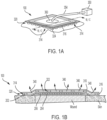
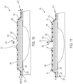
- a perimeter of the drape layer 202 extends beyond (e.g., circumscribes) a perimeter of the absorbent layer 204 (e.g., such as shown in FIG. 1B ), a perimeter of the manifold layer 208 (e.g., as shown in FIG. 1C ) and/or the perimeter of any other additional dressing layer(s) to provide an adhesive-coated margin for adhering the additional layers of the wound dressing 200 to the skin of a patient adjacent to the wound site being treated.
- the adhesive-coated margin can be eliminated and wound dressing 200 can be adhered to the skin of a patient using other techniques.
- the drape layer 202 may be formed from any number of different types of materials that are substantially impermeable to liquid and substantially permeable to moisture vapor. In other words, the drape layer 202 is permeable to water vapor, but not permeable to liquid water or wound exudate. This increases the total fluid handling capacity of the wound dressing 200 while promoting a moist wound environment. In some embodiments, the drape layer 202 is also impermeable to bacteria and other microorganisms.
- a suitable material for the drape layer 202 is a high moisture vapor transmission rate ("MVTR") material. As described in detail below, the wound treatment system 100 exploits the high MVTR of the drape layer 202 to manage fluids within the wound dressing 200.
- MVTR moisture vapor transmission rate
- the wound dressing 200 is an absorbent wound dressing comprising an absorbent layer 204 that is adapted to collect (e.g. store) fluid from the wound site.
- the size and shape of the absorbent layer 204 may be varied as desired.
- the absorbent layer 204 comprises superabsorbent particles held within a liquid-tight envelope (e.g. a woven or non-woven pouch).
- Other non-limiting examples of absorbent layer 204 materials include superabsorbent fibers, superabsorbent polymers, hydrofibers, sodium carboxymethyl cellulose, alginates, sodium polyacrylate, hydrogels, hydrocolloids, etc.
- the wound dressing 200 in various embodiments includes a manifold layer 208 configured to allow fluid (e.g. exudates, liquids, a vacuum created by the operation of the pump of the NPWT system) to be transmitted (e.g. distributed) to/from the wound.
- fluid e.g. exudates, liquids, a vacuum created by the operation of the pump of the NPWT system
- the manifold layer 208 may optionally include an open-cell foam marketed as GRANUFOAM TM by ACELITY TM .
- GRANUFOAM TM open-cell foam
- the interface layer 206 is configured to reduce potential adherence of the wound dressing 200 to the wound and/or to prevent ingrowth of skin to the wound dressing 200.
- the interface layer 206 may be defined by a nonporous material comprising a plurality of perforations (fenestrations, holes, airways, windows, slits, etc.) extending therethrough that allow air and fluid to pass between the wound and the other layers of the wound dressing 200.
- the interface layer 206 is made of a hydrophobic material such as polyethylene (PE) or other hydrophobic polymers.
- the interface layer 206 may comprise a liquid-impermeable, elastomeric film having a plurality of bi-directional, pressure-responsive perforations formed therethrough.
- the interface layer 206 is optionally dimensioned such that an outer perimeter of the interface layer 206 is coextensive with, or slightly greater than the manifold layer 208 and/or absorbent layer 204 (e.g., the area of the interface layer 206 is between approximately 5% and 10% greater than the area of the manifold layer 208 and/or absorbent layer 204).
- the fluid restrictions define elastic passages that can expand (e.g. open) in response to a pressure gradient to allow flow therethrough.
- the passages may be sufficiently small to form a seal or fluid restriction, thereby reducing or preventing liquid flow through the interface layer 206.
- various materials from which the film defining the interface layer 206 in such embodiments may be formed include polyurethane, polyethylene, acrylics, polyolefin (such as cyclic olefin copolymers), polyacetates, polyamides, polyesters, copolyesters, PEBAX block copolymers, thermoplastic elastomers, thermoplastic vulcanizates, polyethers, polyvinyl alcohols, polypropylene, polymethylpentene, polycarbonate, styreneics, silicones, fluoropolymers, acetates, etc.
- the film may have thickness between approximately 50 microns and approximately 250 microns, and more specifically between approximately 100 microns and approximately 200 microns.
- the perforations comprise linear slots having a length less than approximately 4 millimeters (e.g. 3 millimeters), with adjacent slots spaced approximately 3 millimeters from one another.
- the perforations may be defined by other configurations (e.g. holes) that are arranged in generally linear clusters having a length less than approximately 4 millimeters or less (e.g. 3 millimeters), with adjacent clusters optionally spaced approximately 3 millimeters from one another.
- the perforations may be defined by any other variety of arrangements and dimensions.
- the moisture management system 300 operates to control moisture levels in a treatment space defined underneath the wound dressing 200 of the wound treatment system 100 by forcing airflow along an upper, outer surface of the wound dressing 200.
- the management of moisture levels in the treatment space may, in some embodiments, optionally be supplemented via the direct removal of fluids from the treatment space using a source of forced negative airflow (e.g. a pump) fluidly coupled to the treatment space-the management of moisture levels using the moisture management system 300 of the wound treatment system 100 described herein does not itself require fluid communication with the treatment space beneath the wound dressing 200. Rather, the forced airflow along the wound dressing 200 generated during operation of the moisture management system 300 indirectly removes moisture from the treatment space (i.e. removes moisture from the treatment space even in the absence of any fluid communication with the treatment space) by accelerating the diffusion and evaporation of fluid within the treatment space through the high MVTR drape layer 202 of the wound dressing 200.
- the moisture management system 300 generally includes a film layer 310, a spacer structure 320, and an air displacement device 350.
- the film layer 310 and spacer structure 320 are configured to be coupled (e.g. attached, supported by, adhered, etc.) to the wound dressing 200 to define a flow path 340 that extends along an upper (e.g., exterior, outer, etc.) surface of the wound dressing 200 (i.e., along the upper surface 203 of the drape layer 202).
- the air displacement device 350 is configured to be fluidly coupled to the flow path 340, with operation of the air displacement device 350 being used to generate air flow across the upper surface 203 of the drape layer 202 of the wound dressing 200.
- the moisture management system 300 may be single use, or may optionally be configured to be re-used with different wound dressings 200.
- the moisture management system 300 is configured for stand-alone treatment of a wound (i.e., wherein the wound treatment system 100 operates independent of any other wound therapy system or device).
- the moisture management system 300 may be configured for use alongside other wound therapy systems, such as, e.g., an NPWT system.
- the film layer 310 (e.g. support layer) of the moisture management system 300 delimits an upper portion of a flow path 340 that extends along the upper surface 203 of the drape layer 202.
- an opening 312 extending through the film layer 310 fluidly couples the flow path 340 to the air displacement device 350.
- the opening 312 defines an inlet via which airflow generated by the air displacement device 350 enters the flow path 340.
- the opening 312 defines an outlet via which air is evacuated from the flow path 340 by the air displacement device 350.
- the film layer 310 optionally also includes and/or defines a plurality of vents 314 via which air flows into or out from the flow path 340 during operation of the air displacement device 350.
- the film layer 310 optionally supports a connector 360 (e.g., a port, a SENSAT.R.A.C. TM connection pad marketed by ACELITY TM , etc.) via which the air displacement device 350 is coupled to the flow path 340.
- the connector 360 may indirectly couple the air displacement device 350 to the flow path 340 via a conduit 354 that is attached to and extends between the connector 360 and a remotely located air displacement device 350.
- the air displacement device 350 and the connector 360 are components of an integrated module 400 (described in more detail below) that is supported relative to the film layer 310 (see, e.g., FIG. 9 ) around (e.g. adjacent to, surrounding, etc.) an outer periphery of the opening 312 in the film layer 310, such that the wound treatment system 100 defines a single, unitary structure.
- the opening 312 extends through a substantially central location of the film layer 310, so as to facilitate a generally uniform distribution of air flow along the upper surface of the wound dressing 200.
- the fluid opening 312 (and corresponding connection between the air displacement device 350 and the flow path 340) may be arranged at other locations relative to the film layer 310 and/or wound dressing 200.
- the opening 312 is optionally formed at a location along the film layer 310 that will overlie a region of the wound that exudes fluid at a high rate.
- the fluid opening 312 may be formed at a location adjacent to a lower perimeter of the film layer 310.
- the dimensions of the film layer 310 may be smaller, the same as, or larger than the dimensions of the wound dressing 200 of the wound treatment system 100.
- the dimensions of the film layer 310 relative to the wound dressing 200 may be selected based on an intended treatment protocol. For example, given the detrimental effect moisture may have on a periwound, in various embodiments the film layer 310 is sized to be coextensive with, or extend beyond, the outer perimeter of the wound dressing 200 to which the moisture management system 300 is attached, such as, e.g., representatively illustrated in FIGS 1A-1C .
- Such an arrangement advantageously allows the flow path 340 to be defined across the entirety of the upper surface 203 of the drape layer 202-including those portions of the drape layer 202 that overlay the periwound.
- the film layer 310 is dimensioned smaller than the wound dressing 200, such that a flow path 340 is defined along only a designated portion of the upper surface 203 of the drape layer 202.
- a flow path 340 is defined along only a designated portion of the upper surface 203 of the drape layer 202.
- the film layer 310 is attached to an underlying surface (e.g. an upper surface of the wound dressing 200, the skin of a patient, etc.) in situ during the attachment of the wound treatment system 100 to the patient.
- adhesive is optionally provided along portions, or the entirety, of the perimeter of the lower surface 311 of the film layer 310 to facilitate the attachment of the film layer 310 to the underlying surface.
- the film layer 310, spacer structure 320 and drape layer 202 are optionally provided as a single, integrated assembly, in which the perimeter of the film layer 310 is preattached (via, e.g., adhesive, welding, etc.) to the drape layer 202.
- the film layer 310 includes and/or defines one or more vents 314 via which air is forced out from or into the flow path 340 during operation of the air displacement device 350.
- the vents 314 include openings 315 (e.g. apertures, etc.) that extend through the film layer 310.
- the vents 314 may also optionally be defined by unattached portions 316 of a perimeter of the film layer 310 that are not directly coupled to an underlying surface (e.g. the wound dressing 200, the skin of a patient, etc.).
- an underlying surface e.g. the wound dressing 200, the skin of a patient, etc.
- the flow elements 322 of the spacer structure 320 (described below) that are located around (e.g.
- the perimeter of the film layer 310 are formed having a greater height (e.g., the flow elements 322 extend further downward relative to an upper surface 313 of the film layer 310) than flow elements 322 that are located along an interior portion of the lower surface 311 of the film layer 310.
- Such an increased height of the flow elements 322 located around the outer perimeter of the film layer 310 is configured to ensure that the unattached portions 316 of the outer periphery of the film layer 310 remain offset from the underlying surface to which the film layer 310 is attached (e.g. the wound dressing 200, the skin of the patient, etc.) and do not occlude flow into/out from the flow path 340.
- the spacer structure 320 and film layer 310 are optionally provided as a single, integral one-piece structure.
- the spacer structure 320 is monolithically formed with the film layer 310, with the flow elements 322 including structures that are defined by the lower surface 311 of the film layer 310.
- the flow elements 322 defining the spacer structure 320 include discrete structures that are attached to the lower surface 311 of the film layer 310.
- the flow elements 322 in some such embodiments include adhesive dots 324 (e.g. beads, islands, patches, etc.) formed from a cured semi-permanent or permanent adhesive (e.g., viscose UV curing adhesive).
- the adhesive dots 324 define discrete structures that are adhered at their respective first ends 321 to locations along the lower surface 311 of the film layer 310.
- the second ends 323 of the adhesive dots 324 adhere the film layer 310 relative to the upper surface 203 of the drape layer 202.
- the adhesive dots 324 are formed having a thickness (i.e.
- an adhesive composition may alternatively be applied to the lower surface 311 of the film layer 310 (and/or to the upper surface 203 of the drape layer 202) to form the adhesive dots 324 along the lower surface 311 of the film layer 310 and/or along the upper surface 203 of the drape layer 202 during assembly of the wound treatment system 100.
- the discrete and separate flow elements 322 that define a single, unitary spacer structure 320 and film layer 310 assembly may instead include one or more flow walls 328 that are attached (e.g. adhered) to the lower surface 311 of the film layer 310.
- the flow wall(s) 328 can be defined by a variety of different shapes, sizes, and configurations.
- FIG. 5 and 6 Exemplary embodiments of spacer structures 320 that are monolithically formed with the film layer 310 are shown in FIG. 5 and 6 .
- the lower surface 311 of the film layer 310 is textured, and includes a plurality of peaks 325 that are separated from one another by valleys 326.
- the flow elements 322 correspond to the peaks 325 of the textured surface, and are defined by portions of the lower surface 311 of the film layer 310 that extend further downward from an upper surface 313 of the film layer 310 (i.e. have an increased thickness) as compared to the portions of the lower surface 311 of the film layer 310 defining the valleys 326.
- the peaks 325 defining the flow elements 322 are shown as being truncated pyramids, the peaks 325 may be formed into a variety of other different shapes (e.g. ridges, ribs, posts, etc.).
- a lower surface 311 of the film layer 310 is embossed to define a plurality of raised portions 327 (i.e. non-embossed portions of the film layer 310).
- the flow elements 322 are defined by the raised portions 327 of the lower surface 311.
- the upper surface 313 of the film layer 310 may be debossed, and the flow elements 322 are defined by the downwardly projecting, debossed portions of the upper surface 313 of the film layer 310 (not shown).
- FIGS. 7 and 8 Shown in FIGS. 7 and 8 are exemplary embodiments of spacer structures 320 that are provided separately and discretely from the film layer 310, and which are arranged and optionally attached relative to the film layer 310 during assembly of the wound treatment system 100.
- the flow elements 322 include a plurality of struts 329 (e.g. walls) that are interconnected to form a scaffold which defines the spacer structure 320.
- the discretely and separately provided spacer structure 320 is defined by a porous layer 330.
- the porous layer 330 may be formed of a variety of different porous materials.
- the porous layer 330 optionally includes a felted foam (having, e.g., a thickness of between approximately 1cm and 3cm), or a non-felted foam (having, e.g., a thickness of less than approximately 5mm).
- the porous material from which the porous layer 330 is formed defines the flow element 322 of the spacer structure 320.
- the porous material e.g.
- the shape, size, and arrangement of flow elements 322 may be selected to define one or more enclosed flow channels that are discrete and fluidly isolated from other portions of the flow path 340 (such as, e.g., representatively illustrated by the embodiments of FIGS. 4 and 6 ).
- the arrangement of flow elements 322 in a non-uniform distribution, and/or the selection of flow elements 322 having varying sizes may be used to accelerate the rate of moisture removal at the target locations.
- the arrangement of flow elements 322 in a greater density and/or the arrangement of flow elements 322 having larger dimensioned second ends 323 at locations relative to portions of the wound dressing 200 that do not correspond to target locations minimizes the degree to which air flowing through the flow path 340 passes along the upper surface 203 of the drape layer 202 at such non-target locations. Resulting, less moisture is acquired by the air flowing through the flow path 340 prior to the air reaching a target location (e.g. a portion of the flow path 340 overlaying the periwound).
- drier air has a greater capacity to lift moisture from the upper surface 203 of the drape layer 202
- the decreased moisture level of the air flowing through the flow path 340 along the target locations increases the rate at which moisture may be removed from the target locations.
- a similar effect of delivering drier air flow to desired target locations may also be accomplished using an optional blocking structure (e.g. a thicker layer of adhesive, an intermediate layer of material, etc.) that is arranged between the spacer structure 320 and drape layer 202 along the portions of the wound dressing 200 that do not correspond to the target locations.
- an optional blocking structure e.g. a thicker layer of adhesive, an intermediate layer of material, etc.
- the air displacement device 350 may include any number of different air-moving devices (e.g., manual or automatic pump, blower, bellows, etc.). As shown in FIG. 1 , upon assembly of the wound treatment system 100, a remotely located air displacement device 350 is fluidly coupled to the flow path 340 via a conduit 354. Alternatively (as described in detail below), the air displacement device 350 is provided as a component of a module 400 that is supported by the film layer 310, such that the assembled wound treatment system 100 defines a single, self-contained device (see, e.g., FIG. 9 ).
- the air displacement device 350 is provided as a component of a module 400 that is supported by the film layer 310, such that the assembled wound treatment system 100 defines a single, self-contained device (see, e.g., FIG. 9 ).
- Operation of the air displacement device 350 is configured to generate a flow of air through the flow path 340 of the wound treatment system 100.
- operation of the air displacement device 350 in a positive pressure mode causes air to flow from the air displacement device 350, through the opening 312 in the film layer 3 10, through the flow path 340 defined by the flow elements 322 of the spacer structure 320, through one or more vents 314, and into the ambient environment.
- operation of the air displacement device 350 in a negative pressure mode generates a vacuum that evacuates air through the opening 312 in the film layer 310 that has been drawn into the flow path 340 via the vents 314.
- the air displacement device 350 forces air into (or out from) the flow path 340 at a rate of between approximately 0.5L/min and approximately 2L/min, which creates a backpressure of approximately 10mmHg.
- the air displacement device 350 may be provided in addition to the pump of the additional wound treatment system (e.g., a NPWT system), such that such that the wound treatment system 100 is capable of being operated independently and separately from the NPWT system (or other wound treatment system).
- the additional wound treatment system e.g., a NPWT system
- the connector 360 optionally includes one or more valves via which the shared pump is selectively fluidly coupled to either the NPWT conduit 361 or the moisture management conduit 363 based on the desired treatment.
- the connector 360 includes an optional proportional leak valve configured to fluidly couple the pump to moisture management conduit 363 while fluidly isolating the NPWT conduit 361 during operation of the shared pump to generate pressures in excess of a predetermined threshold (e.g. at negative pressures above 150mmHg).
- a predetermined threshold e.g. at negative pressures above 150mmHg.
- the valve is configured to fluidly couple the pump to the NPWT conduit 361, while fluidly isolating the moisture management conduit 363.
- the shared pump that defines the air displacement device 350 is operated to simultaneously provide treatment using each treatment system.
- the wound treatment system 100 is operated in a negative pressure mode concurrently with the operation of the pump to provide NPWT treatment.
- an optional valve of the connector 360 is selectively actuated such that each of the NPWT conduit 361 and moisture management conduit 363 are fluidly coupled to the pump.
- the wound treatment system 100 can also be operated in the positive pressure mode concurrently with the operation of the pump to provide NPWT treatment.
- an outlet of the pump is coupled (e.g. via a valve) to the moisture management conduit 363, with that exhaust airflow resulting from the operation of the pump to generate a vacuum for the NPWT treatment being used as the positive forced airflow that is delivered to the flow path 340 via the moisture management conduit 363.
- an optional valve is selectively actuated to restrict (e.g. reduce the diameter of) a portion of the NPWT conduit 361 located upstream of a Venturi tube (or a selectively openable passageway) that fluidly couples the NPWT conduit 361 and moisture management conduit 363. The decrease in pressure resulting from air flow through the restriction in the NPWT conduit 361 causes positive forced airflow to be directed through the Venturi tube (or passageway) and into the flow path 340.
- the wound treatment system 100 may optionally be formed as an integral self-contained system that may be supported entirely by a patient.
- the air displacement device 350, as well as any additional optional components of the wound treatment system 100 are housed in an optional module 400.
- the module 400 may optionally also support a patient interface comprising a display and/or user inputs (e.g., buttons) via which information may be provided to and/or received from a user during operation of the wound treatment system 100.
- the module 400 may also contain a reservoir (e.g., an absorbent material, a canister, etc.) configured to store fluid that has been evaporated from the wound dressing 200 and/or that is evacuated from the treatment space defined underneath the wound dressing 200 and/or any other number of components of the additional wound therapy system.
- a reservoir e.g., an absorbent material, a canister, etc.
- the module 400 optionally includes an engagement structure configured allow the module 400 to be sealingly secured around (e.g. adjacent to, surrounding, etc.) an outer periphery of the opening 312 in the film layer 310 via an engagement to an optional connector 360 supported relative to the film layer 310.
- the module 400 may also be secured directly to the film layer 310 using adhesive, welding, etc.
- bacterial and/or hydrophobic filters 380 are optionally provided between the opening 312 in the film layer 310 and an inlet of the module 400.
- filters 380 may be attached to any one or more of the opening 312 in the film layer 310, the connector 360, and the engagement structure of the module 400 to prevent fluid and/or bacterial ingress and contamination of the module 400 during use of the wound treatment system 100 and/or during attachment or removal of the module 400 to or from wound dressing 200.
- Various operations of the wound treatment system 100 may be controlled by an optional controller 500 (shown, e.g., in FIG. 9 ).
- the controller 500 may turn the air displacement device 350 on/off, and/or can be used to vary the speed at which the air displacement device 350 is operated.
- the controller 500 may also provide selective control over the actuation of any optional valves of the connector 360 during operation of the wound treatment system 100 (e.g. to switch operation of the air displacement device 350 between positive and negative pressure modes, to switch between the type of treatment being provided during operation of the wound treatment system 100 in conjunction with an additional wound therapy system, etc.).
- the controller 500 may be configured to operate the various components of the wound treatment system 100 (e.g. the air displacement device 350, valves, etc.) based on a variety of different inputs received from any number of different sources. For example, in some embodiments, the controller 500 may operate the wound treatment system 100 based on inputs received from a user. In other embodiments, the controller 500 may be configured to operate the wound treatment system 100 in accordance to one or more preprogrammed modes stored in a memory of the controller 500. For example, the controller 500 may operate the wound treatment system 100 in an alternating pressure mode, in which operation of the air displacement device 350 is periodically varied between operation in the positive pressure mode, and operation in the negative pressure mode. Such periodic alternation between positive and negative air flow may advantageously be used disrupt regions of dense flow within the treatment space underneath the wound dressing 200 and to allow moisture to be removed more uniformly from the wound.
- the controller 500 may operate the various components of the wound treatment system 100 (e.g. the air displacement device 350, valves, etc.) based on a variety of different input
- the controller 500 is configured to operate the wound treatment system 100 responsive to readings or measurement obtained from one or more sensors (e.g. moisture sensor, humidity sensor, pressure sensor, etc.) incorporated into the wound treatment system 100.
- the wound treatment system 100 includes a moisture level sensor assembly comprising one or more moisture indicators and an optical reader configured to detect changes in the indicators.
- the indicators are advantageously selected to be capable of providing a dynamic, two-way (i.e. reversible), near real-time indication as to both increases and decreases in moisture levels within the wound dressing 200 over the course of use of the wound treatment system 100.
- Such an incorporation of indicators into the wound treatment system 100 allows the wound dressing 200 to remain integral and sealed, and thus advantageously minimizes the risk of exudates, or other fluids or substances from the treatment space underneath the wound dressing 200, contaminating the components of the optionally included module 400.
- the moisture indicators are incorporated into (i.e. positioned in direct contact with) one or both of the drape layer 202 and an additional dressing layer (e.g., an absorbent layer 204, a manifold layer 208, etc.), so as to be capable of dynamically responding to changes in moisture levels within the wound dressing 200 (e.g. changes in the fluid capacity of the absorbent layer 204, moisture levels at a portions of the drape layer 202 overlaying the periwound, etc.).
- the indicators are advantageously positioned directly below the drape layer 202 to facilitate the ability of the optical reader to detect changes in the visual appearance of the indicators through the drape layer 202.
- a fusible fiber optionally secures the indicators relative to the wound dressing 200 to ensure contact of the indicators with the absorbent layer 204 and/or to ensure that the indicators are aligned relative to the module 400 such that visual transformations of the indicators are capable of being detected by the optical reader.
- the optical reader is optionally incorporated into the module 400, or is otherwise positionable relative to the upper surface of the wound treatment system 100.
- the controller 500 is optionally configured to operate the air displacement device 350 in a manner configured to minimize power consumption.
- the controller 500 may optionally be configured to initiate operation of the air displacement 350 to generate airflow through the flow path 340 only in response to the detection of a visual transition of an indicator indicative of the moisture level in the treatment space underneath the wound dressing 200 being equal to, or exceeding, a predetermined upper threshold moisture level.
- the controller 500 may optionally be configured to initiate operation of the air displacement 350 to generate airflow through the flow path 340 in response to the detection of a visual transition of an indicator indicative of the moisture level at the periwound being equal to, or exceeding, a predetermined upper threshold moisture level.
- the controller 500 Upon detecting (e.g. via a visual transition of the indicators) that the moisture level has decreased to a level equal to or below an intermediate moisture level, the controller 500 is optionally configured to reduce the speed at which the air displacement device 350 is operated.
- a predetermined lower threshold e.g. between approximately 40% and less than approximately 50% of the fluid capacity of the wound dressing 200
- the controller 500 ceases operation of the air displacement device 350 to save power until such a time when the moisture level in the treatment space (e.g. a moisture level of an optional absorbent layer 204, a moisture level at the periwound, etc.) is detected to again be equal to or greater than the upper predetermined threshold.
- Such selective operation of the air displacement device 350 may continue one or more times during the operation of the wound treatment system 100.
- the controller 500 may be configured to continuously receive readings and measurements from one or more sensors (e.g., from a moisture level sensor assembly). Alternatively-to further conserve power-the controller 500 may instead be configured to selectively obtain sensor readings only at predetermined intervals (e.g., every 3-5 minutes). In some such embodiments, the predetermined interval at which the sensor readings are obtained may vary in response to the detection of various threshold sensor readings. For example, the controller 500 may be configured to obtain moisture level readings at a more frequent interval following the detection (using, e.g., the moisture level sensor assembly) that a moisture level underneath the wound dressing 200 is equal to, or exceeds, an upper moisture level threshold.
- the air displacement device 350 optionally comprises a plurality of independently operable air displacement devices 350 that are fluidly coupled at various locations to the flow path 340 around (e.g. adjacent to, surrounding, etc.) the outer peripheries of various openings 312 in the film layer 310.
- the operation of some or all of the air displacement devices 350 is optionally independently controllable, allowing moisture levels to be managed as needed at specific target areas along the wound dressing 200.
- each individual air displacement device 350 is individually controllable responsive to a moisture level reading (or other sensed condition) obtained from a moisture indicator (or other sensor) positioned at a location relative to the wound that corresponds to the location at which the respective air displacement device 350 is positioned.
- a moisture level reading or other sensed condition
- a moisture indicator or other sensor
Landscapes
- Health & Medical Sciences (AREA)
- Life Sciences & Earth Sciences (AREA)
- Engineering & Computer Science (AREA)
- Biomedical Technology (AREA)
- Heart & Thoracic Surgery (AREA)
- Vascular Medicine (AREA)
- Animal Behavior & Ethology (AREA)
- General Health & Medical Sciences (AREA)
- Public Health (AREA)
- Veterinary Medicine (AREA)
- Dermatology (AREA)
- Media Introduction/Drainage Providing Device (AREA)
- Surgical Instruments (AREA)
- Materials For Medical Uses (AREA)
Claims (11)
- Système de traitement de plaie (100), comprenant :
un pansement pour plaie (200) comprenant une couche de champ (202) et un système de gestion d'humidité (300) comprenant :une couche de film (310) ;un ensemble d'espacement comprenant :un ou plusieurs éléments d'écoulement (322) ayant chacun une surface externe qui s'étend entre une première extrémité (321) et une seconde extrémité (323), les premières extrémités étant localisées adjacentes à, et s'étendent vers le bas par rapport à, une surface inférieure (311) de la couche de film (310), et les secondes extrémités (323) étant localisées adjacentes à, et s'étendant vers le haut par rapport à, la surface supérieure (203) de la couche de champ (202) ;l'ensemble d'espacement définissant un espace entre la surface inférieure (311) de la couche de film (310) et la surface supérieure (203) de la couche de champ (202) définissant un trajet d'écoulement (340) entre les surfaces supérieure et inférieure (203, 311) et le ou les éléments d'écoulement (322)
etun dispositif de déplacement d'air (350) en prise étanche avec une ouverture (312) formée dans, et s'étendant à travers, la couche de film (310) et configuré pour amener de l'air à s'écouler à travers le trajet d'écoulement (340) ;dans lequel l'ensemble d'espacement et la couche de film (310) définissent une structure monolithique ;dans lequel la surface inférieure (311) de la couche de film (310) est en relief pour définir le ou les éléments d'écoulement (322) en guise de parties surélevées (327) de la surface inférieure (311), et/ou la surface supérieure (313) de la couche de film (310) est en creux pour définir le ou les éléments d'écoulement (322) en guise de parties en creux, faisant saillie vers le bas, de la surface supérieure (313) de la couche de film (310). - Système de traitement de plaie (100) selon la revendication 1, dans lequel le dispositif de déplacement d'air (350) est entièrement supporté au-dessus d'une surface supérieure de la couche de film (310).
- Système de traitement de plaie (100) selon la revendication 1, dans lequel le dispositif de déplacement d'air (350) comprend une structure de raccord attachée de manière étanche autour de l'ouverture dans la couche de film (310), la structure de raccord étant raccordée fluidiquement à une pompe localisée à distance de la couche de film (310) par un conduit.
- Système de traitement de plaie (100) selon la revendication 1, dans lequel le pansement pour plaie (200) comporte en outre une couche absorbante conçue pour stocker un fluide exsudant d'une plaie.
- Système de traitement de plaie (100) selon la revendication 1, dans lequel la couche absorbante (204) comprend un matériau superabsorbant.
- Système de traitement de plaie (100) selon la revendication 5, dans lequel le matériau superabsorbant est contenu au sein d'une poche formée d'un matériau non tissé.
- Système de traitement de plaie (100) selon la revendication 1, dans lequel le pansement pour plaie (200) comporte en outre une couche de collecteur (208) conçue pour permettre à un fluide d'être transmis à la plaie.
- Système de traitement de plaie (100) selon la revendication 7, dans lequel la couche de collecteur (208) comprend une mousse à alvéoles ouvertes.
- Système de traitement de plaie (100) selon la revendication 1, dans lequel le pansement pour plaie (200) comporte en outre une couche non poreuse d'interface de plaie (206).
- Système de traitement de plaie (100) selon la revendication 9, dans lequel l'interface de plaie (206) comprend un film de polyuréthane.
- Système de traitement de plaie (100) selon la revendication 9, dans lequel le film comporte une pluralité de perforations s'étendant à travers celui-ci.
Applications Claiming Priority (2)
| Application Number | Priority Date | Filing Date | Title |
|---|---|---|---|
| US201962890316P | 2019-08-22 | 2019-08-22 | |
| PCT/IB2020/057196 WO2021033052A1 (fr) | 2019-08-22 | 2020-07-30 | Système et méthode de gestion d'humidité de pansement à l'aide d'un flux d'air forcé |
Publications (2)
| Publication Number | Publication Date |
|---|---|
| EP4017445A1 EP4017445A1 (fr) | 2022-06-29 |
| EP4017445B1 true EP4017445B1 (fr) | 2025-02-26 |
Family
ID=71948648
Family Applications (1)
| Application Number | Title | Priority Date | Filing Date |
|---|---|---|---|
| EP20751309.4A Active EP4017445B1 (fr) | 2019-08-22 | 2020-07-30 | Système de gestion d'humidité de pansement à l'aide d'un flux d'air forcé |
Country Status (3)
| Country | Link |
|---|---|
| US (1) | US20220339041A1 (fr) |
| EP (1) | EP4017445B1 (fr) |
| WO (1) | WO2021033052A1 (fr) |
Families Citing this family (5)
| Publication number | Priority date | Publication date | Assignee | Title |
|---|---|---|---|---|
| GB201914725D0 (en) | 2019-10-11 | 2019-11-27 | Smith & Nephew | Apparatuses and methods for negative pressure wound therapy |
| GB201914706D0 (en) | 2019-10-11 | 2019-11-27 | Smith & Nephew | Apparatuses and methods for negative pressure wound therapy with switcheable fluid management |
| GB202006305D0 (en) | 2020-04-29 | 2020-06-10 | Smith & Nephew | Apparatures and methods for negative pressure wound therapy |
| TWI740755B (zh) * | 2020-12-24 | 2021-09-21 | 南緯實業股份有限公司 | 敷料 |
| GB202414412D0 (en) * | 2024-10-01 | 2024-11-13 | Smith & Nephew | Negative pressure therapy systems, devices, and methods |
Citations (1)
| Publication number | Priority date | Publication date | Assignee | Title |
|---|---|---|---|---|
| US20180214315A1 (en) * | 2017-01-27 | 2018-08-02 | Kci Licensing, Inc. | Multi-Layer Abdominal Closure Dressing With Instillation Capabilities |
Family Cites Families (8)
| Publication number | Priority date | Publication date | Assignee | Title |
|---|---|---|---|---|
| GB1280631A (en) | 1968-07-09 | 1972-07-05 | Smith & Nephew | Adhesive materials |
| DE202004017052U1 (de) * | 2004-11-02 | 2005-06-09 | Riesinger, Birgit | Vorrichtung zur Wundbehandlung unter Einsatz von Unterdruck |
| ES2776709T3 (es) * | 2007-11-21 | 2020-07-31 | Smith & Nephew | Apósito para heridas |
| WO2011104388A1 (fr) * | 2010-02-26 | 2011-09-01 | Vir I Kinda Ab | Pansement pour plaies comportant une substance super absorbante |
| JP2014514089A (ja) * | 2011-04-12 | 2014-06-19 | ケーシーアイ ライセンシング インコーポレイテッド | 蒸発装置を備える減圧ドレッシング、システム、および方法 |
| CA3065521A1 (fr) * | 2017-06-07 | 2018-12-13 | Kci Licensing, Inc. | Pansement pour cavite de plaie multicouche pour duree d'utilisation prolongee |
| AU2018293064A1 (en) * | 2017-06-30 | 2019-12-05 | T.J.Smith & Nephew,Limited | Spacer layer for use in a wound dressing |
| US11850122B2 (en) * | 2017-11-02 | 2023-12-26 | 3M Innovative Properties Company | Wound dressing with humidity colorimeter sensor |
-
2020
- 2020-07-30 EP EP20751309.4A patent/EP4017445B1/fr active Active
- 2020-07-30 US US17/637,237 patent/US20220339041A1/en not_active Abandoned
- 2020-07-30 WO PCT/IB2020/057196 patent/WO2021033052A1/fr not_active Ceased
Patent Citations (1)
| Publication number | Priority date | Publication date | Assignee | Title |
|---|---|---|---|---|
| US20180214315A1 (en) * | 2017-01-27 | 2018-08-02 | Kci Licensing, Inc. | Multi-Layer Abdominal Closure Dressing With Instillation Capabilities |
Also Published As
| Publication number | Publication date |
|---|---|
| US20220339041A1 (en) | 2022-10-27 |
| WO2021033052A1 (fr) | 2021-02-25 |
| EP4017445A1 (fr) | 2022-06-29 |
Similar Documents
| Publication | Publication Date | Title |
|---|---|---|
| EP4017445B1 (fr) | Système de gestion d'humidité de pansement à l'aide d'un flux d'air forcé | |
| US12127919B2 (en) | Negative pressure wound treatment apparatuses and methods with integrated electronics | |
| US12097094B2 (en) | Dressing and method for applying reduced pressure to and collecting and storing fluid from a tissue site | |
| WO2021033051A1 (fr) | Pansement pour extrémité pour la gestion d'humidité à écoulement d'air forcé | |
| WO2022034410A1 (fr) | Pansement pour thérapie par pression négative avec fenêtre d'observation | |
| AU2014277788B2 (en) | Dressing and method for applying reduced pressure to and collecting and storing fluid from a tissue site |
Legal Events
| Date | Code | Title | Description |
|---|---|---|---|
| STAA | Information on the status of an ep patent application or granted ep patent |
Free format text: STATUS: UNKNOWN |
|
| STAA | Information on the status of an ep patent application or granted ep patent |
Free format text: STATUS: THE INTERNATIONAL PUBLICATION HAS BEEN MADE |
|
| PUAI | Public reference made under article 153(3) epc to a published international application that has entered the european phase |
Free format text: ORIGINAL CODE: 0009012 |
|
| STAA | Information on the status of an ep patent application or granted ep patent |
Free format text: STATUS: REQUEST FOR EXAMINATION WAS MADE |
|
| 17P | Request for examination filed |
Effective date: 20220321 |
|
| AK | Designated contracting states |
Kind code of ref document: A1 Designated state(s): AL AT BE BG CH CY CZ DE DK EE ES FI FR GB GR HR HU IE IS IT LI LT LU LV MC MK MT NL NO PL PT RO RS SE SI SK SM TR |
|
| DAV | Request for validation of the european patent (deleted) | ||
| DAX | Request for extension of the european patent (deleted) | ||
| STAA | Information on the status of an ep patent application or granted ep patent |
Free format text: STATUS: EXAMINATION IS IN PROGRESS |
|
| 17Q | First examination report despatched |
Effective date: 20230810 |
|
| RAP1 | Party data changed (applicant data changed or rights of an application transferred) |
Owner name: 3M INNOVATIVE PROPERTIES COMPANY |
|
| RAP1 | Party data changed (applicant data changed or rights of an application transferred) |
Owner name: SOLVENTUM INTELLECTUAL PROPERTIES COMPANY |
|
| REG | Reference to a national code |
Ref country code: DE Ipc: A61F0013020300 Ref legal event code: R079 Ref document number: 602020046774 Country of ref document: DE Free format text: PREVIOUS MAIN CLASS: A61F0013020000 |
|
| GRAP | Despatch of communication of intention to grant a patent |
Free format text: ORIGINAL CODE: EPIDOSNIGR1 |
|
| STAA | Information on the status of an ep patent application or granted ep patent |
Free format text: STATUS: GRANT OF PATENT IS INTENDED |
|
| GRAJ | Information related to disapproval of communication of intention to grant by the applicant or resumption of examination proceedings by the epo deleted |
Free format text: ORIGINAL CODE: EPIDOSDIGR1 |
|
| STAA | Information on the status of an ep patent application or granted ep patent |
Free format text: STATUS: EXAMINATION IS IN PROGRESS |
|
| GRAP | Despatch of communication of intention to grant a patent |
Free format text: ORIGINAL CODE: EPIDOSNIGR1 |
|
| STAA | Information on the status of an ep patent application or granted ep patent |
Free format text: STATUS: GRANT OF PATENT IS INTENDED |
|
| GRAJ | Information related to disapproval of communication of intention to grant by the applicant or resumption of examination proceedings by the epo deleted |
Free format text: ORIGINAL CODE: EPIDOSDIGR1 |
|
| STAA | Information on the status of an ep patent application or granted ep patent |
Free format text: STATUS: EXAMINATION IS IN PROGRESS |
|
| RIC1 | Information provided on ipc code assigned before grant |
Ipc: A61F 13/05 20240101ALI20240919BHEP Ipc: A61F 13/0203 20240101AFI20240919BHEP |
|
| GRAP | Despatch of communication of intention to grant a patent |
Free format text: ORIGINAL CODE: EPIDOSNIGR1 |
|
| STAA | Information on the status of an ep patent application or granted ep patent |
Free format text: STATUS: GRANT OF PATENT IS INTENDED |
|
| INTG | Intention to grant announced |
Effective date: 20240930 |
|
| INTG | Intention to grant announced |
Effective date: 20241008 |
|
| INTC | Intention to grant announced (deleted) | ||
| INTG | Intention to grant announced |
Effective date: 20241028 |
|
| GRAS | Grant fee paid |
Free format text: ORIGINAL CODE: EPIDOSNIGR3 |
|
| GRAA | (expected) grant |
Free format text: ORIGINAL CODE: 0009210 |
|
| STAA | Information on the status of an ep patent application or granted ep patent |
Free format text: STATUS: THE PATENT HAS BEEN GRANTED |
|
| AK | Designated contracting states |
Kind code of ref document: B1 Designated state(s): AL AT BE BG CH CY CZ DE DK EE ES FI FR GB GR HR HU IE IS IT LI LT LU LV MC MK MT NL NO PL PT RO RS SE SI SK SM TR |
|
| REG | Reference to a national code |
Ref country code: GB Ref legal event code: FG4D |
|
| REG | Reference to a national code |
Ref country code: CH Ref legal event code: EP |
|
| REG | Reference to a national code |
Ref country code: DE Ref legal event code: R096 Ref document number: 602020046774 Country of ref document: DE |
|
| REG | Reference to a national code |
Ref country code: IE Ref legal event code: FG4D |
|
| REG | Reference to a national code |
Ref country code: NL Ref legal event code: MP Effective date: 20250226 |
|
| PG25 | Lapsed in a contracting state [announced via postgrant information from national office to epo] |
Ref country code: RS Free format text: LAPSE BECAUSE OF FAILURE TO SUBMIT A TRANSLATION OF THE DESCRIPTION OR TO PAY THE FEE WITHIN THE PRESCRIBED TIME-LIMIT Effective date: 20250526 |
|
| PG25 | Lapsed in a contracting state [announced via postgrant information from national office to epo] |
Ref country code: FI Free format text: LAPSE BECAUSE OF FAILURE TO SUBMIT A TRANSLATION OF THE DESCRIPTION OR TO PAY THE FEE WITHIN THE PRESCRIBED TIME-LIMIT Effective date: 20250226 |
|
| PG25 | Lapsed in a contracting state [announced via postgrant information from national office to epo] |
Ref country code: PL Free format text: LAPSE BECAUSE OF FAILURE TO SUBMIT A TRANSLATION OF THE DESCRIPTION OR TO PAY THE FEE WITHIN THE PRESCRIBED TIME-LIMIT Effective date: 20250226 |
|
| PG25 | Lapsed in a contracting state [announced via postgrant information from national office to epo] |
Ref country code: ES Free format text: LAPSE BECAUSE OF FAILURE TO SUBMIT A TRANSLATION OF THE DESCRIPTION OR TO PAY THE FEE WITHIN THE PRESCRIBED TIME-LIMIT Effective date: 20250226 |
|
| PGFP | Annual fee paid to national office [announced via postgrant information from national office to epo] |
Ref country code: GB Payment date: 20250619 Year of fee payment: 6 |
|
| REG | Reference to a national code |
Ref country code: LT Ref legal event code: MG9D |
|
| PG25 | Lapsed in a contracting state [announced via postgrant information from national office to epo] |
Ref country code: IS Free format text: LAPSE BECAUSE OF FAILURE TO SUBMIT A TRANSLATION OF THE DESCRIPTION OR TO PAY THE FEE WITHIN THE PRESCRIBED TIME-LIMIT Effective date: 20250626 Ref country code: NO Free format text: LAPSE BECAUSE OF FAILURE TO SUBMIT A TRANSLATION OF THE DESCRIPTION OR TO PAY THE FEE WITHIN THE PRESCRIBED TIME-LIMIT Effective date: 20250526 |
|
| PG25 | Lapsed in a contracting state [announced via postgrant information from national office to epo] |
Ref country code: NL Free format text: LAPSE BECAUSE OF FAILURE TO SUBMIT A TRANSLATION OF THE DESCRIPTION OR TO PAY THE FEE WITHIN THE PRESCRIBED TIME-LIMIT Effective date: 20250226 |
|
| PG25 | Lapsed in a contracting state [announced via postgrant information from national office to epo] |
Ref country code: HR Free format text: LAPSE BECAUSE OF FAILURE TO SUBMIT A TRANSLATION OF THE DESCRIPTION OR TO PAY THE FEE WITHIN THE PRESCRIBED TIME-LIMIT Effective date: 20250226 |
|
| PG25 | Lapsed in a contracting state [announced via postgrant information from national office to epo] |
Ref country code: PT Free format text: LAPSE BECAUSE OF FAILURE TO SUBMIT A TRANSLATION OF THE DESCRIPTION OR TO PAY THE FEE WITHIN THE PRESCRIBED TIME-LIMIT Effective date: 20250626 Ref country code: LV Free format text: LAPSE BECAUSE OF FAILURE TO SUBMIT A TRANSLATION OF THE DESCRIPTION OR TO PAY THE FEE WITHIN THE PRESCRIBED TIME-LIMIT Effective date: 20250226 |
|
| PG25 | Lapsed in a contracting state [announced via postgrant information from national office to epo] |
Ref country code: BG Free format text: LAPSE BECAUSE OF FAILURE TO SUBMIT A TRANSLATION OF THE DESCRIPTION OR TO PAY THE FEE WITHIN THE PRESCRIBED TIME-LIMIT Effective date: 20250226 Ref country code: GR Free format text: LAPSE BECAUSE OF FAILURE TO SUBMIT A TRANSLATION OF THE DESCRIPTION OR TO PAY THE FEE WITHIN THE PRESCRIBED TIME-LIMIT Effective date: 20250527 |
|
| REG | Reference to a national code |
Ref country code: AT Ref legal event code: MK05 Ref document number: 1769939 Country of ref document: AT Kind code of ref document: T Effective date: 20250226 |
|
| PG25 | Lapsed in a contracting state [announced via postgrant information from national office to epo] |
Ref country code: SE Free format text: LAPSE BECAUSE OF FAILURE TO SUBMIT A TRANSLATION OF THE DESCRIPTION OR TO PAY THE FEE WITHIN THE PRESCRIBED TIME-LIMIT Effective date: 20250226 |
|
| PG25 | Lapsed in a contracting state [announced via postgrant information from national office to epo] |
Ref country code: SM Free format text: LAPSE BECAUSE OF FAILURE TO SUBMIT A TRANSLATION OF THE DESCRIPTION OR TO PAY THE FEE WITHIN THE PRESCRIBED TIME-LIMIT Effective date: 20250226 |
|
| PG25 | Lapsed in a contracting state [announced via postgrant information from national office to epo] |
Ref country code: DK Free format text: LAPSE BECAUSE OF FAILURE TO SUBMIT A TRANSLATION OF THE DESCRIPTION OR TO PAY THE FEE WITHIN THE PRESCRIBED TIME-LIMIT Effective date: 20250226 |
|
| PGFP | Annual fee paid to national office [announced via postgrant information from national office to epo] |
Ref country code: DE Payment date: 20250620 Year of fee payment: 6 |
|
| PG25 | Lapsed in a contracting state [announced via postgrant information from national office to epo] |
Ref country code: IT Free format text: LAPSE BECAUSE OF FAILURE TO SUBMIT A TRANSLATION OF THE DESCRIPTION OR TO PAY THE FEE WITHIN THE PRESCRIBED TIME-LIMIT Effective date: 20250226 |
|
| PG25 | Lapsed in a contracting state [announced via postgrant information from national office to epo] |
Ref country code: AT Free format text: LAPSE BECAUSE OF FAILURE TO SUBMIT A TRANSLATION OF THE DESCRIPTION OR TO PAY THE FEE WITHIN THE PRESCRIBED TIME-LIMIT Effective date: 20250226 |
|
| PG25 | Lapsed in a contracting state [announced via postgrant information from national office to epo] |
Ref country code: EE Free format text: LAPSE BECAUSE OF FAILURE TO SUBMIT A TRANSLATION OF THE DESCRIPTION OR TO PAY THE FEE WITHIN THE PRESCRIBED TIME-LIMIT Effective date: 20250226 Ref country code: CZ Free format text: LAPSE BECAUSE OF FAILURE TO SUBMIT A TRANSLATION OF THE DESCRIPTION OR TO PAY THE FEE WITHIN THE PRESCRIBED TIME-LIMIT Effective date: 20250226 |
|
| PG25 | Lapsed in a contracting state [announced via postgrant information from national office to epo] |
Ref country code: RO Free format text: LAPSE BECAUSE OF FAILURE TO SUBMIT A TRANSLATION OF THE DESCRIPTION OR TO PAY THE FEE WITHIN THE PRESCRIBED TIME-LIMIT Effective date: 20250226 |
|
| PG25 | Lapsed in a contracting state [announced via postgrant information from national office to epo] |
Ref country code: SK Free format text: LAPSE BECAUSE OF FAILURE TO SUBMIT A TRANSLATION OF THE DESCRIPTION OR TO PAY THE FEE WITHIN THE PRESCRIBED TIME-LIMIT Effective date: 20250226 |
|
| REG | Reference to a national code |
Ref country code: DE Ref legal event code: R097 Ref document number: 602020046774 Country of ref document: DE |
|
| PLBE | No opposition filed within time limit |
Free format text: ORIGINAL CODE: 0009261 |
|
| STAA | Information on the status of an ep patent application or granted ep patent |
Free format text: STATUS: NO OPPOSITION FILED WITHIN TIME LIMIT |
|
| REG | Reference to a national code |
Ref country code: CH Ref legal event code: L10 Free format text: ST27 STATUS EVENT CODE: U-0-0-L10-L00 (AS PROVIDED BY THE NATIONAL OFFICE) Effective date: 20260107 |
|
| 26N | No opposition filed |
Effective date: 20251127 |
|
| REG | Reference to a national code |
Ref country code: CH Ref legal event code: H13 Free format text: ST27 STATUS EVENT CODE: U-0-0-H10-H13 (AS PROVIDED BY THE NATIONAL OFFICE) Effective date: 20260224 |
|
| PG25 | Lapsed in a contracting state [announced via postgrant information from national office to epo] |
Ref country code: LU Free format text: LAPSE BECAUSE OF NON-PAYMENT OF DUE FEES Effective date: 20250730 |
|
| REG | Reference to a national code |
Ref country code: BE Ref legal event code: MM Effective date: 20250731 |
|
| PG25 | Lapsed in a contracting state [announced via postgrant information from national office to epo] |
Ref country code: BE Free format text: LAPSE BECAUSE OF NON-PAYMENT OF DUE FEES Effective date: 20250731 |
|
| PG25 | Lapsed in a contracting state [announced via postgrant information from national office to epo] |
Ref country code: FR Free format text: LAPSE BECAUSE OF NON-PAYMENT OF DUE FEES Effective date: 20250731 |
|
| PG25 | Lapsed in a contracting state [announced via postgrant information from national office to epo] |
Ref country code: CH Free format text: LAPSE BECAUSE OF NON-PAYMENT OF DUE FEES Effective date: 20250731 |