EP4018040B1 - Materialtransferfahrzeug mit bodenbedienstation - Google Patents
Materialtransferfahrzeug mit bodenbedienstation Download PDFInfo
- Publication number
- EP4018040B1 EP4018040B1 EP20857737.9A EP20857737A EP4018040B1 EP 4018040 B1 EP4018040 B1 EP 4018040B1 EP 20857737 A EP20857737 A EP 20857737A EP 4018040 B1 EP4018040 B1 EP 4018040B1
- Authority
- EP
- European Patent Office
- Prior art keywords
- ground operator
- transfer vehicle
- material transfer
- loading conveyor
- receiving device
- Prior art date
- Legal status (The legal status is an assumption and is not a legal conclusion. Google has not performed a legal analysis and makes no representation as to the accuracy of the status listed.)
- Active
Links
Images


Classifications
-
- E—FIXED CONSTRUCTIONS
- E01—CONSTRUCTION OF ROADS, RAILWAYS, OR BRIDGES
- E01C—CONSTRUCTION OF, OR SURFACES FOR, ROADS, SPORTS GROUNDS, OR THE LIKE; MACHINES OR AUXILIARY TOOLS FOR CONSTRUCTION OR REPAIR
- E01C19/00—Machines, tools or auxiliary devices for preparing or distributing paving materials, for working the placed materials, or for forming, consolidating, or finishing the paving
- E01C19/48—Machines, tools or auxiliary devices for preparing or distributing paving materials, for working the placed materials, or for forming, consolidating, or finishing the paving for laying-down the materials and consolidating them, or finishing the surface, e.g. slip forms therefor, forming kerbs or gutters in a continuous operation in situ
-
- E—FIXED CONSTRUCTIONS
- E01—CONSTRUCTION OF ROADS, RAILWAYS, OR BRIDGES
- E01C—CONSTRUCTION OF, OR SURFACES FOR, ROADS, SPORTS GROUNDS, OR THE LIKE; MACHINES OR AUXILIARY TOOLS FOR CONSTRUCTION OR REPAIR
- E01C19/00—Machines, tools or auxiliary devices for preparing or distributing paving materials, for working the placed materials, or for forming, consolidating, or finishing the paving
- E01C19/12—Machines, tools or auxiliary devices for preparing or distributing paving materials, for working the placed materials, or for forming, consolidating, or finishing the paving for distributing granular or liquid materials
- E01C19/20—Apparatus for distributing, e.g. spreading, granular or pulverulent materials, e.g. sand, gravel, salt, dry binders
-
- B—PERFORMING OPERATIONS; TRANSPORTING
- B60—VEHICLES IN GENERAL
- B60N—SEATS SPECIALLY ADAPTED FOR VEHICLES; VEHICLE PASSENGER ACCOMMODATION NOT OTHERWISE PROVIDED FOR
- B60N2/00—Seats specially adapted for vehicles; Arrangement or mounting of seats in vehicles
- B60N2/64—Back-rests or cushions
- B60N2/66—Lumbar supports
-
- B—PERFORMING OPERATIONS; TRANSPORTING
- B62—LAND VEHICLES FOR TRAVELLING OTHERWISE THAN ON RAILS
- B62D—MOTOR VEHICLES; TRAILERS
- B62D51/00—Motor vehicles characterised by the driver not being seated
- B62D51/001—Motor vehicles characterised by the driver not being seated characterised by the vehicle control device
-
- B—PERFORMING OPERATIONS; TRANSPORTING
- B62—LAND VEHICLES FOR TRAVELLING OTHERWISE THAN ON RAILS
- B62D—MOTOR VEHICLES; TRAILERS
- B62D51/00—Motor vehicles characterised by the driver not being seated
- B62D51/02—Motor vehicles characterised by the driver not being seated the driver standing in the vehicle
-
- E—FIXED CONSTRUCTIONS
- E01—CONSTRUCTION OF ROADS, RAILWAYS, OR BRIDGES
- E01C—CONSTRUCTION OF, OR SURFACES FOR, ROADS, SPORTS GROUNDS, OR THE LIKE; MACHINES OR AUXILIARY TOOLS FOR CONSTRUCTION OR REPAIR
- E01C19/00—Machines, tools or auxiliary devices for preparing or distributing paving materials, for working the placed materials, or for forming, consolidating, or finishing the paving
- E01C19/12—Machines, tools or auxiliary devices for preparing or distributing paving materials, for working the placed materials, or for forming, consolidating, or finishing the paving for distributing granular or liquid materials
- E01C19/20—Apparatus for distributing, e.g. spreading, granular or pulverulent materials, e.g. sand, gravel, salt, dry binders
- E01C2019/2055—Details not otherwise provided for
- E01C2019/207—Feeding the distribution means
- E01C2019/2075—Feeding the distribution means with longitudinal conveyor belt
-
- E—FIXED CONSTRUCTIONS
- E01—CONSTRUCTION OF ROADS, RAILWAYS, OR BRIDGES
- E01C—CONSTRUCTION OF, OR SURFACES FOR, ROADS, SPORTS GROUNDS, OR THE LIKE; MACHINES OR AUXILIARY TOOLS FOR CONSTRUCTION OR REPAIR
- E01C2301/00—Machine characteristics, parts or accessories not otherwise provided for
- E01C2301/02—Feeding devices for pavers
- E01C2301/04—Independent shuttles
-
- E—FIXED CONSTRUCTIONS
- E01—CONSTRUCTION OF ROADS, RAILWAYS, OR BRIDGES
- E01C—CONSTRUCTION OF, OR SURFACES FOR, ROADS, SPORTS GROUNDS, OR THE LIKE; MACHINES OR AUXILIARY TOOLS FOR CONSTRUCTION OR REPAIR
- E01C2301/00—Machine characteristics, parts or accessories not otherwise provided for
- E01C2301/40—Working platform or walkway
Definitions
- This invention relates generally to material transfer vehicles, and more particularly, to a material transfer vehicle that employs a ground operator.
- Asphalt paving material is comprised of an asphaltic binder and aggregates of various particle sizes, including both coarse and fine aggregate materials. Because the equipment needed to produce asphalt paving material is expensive and the space required extensive, asphalt paving material is typically produced in a production facility that is dedicated to such purpose. Consequently, it is frequently necessary to transport the asphalt paving material from its place of origin to an asphalt paving machine at a remote paving site. The asphalt paving material is usually transported in dump trucks to an asphalt paving machine or to a material transfer vehicle that completes the transfer to the asphalt paving machine.
- An asphalt paving machine is a self-propelled vehicle that is driven by a wheeled or tracked drive system.
- an asphalt receiving hopper is located at the front end of the machine to receive asphalt paving material
- a slat-type hopper conveyor located below the asphalt receiving hopper transfers the asphalt paving material from the hopper to a distribution assembly comprising a transverse distributing auger that is mounted at the rear of the machine.
- the asphalt paving material is deposited onto and across the roadway or other surface to be paved by the distributing auger, and a floating screed located behind the distributing auger compacts the asphalt paving material to form an asphalt mat.
- asphalt paving material is discharged directly from a delivery truck into the asphalt receiving hopper of the asphalt paving machine.
- a dump-type delivery truck is unloaded by raising the truck bed and allowing the asphalt paving material to slide down the bed into the receiving hopper.
- the truck bed is raised, it should not come into contact with the receiving hopper and should not be carried by or ride on any portion of the paving machine.
- contact with the paver is not often a problem.
- such contact can be a problem when large tractor-semitrailer units are used as delivery vehicles, particularly when the truck bed is extended to its highest point.
- the screed elevation may be changed, which will affect the smoothness of the finished asphalt mat.
- a delivery truck can also be used to deliver the asphalt paving material to a windrow on the roadway in front of the paver.
- the windrow is usually formed by a spreader box or a windrow blending unit. If a spreader box is used, it will be pulled behind the truck, and the truck bed raised to deposit the asphalt paving material into the box. As the truck moves forward, the asphalt paving material is uniformly metered out of the box onto the roadway. If a windrow blending unit is used, it will typically be attached to a small front-end loader, and the asphalt paving material dumped onto the existing roadway across the width of the truck bed. The windrow blending unit will fold the asphalt paving material into a windrow as the blending unit is pushed forward by the loader.
- a bottom-unloading truck may also be used to deposit asphalt paving material in the form of a windrow onto the roadway.
- material transfer vehicles have been used in recent years to transport asphalt paving material to an asphalt paving machine.
- a material transfer vehicle may be used to shuttle asphalt paving material between the delivery trucks and the asphalt paving machine.
- Another type of material transfer vehicle is equipped with a windrow pick-up head that can pick up a windrow of asphalt paving material that has been dumped on the roadway as the material transfer vehicle is moved into the windrow.
- Self-propelled material transfer vehicles typically include a material-receiving device comprising a truck-receiving hopper or a window pick-up head, and an inclined loading conveyor extending upwardly from the hopper or pick-up head.
- a transversely oriented auger in the truck-receiving hopper or windrow pick-up head may be provided to urge asphalt paving material onto the loading conveyor.
- the asphalt paving material is carried upwardly by the loading conveyor from the truck-receiving hopper or pick-up head and discharged off the elevated output end of the loading conveyor through a chute over the lower end of a discharge conveyor, or into an intermediate surge bin that is sized to hold the entire load of a delivery truck.
- the discharge of asphalt paving material off the elevated output end of the loading conveyor so that it may fall under the influence of gravity into a surge bin or directly onto the discharge conveyor assists in preventing undesirable segregation of the various particulate components of the asphalt paving material by particle size.
- Material transfer vehicles of the type that are equipped with a surge bin typically include an auger and a conveyor in the surge bin that are adapted to transfer the asphalt paving material to the discharge conveyor.
- the auger in the surge bin re-blends the asphalt paving material to eliminate particle size segregation that occurs as the material is transported. It also helps to keep the heat in the asphalt paving material evenly distributed throughout the entire load of material obtained from the delivery truck or windrow.
- Discharge conveyors that are mounted on self-propelled material transfer vehicles with and without surge bins are generally pivotable about a substantially vertical axis so that the transfer vehicle can be positioned alongside an asphalt paving machine that is laying an asphalt mat and rapidly discharge asphalt paving material into the hopper of the paving machine as the material transfer vehicle moves with the paving machine along the roadway. Furthermore, these discharge conveyors are configured so that their discharge end may be raised and lowered to position the discharge outlet advantageously with respect to the asphalt receiving hopper of a paving machine. The moveable nature of these discharge conveyors allows for some flexibility in locating the material transfer vehicle adjacent to the asphalt paving machine.
- a self-propelled material transfer vehicle equipped with a surge bin can rapidly shuttle between delivery trucks or windrows at a pick-up point and an asphalt paving machine that is laying an asphalt mat at a paving site so that there is less likelihood that the paving machine will have to stop paving because of a lack of asphalt paving material.
- a delivery truck When a self-propelled material transfer vehicle is used in an asphalt paving process, a delivery truck can be stopped a significant distance away from the paving machine in order to unload its load from a stopped position into the material transfer vehicle or onto the roadway in the form of a windrow.
- the delivery truck can unload faster when not unloading directly into the paving machine, and the unloading location may be selected so that there is no danger of the raised dump bed of the truck hitting power lines or tree limbs on the side of the roadway.
- the use of a material transfer vehicle also reduces the need for delivery trucks to queue up at the paving machine in order to keep it moving, thereby cutting the waiting time of the delivery trucks and thereby reducing truck operating costs.
- a primary operator will sit in the operator's station atop the material transfer vehicle (labelled as 140 in US2018/105116A1 ) and will be responsible for driving the vehicle and positioning the vehicle with respect to the delivery trucks or windrows and the asphalt paving machine. The primary operator will also control the elevation and location of the discharge conveyor over the paving machine.
- a secondary operator typically walks alongside the truck-unloading hopper to monitor the flow of asphalt paving material from the delivery truck or windrow and to communicate with the delivery truck driver. Typically, the ground operator will have access to a control panel that controls the operation of the loading conveyor.
- the invention provides a material transfer vehicle that includes a ground operator's station that positions the ground operator in a safe place with respect to the material transfer vehicle and the roadway, yet allows him to perform all the necessary functions of his job.
- Another advantage of the invention is that it provides such a ground operator's station that provides the ground operator with a clear and unobstructed view of the bed of the delivery truck, the truck-receiving hopper or windrow pick-up head, and the truck-unloading conveyor.
- Still another advantage of the invention is that it provides such a ground operator's station that allows the ground operator to get off his feet for a period of time during the paving operation.
- Still another advantage of a preferred embodiment of the invention is that it locates the ground operator's station in a recess adjacent to the loading conveyor and behind the material-receiving device that is within the outer periphery of the material transfer vehicle.
- asphalt paving material refers to a bituminous paving mixture that is comprised of asphalt cement and crushed stone, recycled asphalt shingles, recycled asphalt pavement materials and/or other aggregate materials of varying particle size, and which is used for paving purposes.
- asphalt paving machine refers to a finishing machine for applying asphalt paving material to form an asphalt mat on a roadway, parking lot or similar surface.
- An asphalt paving machine or paver is typically a self-propelled vehicle having a hopper at one end for receiving asphalt paving material, a distributing auger for distributing asphalt paving material across the roadway at the other end, and a floating screed located behind the distributing auger for forming an asphalt mat on the roadway.
- a conveyor is also provided to move asphalt paving material from the hopper to the distributing auger.
- asphalt mat refers to a layer of asphalt paving material such as is applied by an asphalt paving machine to produce a roadway, parking lot or similar surface.
- material transfer vehicle refers to a self-propelled vehicle that is adapted to receive asphalt paving material from a delivery truck or a windrow and to transfer the asphalt paving material to the receiving hopper of an asphalt paving machine.
- the present invention provides a material transfer vehicle according to Claim 1 of the appended claims. Further optional features are defined in the dependent claims.
- a conventional self-propelled material transfer vehicle 10 includes a frame 12 that is supported on the roadway surface by first wheel set 14 and second wheel set 16. Each of the wheel sets is driven by a hydraulic motor (not shown) that is supplied with fluid under pressure by one or more hydraulic pumps (also not shown). Vehicle 10 includes truck-receiving hopper 18 for receiving asphalt paving material from a delivery truck (not shown), although it could alternatively be equipped with a material-receiving device comprising a windrow pick-up head.
- An auger (not shown) is mounted in truck-receiving hopper 18 and is adapted to assist in conveying asphalt paving material from truck-receiving hopper 18 into loading conveyor 20, which in turn conveys the asphalt paving material off of its output end 22 and into surge bin 24.
- the surge bin includes transverse auger 26 that is employed to mix the asphalt paving material in the surge bin in order to minimize segregation or separation of the aggregate portion of the asphalt paving material by size.
- surge conveyor 28 which is adapted to convey asphalt paving material upwardly out of the surge bin so that it may fall through chute 30 which is located over input end 32 of discharge conveyor 34.
- Discharge conveyor 34 is mounted for vertical pivotal movement about a pivot axis at its input end that is perpendicular to the page on which Figure 1 is displayed, as raised and lowered by a linear actuator (not shown). Discharge conveyor 34 is also adapted for side-to-side movement about a vertical axis by operation of one or more additional actuators (also not shown). Asphalt paving material that falls through chute 30 onto discharge conveyor 34 is discharged through chute 36 at conveyor output end 38 into an asphalt receiving hopper of an asphalt paving machine (not shown). Hydraulic drive systems including hydraulic pumps and hydraulic motors are provided to drive the various augers and conveyors.
- An engine (not shown, but located within engine compartment 40) provides the motive force for the hydraulic pumps that drive the hydraulic motors for the wheel sets, the augers and the various conveyors and other components of the vehicle.
- Primary operator's station 42 is located above fuel tank 44 in a location that provides the primary operator with an unobstructed view towards output end 38 of discharge conveyor 34.
- Figure 2 illustrates an alternative conventional material transfer vehicle 50 which includes a frame that is supported on the roadway surface by first wheel set 52 and second wheel set 54. Each of the wheel sets is driven by a hydraulic motor (not shown) that is supplied with fluid under pressure by one or more hydraulic pumps (also not shown).
- Vehicle 50 includes truck-receiving hopper 56 for receiving asphalt paving material from a delivery truck (not shown). Auger 58 in truck-receiving hopper 56 is adapted to urge asphalt paving material into loading conveyor 60.
- Loading conveyor 60 is operatively attached to the truck-receiving hopper and is adapted to convey asphalt paving material from truck-receiving hopper 56 upwardly to its output end 62, from which it will fall through chute 64 onto the lower input end of a discharge conveyor (not shown, but substantially similar to discharge conveyor 34).
- Material transfer vehicle 50 also includes primary operator's station 66 from which the primary operating functions of the vehicle may be controlled via control panel 68. The primary operator's station provides the primary operator with an unobstructed view towards the output end of the discharge conveyor.
- Material transfer vehicle 50 includes various hydraulic pumps and hydraulic motors, which are provided to drive the various augers and conveyors.
- An engine (not shown, but located in engine compartment 70) provides the motive force for the hydraulic pumps that drive the hydraulic motors for the wheel sets, the augers, the conveyors and the other components of the vehicle.
- a fuel tank (not shown) is located on the opposite side of engine compartment 70 from hydraulic fluid tank 72 below loading conveyor 60.
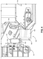
- material transfer vehicle 110 includes a frame 112 that is supported on the roadway surface by first wheel set 114 and second wheel set 116. Each of the wheel sets is driven by a hydraulic motor (not shown) that is supplied with fluid under pressure by one or more hydraulic pumps (also not shown).
- Vehicle 110 includes a material-receiving device comprising truck-receiving hopper 118 for receiving asphalt paving material from a delivery truck (not shown).
- Other material transfer vehicles may include another type of material-receiving device such as a windrow pick-up head (not shown) instead of the truck-receiving hopper.
- An auger (not shown, but substantially similar to auger 58) is mounted in the truck-receiving hopper and is adapted to assist in conveying asphalt paving material from the truck-receiving hopper into loading conveyor 120, which is supported at its lower end by a pair of wheel sets, one of which, wheel set 121, is shown in Figures 3-6 .
- Loading conveyor 120 conveys the asphalt paving material off of its output end 122 and into surge bin 124.
- the surge bin includes transverse auger 126 that is employed to mix the asphalt paving material in the surge bin in order to minimize segregation or separation of the aggregate portion of the asphalt paving material by size.
- surge conveyor 128, which is adapted to convey asphalt paving material upwardly out of the surge bin so that it may fall through chute 130 which is located over the input end of discharge conveyor 134.
- Discharge conveyor 134 is mounted for vertical pivotal movement about a pivot axis at its input end that is perpendicular to the page on which Figure 3 is displayed, as raised and lowered by a linear actuator.
- Discharge conveyor 134 is also adapted for side-to-side movement about a vertical axis by operation of one or more additional actuators.
- Asphalt paving material that falls through chute 130 onto discharge conveyor 134 is discharged through chute 136 at conveyor output end 138 into an asphalt receiving hopper of an asphalt paving machine (not shown).
- Hydraulic drive systems including hydraulic pumps and hydraulic motors are provided to drive the various augers and conveyors.
- Engine 140 provides the motive force for the hydraulic pumps that drive the hydraulic motors for the wheel sets, the augers, the various conveyors and the other components of the vehicle.
- Engine 140 is contained within engine compartment 142 located beneath discharge conveyor 134.
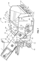
- Figure 7 illustrates a portion of material transfer vehicle 160, which is substantially similar to material transfer vehicle 110.
- Material transfer vehicle 160 includes a material-receiving device comprising truck-receiving hopper 180 for receiving asphalt paving material from a delivery truck (not shown).
- An auger (not shown) is mounted in truck-receiving hopper 180 and is adapted to assist in conveying asphalt paving material from truck-receiving hopper 180 into loading conveyor 182, which is supported at its lower end by a pair of wheel sets, one of which, wheel set 183, is shown in Figure 7 .
- Loading conveyor 182 conveys the asphalt paving material off of its output end (not shown, but substantially similar to output end 122 of loading conveyor 120 of material transfer vehicle 110) and into a surge bin (also not shown, but substantially similar to surge bin 124 of material transfer vehicle 110).
- the material-receiving device has a width W M measured transverse to the long axis A C of loading conveyor 120 that is greater that the width We of the loading conveyor (as shown in Figure 7 ), so that a recess is provided adjacent to the loading conveyor and behind the material-receiving device.
- Ground operator's station 144 is located adjacent to truck-receiving hopper 118 of material transfer vehicle 110 and adjacent to truck-receiving hopper 180 of material transfer vehicle 160. Preferably, the ground operator's station is located in a recess adjacent to the loading conveyor and behind the truck-receiving hopper.
- Ground operator's station 144 includes lower platform 146, transition support 148, vertical support 149 (shown in Figure 7 ) and seat 150 which is attached to seat platform 151.
- Transition support 149 connects lower platform 146 to vertical support 149, and seat platform 151 is attached to the upper end of vertical support 149.
- ground operator's control panel 152 Located directly across from seat 150 is ground operator's control panel 152, which is preferably mounted so that it can pivot or swing from the first position shown in the drawings (which is accessible to a ground operator standing on lower platform 146 or seated on seat 150) to a second position (not shown) which is accessible to a ground operator walking alongside truck-receiving hopper 118 or truck-receiving hopper 180 during a paving operation.
- Grab bar 154 is located so as to assist the ground operator in climbing onto lower platform 146
- back support 156 (best shown in Figure 7 ) is located to provide support for the ground operator's back when seated on seat 150.
- At least a portion of ground operator's station 144 may be mounted to or attached to wheel set 121 or wheel set 183.
- seat platform 151 and back support 156 are attached to wheel set 183.
- Lower platform 146 may also be attached to truck-receiving hopper 118 or truck-receiving hopper 180.
- ground operator “G” can stand on lower platform 146 and access control panel 152. Alternatively, ground operator “G” can sit on seat 150 as shown in Figure 6 . In either position, the ground operator can see clearly into truck-receiving hopper 118 or truck-receiving hopper 180 and the dump bed of the delivery truck.
- a plurality of tool support plates 192 are spaced across the top of sidewalls 184 and 186 of truck-receiving hopper 180 to create tool slots 194. Each of these tool slots cooperates with a pair of adjacent tool support plates to allow for secure storage of hand tools such as shovels 196 and 198.
- mounted atop loading conveyor 182 adjacent to truck-receiving hopper 180 are tool support walls 200 and 202 that are provided with aligned tool slots 204 which are adapted to support a rod-shaped tool such as cleaning bar 206 across the width of the loading conveyor.
- the invention thus provides a material transfer vehicle that includes a ground operator's station.
- This ground operator's station allows the ground operator to occupy a safe place with respect to the material transfer vehicle and the roadway, yet allows the ground operator to perform all the necessary functions of his job.
- the invention provides such a ground operator's station that allows the ground operator to get off his feet for a period of time during the paving operation.
- a preferred embodiment of the invention provides the ground operator with convenient and safe storage for hand tools such as shovels and cleaning bars.
Landscapes
- Engineering & Computer Science (AREA)
- Architecture (AREA)
- Civil Engineering (AREA)
- Structural Engineering (AREA)
- Road Paving Machines (AREA)
Claims (8)
- Materialtransferfahrzeug (110, 160), umfassend:a) eine Materialaufnahmevorrichtung (118, 180), die dazu angepasst ist, Asphalt-Straßenbelagsmaterial aufzunehmen; undb) ein Ladeband (120, 182), das mit der Materialaufnahmevorrichtung (118, 180) wirksam verbunden und dazu angepasst ist, Asphalt-Straßenbelagsmaterial von der Materialaufnahmevorrichtung (118, 180) aufzunehmen;wobei das Ladeband (120, 182) eine Längsachse und eine Breite (WC) hat, die quer zur Längsachse gemessen wird, und die Materialaufnahmevorrichtung (118, 180) eine Breite (WM) hat, die quer zur Längsachse des Ladebands (120, 182) gemessen wird, die größer als die Breite (WC) des Ladebands (120, 182) ist, sodass neben dem Ladeband (120, 182) und hinter der Materialaufnahmevorrichtung (118, 180) eine Ausnehmung geschaffen wird;dadurch gekennzeichnet, dass das Materialtransferfahrzeug ferner umfasst:
c) eine Maschinenführer-Station (144), die in der Ausnehmung neben dem Ladeband (120, 182) und hinter der Materialaufnahmevorrichtung (118, 180) angeordnet ist, wobei die Maschinenführer-Station (144) umfasst:i) eine untere Plattform (146), auf der der Maschinenführer stehen kann;ii) einen Sitz (150), auf dem der Maschinenführer sitzen kann. - Materialtransferfahrzeug (110, 160) gemäß Anspruch 1, wobei die Maschinenführer-Station (144) ferner umfasst:a) eine senkrechte Stütze (149);b) eine Übergangsstütze (148), die die untere Plattform (146) mit der senkrechten Stütze (149) verbindet;c) eine Sitzplattform (151), auf der der Sitz (150) angebracht ist, wobei die Sitzplattform (151) an dem oberen Ende der senkrechten Stütze (149) befestigt ist.
- Materialtransferfahrzeug (110, 160) gemäß Anspruch 1, das eine Maschinenführer-Steuerkonsole (152) aufweist, die dem Sitz (150) gegenüber angebracht ist, wobei die Maschinenführer-Steuerkonsole (152) dazu angepasst ist, von einer ersten Position, die für einen auf der unteren Plattform (146) stehenden oder auf dem Sitz (150) sitzenden Maschinenführer zugänglich ist, zu einer zweiten Position dreh- oder schwenkbar ist, die für einen neben der Materialaufnahmevorrichtung (118, 180) gehenden Maschinenführer zugänglich ist.
- Materialtransferfahrzeug (110, 160) gemäß Anspruch 1, wobei:a) das Ladeband (120, 182) an seinem unteren Ende von einem Radsatz (121, 183) abgestützt wird;b) mindestens ein Teil der Maschinenführer-Station (144) an dem Radsatz (121, 183) befestigt ist, der das untere Ende des Ladebands (120, 182) abstützt.
- Materialtransferfahrzeug (110, 160) gemäß Anspruch 1, wobei die Maschinenführer-Station (144) ferner umfasst:a) einen Haltegriff (154), der dazu angepasst ist, den Maschinenführer dabei zu unterstützen, auf die untere Plattform (146) zu steigen;b) eine Rückenstütze (156), die dazu angepasst ist, dem Rücken des Maschinenführers Halt zu bieten, wenn dieser auf dem Sitz (150) sitzt.
- Materialtransferfahrzeug (110, 160) gemäß Anspruch 1, wobei die untere Plattform (146) der Maschinenführer-Station (144) an der Materialaufnahmevorrichtung (118, 180) befestigt ist.
- Materialtransferfahrzeug (110, 160) gemäß Anspruch 1:a) wobei die Materialaufnahmevorrichtung (118, 180) eine Seitenwand (184, 186) aufweist;b) die eine Mehrzahl von Werkzeugträgerplatten (192) aufweist, die über die Oberseite der Seitenwand (184, 186) der Materialaufnahmevorrichtung (118, 180) beabstandet sind, um mindestens einen Werkzeugschlitz (194) zwischen einem Paar benachbarter Werkzeugträgerplatten (192) zu schaffen, wobei der Werkzeugschlitz (194) mit den Werkzeugträgerplatten (192) zusammenarbeitet, um eine sichere Lagerung für ein Handwerkzeug zu erlauben.
- Materialtransferfahrzeug (110, 160) gemäß Anspruch 1, das ein Paar Werkzeugträgerwände (200, 202) aufweist, die oben auf dem Ladeband (120, 182) angebracht sind, wobei die Werkzeugträgerwände (200, 202) ausgerichtete Werkzeugschlitze (204) aufweisen, die dazu angepasst sind, ein stangenartiges Werkzeug über die Breite des Ladebands (120, 182) zu tragen.
Applications Claiming Priority (3)
| Application Number | Priority Date | Filing Date | Title |
|---|---|---|---|
| US201962890829P | 2019-08-23 | 2019-08-23 | |
| US201962941059P | 2019-11-27 | 2019-11-27 | |
| PCT/US2020/045899 WO2021041033A1 (en) | 2019-08-23 | 2020-08-12 | Material transfer vehicle with ground operator station |
Publications (3)
| Publication Number | Publication Date |
|---|---|
| EP4018040A1 EP4018040A1 (de) | 2022-06-29 |
| EP4018040A4 EP4018040A4 (de) | 2023-09-13 |
| EP4018040B1 true EP4018040B1 (de) | 2024-10-09 |
Family
ID=74646700
Family Applications (1)
| Application Number | Title | Priority Date | Filing Date |
|---|---|---|---|
| EP20857737.9A Active EP4018040B1 (de) | 2019-08-23 | 2020-08-12 | Materialtransferfahrzeug mit bodenbedienstation |
Country Status (6)
| Country | Link |
|---|---|
| US (1) | US11866888B2 (de) |
| EP (1) | EP4018040B1 (de) |
| AU (1) | AU2020340229B2 (de) |
| CA (1) | CA3147777A1 (de) |
| ES (1) | ES3006452T3 (de) |
| WO (1) | WO2021041033A1 (de) |
Families Citing this family (3)
| Publication number | Priority date | Publication date | Assignee | Title |
|---|---|---|---|---|
| EP4018040B1 (de) | 2019-08-23 | 2024-10-09 | Roadtec, Inc. | Materialtransferfahrzeug mit bodenbedienstation |
| US12091109B2 (en) * | 2020-07-20 | 2024-09-17 | DM Carts LLC | Cart with unloading conveyor |
| CN114368068A (zh) * | 2021-04-26 | 2022-04-19 | 长安大学 | 一种防止拌合站集料离析装置 |
Family Cites Families (17)
| Publication number | Priority date | Publication date | Assignee | Title |
|---|---|---|---|---|
| EP0089385A1 (de) * | 1982-03-19 | 1983-09-28 | CASE VIBROMAX GmbH & Co. KG | Fahrerplatz für Tandemwalze |
| US4765772A (en) * | 1987-05-29 | 1988-08-23 | Angelo Benedetti, Inc. | Method and apparatus for filling voids in recycled asphalt |
| US5035534A (en) | 1987-08-25 | 1991-07-30 | Barber-Greene Company | Apparatus for transferring an asphalt-aggregate mixture |
| US5015120A (en) * | 1987-08-25 | 1991-05-14 | Barber-Greene Company | Methods and apparatus for making an asphalt-aggregate pavement |
| US5470175A (en) | 1994-05-16 | 1995-11-28 | Spudnik Equipment Company | Apparatus and methods for efficient and precise placement of discrete quantities of materials adjacent to the apparatus |
| US5553968A (en) * | 1994-09-29 | 1996-09-10 | Astec Industries, Inc. | Method and apparatus for conveying and desegregating aggregate |
| US5533828A (en) | 1994-09-29 | 1996-07-09 | Astec Industries, Inc. | Method and apparatus for discharging paving materials on top of distributing auger |
| EP1075569A1 (de) * | 1998-05-01 | 2001-02-14 | Interstate Highway Construction | Vorrichtung und verfahren für integriertes markieren von strassenbelag und dazugehörende techniken |
| US6345932B1 (en) * | 1999-02-05 | 2002-02-12 | Ingersoll-Rand Company | System for alternately operating steering and offset mechanisms of compacting vehicle |
| US6688450B2 (en) * | 2001-04-30 | 2004-02-10 | Blaw-Knox Construction Equipment Corporation | Mobile conveyor for paving vehicles |
| US7316520B2 (en) * | 2003-04-21 | 2008-01-08 | Semmaterials, L.P. | Low surface area shearing device |
| US7134806B2 (en) * | 2004-10-26 | 2006-11-14 | Her Majesty the Queen in right of the Province of Saskatchewan, as represented by the Minister of Highways and Transportation | Repairing road surfaces |
| US7160056B1 (en) * | 2005-03-11 | 2007-01-09 | Roadtee, Inc. | Material transfer vehicle for use in asphalt paving |
| US8262004B2 (en) * | 2005-05-31 | 2012-09-11 | Sno-Way International, Inc. | Hopper spreader/sprayer apparatus |
| US10046798B2 (en) * | 2016-09-02 | 2018-08-14 | David Allan Reeves | Foot controlled stand up zero turn radius utility vehicle |
| CA3036806C (en) * | 2016-10-13 | 2021-05-18 | Roadtec, Inc. | Access stairway for material transfer vehicle |
| EP4018040B1 (de) | 2019-08-23 | 2024-10-09 | Roadtec, Inc. | Materialtransferfahrzeug mit bodenbedienstation |
-
2020
- 2020-08-12 EP EP20857737.9A patent/EP4018040B1/de active Active
- 2020-08-12 CA CA3147777A patent/CA3147777A1/en active Pending
- 2020-08-12 ES ES20857737T patent/ES3006452T3/es active Active
- 2020-08-12 US US16/991,476 patent/US11866888B2/en active Active
- 2020-08-12 AU AU2020340229A patent/AU2020340229B2/en active Active
- 2020-08-12 WO PCT/US2020/045899 patent/WO2021041033A1/en not_active Ceased
Also Published As
| Publication number | Publication date |
|---|---|
| AU2020340229A1 (en) | 2022-03-31 |
| WO2021041033A1 (en) | 2021-03-04 |
| EP4018040A1 (de) | 2022-06-29 |
| AU2020340229B2 (en) | 2025-07-24 |
| US11866888B2 (en) | 2024-01-09 |
| ES3006452T3 (en) | 2025-03-18 |
| EP4018040A4 (de) | 2023-09-13 |
| US20210054580A1 (en) | 2021-02-25 |
| CA3147777A1 (en) | 2021-03-04 |
Similar Documents
| Publication | Publication Date | Title |
|---|---|---|
| AU2018278095B2 (en) | Quick-change attachment for material transfer vehicle | |
| US10760226B2 (en) | Material placer and high volume supply hopper | |
| EP4018040B1 (de) | Materialtransferfahrzeug mit bodenbedienstation | |
| EP4034710B1 (de) | Strassenbearbeitungsmaschine mit ausgangsleuchtsystem | |
| AU2018328001B2 (en) | Combination door/platform for maintenance access for conveyor of material transfer vehicle | |
| US20210155424A1 (en) | Asphalt receiving vehicle with guidance lights for supply trucks | |
| CA3121197C (en) | MATERIAL TRANSFER VEHICLE EQUIPPED WITH A MOBILE OPERATOR PLATFORM | |
| US20210107738A1 (en) | Material transfer vehicle with modular engine assembly |
Legal Events
| Date | Code | Title | Description |
|---|---|---|---|
| STAA | Information on the status of an ep patent application or granted ep patent |
Free format text: STATUS: THE INTERNATIONAL PUBLICATION HAS BEEN MADE |
|
| PUAI | Public reference made under article 153(3) epc to a published international application that has entered the european phase |
Free format text: ORIGINAL CODE: 0009012 |
|
| STAA | Information on the status of an ep patent application or granted ep patent |
Free format text: STATUS: REQUEST FOR EXAMINATION WAS MADE |
|
| 17P | Request for examination filed |
Effective date: 20220309 |
|
| AK | Designated contracting states |
Kind code of ref document: A1 Designated state(s): AL AT BE BG CH CY CZ DE DK EE ES FI FR GB GR HR HU IE IS IT LI LT LU LV MC MK MT NL NO PL PT RO RS SE SI SK SM TR |
|
| DAV | Request for validation of the european patent (deleted) | ||
| DAX | Request for extension of the european patent (deleted) | ||
| P01 | Opt-out of the competence of the unified patent court (upc) registered |
Effective date: 20230526 |
|
| REG | Reference to a national code |
Ref country code: DE Ref legal event code: R079 Free format text: PREVIOUS MAIN CLASS: E01C0019000000 Ipc: E01C0019480000 Ref document number: 602020039294 Country of ref document: DE |
|
| A4 | Supplementary search report drawn up and despatched |
Effective date: 20230817 |
|
| RIC1 | Information provided on ipc code assigned before grant |
Ipc: B62D 51/02 20060101ALI20230810BHEP Ipc: B62D 51/00 20060101ALI20230810BHEP Ipc: E01C 19/48 20060101AFI20230810BHEP |
|
| GRAP | Despatch of communication of intention to grant a patent |
Free format text: ORIGINAL CODE: EPIDOSNIGR1 |
|
| STAA | Information on the status of an ep patent application or granted ep patent |
Free format text: STATUS: GRANT OF PATENT IS INTENDED |
|
| INTG | Intention to grant announced |
Effective date: 20240404 |
|
| GRAS | Grant fee paid |
Free format text: ORIGINAL CODE: EPIDOSNIGR3 |
|
| GRAA | (expected) grant |
Free format text: ORIGINAL CODE: 0009210 |
|
| STAA | Information on the status of an ep patent application or granted ep patent |
Free format text: STATUS: THE PATENT HAS BEEN GRANTED |
|
| AK | Designated contracting states |
Kind code of ref document: B1 Designated state(s): AL AT BE BG CH CY CZ DE DK EE ES FI FR GB GR HR HU IE IS IT LI LT LU LV MC MK MT NL NO PL PT RO RS SE SI SK SM TR |
|
| REG | Reference to a national code |
Ref country code: CH Ref legal event code: EP |
|
| REG | Reference to a national code |
Ref country code: DE Ref legal event code: R096 Ref document number: 602020039294 Country of ref document: DE |
|
| REG | Reference to a national code |
Ref country code: IE Ref legal event code: FG4D |
|
| REG | Reference to a national code |
Ref country code: LT Ref legal event code: MG9D |
|
| REG | Reference to a national code |
Ref country code: SE Ref legal event code: TRGR |
|
| REG | Reference to a national code |
Ref country code: NL Ref legal event code: MP Effective date: 20241009 |
|
| REG | Reference to a national code |
Ref country code: AT Ref legal event code: MK05 Ref document number: 1730724 Country of ref document: AT Kind code of ref document: T Effective date: 20241009 |
|
| PG25 | Lapsed in a contracting state [announced via postgrant information from national office to epo] |
Ref country code: NL Free format text: LAPSE BECAUSE OF FAILURE TO SUBMIT A TRANSLATION OF THE DESCRIPTION OR TO PAY THE FEE WITHIN THE PRESCRIBED TIME-LIMIT Effective date: 20241009 |
|
| REG | Reference to a national code |
Ref country code: ES Ref legal event code: FG2A Ref document number: 3006452 Country of ref document: ES Kind code of ref document: T3 Effective date: 20250318 |
|
| PG25 | Lapsed in a contracting state [announced via postgrant information from national office to epo] |
Ref country code: NL Free format text: LAPSE BECAUSE OF FAILURE TO SUBMIT A TRANSLATION OF THE DESCRIPTION OR TO PAY THE FEE WITHIN THE PRESCRIBED TIME-LIMIT Effective date: 20241009 |
|
| PG25 | Lapsed in a contracting state [announced via postgrant information from national office to epo] |
Ref country code: PT Free format text: LAPSE BECAUSE OF FAILURE TO SUBMIT A TRANSLATION OF THE DESCRIPTION OR TO PAY THE FEE WITHIN THE PRESCRIBED TIME-LIMIT Effective date: 20250210 Ref country code: IS Free format text: LAPSE BECAUSE OF FAILURE TO SUBMIT A TRANSLATION OF THE DESCRIPTION OR TO PAY THE FEE WITHIN THE PRESCRIBED TIME-LIMIT Effective date: 20250209 Ref country code: HR Free format text: LAPSE BECAUSE OF FAILURE TO SUBMIT A TRANSLATION OF THE DESCRIPTION OR TO PAY THE FEE WITHIN THE PRESCRIBED TIME-LIMIT Effective date: 20241009 |
|
| PG25 | Lapsed in a contracting state [announced via postgrant information from national office to epo] |
Ref country code: FI Free format text: LAPSE BECAUSE OF FAILURE TO SUBMIT A TRANSLATION OF THE DESCRIPTION OR TO PAY THE FEE WITHIN THE PRESCRIBED TIME-LIMIT Effective date: 20241009 |
|
| PG25 | Lapsed in a contracting state [announced via postgrant information from national office to epo] |
Ref country code: BG Free format text: LAPSE BECAUSE OF FAILURE TO SUBMIT A TRANSLATION OF THE DESCRIPTION OR TO PAY THE FEE WITHIN THE PRESCRIBED TIME-LIMIT Effective date: 20241009 |
|
| PG25 | Lapsed in a contracting state [announced via postgrant information from national office to epo] |
Ref country code: NO Free format text: LAPSE BECAUSE OF FAILURE TO SUBMIT A TRANSLATION OF THE DESCRIPTION OR TO PAY THE FEE WITHIN THE PRESCRIBED TIME-LIMIT Effective date: 20250109 |
|
| PG25 | Lapsed in a contracting state [announced via postgrant information from national office to epo] |
Ref country code: LV Free format text: LAPSE BECAUSE OF FAILURE TO SUBMIT A TRANSLATION OF THE DESCRIPTION OR TO PAY THE FEE WITHIN THE PRESCRIBED TIME-LIMIT Effective date: 20241009 Ref country code: GR Free format text: LAPSE BECAUSE OF FAILURE TO SUBMIT A TRANSLATION OF THE DESCRIPTION OR TO PAY THE FEE WITHIN THE PRESCRIBED TIME-LIMIT Effective date: 20250110 Ref country code: AT Free format text: LAPSE BECAUSE OF FAILURE TO SUBMIT A TRANSLATION OF THE DESCRIPTION OR TO PAY THE FEE WITHIN THE PRESCRIBED TIME-LIMIT Effective date: 20241009 |
|
| PG25 | Lapsed in a contracting state [announced via postgrant information from national office to epo] |
Ref country code: PL Free format text: LAPSE BECAUSE OF FAILURE TO SUBMIT A TRANSLATION OF THE DESCRIPTION OR TO PAY THE FEE WITHIN THE PRESCRIBED TIME-LIMIT Effective date: 20241009 |
|
| PG25 | Lapsed in a contracting state [announced via postgrant information from national office to epo] |
Ref country code: RS Free format text: LAPSE BECAUSE OF FAILURE TO SUBMIT A TRANSLATION OF THE DESCRIPTION OR TO PAY THE FEE WITHIN THE PRESCRIBED TIME-LIMIT Effective date: 20250109 |
|
| PG25 | Lapsed in a contracting state [announced via postgrant information from national office to epo] |
Ref country code: SM Free format text: LAPSE BECAUSE OF FAILURE TO SUBMIT A TRANSLATION OF THE DESCRIPTION OR TO PAY THE FEE WITHIN THE PRESCRIBED TIME-LIMIT Effective date: 20241009 |
|
| PG25 | Lapsed in a contracting state [announced via postgrant information from national office to epo] |
Ref country code: DK Free format text: LAPSE BECAUSE OF FAILURE TO SUBMIT A TRANSLATION OF THE DESCRIPTION OR TO PAY THE FEE WITHIN THE PRESCRIBED TIME-LIMIT Effective date: 20241009 |
|
| REG | Reference to a national code |
Ref country code: DE Ref legal event code: R097 Ref document number: 602020039294 Country of ref document: DE |
|
| PG25 | Lapsed in a contracting state [announced via postgrant information from national office to epo] |
Ref country code: EE Free format text: LAPSE BECAUSE OF FAILURE TO SUBMIT A TRANSLATION OF THE DESCRIPTION OR TO PAY THE FEE WITHIN THE PRESCRIBED TIME-LIMIT Effective date: 20241009 |
|
| PG25 | Lapsed in a contracting state [announced via postgrant information from national office to epo] |
Ref country code: RO Free format text: LAPSE BECAUSE OF FAILURE TO SUBMIT A TRANSLATION OF THE DESCRIPTION OR TO PAY THE FEE WITHIN THE PRESCRIBED TIME-LIMIT Effective date: 20241009 |
|
| PG25 | Lapsed in a contracting state [announced via postgrant information from national office to epo] |
Ref country code: SK Free format text: LAPSE BECAUSE OF FAILURE TO SUBMIT A TRANSLATION OF THE DESCRIPTION OR TO PAY THE FEE WITHIN THE PRESCRIBED TIME-LIMIT Effective date: 20241009 |
|
| PG25 | Lapsed in a contracting state [announced via postgrant information from national office to epo] |
Ref country code: CZ Free format text: LAPSE BECAUSE OF FAILURE TO SUBMIT A TRANSLATION OF THE DESCRIPTION OR TO PAY THE FEE WITHIN THE PRESCRIBED TIME-LIMIT Effective date: 20241009 |
|
| PG25 | Lapsed in a contracting state [announced via postgrant information from national office to epo] |
Ref country code: IT Free format text: LAPSE BECAUSE OF FAILURE TO SUBMIT A TRANSLATION OF THE DESCRIPTION OR TO PAY THE FEE WITHIN THE PRESCRIBED TIME-LIMIT Effective date: 20241009 |
|
| PLBE | No opposition filed within time limit |
Free format text: ORIGINAL CODE: 0009261 |
|
| STAA | Information on the status of an ep patent application or granted ep patent |
Free format text: STATUS: NO OPPOSITION FILED WITHIN TIME LIMIT |
|
| 26N | No opposition filed |
Effective date: 20250710 |
|
| PGFP | Annual fee paid to national office [announced via postgrant information from national office to epo] |
Ref country code: ES Payment date: 20250904 Year of fee payment: 6 |
|
| PGFP | Annual fee paid to national office [announced via postgrant information from national office to epo] |
Ref country code: DE Payment date: 20250828 Year of fee payment: 6 |
|
| PGFP | Annual fee paid to national office [announced via postgrant information from national office to epo] |
Ref country code: GB Payment date: 20250731 Year of fee payment: 6 |
|
| PGFP | Annual fee paid to national office [announced via postgrant information from national office to epo] |
Ref country code: SE Payment date: 20250817 Year of fee payment: 6 |
|
| REG | Reference to a national code |
Ref country code: CH Ref legal event code: H13 Free format text: ST27 STATUS EVENT CODE: U-0-0-H10-H13 (AS PROVIDED BY THE NATIONAL OFFICE) Effective date: 20260324 |
|
| PG25 | Lapsed in a contracting state [announced via postgrant information from national office to epo] |
Ref country code: MC Free format text: LAPSE BECAUSE OF FAILURE TO SUBMIT A TRANSLATION OF THE DESCRIPTION OR TO PAY THE FEE WITHIN THE PRESCRIBED TIME-LIMIT Effective date: 20241009 |
|
| PG25 | Lapsed in a contracting state [announced via postgrant information from national office to epo] |
Ref country code: LU Free format text: LAPSE BECAUSE OF NON-PAYMENT OF DUE FEES Effective date: 20250812 |