EP4018865A1 - Casque gonflable - Google Patents
Casque gonflable Download PDFInfo
- Publication number
- EP4018865A1 EP4018865A1 EP21216460.2A EP21216460A EP4018865A1 EP 4018865 A1 EP4018865 A1 EP 4018865A1 EP 21216460 A EP21216460 A EP 21216460A EP 4018865 A1 EP4018865 A1 EP 4018865A1
- Authority
- EP
- European Patent Office
- Prior art keywords
- inflatable
- aperture
- helmet
- elongate member
- members
- Prior art date
- Legal status (The legal status is an assumption and is not a legal conclusion. Google has not performed a legal analysis and makes no representation as to the accuracy of the status listed.)
- Granted
Links
Images




Classifications
-
- A—HUMAN NECESSITIES
- A42—HEADWEAR
- A42B—HATS; HEAD COVERINGS
- A42B3/00—Helmets; Helmet covers ; Other protective head coverings
- A42B3/04—Parts, details or accessories of helmets
- A42B3/10—Linings
- A42B3/12—Cushioning devices
- A42B3/121—Cushioning devices with at least one layer or pad containing a fluid
- A42B3/122—Cushioning devices with at least one layer or pad containing a fluid inflatable
-
- A—HUMAN NECESSITIES
- A42—HEADWEAR
- A42B—HATS; HEAD COVERINGS
- A42B3/00—Helmets; Helmet covers ; Other protective head coverings
- A42B3/32—Collapsible helmets; Helmets made of separable parts ; Helmets with movable parts, e.g. adjustable
- A42B3/322—Collapsible helmets
Definitions
- the invention relates to inflatable helmets.
- the inflatable helmet may be useful as a protective helmet, for cycling, motorcycling, or for use as protective wear during sports and any other activities in which protective wear may be required or be beneficial. Such other activities may include skateboarding, rollerblading, skating, and kitesurfing.
- cycling helmets are formed of solid, rigid material, and therefore have a particular permanent size and volume. This can be inconvenient, particularly because there may be little room to store a conventional cycling helmet. It is desirable to have a cycling helmet that is inflatable, and can therefore collapse and be compressed to a compact form when not in use, and re-inflated for use. However, inflatable structures often lack strength and rigidity.
- a known inflatable helmet is described in European Patent No. EP3232844 . This uses a lattice-like structure to form a rigid structure.
- the inventors have appreciated a need for an inflatable or collapsible helmet that is capable of withstanding structural forces of the conventional impact tests required for cycling helmets (for example, EN1078).
- the inventors have further appreciated a need for a helmet designed to be manufactured effectively and efficiently.
- the inventors have further appreciated a need for a helmet that may be stored easily and effectively when not in use.
- the present invention provides an inflatable helmet.
- the inflatable helmet comprises a plurality of elongate members.
- Each elongate member comprises at least one chamber wall defining an inflatable chamber.
- At least two (or a pair of) adjacent elongate members are in fluid communication with each other.
- the plurality of elongate members is inflatable so as to adjust the inflatable helmet from a collapsed state to an inflated state. In an inflated state, at least one pair of adjacent elongate members abut each other along at least a portion of their respective chamber walls.
- the helmet of preferred embodiments of the present invention may be capable of being collapsed or deflated and conveniently stored away in a collapsed state until a user needs to use to it by inflating the helmet to an inflated state.
- the helmet of preferred embodiments of the present invention may also provide improved structural rigidity and impact performance during use in an inflated state.
- adjacent elongate members of the plurality of elongate members abut each other along at least a longitudinal portion of their respective chamber walls.
- adjacent elongate members are either touching or are coupled to each other along at least a longitudinal portion of their respective chamber walls.
- adjacent elongate members directly abut each other along at least a longitudinal portion of their respective chamber walls.
- the term directly abut' preferably refers to the fact that two elements or components are touching or are coupled to each other, with no other intermediate elements or components, or even gaps, between them in locations where they are abutting.
- the (at least one pair) adjacent elongate members in an inflated state, the (at least one pair) adjacent elongate members abut each other along a majority of the length of their respective chamber walls.
- the inflatable helmet is collapsible from an inflated state to a collapsed (or deflated) state.
- the plurality of elongate members is deflatable so as to adjust the inflatable helmet from an inflated state to a collapsed state. This advantageously ensures that the inflatable helmet can be stored away after being inflated to an inflated state from a collapsed state.
- each of the elongate members is substantially flattened such that the shape of the helmet in a collapsed state is substantially flatter than the shape of the helmet in an inflated state.
- the shape of the helmet in a collapsed state may be substantially flatter in a transverse direction than the shape of the helmet in an inflated state.
- adjacent elongate members are joined or coupled to each other at at least one location or portion of their respective chamber walls.
- adjacent elongate members are joined or coupled to each other at at least one longitudinal location or portion of their respective chamber walls.
- the remaining longitudinal portions, or length, of the respective chamber walls of joined, adjacent elongate members may not be coupled or joined to each other.
- the remaining longitudinal portions of the respective chamber walls of joined, adjacent elongate members may or may not abut each other in the collapsed state.
- in an inflated state such remaining portions of the respective chamber walls of adjacent elongate members abut each other in an inflated state.
- some of such remaining portions of the respective chamber walls of adjacent elongate members do not abut each other in a collapsed state.
- first portion (or first portions) of a chamber wall comprises, or consists of, a portion of the chamber wall that is coupled to another chamber wall.
- first portion (or first portions) of a chamber wall comprises, or consists of, a portion of the chamber wall that is coupled to another chamber wall.
- adjacent elongate members may abut each other along a second portion of their respective chamber walls.
- adjacent elongate members may abut each other along a second portion of their respective chamber walls.
- Such a second portion of a chamber wall comprises, or consists of, a portion of the chamber wall that is not coupled or joined to another chamber wall.
- Such a second portion of a chamber wall may comprise the majority of the length of the chamber wall.
- such a second portion of a chamber wall which is configured to abut a second portion of the chamber wall of an adjacent elongate member, comprises at least 50 percent of the length of the chamber wall.
- Such a second portion of a chamber wall may comprise at least 60 percent of the length of the chamber wall.
- Such a second portion of a chamber wall may comprise at least 75 percent of the length of the chamber wall.
- adjacent elongate members may abut each other in a collapsed or deflated state, they are configured to abut each other along longer portions of their respective chamber walls in an inflated state.
- the elongate, inflatable members are wider in an inflated state than in a collapsed state.
- the fluidly connected elongate members abut each other more (that is, along a greater length of their respective chamber walls) in an inflated state than in a collapsed state.
- Such an increase in abutment ensures there is more contact amongst adjacent elongate members in an inflated state, which advantageously ensures the helmet can sustain impact and minimise transfer of such an impact to a user's head, while also ensuring that the helmet can be stored away in a more compact form.
- the elongate members extend substantially along a longitudinal direction of the helmet.
- the elongate members of the helmet preferably wholly or partially extend between a rear end of the helmet and a front end of the helmet.
- the elongate members are preferably configured to expand laterally (that is, along a transverse direction of the helmet extending between both the left and right sides) or transversely. Accordingly, a width of each of the elongate members may be greater in an inflated state than a width of each of the elongate members in a collapsed or deflated state.
- the elongate members may be substantially parallel to each other, at least in a collapsed state of the inflatable helmet. Providing the elongate members substantially parallel to each other at least in a collapsed state of the helmet, ensures that the width of the helmet is minimised so that the helmet can occupy less space and be stored easily by a user.
- Each elongate member may comprise at least one aperture defined in the chamber wall.
- the at least one aperture of an elongate member may be fluidly connected to at least one corresponding aperture of an adjacent elongate member. This ensures there is direct abutment between adjacent elongate members in an inflated state, while establishing a fluid communication between such elongate members so that they can be inflated.
- the at least one aperture of an elongate member may be coupled to at least one corresponding aperture of an adjacent elongate member.
- the apertures are preferably coupled by welding, as described in further detail in the present disclosure.
- the plurality of elongate members may comprise two external (or outer) elongate members and at least one internal (or inner) elongate member located between the external elongate members.
- the at least one internal elongate member may comprise at least one first aperture located on a first side of the inflatable chamber and at least one second aperture located on an opposing second side of the inflatable chamber.
- the at least one first aperture of an internal elongate member may be fluidly connected to at least one corresponding aperture of an adjacent elongate member.
- the at least one second aperture of an internal elongate member may be fluidly connected to at least one corresponding aperture of another adjacent elongate member.
- the inflatable helmet comprises at least five internal elongate members.
- the inflatable helmet comprises at least eight internal elongate members.
- the inflatable helmet may comprise two external elongate members and at least nine internal elongate members. Some of the internal elongate members are shorter in length than other internal elongate members and the external elongate members.
- Each elongate member may comprise a plurality of apertures defined in the chamber wall.
- the apertures of the plurality of apertures may be longitudinally spaced amongst each other. Providing a plurality of longitudinally-spaced apertures ensures that adjacent elongate members can be fluidly connected, while providing an effective and quick inflation of the helmet.
- the portion of the chamber wall surrounding the at least one aperture of an elongate member may be coupled to the portion of the chamber wall surrounding the at least one corresponding aperture of an adjacent elongate member such that an airtight seal is provided around the apertures.
- each elongate member may comprise an inner layer and an outer layer. This enhances the structural integrity of the chamber walls.
- a portion of the chamber wall surrounding the at least one aperture may comprise one of the inner layer and the outer layer.
- a portion of the chamber wall surrounding the at least one aperture may consist of the inner layer or the outer layer.
- Such a portion of the chamber wall may correspond to a portion of the chamber wall located at the periphery of an aperture.
- a portion of the outer layer surrounding the at least one aperture may be removed to expose the inner layer.
- the chamber wall of each elongate member may comprise at least one longitudinal seam.
- the at least one longitudinal seam may be formed by joining a longitudinal portion of one of the inner layer and outer layer to another longitudinal portion of either the same one of the inner layer and outer layer or a different one of the inner layer and outer layer.
- the at least one longitudinal seam is formed by joining a longitudinal portion of an outer layer to another longitudinal portion of either the same outer layer or a different outer layer.
- the chamber wall of each elongate member comprises a first wall and a second wall. The first and second walls may be joined together by an upper longitudinal seam and a lower longitudinal seam.
- the chamber wall of each elongate member is defined by a single wall element, the edges of which are joined together to form at least one longitudinal seam, in order to form an inflatable chamber.
- each longitudinal seam is reinforced by a rib member.
- the reinforcing rib member may be coupled to each longitudinal seam.
- the rib member may enclose or encapsulate each longitudinal seam.
- Each elongate member may comprise at least one rib member.
- Each elongate member may comprise a lower rib member and an upper rib member, respectively corresponding to a lower longitudinal seam and an upper longitudinal seam.
- the inner layer may comprise an outer lamina of plastic material and an inner lamina of woven material.
- the outer layer may comprise an outer lamina of woven material and an inner lamina of plastic material. At least a portion of the inner lamina of the outer layer overlapping the outer lamina of the inner layer may be joined to the outer lamina of the inner layer such that an airtight seal is formed between the outer and inner layers of the chamber wall.
- an inflatable article may comprise a plurality of inflatable members. Each inflatable member may comprise at least one chamber wall defining an inflatable chamber. At least two adjacent inflatable members may be in fluid communication with each other.
- the plurality of inflatable members may be inflatable so as to adjust the inflatable article from a collapsed state to an inflated state. In an inflated state, at least one pair of adjacent inflatable members abut each other along at least a portion of their respective chamber walls.
- the inflatable members may be elongate members.
- in an inflated state at least one pair of adjacent elongate members abut each other along at least a portion of their respective chamber walls.
- the inflatable article may be a wearable article.
- Each inflatable member may comprise at least one aperture defined in the chamber wall.
- the at least one aperture of an inflatable member may be fluidly connected to at least one corresponding aperture of an adjacent inflatable member.
- the portion of the chamber wall surrounding the at least one aperture of an inflatable member may be coupled to the portion of the chamber wall surrounding the at least one corresponding aperture of an adjacent inflatable member such that an airtight seal is provided around the apertures.
- the chamber wall of each inflatable member may comprise an inner layer and an outer layer.
- a portion of the chamber wall surrounding the at least one aperture may consist of one of the inner layer and the outer layer.
- the inflatable article may be inflatable from a collapsed state to an inflated state.
- the inflatable article may be collapsible from an inflated state to a collapsed state.
- each of the inflatable members may be substantially flattened such that the shape of the article in a collapsed state is substantially flatter than the shape of the article in an inflated state.
- the inflatable members extend along a longitudinal direction of the article.
- some or all of the inflatable members are arranged substantially parallel to each other.
- Some or all of the inflatable members may be arranged substantially parallel to each other, in a collapsed state.
- the inflatable members of the inflatable article may be elongate members, with similar characteristics to those of the inflatable helmet described in the present disclosure.
- the chamber wall of each inflatable member may comprise at least one longitudinal seam.
- the at least one longitudinal seam may be formed by joining a longitudinal portion of one of the inner layer and outer layer to another longitudinal portion of either the same one of the inner layer and outer layer or a different one of the inner layer and outer layer.
- the at least one longitudinal seam is formed by joining a longitudinal portion of an outer layer to another longitudinal portion of either the same outer layer or a different outer layer.
- the inner layer may comprise an outer lamina of plastic material and an inner lamina of woven material.
- the outer layer may comprises an outer lamina of woven material and an inner lamina of plastic material. At least a portion of the inner lamina of the outer layer overlapping the outer lamina of the inner layer may be joined to the outer lamina of the inner layer such that an airtight seal is formed between the outer and inner layers of the chamber wall.
- any feature in one aspect of the invention may be applied to other aspects of the invention, in any appropriate combination.
- any, some and/or all features in one aspect may be applied to any, some and/or all features in any other aspect, in any appropriate combination.
- any method features provided in relation to the first aspect may be applied to any of the other aspects.
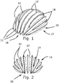
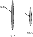
- a helmet 10 according to an embodiment of the present invention comprises a series of longitudinal members 12, 14, arranged side-by-side to each other.
- the helmet 10 has a generally curved with a concave inside shape and a convex outside shape, though somewhat flattened, with a front end 18 and rear end 19 and two side edges 20, and each longitudinal member 12, 14 being curved and aligned approximately longitudinally and generally parallel to its neighbouring members, but at an increasing inclination, so that the longitudinal members 12, 14 together form the curved profile of the helmet 10.
- Some longitudinal members 12 extend fully between the front edge 18 and rear edge 19, converging at those two regions.
- Other longitudinal members 14 are shorter, and occupy positions between the fully extending longitudinal members 12 that would otherwise be left between the fully extending longitudinal members 12 at the middle region of the helmet. All the longitudinal members 12 may be tapered towards there terminal ends so that they fit together in the hemispherical arrangement.
- Each longitudinal member 12, 14 is inflatable, having an airtight skin (or chamber wall) that defines an inflatable chamber, and the chambers of longitudinal members 12, 14 are in fluid communication with each other.
- the longitudinal members 12, 14 are shown fully inflated, so that they assume a helmet-like shape or profile.
- the longitudinal members 12 when the chambers of longitudinal members 12, 14 are evacuated, the longitudinal members 12 may be compressed or collapsed in a lateral direction so the longitudinal members 12, 14 and the helmet 10 as a whole attain a relatively flat state, the planar form of each longitudinal members 12, 14 being now parallel with every other flattened longitudinal member 12, 14. In this deflated, relatively flat state, the helmet 10 takes up little room and may more conveniently be stored.
- each longitudinal member 12, 14 comprises a chamber cavity 34 defined by a first wall 22 and a second wall 24.
- the first wall 22 and second wall 24 are joined along their respective upper edges and respective lower edges with a surface to surface connection 38, where material from the first wall 22 and second wall 24 are superimposed to form a seam.
- Each longitudinal member 12, 14 thus has two surface to surface connections 38, one running longitudinally along the outside of the helmet 10, and one running longitudinally along the inside of the helmet 10.
- Each surface to surface connection 38 is encapsulated along the length (or along the majority of the length) with a linear perimeter rib 35, 36, which provides further structural strength and rigidity to the longitudinal members, strengthens the surface to surface connection 38, spreads the load during impact across more of the chamber, and reduces friction under impact. A reduction in friction means an impact force will slide over the surface of the helmet rather than be absorbed by it.
- the inside linear perimeter rib 36 features a padded member 37 which extends along the inside linear perimeter rib 36 to provide a soft surface that sits on the user's head.
- the rib may be formed from nylon.
- each longitudinal member 12, 14 is joined to the members directly adjacent to it in fluid communication, so that the helmet 10 may be inflated or deflated by respectively introducing or letting out air in any one of the longitudinal members.
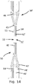
- the longitudinal members 12, 14 are joined by nodes 28 formed by apertures 30 in the walls 22, 24.
- the aperture 30 of a first wall 22 of one longitudinal member 12, 14 is joined to the aperture 30 of a second wall 24 of the adjacent longitudinal member 12, 14. This arrangement is repeated for each neighbouring pair of longitudinal members 12, 14.
- the material of the first and second walls of adjacent longitudinal members are superimposed with coincident edges, and joined in this region to form a surface to node connection 40.
- the surface to node connection 40 thus has a double layer of material, and is generally annular, the aperture 30 being generally circular.
- nodes 28 are located along the longitudinal members 12, 14 in a periodic manner.
- the nodes 28 formed with longitudinal member 12 are longitudinally spaced compared to the nodes 28 formed with longitudinal member 14. This means that air flow through nodes joining the longitudinal members cannot simply flow from one side of the helmet to the other in a straight line, but must take a convoluted path by having to travel longitudinally along the longitudinal member to the next node, with the path of air flow through the nodes being indicated by arrows a.
- This arrangement increases the resistance of the airflow, causing the helmet 10 to be stiffer in the event of an impact at a point on the helmet.
- nodes 28 may though be convenient to have some longitudinal members, such as the center-most longitudinal member 12 shown in Figure 9 , to have nodes 28 on each side of the longitudinal member 12. Such nodes 28are laterally aligned on both sides.
- the first and second walls 22, 24 are ideally formed from a double-layered material, each wall of the longitudinal member 12, 14 being formed from an interior (or inner) layer (or lamina) 26 and an exterior (or outer) layer (or lamina) 25.
- Each single layer itself ideally a laminate material, one possible embodiment of which is described in further detail in Figures 12 to 14 .
- each longitudinal member 12, 14 is removed in that region, so that the two adjoining interior layers 26 can be secured together.
- first wall 22 and second wall 24 of a longitudinal member 12, 14 at the surface to surface connection 38, the interior layer 26 of the first wall 22 and the second wall 24 are both removed, and the remaining exterior layer 25 of the first wall 22 and the second wall 24 are superimposed and welded to create a seam.
- the wall could be formed without the layer being present in that region.
- the nodes 28 are placed approximately at equidistant points from each other along the length of each longitudinal member, thus spreading the forces across the structure.
- An ideal material for the walls of the longitudinal members is a laminate material formed from a lamina of airtight thermoplastic polyurethane (TPU), and a lamina of woven plastic material such as Nylon 66. A single layer of this laminate material, provided both lamina are intact is itself airtight by virtue of the TPU.
- TPU thermoplastic polyurethane
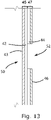
- a double layer material 50 can be conveniently formed by welding two such laminate material layers together, that is, a first sheet of laminar material 45, comprising a first lamina of TPU 42 and a first lamina of woven material 43, to a second sheet of laminar material 47, comprising a second lamina of TPU 44 and a second lamina of woven material 46, the first lamina of TPU 42 and the second lamina of TPU 44 arranged confronting each other.
- the first and second sheets 45, 47 need not be co-extensive, and in this example a region 51 is shown where the first sheet 45 extends beyond the edge of the second sheet 47. Such a region may run along the length of the material, for example along the first wall 22 where the seam 38 is to be formed with second wall 24.
- FIG. 13 shows a sheet of double layer wall material 50 where a cutaway hole 52 is formed through the second lamina of TPU 44 and second lamina of woven material 46 of the second sheet of laminar material 47 to expose the first lamina of TPU 42 of the adjoining face of the first sheet of laminar material 45.
- two similar sheets of double layer wall material 50, 50' may be brought together, with similar cutaway holes 52, 52' confronting each other, and the exposed portions of TPU 53, 54 pressed together and welded to form a join between the sheets of double layer wall material 50, 50'.
- a fluid communication can be established between two longitudinal members.
- a longitudinal member 12 has a first wall 22 and second wall 24 formed from the double layer wall material 50 shown in Figure 11 .
- the outermost laminae of TPU and woven material are removed to form a cutaway hole 52 to leave region having the structure shown in Figure 12 , with an exposed region 55 of TPU exposed.
- An aperture 30 is formed through the TPU and woven material in this exposed region 55.
- the other longitudinal member is similarly prepared with a cutaway hole located to confront cutaway hole 52, with the apertures aligned.
- the TPU in the two exposed regions 55 are pressed together and welded.
- the opposing surfaces of exposed TPU welding in this manner form a secure hermetically sealed join, and the aligned apertures 30 through the walls of the longitudinal members allow fluid communication between the longitudinal members in the manner previously described.
- the welding process for joining laminae of TPU arranged in confrontation may be high frequency (HF) welding.
- HF high frequency
- This process uses radio frequency energy to join the abutting TPU laminae of material due to the ultrasonic vibration of molecules within the TPU material, and gives a strength at the join which is equivalent to the base structural strength of the material itself.
- the resulting join between two laminae of TPU is also airtight.
- the node weld using this system is leak proof, is as strong as the actual base material and tested at BSI laboratory to pass an EN1078 structural drop test and repeat testing.
- Other forms of welding or joining may be suitable, such as heat welding or solvent welding may be used, provided the resulting welds or joins have sufficient strength and airtight sealing qualities.
- the laminae of woven material may have a weave direction, and this will typically give structural properties that vary dependant on direction.
- the first lamina of woven material 43 and the second lamina of woven material 46 may be arranged so that that the weave direction of the first lamina of woven material 43 is ideally rotated 45 degrees from the weave direction of the second lamina of woven material 46.
- the woven material may have both a weave and a weft, typically perpendicular to one another, so orienting one woven lamina at 45 degrees to the other ensures both the weave and weft of that lamina are differently oriented to both the weave and weft of the other woven lamina, providing good strength qualities in any direction.
- Other differing orientation angles of the two woven laminae may though be implemented.
- the double wall material provides strength for the chamber of each longitudinal member when inflated or in the stress of impact; it is also resistant to stretching.
- the upper perimeter of the inner material 26 is offset with respect to the outer material to leave an upper perimeter of only the outer material 25 around the edges. This then allows for the outer material 25 of the first wall 22 to be welded or laminated to the outer material 25 of the second wall 24 (the second wall being similar to the first wall, but having the lamina order reversed or reflected) to form the surface to surface connection 38 and thus the chamber as previously described, the same process is also used at the lower region of the longitudinal members 12, 14 to form the lower surface to surface connection.
- the resulting weld seams run longitudinally along the length of the helmet structure, forming a major structural element and becomes a rib member 35, 36 that helps constrain the forces under inflation, ultimately spreads loading forces under or during impact along the length of that particular chamber; that is, the rib stops the curved shape or profile of the longitudinal member from opening out or uncurling.
- the double laminae structure also allows for a slit to be created between the laminae so that the interior nodes can be accessed from inside the chamber to be welded to the next chamber from interior to interior if desired. Once the nodes are welded, the slit is then welded up.
- the slit is offset so the outer lamina slit intentionally misaligns with the inner lamina to be sure there is always at least one lamina of woven material on the surface.
- a weld connection point may be formed by removing a lamina of woven material and TPU material from aligned portions of double walled material and welding the confronting TPU surfaces as for forming a node, but without forming a through hole so that the connection is blank or blind, so that the adjacent longitudinal members are bonded together but are not in fluid communication at this point.
- Both nodes having through hole connections, and blind weld connection points may be placed at any point along the chamber with a minimum of design alteration; the removal of one lamina of woven material and one lamina of TPU material from the double wall to form a node may be carried out.
- the size of the aperture determines the resistance to airflow during an impact, allow the strength of the chamber and structure to be predetermined.
- the diameter of the aperture may be at least about 1 mm.
- the diameter of the aperture is at least about 3 mm.
- the diameter of the aperture may be less than or equal to about 7 mm.
- the diameter of the aperture is less than or equal to about 6 mm.
- the diameter of the aperture may be between about 1 mm and about 7 mm.
- the diameter of the aperture is between about 3 mm and about 6 mm.
- the diameter of the aperture is about 5 mm.
- the helmet is formed as a completely sealed unit that can be inflated and deflated, preferably repeatedly. Therefore, the helmet preferably includes at least one air inlet port (not shown) that can be used to inflate or deflate the helmet.
- the air inlet port or valve may provide a fluid communication with at least one of the elongate members of the helmet.
- the air inlet port may be configured to allow air to enter and exit the helmet. Alternatively, a separate or additional air outlet port may be provided on the helmet to allow air to exit the helmet.
- an air inlet (or outlet) port is provided on one of the internal elongate members.
- the air inlet (or outlet) port is provided on one of the elongate members that is located on, or in the vicinity of, a central portion of the helmet. This may ensure that the helmet is evenly and efficiently inflated during the inflation as well as evenly deflated during deflation.
- the at least one air inlet or outlet port may comprise a valve.
- a valve may be a Schrader valve or a Presta valve.
- the rigidity of the helmet material and design, particularly in an inflated state allows for a relatively low internal air pressure within the helmet in order for the helmet to perform safely upon impact.
- the preferred internal pressure within the helmet in an inflated state is between about 18 Psi and about 22 Psi. This may enable a user to repeatedly inflate or deflate the helmet relatively quickly and with ease.
- a piece of material comprising a TPU lamina and lamina of woven material may be affixed as a patch on a first wall (having at least an outer TPU lamina) of one of the elongate members to provide a double wall in that area, and this patch may be formed with a cutaway hole to leave exposed the first lamina of TPU of the first wall so that the first wall's TPU may be brought together and welded to the TPU lamina of a neighbouring elongate member.
- the techniques described in the present disclosure are particularly suitable to inflatable articles that are required to be capable of being compressed to a flatter shape, and where relatively high rigidity in the inflated form is desirable, particularly for articles that have a safety or buffering purpose, or are subjected to large impact forces.
- a number of inflatable chamber members may be joined together by nodes as described in relation to helmet above, the members wholly or partially composed of a material having a first wall and a second wall which are superimposed or overlap each other, and wherein the one of these walls is absent from a region surrounding the coincident apertures.
- These members can then be joined by nodes in the same manner as previously described, and conveniently they can employ the same structure of first and second lamina in a wall, one layer being weldable.
- nodes joining the members may, as for the helmet described above, be distributed at different positions for different pairs of joined members, so that the nodes along one side of a member are longitudinally offset from the nodes on the other side of that member, so that air flow through the inflated article (in the event of an impact) must take a convoluted path, increasing the rigidity and resistance to the impact.
- the wall structure described herein comprises a lamina of woven Nylon 66 and a lamina of TPU capable of being welded to form an airtight seal. It will however be realised that other suitable plastic materials could be used; for example, instead of Nylon 66, polyester or aramid composite could be used.
Landscapes
- Helmets And Other Head Coverings (AREA)
Applications Claiming Priority (1)
| Application Number | Priority Date | Filing Date | Title |
|---|---|---|---|
| GB2020491.3A GB2590811B (en) | 2020-12-23 | 2020-12-23 | Inflatable helmet |
Publications (2)
| Publication Number | Publication Date |
|---|---|
| EP4018865A1 true EP4018865A1 (fr) | 2022-06-29 |
| EP4018865B1 EP4018865B1 (fr) | 2024-12-18 |
Family
ID=74220992
Family Applications (1)
| Application Number | Title | Priority Date | Filing Date |
|---|---|---|---|
| EP21216460.2A Active EP4018865B1 (fr) | 2020-12-23 | 2021-12-21 | Casque gonflable |
Country Status (8)
| Country | Link |
|---|---|
| US (1) | US12225959B2 (fr) |
| EP (1) | EP4018865B1 (fr) |
| JP (1) | JP2022100273A (fr) |
| AU (1) | AU2021286424A1 (fr) |
| CA (1) | CA3143159C (fr) |
| DK (1) | DK4018865T3 (fr) |
| ES (1) | ES3012482T3 (fr) |
| GB (1) | GB2590811B (fr) |
Cited By (1)
| Publication number | Priority date | Publication date | Assignee | Title |
|---|---|---|---|---|
| WO2024261254A1 (fr) | 2023-06-21 | 2024-12-26 | Inflabi Gmbh | Dispositif de protection gonflable |
Families Citing this family (8)
| Publication number | Priority date | Publication date | Assignee | Title |
|---|---|---|---|---|
| US11864617B2 (en) | 2016-09-13 | 2024-01-09 | memBrain Safety Solutions, LLC | Machine vendible expandable helmet and manufacture of same |
| US12268268B2 (en) | 2016-09-13 | 2025-04-08 | memBrain Safety Solutions, LLC | Machine vendible expandable helmet and manufacture of same |
| USD1031173S1 (en) * | 2021-03-31 | 2024-06-11 | Ventete Limited | Helmet |
| JPWO2022239769A1 (fr) * | 2021-05-12 | 2022-11-17 | ||
| IT202100031829A1 (it) | 2021-12-20 | 2023-06-20 | D Air Lab S R L | Dispositivo di protezione personale |
| IT202200010424A1 (it) | 2022-05-19 | 2023-11-19 | D Air Lab S R L | Dispositivo di protezione personale |
| JP2024122350A (ja) * | 2023-02-28 | 2024-09-09 | 株式会社ダイセル | 保護装置及び保護方法 |
| US20260033564A1 (en) * | 2024-07-31 | 2026-02-05 | Nike, Inc. | Laminates, Bladders, and Garments Including Laminates and Bladders |
Citations (3)
| Publication number | Priority date | Publication date | Assignee | Title |
|---|---|---|---|---|
| FR1071094A (fr) * | 1952-09-11 | 1954-08-24 | Système de casque protecteur pneumatique | |
| EP3232844A1 (fr) | 2014-08-29 | 2017-10-25 | Airhead Design Ltd. | Casque gonflable |
| US20180027915A1 (en) * | 2015-02-09 | 2018-02-01 | Mat Global Solutions, S.L. | Protective lining that can be coupled to the inner surface of a helmet, helmet comprising said lining and use thereof in order to reduce rotational acceleration transmitted to a user |
Family Cites Families (37)
| Publication number | Priority date | Publication date | Assignee | Title |
|---|---|---|---|---|
| US1072321A (en) | 1908-12-30 | 1913-09-02 | Belle G Fitch | Head-protector for babies. |
| US1560073A (en) | 1924-01-26 | 1925-11-03 | Bontempi Mario | Hat protector |
| US2759186A (en) | 1953-07-07 | 1956-08-21 | Cornell Aeronautical Labor Inc | Pneumatic suspension for safety helmet |
| US2803015A (en) * | 1954-09-09 | 1957-08-20 | Milone Samuel | Inflatable hat |
| US3039109A (en) | 1958-10-16 | 1962-06-19 | Electric Storage Battery Co | Lining for safety helmets |
| US3169251A (en) | 1961-10-30 | 1965-02-16 | Parametrics Res & Dev Company | Honeycomb hat |
| US3555561A (en) * | 1969-04-25 | 1971-01-19 | Harry B Neis | Protective helmet |
| US3761959A (en) | 1971-12-27 | 1973-10-02 | F Dunning | Inflatable padding for football helmet or the like |
| US3787893A (en) | 1972-05-04 | 1974-01-29 | A Larcher | Protective headgear |
| US4035846A (en) | 1976-08-17 | 1977-07-19 | The United States Of America As Represented By The Secretary Of The Navy | Inflatable pressure compensated helmet stabilization system |
| AU512331B2 (en) | 1976-10-21 | 1980-10-02 | Lawrence Mcinerney Charles | Air protection |
| DE2823370A1 (de) * | 1978-05-29 | 1979-12-06 | Helmut Degen | Koerperschutz fuer personen |
| US4324005A (en) | 1980-01-18 | 1982-04-13 | Charles S. Willis | Protective headgear |
| US4354284A (en) | 1981-01-28 | 1982-10-19 | The Regents Of The University Of Michigan | Protective liner for outdoor headgear |
| US4547919A (en) * | 1983-02-17 | 1985-10-22 | Cheng Chung Wang | Inflatable article with reforming and reinforcing structure |
| US4825469A (en) | 1983-10-19 | 1989-05-02 | Dan Kincheloe | Motorcycle safety apparel |
| DE3537095A1 (de) | 1985-01-11 | 1986-07-17 | Adelbert 7403 Ammerbuch Sailer | Schutzhelm fuer personen |
| EP0394726A1 (fr) * | 1989-04-28 | 1990-10-31 | Sportliner Diffusion S.A. | Vêtement protecteur |
| USD318747S (en) * | 1990-02-08 | 1991-07-30 | Unique Events Products Inc. | Inflatable helmet |
| US5095545A (en) | 1990-02-26 | 1992-03-17 | Lane Matthew T | Swimming cap |
| US5129107A (en) * | 1990-09-28 | 1992-07-14 | Lorenzo Javier M | Inflatable safety helmet, specially for motorcycling |
| US5263203A (en) | 1991-10-07 | 1993-11-23 | Riddell, Inc. | Integrated pump mechanism and inflatable liner for protective |
| US5259070A (en) * | 1992-03-30 | 1993-11-09 | Roza Kort J De | Protective helmet kit apparatus |
| US6065150A (en) | 1996-06-15 | 2000-05-23 | Huang; Ing Chung | Protective air cushion gloves |
| US6423019B1 (en) | 1997-02-20 | 2002-07-23 | Cleveland Clinic Foundation | Cranial remodeling headpiece |
| US6065158A (en) | 1997-10-29 | 2000-05-23 | Rush, Iii; Gus A. | Impact indicator for athletic helmets |
| KR100566578B1 (ko) * | 2003-10-15 | 2006-03-30 | 함의신 | 멀티셀 튜브를 이용한 충격 흡수 헬멧 |
| US7350851B2 (en) | 2005-03-08 | 2008-04-01 | Gm Global Technology Operations, Inc. | Reversibly expandable energy absorbing assembly and methods for operating the same |
| SE529288C2 (sv) | 2005-10-26 | 2007-06-19 | Terese Alstin | Cykelhjälm |
| GB2461048C (en) | 2008-06-18 | 2012-11-21 | Jake Timothy | Improved wound dressing |
| JP5908911B2 (ja) | 2010-09-29 | 2016-04-26 | ヘーヴディング スヴェリーエ アーベー | 頭部保護に適したエアバッグ |
| WO2013033078A1 (fr) | 2011-08-29 | 2013-03-07 | Svehaug Tim | Casque souple mettant en œuvre des panneaux rigides |
| US9032549B1 (en) | 2012-02-01 | 2015-05-19 | Miltonia T. Cameron | Inflatable bonnet cap system |
| ES1077831Y (es) * | 2012-09-13 | 2013-01-18 | Hurtado Farre Ildefonso (50 0%) | Casco hinchable plegable. |
| US20150313305A1 (en) | 2014-05-05 | 2015-11-05 | Crucs Holdings, Llc | Impact helmet |
| SE543761C2 (en) * | 2017-06-29 | 2021-07-13 | Hoevding Sverige Ab | Inflatable helmet comprising size adjustment means with at least one elastic strap |
| US20190125025A1 (en) * | 2017-10-27 | 2019-05-02 | James Williams | Protective helmet covers with inflatable bladders |
-
2020
- 2020-12-23 GB GB2020491.3A patent/GB2590811B/en active Active
-
2021
- 2021-12-17 AU AU2021286424A patent/AU2021286424A1/en active Pending
- 2021-12-20 JP JP2021206041A patent/JP2022100273A/ja active Pending
- 2021-12-20 CA CA3143159A patent/CA3143159C/fr active Active
- 2021-12-21 US US17/557,508 patent/US12225959B2/en active Active
- 2021-12-21 ES ES21216460T patent/ES3012482T3/es active Active
- 2021-12-21 EP EP21216460.2A patent/EP4018865B1/fr active Active
- 2021-12-21 DK DK21216460.2T patent/DK4018865T3/da active
Patent Citations (3)
| Publication number | Priority date | Publication date | Assignee | Title |
|---|---|---|---|---|
| FR1071094A (fr) * | 1952-09-11 | 1954-08-24 | Système de casque protecteur pneumatique | |
| EP3232844A1 (fr) | 2014-08-29 | 2017-10-25 | Airhead Design Ltd. | Casque gonflable |
| US20180027915A1 (en) * | 2015-02-09 | 2018-02-01 | Mat Global Solutions, S.L. | Protective lining that can be coupled to the inner surface of a helmet, helmet comprising said lining and use thereof in order to reduce rotational acceleration transmitted to a user |
Cited By (1)
| Publication number | Priority date | Publication date | Assignee | Title |
|---|---|---|---|---|
| WO2024261254A1 (fr) | 2023-06-21 | 2024-12-26 | Inflabi Gmbh | Dispositif de protection gonflable |
Also Published As
| Publication number | Publication date |
|---|---|
| US20220192308A1 (en) | 2022-06-23 |
| JP2022100273A (ja) | 2022-07-05 |
| GB2590811A (en) | 2021-07-07 |
| CA3143159A1 (en) | 2022-06-23 |
| ES3012482T3 (en) | 2025-04-09 |
| DK4018865T3 (da) | 2025-02-17 |
| CA3143159C (fr) | 2026-03-17 |
| EP4018865B1 (fr) | 2024-12-18 |
| US12225959B2 (en) | 2025-02-18 |
| GB202020491D0 (en) | 2021-02-03 |
| GB2590811B (en) | 2022-03-09 |
| AU2021286424A1 (en) | 2022-07-07 |
Similar Documents
| Publication | Publication Date | Title |
|---|---|---|
| CA3143159C (fr) | Casque gonflable | |
| CN1153530C (zh) | 型线复杂的张力气囊体 | |
| US8597450B2 (en) | Method of manufacturing a sport ball | |
| CN100434006C (zh) | 具有内过滤器的流体系统以及包括该流体系统的鞋类物品 | |
| EP0078763A2 (fr) | Gonfleur gonflable et procédé de fabrication d'un gonfleur | |
| US20150335164A1 (en) | Internal supports for inflatable products | |
| CN102712224B (zh) | 自再膨胀轮胎 | |
| WO2018205910A1 (fr) | Structure de fusion, produit gonflé comprenant celle-ci, son procédé de fabrication, et produit gonflé produit rapidement ayant une couche de couverture simultanément positionnée sur le corps gonflé et fixée à celui-ci | |
| US20210321712A1 (en) | Inflatable helmet | |
| US5645056A (en) | Variable volumetric inflatable pump | |
| JPH0692218B2 (ja) | 衝撃吸収用バッグおよびその製造法 | |
| AU2017234021A1 (en) | Lifejacket | |
| US2724129A (en) | Compartmented inflatable articles and the like and method for making the same | |
| US12156835B1 (en) | Portable pressurized hyperbaric chamber | |
| EP2238016B1 (fr) | Radeau de sauvetage pneumatique | |
| WO2007021739A1 (fr) | Systeme pneumatique de support constitue de polyurethanne thermoplastique | |
| WO2014062074A1 (fr) | Fosse de saut gonflable | |
| CA3021533A1 (fr) | Procede de fabrication d'un element volumique gonflable avec un gaz, en particulier un appareil de sport nautique | |
| GB2552930A (en) | Inflatable pole | |
| US12352055B2 (en) | Pneumatic structure and associated production method | |
| CN220764643U (zh) | 一种漂浮装置 | |
| EP3031363A1 (fr) | Supports internes pour produits gonflables | |
| CN119908566A (zh) | 一种充气产品 | |
| WO2024261254A1 (fr) | Dispositif de protection gonflable | |
| CN121429237A (zh) | 一种采用受力—阻气分体式多层气肋结构的应急手术帐篷 |
Legal Events
| Date | Code | Title | Description |
|---|---|---|---|
| PUAI | Public reference made under article 153(3) epc to a published international application that has entered the european phase |
Free format text: ORIGINAL CODE: 0009012 |
|
| STAA | Information on the status of an ep patent application or granted ep patent |
Free format text: STATUS: THE APPLICATION HAS BEEN PUBLISHED |
|
| AK | Designated contracting states |
Kind code of ref document: A1 Designated state(s): AL AT BE BG CH CY CZ DE DK EE ES FI FR GB GR HR HU IE IS IT LI LT LU LV MC MK MT NL NO PL PT RO RS SE SI SK SM TR |
|
| STAA | Information on the status of an ep patent application or granted ep patent |
Free format text: STATUS: REQUEST FOR EXAMINATION WAS MADE |
|
| 17P | Request for examination filed |
Effective date: 20230101 |
|
| RBV | Designated contracting states (corrected) |
Designated state(s): AL AT BE BG CH CY CZ DE DK EE ES FI FR GB GR HR HU IE IS IT LI LT LU LV MC MK MT NL NO PL PT RO RS SE SI SK SM TR |
|
| STAA | Information on the status of an ep patent application or granted ep patent |
Free format text: STATUS: EXAMINATION IS IN PROGRESS |
|
| 17Q | First examination report despatched |
Effective date: 20231213 |
|
| GRAP | Despatch of communication of intention to grant a patent |
Free format text: ORIGINAL CODE: EPIDOSNIGR1 |
|
| STAA | Information on the status of an ep patent application or granted ep patent |
Free format text: STATUS: GRANT OF PATENT IS INTENDED |
|
| INTG | Intention to grant announced |
Effective date: 20240708 |
|
| GRAS | Grant fee paid |
Free format text: ORIGINAL CODE: EPIDOSNIGR3 |
|
| GRAA | (expected) grant |
Free format text: ORIGINAL CODE: 0009210 |
|
| STAA | Information on the status of an ep patent application or granted ep patent |
Free format text: STATUS: THE PATENT HAS BEEN GRANTED |
|
| P01 | Opt-out of the competence of the unified patent court (upc) registered |
Free format text: CASE NUMBER: APP_55826/2024 Effective date: 20241011 |
|
| AK | Designated contracting states |
Kind code of ref document: B1 Designated state(s): AL AT BE BG CH CY CZ DE DK EE ES FI FR GB GR HR HU IE IS IT LI LT LU LV MC MK MT NL NO PL PT RO RS SE SI SK SM TR |
|
| REG | Reference to a national code |
Ref country code: CH Ref legal event code: EP |
|
| REG | Reference to a national code |
Ref country code: DE Ref legal event code: R096 Ref document number: 602021023509 Country of ref document: DE |
|
| REG | Reference to a national code |
Ref country code: IE Ref legal event code: FG4D |
|
| REG | Reference to a national code |
Ref country code: DK Ref legal event code: T3 Effective date: 20250212 |
|
| REG | Reference to a national code |
Ref country code: SE Ref legal event code: TRGR |
|
| REG | Reference to a national code |
Ref country code: NL Ref legal event code: FP |
|
| REG | Reference to a national code |
Ref country code: ES Ref legal event code: FG2A Ref document number: 3012482 Country of ref document: ES Kind code of ref document: T3 Effective date: 20250409 |
|
| REG | Reference to a national code |
Ref country code: LT Ref legal event code: MG9D |
|
| PG25 | Lapsed in a contracting state [announced via postgrant information from national office to epo] |
Ref country code: HR Free format text: LAPSE BECAUSE OF FAILURE TO SUBMIT A TRANSLATION OF THE DESCRIPTION OR TO PAY THE FEE WITHIN THE PRESCRIBED TIME-LIMIT Effective date: 20241218 |
|
| PG25 | Lapsed in a contracting state [announced via postgrant information from national office to epo] |
Ref country code: FI Free format text: LAPSE BECAUSE OF FAILURE TO SUBMIT A TRANSLATION OF THE DESCRIPTION OR TO PAY THE FEE WITHIN THE PRESCRIBED TIME-LIMIT Effective date: 20241218 |
|
| PG25 | Lapsed in a contracting state [announced via postgrant information from national office to epo] |
Ref country code: BG Free format text: LAPSE BECAUSE OF FAILURE TO SUBMIT A TRANSLATION OF THE DESCRIPTION OR TO PAY THE FEE WITHIN THE PRESCRIBED TIME-LIMIT Effective date: 20241218 |
|
| PG25 | Lapsed in a contracting state [announced via postgrant information from national office to epo] |
Ref country code: LV Free format text: LAPSE BECAUSE OF FAILURE TO SUBMIT A TRANSLATION OF THE DESCRIPTION OR TO PAY THE FEE WITHIN THE PRESCRIBED TIME-LIMIT Effective date: 20241218 Ref country code: GR Free format text: LAPSE BECAUSE OF FAILURE TO SUBMIT A TRANSLATION OF THE DESCRIPTION OR TO PAY THE FEE WITHIN THE PRESCRIBED TIME-LIMIT Effective date: 20250319 |
|
| PG25 | Lapsed in a contracting state [announced via postgrant information from national office to epo] |
Ref country code: IT Free format text: LAPSE BECAUSE OF NON-PAYMENT OF DUE FEES Effective date: 20241221 |
|
| PG25 | Lapsed in a contracting state [announced via postgrant information from national office to epo] |
Ref country code: RS Free format text: LAPSE BECAUSE OF FAILURE TO SUBMIT A TRANSLATION OF THE DESCRIPTION OR TO PAY THE FEE WITHIN THE PRESCRIBED TIME-LIMIT Effective date: 20250318 |
|
| PG25 | Lapsed in a contracting state [announced via postgrant information from national office to epo] |
Ref country code: SM Free format text: LAPSE BECAUSE OF FAILURE TO SUBMIT A TRANSLATION OF THE DESCRIPTION OR TO PAY THE FEE WITHIN THE PRESCRIBED TIME-LIMIT Effective date: 20241218 |
|
| PG25 | Lapsed in a contracting state [announced via postgrant information from national office to epo] |
Ref country code: PL Free format text: LAPSE BECAUSE OF FAILURE TO SUBMIT A TRANSLATION OF THE DESCRIPTION OR TO PAY THE FEE WITHIN THE PRESCRIBED TIME-LIMIT Effective date: 20241218 |
|
| PG25 | Lapsed in a contracting state [announced via postgrant information from national office to epo] |
Ref country code: IS Free format text: LAPSE BECAUSE OF FAILURE TO SUBMIT A TRANSLATION OF THE DESCRIPTION OR TO PAY THE FEE WITHIN THE PRESCRIBED TIME-LIMIT Effective date: 20250418 |
|
| PG25 | Lapsed in a contracting state [announced via postgrant information from national office to epo] |
Ref country code: PT Free format text: LAPSE BECAUSE OF FAILURE TO SUBMIT A TRANSLATION OF THE DESCRIPTION OR TO PAY THE FEE WITHIN THE PRESCRIBED TIME-LIMIT Effective date: 20250421 |
|
| PG25 | Lapsed in a contracting state [announced via postgrant information from national office to epo] |
Ref country code: EE Free format text: LAPSE BECAUSE OF FAILURE TO SUBMIT A TRANSLATION OF THE DESCRIPTION OR TO PAY THE FEE WITHIN THE PRESCRIBED TIME-LIMIT Effective date: 20241218 |
|
| PG25 | Lapsed in a contracting state [announced via postgrant information from national office to epo] |
Ref country code: RO Free format text: LAPSE BECAUSE OF FAILURE TO SUBMIT A TRANSLATION OF THE DESCRIPTION OR TO PAY THE FEE WITHIN THE PRESCRIBED TIME-LIMIT Effective date: 20241218 |
|
| PG25 | Lapsed in a contracting state [announced via postgrant information from national office to epo] |
Ref country code: SK Free format text: LAPSE BECAUSE OF FAILURE TO SUBMIT A TRANSLATION OF THE DESCRIPTION OR TO PAY THE FEE WITHIN THE PRESCRIBED TIME-LIMIT Effective date: 20241218 |
|
| PG25 | Lapsed in a contracting state [announced via postgrant information from national office to epo] |
Ref country code: CZ Free format text: LAPSE BECAUSE OF FAILURE TO SUBMIT A TRANSLATION OF THE DESCRIPTION OR TO PAY THE FEE WITHIN THE PRESCRIBED TIME-LIMIT Effective date: 20241218 |
|
| PG25 | Lapsed in a contracting state [announced via postgrant information from national office to epo] |
Ref country code: LU Free format text: LAPSE BECAUSE OF NON-PAYMENT OF DUE FEES Effective date: 20241221 |
|
| PG25 | Lapsed in a contracting state [announced via postgrant information from national office to epo] |
Ref country code: MC Free format text: LAPSE BECAUSE OF FAILURE TO SUBMIT A TRANSLATION OF THE DESCRIPTION OR TO PAY THE FEE WITHIN THE PRESCRIBED TIME-LIMIT Effective date: 20241218 |
|
| REG | Reference to a national code |
Ref country code: DE Ref legal event code: R097 Ref document number: 602021023509 Country of ref document: DE |
|
| PLBE | No opposition filed within time limit |
Free format text: ORIGINAL CODE: 0009261 |
|
| STAA | Information on the status of an ep patent application or granted ep patent |
Free format text: STATUS: NO OPPOSITION FILED WITHIN TIME LIMIT |
|
| REG | Reference to a national code |
Ref country code: CH Ref legal event code: L10 Free format text: ST27 STATUS EVENT CODE: U-0-0-L10-L00 (AS PROVIDED BY THE NATIONAL OFFICE) Effective date: 20251029 |
|
| 26N | No opposition filed |
Effective date: 20250919 |
|
| REG | Reference to a national code |
Ref country code: CH Ref legal event code: U11 Free format text: ST27 STATUS EVENT CODE: U-0-0-U10-U11 (AS PROVIDED BY THE NATIONAL OFFICE) Effective date: 20260101 |
|
| PGFP | Annual fee paid to national office [announced via postgrant information from national office to epo] |
Ref country code: GB Payment date: 20251215 Year of fee payment: 5 |
|
| PGFP | Annual fee paid to national office [announced via postgrant information from national office to epo] |
Ref country code: NO Payment date: 20251218 Year of fee payment: 5 |
|
| PGFP | Annual fee paid to national office [announced via postgrant information from national office to epo] |
Ref country code: AT Payment date: 20260113 Year of fee payment: 5 |
|
| PG25 | Lapsed in a contracting state [announced via postgrant information from national office to epo] |
Ref country code: IT Free format text: LAPSE BECAUSE OF NON-PAYMENT OF DUE FEES Effective date: 20241221 |
|
| PGFP | Annual fee paid to national office [announced via postgrant information from national office to epo] |
Ref country code: IT Payment date: 20251218 Year of fee payment: 5 Ref country code: DK Payment date: 20251222 Year of fee payment: 5 |
|
| PGRI | Patent reinstated in contracting state [announced from national office to epo] |
Ref country code: IT Effective date: 20241231 |
|
| PGFP | Annual fee paid to national office [announced via postgrant information from national office to epo] |
Ref country code: NL Payment date: 20251222 Year of fee payment: 5 Ref country code: FR Payment date: 20251223 Year of fee payment: 5 |
|
| PGFP | Annual fee paid to national office [announced via postgrant information from national office to epo] |
Ref country code: BE Payment date: 20251231 Year of fee payment: 5 |
|
| PGFP | Annual fee paid to national office [announced via postgrant information from national office to epo] |
Ref country code: SE Payment date: 20251222 Year of fee payment: 5 |
|
| PGFP | Annual fee paid to national office [announced via postgrant information from national office to epo] |
Ref country code: IE Payment date: 20251218 Year of fee payment: 5 |
|
| REG | Reference to a national code |
Ref country code: AT Ref legal event code: UEP Ref document number: 1751481 Country of ref document: AT Kind code of ref document: T Effective date: 20241218 |
|
| PGFP | Annual fee paid to national office [announced via postgrant information from national office to epo] |
Ref country code: ES Payment date: 20260122 Year of fee payment: 5 |
|
| PGFP | Annual fee paid to national office [announced via postgrant information from national office to epo] |
Ref country code: DE Payment date: 20251229 Year of fee payment: 5 |
|
| PGFP | Annual fee paid to national office [announced via postgrant information from national office to epo] |
Ref country code: CH Payment date: 20260101 Year of fee payment: 5 |
|
| PG25 | Lapsed in a contracting state [announced via postgrant information from national office to epo] |
Ref country code: CY Free format text: LAPSE BECAUSE OF FAILURE TO SUBMIT A TRANSLATION OF THE DESCRIPTION OR TO PAY THE FEE WITHIN THE PRESCRIBED TIME-LIMIT Effective date: 20241218 |