EP4018938A1 - Instrument chirurgical et son bloc-batterie - Google Patents
Instrument chirurgical et son bloc-batterie Download PDFInfo
- Publication number
- EP4018938A1 EP4018938A1 EP20953500.4A EP20953500A EP4018938A1 EP 4018938 A1 EP4018938 A1 EP 4018938A1 EP 20953500 A EP20953500 A EP 20953500A EP 4018938 A1 EP4018938 A1 EP 4018938A1
- Authority
- EP
- European Patent Office
- Prior art keywords
- switch
- surgical instrument
- switching member
- conductive
- open state
- Prior art date
- Legal status (The legal status is an assumption and is not a legal conclusion. Google has not performed a legal analysis and makes no representation as to the accuracy of the status listed.)
- Granted
Links
Images





Classifications
-
- A—HUMAN NECESSITIES
- A61—MEDICAL OR VETERINARY SCIENCE; HYGIENE
- A61B—DIAGNOSIS; SURGERY; IDENTIFICATION
- A61B17/00—Surgical instruments, devices or methods
- A61B17/068—Surgical staplers, e.g. containing multiple staples or clamps
- A61B17/072—Surgical staplers, e.g. containing multiple staples or clamps for applying a row of staples in a single action, e.g. the staples being applied simultaneously
- A61B17/07207—Surgical staplers, e.g. containing multiple staples or clamps for applying a row of staples in a single action, e.g. the staples being applied simultaneously the staples being applied sequentially
-
- H—ELECTRICITY
- H01—ELECTRIC ELEMENTS
- H01M—PROCESSES OR MEANS, e.g. BATTERIES, FOR THE DIRECT CONVERSION OF CHEMICAL ENERGY INTO ELECTRICAL ENERGY
- H01M10/00—Secondary cells; Manufacture thereof
- H01M10/42—Methods or arrangements for servicing or maintenance of secondary cells or secondary half-cells
- H01M10/425—Structural combination with electronic components, e.g. electronic circuits integrated to the outside of the casing
-
- H—ELECTRICITY
- H01—ELECTRIC ELEMENTS
- H01M—PROCESSES OR MEANS, e.g. BATTERIES, FOR THE DIRECT CONVERSION OF CHEMICAL ENERGY INTO ELECTRICAL ENERGY
- H01M10/00—Secondary cells; Manufacture thereof
- H01M10/42—Methods or arrangements for servicing or maintenance of secondary cells or secondary half-cells
- H01M10/44—Methods for charging or discharging
-
- H—ELECTRICITY
- H01—ELECTRIC ELEMENTS
- H01M—PROCESSES OR MEANS, e.g. BATTERIES, FOR THE DIRECT CONVERSION OF CHEMICAL ENERGY INTO ELECTRICAL ENERGY
- H01M10/00—Secondary cells; Manufacture thereof
- H01M10/42—Methods or arrangements for servicing or maintenance of secondary cells or secondary half-cells
- H01M10/44—Methods for charging or discharging
- H01M10/441—Methods for charging or discharging for several batteries or cells simultaneously or sequentially
-
- H—ELECTRICITY
- H01—ELECTRIC ELEMENTS
- H01M—PROCESSES OR MEANS, e.g. BATTERIES, FOR THE DIRECT CONVERSION OF CHEMICAL ENERGY INTO ELECTRICAL ENERGY
- H01M50/00—Constructional details or processes of manufacture of the non-active parts of electrochemical cells other than fuel cells, e.g. hybrid cells
- H01M50/20—Mountings; Secondary casings or frames; Racks, modules or packs; Suspension devices; Shock absorbers; Transport or carrying devices; Holders
- H01M50/204—Racks, modules or packs for multiple batteries or multiple cells
- H01M50/207—Racks, modules or packs for multiple batteries or multiple cells characterised by their shape
- H01M50/213—Racks, modules or packs for multiple batteries or multiple cells characterised by their shape adapted for cells having curved cross-section, e.g. round or elliptic
-
- H—ELECTRICITY
- H01—ELECTRIC ELEMENTS
- H01M—PROCESSES OR MEANS, e.g. BATTERIES, FOR THE DIRECT CONVERSION OF CHEMICAL ENERGY INTO ELECTRICAL ENERGY
- H01M50/00—Constructional details or processes of manufacture of the non-active parts of electrochemical cells other than fuel cells, e.g. hybrid cells
- H01M50/20—Mountings; Secondary casings or frames; Racks, modules or packs; Suspension devices; Shock absorbers; Transport or carrying devices; Holders
- H01M50/244—Secondary casings; Racks; Suspension devices; Carrying devices; Holders characterised by their mounting method
-
- H—ELECTRICITY
- H01—ELECTRIC ELEMENTS
- H01M—PROCESSES OR MEANS, e.g. BATTERIES, FOR THE DIRECT CONVERSION OF CHEMICAL ENERGY INTO ELECTRICAL ENERGY
- H01M50/00—Constructional details or processes of manufacture of the non-active parts of electrochemical cells other than fuel cells, e.g. hybrid cells
- H01M50/20—Mountings; Secondary casings or frames; Racks, modules or packs; Suspension devices; Shock absorbers; Transport or carrying devices; Holders
- H01M50/247—Mountings; Secondary casings or frames; Racks, modules or packs; Suspension devices; Shock absorbers; Transport or carrying devices; Holders specially adapted for portable devices, e.g. mobile phones, computers, hand tools or pacemakers
-
- H—ELECTRICITY
- H01—ELECTRIC ELEMENTS
- H01M—PROCESSES OR MEANS, e.g. BATTERIES, FOR THE DIRECT CONVERSION OF CHEMICAL ENERGY INTO ELECTRICAL ENERGY
- H01M50/00—Constructional details or processes of manufacture of the non-active parts of electrochemical cells other than fuel cells, e.g. hybrid cells
- H01M50/20—Mountings; Secondary casings or frames; Racks, modules or packs; Suspension devices; Shock absorbers; Transport or carrying devices; Holders
- H01M50/269—Mechanical means for varying the arrangement of batteries or cells for different uses, e.g. for changing the number of batteries or for switching between series and parallel wiring
-
- H—ELECTRICITY
- H01—ELECTRIC ELEMENTS
- H01M—PROCESSES OR MEANS, e.g. BATTERIES, FOR THE DIRECT CONVERSION OF CHEMICAL ENERGY INTO ELECTRICAL ENERGY
- H01M50/00—Constructional details or processes of manufacture of the non-active parts of electrochemical cells other than fuel cells, e.g. hybrid cells
- H01M50/20—Mountings; Secondary casings or frames; Racks, modules or packs; Suspension devices; Shock absorbers; Transport or carrying devices; Holders
- H01M50/284—Mountings; Secondary casings or frames; Racks, modules or packs; Suspension devices; Shock absorbers; Transport or carrying devices; Holders with incorporated circuit boards, e.g. printed circuit boards [PCB]
-
- H—ELECTRICITY
- H01—ELECTRIC ELEMENTS
- H01M—PROCESSES OR MEANS, e.g. BATTERIES, FOR THE DIRECT CONVERSION OF CHEMICAL ENERGY INTO ELECTRICAL ENERGY
- H01M50/00—Constructional details or processes of manufacture of the non-active parts of electrochemical cells other than fuel cells, e.g. hybrid cells
- H01M50/20—Mountings; Secondary casings or frames; Racks, modules or packs; Suspension devices; Shock absorbers; Transport or carrying devices; Holders
- H01M50/289—Mountings; Secondary casings or frames; Racks, modules or packs; Suspension devices; Shock absorbers; Transport or carrying devices; Holders characterised by spacing elements or positioning means within frames, racks or packs
-
- H—ELECTRICITY
- H01—ELECTRIC ELEMENTS
- H01M—PROCESSES OR MEANS, e.g. BATTERIES, FOR THE DIRECT CONVERSION OF CHEMICAL ENERGY INTO ELECTRICAL ENERGY
- H01M50/00—Constructional details or processes of manufacture of the non-active parts of electrochemical cells other than fuel cells, e.g. hybrid cells
- H01M50/20—Mountings; Secondary casings or frames; Racks, modules or packs; Suspension devices; Shock absorbers; Transport or carrying devices; Holders
- H01M50/298—Mountings; Secondary casings or frames; Racks, modules or packs; Suspension devices; Shock absorbers; Transport or carrying devices; Holders characterised by the wiring of battery packs
-
- H—ELECTRICITY
- H02—GENERATION; CONVERSION OR DISTRIBUTION OF ELECTRIC POWER
- H02J—ELECTRIC POWER NETWORKS; CIRCUIT ARRANGEMENTS OR SYSTEMS FOR SUPPLYING OR DISTRIBUTING ELECTRIC POWER; SYSTEMS FOR STORING ELECTRIC ENERGY
- H02J7/00—Circuit arrangements for charging or discharging batteries or for supplying loads from batteries
- H02J7/50—Circuit arrangements for charging or discharging batteries or for supplying loads from batteries acting upon multiple batteries simultaneously or sequentially
-
- H—ELECTRICITY
- H02—GENERATION; CONVERSION OR DISTRIBUTION OF ELECTRIC POWER
- H02J—ELECTRIC POWER NETWORKS; CIRCUIT ARRANGEMENTS OR SYSTEMS FOR SUPPLYING OR DISTRIBUTING ELECTRIC POWER; SYSTEMS FOR STORING ELECTRIC ENERGY
- H02J7/00—Circuit arrangements for charging or discharging batteries or for supplying loads from batteries
- H02J7/60—Circuit arrangements for charging or discharging batteries or for supplying loads from batteries including safety or protection arrangements
-
- H—ELECTRICITY
- H02—GENERATION; CONVERSION OR DISTRIBUTION OF ELECTRIC POWER
- H02J—ELECTRIC POWER NETWORKS; CIRCUIT ARRANGEMENTS OR SYSTEMS FOR SUPPLYING OR DISTRIBUTING ELECTRIC POWER; SYSTEMS FOR STORING ELECTRIC ENERGY
- H02J7/00—Circuit arrangements for charging or discharging batteries or for supplying loads from batteries
- H02J7/70—Circuit arrangements for charging or discharging batteries or for supplying loads from batteries characterised by the mechanical construction
-
- H—ELECTRICITY
- H02—GENERATION; CONVERSION OR DISTRIBUTION OF ELECTRIC POWER
- H02J—ELECTRIC POWER NETWORKS; CIRCUIT ARRANGEMENTS OR SYSTEMS FOR SUPPLYING OR DISTRIBUTING ELECTRIC POWER; SYSTEMS FOR STORING ELECTRIC ENERGY
- H02J7/00—Circuit arrangements for charging or discharging batteries or for supplying loads from batteries
- H02J7/70—Circuit arrangements for charging or discharging batteries or for supplying loads from batteries characterised by the mechanical construction
- H02J7/751—Circuit arrangements for charging or discharging batteries or for supplying loads from batteries characterised by the mechanical construction concerning the insertion or the connection of the batteries
-
- A—HUMAN NECESSITIES
- A61—MEDICAL OR VETERINARY SCIENCE; HYGIENE
- A61B—DIAGNOSIS; SURGERY; IDENTIFICATION
- A61B17/00—Surgical instruments, devices or methods
- A61B2017/00367—Details of actuation of instruments, e.g. relations between pushing buttons, or the like, and activation of the tool, working tip, or the like
- A61B2017/00398—Details of actuation of instruments, e.g. relations between pushing buttons, or the like, and activation of the tool, working tip, or the like using powered actuators, e.g. stepper motors, solenoids
-
- A—HUMAN NECESSITIES
- A61—MEDICAL OR VETERINARY SCIENCE; HYGIENE
- A61B—DIAGNOSIS; SURGERY; IDENTIFICATION
- A61B17/00—Surgical instruments, devices or methods
- A61B2017/0046—Surgical instruments, devices or methods with a releasable handle; with handle and operating part separable
-
- A—HUMAN NECESSITIES
- A61—MEDICAL OR VETERINARY SCIENCE; HYGIENE
- A61B—DIAGNOSIS; SURGERY; IDENTIFICATION
- A61B17/00—Surgical instruments, devices or methods
- A61B2017/00681—Aspects not otherwise provided for
- A61B2017/00734—Aspects not otherwise provided for battery operated
-
- A—HUMAN NECESSITIES
- A61—MEDICAL OR VETERINARY SCIENCE; HYGIENE
- A61B—DIAGNOSIS; SURGERY; IDENTIFICATION
- A61B17/00—Surgical instruments, devices or methods
- A61B17/068—Surgical staplers, e.g. containing multiple staples or clamps
- A61B17/072—Surgical staplers, e.g. containing multiple staples or clamps for applying a row of staples in a single action, e.g. the staples being applied simultaneously
- A61B2017/07214—Stapler heads
- A61B2017/07285—Stapler heads characterised by its cutter
-
- A—HUMAN NECESSITIES
- A61—MEDICAL OR VETERINARY SCIENCE; HYGIENE
- A61B—DIAGNOSIS; SURGERY; IDENTIFICATION
- A61B2560/00—Constructional details of operational features of apparatus; Accessories for medical measuring apparatus
- A61B2560/02—Operational features
- A61B2560/0204—Operational features of power management
- A61B2560/0214—Operational features of power management of power generation or supply
-
- H—ELECTRICITY
- H01—ELECTRIC ELEMENTS
- H01M—PROCESSES OR MEANS, e.g. BATTERIES, FOR THE DIRECT CONVERSION OF CHEMICAL ENERGY INTO ELECTRICAL ENERGY
- H01M10/00—Secondary cells; Manufacture thereof
- H01M10/42—Methods or arrangements for servicing or maintenance of secondary cells or secondary half-cells
- H01M10/425—Structural combination with electronic components, e.g. electronic circuits integrated to the outside of the casing
- H01M2010/4271—Battery management systems including electronic circuits, e.g. control of current or voltage to keep battery in healthy state, cell balancing
-
- H—ELECTRICITY
- H01—ELECTRIC ELEMENTS
- H01M—PROCESSES OR MEANS, e.g. BATTERIES, FOR THE DIRECT CONVERSION OF CHEMICAL ENERGY INTO ELECTRICAL ENERGY
- H01M2220/00—Batteries for particular applications
- H01M2220/30—Batteries in portable systems, e.g. mobile phone, laptop
-
- Y—GENERAL TAGGING OF NEW TECHNOLOGICAL DEVELOPMENTS; GENERAL TAGGING OF CROSS-SECTIONAL TECHNOLOGIES SPANNING OVER SEVERAL SECTIONS OF THE IPC; TECHNICAL SUBJECTS COVERED BY FORMER USPC CROSS-REFERENCE ART COLLECTIONS [XRACs] AND DIGESTS
- Y02—TECHNOLOGIES OR APPLICATIONS FOR MITIGATION OR ADAPTATION AGAINST CLIMATE CHANGE
- Y02E—REDUCTION OF GREENHOUSE GAS [GHG] EMISSIONS, RELATED TO ENERGY GENERATION, TRANSMISSION OR DISTRIBUTION
- Y02E60/00—Enabling technologies; Technologies with a potential or indirect contribution to GHG emissions mitigation
- Y02E60/10—Energy storage using batteries
Definitions
- the present disclosure relates to the technical field of medical instrument, and in particular to a battery-powered surgical device and the battery pack thereof.
- More and more surgical instruments are powered by the battery pack comprising at least one battery unit.
- Such instruments comprise a variety of electric tools and may be used in various surgical environments.
- Surgical instruments may comprise staplers, cutters, graspers, suturing devices, RF cutters/coagulators, ultrasonic cutters/coagulators, laser cutters/coagulators, and other instruments that require battery power.
- a stapler is a medical device that may be used in place of suturing manually, and is a surgical instrument that may be used to cut off and anastomose tissues by using titanium staples.
- the advantages of the electric stapler technology in clinical surgery have been recognized by more and more doctors.
- the electric stapler needs to be used with a power supply device, for example, a common lithium battery may be used for power supply.
- the power dissipation of the lithium battery occurs during a storage process, and the electric stapler is required to have a certain storage validity period. Therefore, when the lithium battery is designed, the amount of the electric power in the lithium battery often exceeds the electric power required in actual use of the electric stapler. Therefore, after the use of the electric stapler, the amount of the power left in the lithium battery is usually still sufficient. If the lithium battery is improperly treated, it may cause explosion or fire and other hazards. Therefore, how to safely and harmless treat the lithium battery after use becomes an urgent problem to be solved, which affects a large-scale application of the electric staplers.
- the lithium battery when the lithium battery is mounted in the battery compartment of the electric stapler, a protruding portion in the battery compartment will be connected to the discharge circuit in the battery device, thus the power in the lithium battery is consumed in a relatively small current through the discharge circuit, while outputting a large current through the electronic control circuit of the electric stapler to supply the DC motor to achieve a desired forward and reverse operation.
- the lithium battery After the lithium battery is taken out from the battery compartment, the lithium battery continues to be discharged through the discharge circuit, and the amount of the power of the lithium battery may be reduced to a safe threshold range within a predetermined time.
- the lithium battery of the electric stapler is discharged while working, and the working voltage of the motor usually has a lower limit and an upper limit, and when the electric stapler is fired at thick tissues, the lithium battery needs to provide an very high working current instantaneously, and the lithium battery is limited by an inherent design output power, which inevitably leads to the instantaneous and rapid decrease of the potential difference between the positive electrode and negative electrode at the output terminals of the lithium battery.
- the potential difference between the positive electrode and negative electrode at the output terminal of the lithium battery is reduced to less than the lower limit of the motor's working voltage, the motor stops running, and the electric stapler is not able to complete the desired cutting and suturing function.
- the technical problem to be solved by the present disclosure is how to overcome the defect in the prior art, in which the potential difference between the positive electrode and negative electrode of the battery output terminals is prone to be lower than the lower limit of the working voltage of the motor when powering the motor, which makes it difficult for the motor to operate normally. Therefore, the present disclosure is to provide a battery pack in which the potential difference between the positive electrode and negative electrode of the battery output terminals is less likely reduced to be less than the lower limit of the working voltage of the motor when powering the motor, and a surgical instrument powered by the battery pack.
- the present disclosure provides a surgical instrument, comprising: a handle assembly, having a protruding portion; and a battery pack, detachably assembled on the handle assembly, and operatively coupled to the protruding portion, and having at least one battery unit; wherein, the battery pack comprises at least one discharging system comprising: a discharge element, and a switching member, operable to electrically connect the discharge element to the battery unit of the battery pack to form a discharge circuit; wherein, the switching member has an initial open state, in which the discharge circuit is non-conductive; an intermediate open state, in which the switching member cooperates with the protruding portion to make the discharge circuit non-conductive, and a closed state, in which the switching member is released from the protruding portion to make the discharge circuit conducting.
- the battery pack comprises at least one discharging system comprising: a discharge element, and a switching member, operable to electrically connect the discharge element to the battery unit of the battery pack to form a discharge circuit; wherein, the switching member has an initial open state
- the battery pack further comprises a mounting body that comprises a housing, and a frame; wherein, the battery unit is assembled on the frame, and the housing covers the frame, and the frame further comprises a recess adapted for receiving the protruding portion.
- a battery dock is provided on the handle assembly for receiving the battery pack, and the protruding portion is arranged therein.
- the discharging system further comprises a discharging circuit board, on which the discharge element is arranged, and the switching member is configured to be at least one conductive movable member with at least part operably movable, and one end of the movable member is fixed on the discharging circuit board and electrically connected to the discharge element, and the other end thereof is operably connected to the discharge element electrically.
- the movable member is an elastic member.
- the protruding portion forces the movable member at a position where the movable member is in non-conductive connection with the discharge element.
- an aperture is arranged on the discharge circuit board, adapted for receiving at least a portion of the switching member.
- the movable member comprises a fixed portion, a movable portion, operably to be electrically connected to the discharge element, and a transition portion, arranged between the fixed portion and the movable portion.
- the movable portion of the movable member abuts against a side wall of the aperture of the discharge circuit board, and is non-conductively connected to the discharge element.
- the discharging circuit board is arranged on a side wall of the recess of the frame of the battery pack.
- the switching member comprises a blocking member and a conductive member, and the blocking member and/or the conductive member are/is operable to switch the switching member between the initial open state, the intermediate open state and the closed state.
- the blocking member is adapted for causing the switching member to be in the initial open state, and is operated by the protruding portion to be disabled from blocking the switch member, so as to cause the switching member to be in the intermediate open state.
- the switching member is arranged on a proximal side of the recess of the frame of the battery pack, and is electrically connected to the discharge element.
- the conductive member comprises separable conductive elastic pieces, wherein when the switching member is in the initial open state, the blocking member is arranged between free ends of the conductive elastic pieces to isolate the conductive elastic pieces from each other.
- the switching member comprises a blocking member, and a conductive member having a separable conductive elastic piece, wherein when the switching member is in the initial open state, the blocking member is arranged between free ends of the conductive elastic pieces to isolate the conductive elastic pieces from each other.
- the blocking member is actuated by the protruding portion to be released from the conductive member.
- the protruding portion is respectively in contact with the free ends of the conductive elastic pieces, so as to isolate the conductive elastic pieces from each other.
- the switching member is switched to the closed state, and the discharge circuit is conducting.
- the switching member comprises a first switch and a second switch, and the first switch and/or the second switch are/is operable to be electrically connected with the discharge element, so as to switch the switching member between the initial open state, the intermediate open state and the closed state.
- the blocking member is configured as a first switch
- the conductive member is configured as a second switch
- the first switch is operable to control the second switch.
- the first switch is configured as a self-locking switch.
- the second switch is an electronic switch.
- the second switch is a photoelectric switch.
- a fin portion is arranged on the protruding portion and is operable to control the first switch and/or the second switch.
- the switching member when the switching member is in the initial open state, the first switch is switched off and the second switch is not conductive.
- the switching member when the switching member is in the intermediate open state, the first switch is turned on through the fin portion of the protruding portion, and the second switch is remained to be closed through the fin portion.
- the first switch and the second switch are both conductive, allowing the discharge circuit to be conductive.
- the switching member comprises a normal-close switch, the state of which is depended on a stop member, wherein the stop member is operated to switch the switching member between the initial open state, the intermediate open state, and the closed state.
- the blocking member is configured as a stop member
- the conductive member is configured as a normal-close switch.
- the stop member is a stop plate.
- a tip is arranged on the protruding portion, and operably to disable the stop member from blocking, so as to switch the switching member to the intermediate open state.
- the stop member abuts against the normal-close switch to switch off the normal-close switch.
- the protruding portion disables blocking function of the stop member, and the protruding portion abuts against the normal-close switch to keep the normal-close switch off.
- the protruding portion is released from the normal-close switch to switch it to the closed state, allowing the discharge circuit to be conductive.
- a battery pack comprising at least one battery unit, further comprising at least one discharging system having: a discharging element, and a switching member, operably to be in electrical connection with the discharging element to the battery unit of the battery pack to form a discharge circuit; the switching member has an initial open state, in which the discharge circuit is non-conductive, an intermediate open state, in which the switching member is operated to cause the discharge circuit to be non-conductive, and a closed state, in which the switching member is operated to allow the discharge circuit to be conductive.
- the battery pack comprises a mounting body, provided with a housing, and a frame, wherein, the battery unit is assembled on the frame and the housing covers the frame, and the frame further comprises a recess suitable for receiving the protruding portion.
- the discharging system further comprises a discharging circuit board provided with the discharging element, and the switching member is configured to be at least one conductive movable member, and at least portion of the movable member is operated to move, and one end of the movable member is fixed on the discharging circuit board and electrically connected to the discharge element, and the other end of the movable member is operated to be electrically connected to the discharge element.
- the switching member comprises a blocking member and a conductive member, and the blocking member and/or the conductive member are/is operable to switch the switching member between the initial open state, the intermediate open state and the closed state.
- the blocking member is adapted for making the switching member to be in the initial open state, and is operably to be functionally disabled from blocking so as to switch the switching member to the intermediate open state.
- the switching member is arranged on a proximal side of the frame of the battery pack, and is electrically connected to the discharge element.
- the conductive member comprises separable conductive elastic pieces, and when the switching member is in the initial open state, the blocking member is arranged between free ends of the conductive elastic pieces to isolate the conductive elastic pieces from each other.
- the switching member comprises a blocking member, and a conductive member that comprises a separable conductive elastic piece, and when the switching member is in the initial open state, the blocking member is arranged between free ends of the conductive elastic pieces to isolate the conductive elastic pieces from each other.
- the switching member comprises a first switch and a second switch, and the first switch and/or the second switch are/is operably to be electrically connected with the discharging elements, so as to switch the switching member between the initial open state, the intermediate open state, and the closed state.
- the blocking member is configured as a first switch
- the conductive member is configured as a second switch
- the switching member comprises a normal-close switch and a stop member, the state of which is depended on the stop member, wherein the stop member is operated to switch the switching member between the initial open state, the intermediate open state, and the closed state.
- the blocking member is configured as a stop member
- the conductive member is configured as a normal-close switch.
- distal end/distal side/distal portion refers to the end/side/portion of the surgical instrument away from an operator during operation
- proximal end/proximal side/proximal portion refers to the end/side/portion of the surgical instrument close to the operator during operation
- the battery pack may comprise at least one battery located in a housing which defines a cavity.
- the battery pack may have a discharging system arranged in the cavity, the discharging system includes a switching member and a discharge element, and the switching member may switched among a first state, a second state, and a third state.
- the surgical instrument used in combination with the battery pack may comprise a protruding portion, a battery dock, or other battery pack receiving/connecting portion.
- the protruding portion may be arranged on a base assembly of the instrument, and may also be arranged on a grip portion of the instrument handle assembly.
- the switching member Before getting connected to the surgical instrument, the switching member is in a first state, such as an initial open state.
- the protruding portion may be used to operate the switching member to reach a second state, such as an intermediate open state.
- the switching member is operated by the protruding portion to change its position so as to be in a second state, such as an intermediate open state.
- the protruding portion is removed from the switching member to reach a third state, such as a closed state.
- the anode, the cathode and the discharge element of the battery unit are electrically connected to form a discharge circuit.
- the discharge element is a resistance element.
- the battery pack also comprises a plurality of such discharging systems.
- the surgical instrument described herein comprise electrosurgical instruments for cutting and suturing
- the battery units and battery packs described herein may be used in combination with any suitable type of electrosurgical instruments, such as cutters, holders, suturing devices, RF cutter/coagulators, ultrasonic cutters/coagulators, laser cutters/coagulators, etc.
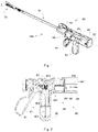
- Fig. 1 is a schematic structural view of an example of a surgical instrument 100.
- the embodiment as shown is an endoscopic instrument.
- the example of the surgical instrument 100 described herein is an endoscopic surgical cutting and stapling instrument.
- the surgical instrument may also be a non-endoscopic surgical cutting and stapling instrument, such as an open surgical instrument for open surgery.
- the surgical instrument 100 shown in Fig. 1 comprises a handle assembly 80, an elongated body 10, and an end effector 70, wherein the elongated body 10 extends distally from the handle assembly 80, and the end effector 70 is assembled on a distal portion of the elongated body 10, in which the end effector 70 is adapted to perform specific surgical operations, such as clamping, suturing/stapling, cutting, etc. on tissues.
- the handle assembly 80 comprises a trigger 81 and a grip portion 82. When the trigger 81 is pulled towards the gripping portion 82, jaws of the end effector 70 may be closed.
- the trigger 81 may also be configured to control the output of a power supplier of the surgical instrument 100.
- one of the embodiments of the surgical instrument 100 described herein is configured with an end effector 70 for cutting anastomosing tissue
- other technologies for cutting or anastomosing tissue may also be used.
- end effectors that applies RF energy or adhesives to anastomose tissues may also be used.
- the surgical instrument 100 further comprises a rotating knob 86 assembled on the distal portion of the handle assembly 80 and fixed with the proximal portion of the elongated body 10.
- the rotating knob 86 is operated to rotate about a longitudinal axis C of the surgical instrument 100, the elongated body 10 and the end effector 70 are rotated accordingly.
- the surgical instrument 100 according to the one of embodiments of the present disclosure further comprises a articulation knob 87, which is rotatably mounted on the rotating knob 86, adapted e for articulating the end effector 70 when being operated.
- Fig. 2 shows an internal structure of the handle assembly 80 of the surgical instrument 100 provided by one of the embodiments.
- the power supplier 85 is arranged in a housing 83, providing power for the surgical instrument 100.
- a control device 853 is also disposed inside housing 83 to control the output of the power supplier 85 to output power, and the control device 853 may be a control circuit board.
- the power supplier 85 used for the surgical instrument 100 may be a motor of any form, as long as it may meet the specific output form and requirements of the surgical instrument 100.
- the power supplier 85 of the surgical instrument 100 in this embodiment adopts a DC brush motor, and the functions of electric firing (forward) and electric retreat of the surgical instrument 100 may be achieved through the forward and reverse rotation of the motor.
- the power supplier 85 may also adopt other types of motors such as a DC brushless motor.
- the handle assembly 80 also comprises an actuation mechanism 89 that comprises a gear assembly 891, a rack assembly 892, and a drive rod.
- the gear assembly 891 is connected to an output of the power supplier 85 and the rack assembly 892 respectively, and a distal portion of the drive rod is arranged in the elongated body 10, and a proximal portion of the drive rod is coupled with the rack assembly 892.
- the power supplier 85 is further provided with a gear box 852, and the motor 851 is coupled to the gear assembly 891 through the gear box 852 so as to provide power for the surgical instrument 100.
- the handle assembly 80 of the surgical instrument 100 may allow at least one battery pack 50 to be received therein.
- a battery dock 88 for receiving the battery pack 50 is arranged on the handle assembly 80.
- the battery pack 50 is detachably assembled in the battery dock 88.
- the battery pack 50 may include a single battery or a plurality of batteries arranged in a series and/or parallel configuration.
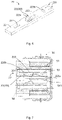
- Fig. 3 and Fig. 4 show the specific structure of the battery pack 50, comprising at least one battery unit 53 and a mounting body adapted for receiving the battery unit 53. As shown in Fig. 3 and Fig.
- the mounting body comprises a housing 51, a frame 54 and a cover 52; the housing 51 is sleeved on an outside of the frame 54, and the battery unit 53 is assembled on the frame 54.
- a plurality of battery units 53 may be arranged in series and/or in parallel configuration. For example, when there are two or more battery units 53, the battery units 53 are connected by conductors 55, such that the plurality of battery units 53 are connected in series. In this embodiment, there are four battery units 53 connected in series. Two battery units 53 at two ends of the series are respectively provided with output terminals 533.
- the cover 52 is provided with an aperture 532 allowing the output terminal 533 to pass through.
- a conductive terminal 854 disposed on the control device 853 is operatively in electrical connection to the output terminal 533 of the battery pack 50, as shown in Fig. 2 and Fig. 5 , so as to provide power to the surgical instrument 100.
- a base assembly 84 is fixed or detachably arranged in the battery dock 88. When the battery pack 50 is assembled and received within the battery dock 88, at least part of the base assembly 84 is coupled to the battery pack 50. In other embodiments, a variety of other structures may be used to achieve functions of the base assembly 84.
- the base assembly 84 comprises a protruding portion 841 that is operably received by the battery pack 50.
- a recess 541 is arranged in the frame 54 of the mounting body of the battery pack 50, which is adapted for receiving the protruding portion 841 of the base assembly 84.
- the protruding portion 841 is arranged perpendicular to the base assembly 84 and is located in a center of the battery base to facilitate insertion into the recess 541 of the frame 54 of the battery pack 50.
- the housing 51 of the battery pack 50 is also provided with a mounting member 511, and a fixing protrusion 512 is arranged on the mounting member 511.
- the battery pack 50 is detachably mounted in the battery dock 88 of the handle assembly 80 through the mounting member 511, the fixing protrusion 512 is adapted for fixing a relative position of the battery pack 50 and the battery dock 88.
- the battery pack 50 of one of the embodiments of the present disclosure further comprises a discharging system 20, adapted for conducting discharging of the battery pack 50, releasing the power of the battery units 53 of the battery pack 50 down to a safe threshold.
- the discharging system 20 comprises a switching member 22 and a discharge element 21 disposed on the discharging circuit board 23.
- the discharge element 21 may be a resistance element, and the resistance element may be any suitable resistance element having any suitable resistance and/or impedance.
- a terminal 531 is further disposed on the discharging circuit board 23 (for example, as shown in Fig. 6 and Fig.
- the switching member 22 has an initial open state, an intermediate open state, and a closed state. For example, when the switching member 22 is in the initial open state or the intermediate open state, the discharging element 21 is not electrically connected to the battery unit 53; when the switching member 22 is in the closed state, the discharging element 21 is electrically connected to the battery unit 53 of the battery pack 50.
- Fig. 5 shows part of the circuit principle of the battery unit 53, the discharging system 20 and the control device 853 in the battery pack 50.
- the switching member 22 When the battery pack 50 is in the initial unused state, the switching member 22 is positioned in the initial open state, and the discharge circuit is not conductive, forming the first state of the discharging system 20; and after the battery pack 50 is assembled in the handle assembly 80 of the surgical instrument 100, the switching member 22 is still operated in the open state, that is to say, the intermediate open state, and the discharge circuit is non-conductive, forming a second state of the discharging system 20; after the battery pack 50 is used, being detached from the surgical instrument 100, the switching member 22 is operated to switch to the turn-on state, and the discharge circuit is conducted, forming a third state of the discharging system 20. When the battery pack 50 has been fully discharged, it may be treated as non-hazardous waste.
- the structure of the discharging system 20 will be described in detail with reference to specific embodiments hereafter.
- Figs. 6 to 12 show a specific example of a battery pack 50 and a discharging system 20 thereof provided by the present disclosure, where the discharging system 20 comprises a switching member 22, one end of which is fixed to the discharging circuit board 23, being electrically connected to the discharge element 21.
- the switching member 22 has an initial open state, an intermediate open state that may be operated, and a closed state, which correspond to the first state, the second state, and the third state of the discharging system 20, respectively.
- the discharging system 20 of one of the embodiments will be described with reference to specific structures.
- the discharging circuit board 23 is disposed on a side wall of the recess 541 of the frame 54 of the battery pack 50. It should be understood that the discharging circuit board 23 may also be arranged on other places of the battery pack 50 for convenient operation.
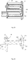
- the switching member 22 is specifically configured as a movable member that is conductive, at least part of the movable member may be operated to move, and at least part of the movable member may be an elastic part, and specifically may be an elastic piece 220, as shown in Fig. 6 and Fig. 7 , an aperture 233 is disposed in the discharging circuit board 23, and at least part of the elastic piece 220 is disposed in the aperture 233.
- the elastic piece 220 comprises a fixed portion 220b which is fixed in the discharging circuit board 23 and in electrical connection with the discharge element 21; a movable portion 220a operably to be connected to the discharging circuit board 23, and operably to be electrically connected to the discharge element 21; and a transition portion 220c which formed between the fixed portion 220b and the movable portion 220a (as shown in Fig. 11 ).
- the movable portion 220a of the elastic piece 220 may be operated to change the position thereof, such that the switching member 22 may be operated to switch between the initial open state, the intermediate open state, and the closed state.
- the switching member 22 when the battery pack 50 is in the initial unused state, the switching member 22 is positioned in the initial open state, i.e. the movable portion 220a of the elastic piece 220 bias against the proximal wall of the aperture 233 of the discharging circuit board 23, as shown in Fig. 7 , where the movable portion 220a of the elastic piece 220 is not in electrical communication with the discharge element 21, the discharge circuit is not conducting, which forms the first state of the discharging system 20.
- the protruding portion 841 When the battery pack 50 is assembled in the battery dock 88 of the surgical instrument 100, the protruding portion 841 is inserted into the recess 541 along an extending direction of the recess 541, and the switching member 22 is operated to be switched to the intermediate open state, i.e., a transition portion 220c of the elastic piece 220 is actuated by the protruding portion 841 so as to drive the movable portion 220a to pass through the aperture 233 along the proximal wall thereof, and the movable portion 220a is biased by the protruding portion 841 so as to be disconnected with the discharging circuit board 23, such that the switching member 22 is maintained to be positioned in the intermediate open state, and where the discharge circuit is non-conductive, forming the second state of the discharging system 20, as shown in Fig.
- the aperture 233 provides space, allowing at least part of the switching member 22 to move, such that at least part of the switching member 22 may be operated to move therein, and to be pass through as well. Therefore, the aperture 233 may also be configured in other shapes, such as a groove, a special-shaped groove, a special-shaped hole, etc..
- the battery pack 50 is removed from the surgical instrument 100, and the protruding portion 841 is removed from the recess 541 as well.
- the movable member 220a of the elastic piece 220 is moved towards the discharging circuit board 23 and contacted with the discharging circuit board 23, so as to be further electrically connected with the discharge element 21, such that, the switching member 22 is switched in the closed state, and the discharge circuit is conducting, forming the third state of the discharging system 20, as shown in Fig. 9 .
- the protruding portion 841 may also be arranged on the base assembly 84 or the grip portion of the handle assembly 80.
- a guide surface may be arranged on the movable portion 220a of the elastic piece 220.
- the guide surface has a guiding effect for the smooth position transition of the movable portion 220a, which is convenient for the movable member 220a to enter the aperture 233 smoothly.
- the battery pack 50 may comprise at least one discharging systems 20 described in one of the embodiments.
- one discharging circuit board 23 may be arranged on the side wall of the recess 541, as shown in Fig. 10 , or two discharge circuit boards 23 may be arranged on the side walls of the recess 541 in a symmetrical or asymmetric manner, as shown in Fig.s 7-9 , other arrangement may be set, and specifically, the discharge circuit board may also be arranged on a proximal side of the recess 541.
- a discharge speed of the battery pack 20 may be increased for rapidly discharging by using a plurality of discharging systems 20 to discharge simultaneously.
- Fig. 11 shows a specific structure of the elastic piece 220.
- the elastic piece 220 comprises a fixed portion 220b and a movable portion 220a, and a transition portion 220c arranged therebetween.
- a certain angle is formed by the fixed portion 220b and the transition portion 220c.
- the fixed portion 220b may be arranged perpendicular to the transition portion 220c;
- the movable portion 220a and the transition portion 220c are also arranged with a certain angle, for example, an acute angle is formed between the movable portion 220a and the transition portion 220c, facilitating the elastic piece 220 to be moved to the corresponding position.
- the movable portion 220a and the transition portion 220c of the elastic piece 220 may also be arranged in other manners for easy to be operated.
- the transition portion 620c of the elastic piece 620 comprises a bent portion 620d.
- Such arrangement of the bent portion 620c weakens the rigidity of the transition portion 620c, which makes it easier for the elastic piece 620 to be operated to move, such that bias force applied during operation is reduced.
- the transition portion of the elastic piece in this embodiment may also be designed into other structures with weakening effect.
- Figs. 13 to 19 show the specific structures of the surgical instrument 100, the battery pack 50 and the discharging system 20 in an alternative embodiment of the present disclosure, in which the switching member 22 of the discharging system 20 is arranged at a proximal side of the recess 541 of the frame of the battery pack 50, or the switching member 22 may also be arranged in other ways, for example, it may also be arranged on the side wall of the recess 541 to be electrically connected to the discharge element 21, and the discharging circuit board 23 may be arranged between the frame 54 and the housing 51.
- the switching member 22 of the discharging system 20 comprises a blocking member 221 and a conductive member.
- the conductive member comprises at least two separable conductive elastic members, i.e. conductive elastic pieces 222.
- One end of each conductive elastic piece 222 is a fixed end fixed on the discharging circuit board 23 and electrically connected to the discharge element 21.
- the other end of each the conductive elastic piece 222 is a free end.
- the blocking member 221 is arranged between the free ends of at least two conductive elastic pieces 222 to operably separate the conductive elastic pieces 222 from each other, preventing the conductive member being electrical conducting.
- the function of the blocking member described in one of the embodiments of the present disclosure is to make the switching structure 22 being positioned in the initial open state, where, the discharge circuit is non-conductive, and the blocking member may be operated to be functionally disabled for blocking and the switching member is switched into the intermediate open state.
- blocking may be either a physical blocking or an electrical blocking, as long as it may keep the switching member in the initial open state.
- the blocking member 221 of the discharging system 20 is biasing free ends of the conductive elastic pieces 222 to be separated from each other, preventing the conductive member from being electrical conducting, and the switching member 22 is positioned in the initial open state, while the discharging system 20 is in the first state.
- the protruding portion 842 is inserted into the recess 541 along an extending direction of the recess 541, and abuts against the blocking member 221.
- the blocking member 221 is actuated by the proximal end of the protruding portion 842 and released from the conductive elastic piece 222.
- the conductive elastic pieces 222 are remained to be isolated from each other through the proximal end of the protruding portion 842, preventing the conductive member to be electrical conductive, where the switching member 22 is remained in the open state, i.e., the intermediate open state, and the discharging system 20 is in the second state.
- the battery pack 50 is removed from the surgical instrument 100, and the protruding portion 842 is removed from the recess 541 as well as the conductive elastic pieces 222 of the conductive member, where, as shown in Fig. 16 , the conductive elastic pieces 222 contact with each other so as to be conductive, the switching member 22 is switched to the closed state, and the discharging system 20 comes to the third state, the discharging element 21 and the battery unit 53 are conducting, and the battery unit 53 starts to be discharged.
- the protruding portion 842 may be arranged on the base assembly 84 or the grip part of the handle assembly.
- Fig. 17 shows the specific structure of the conductive elastic piece 222 which comprises an elastic body 222a having a first end (i.e. a fixed end) connected to the discharging circuit board 23, and a second end having a bended portion 222b which extends toward the other conductive elastic piece 222 arranged on the opposite side thereof, inclining towards the first end in the extending direction, so as to be convenient for locating the blocking member 221.
- the blocking member 221 is arranged between the two bended portions 222b when the discharging system 20 is in the first state.
- the conductive elastic piece 222 also comprises a fitting portion 222c disposed on the bended portion 222b.
- the fitting portion 222c is arranged such that a line contact formed by the two oppositely disposed bended portions locating the blocking member 221 turns to a face contact, which leads to an increased contact area between the conductive elastic piece 222 and the blocking member 221, providing more stable location, so as to prevent the blocking member 221 from falling during transportation.
- Fig. 18 shows the specific structure of the blocking member 221.
- the blocking member 221 has a columnar structure and has a slope surface inclined towards a center line of the columnar structure; the blocking member 221 is configured to have this shape, such that when the blocking member 221 is located between two conductive elastic pieces 222, it is convenient for the amounting of the blocking member 221; where, it also facilitates the protruding portion 842 to push the blocking member 221 to be released from arrangement between the two conductive elastic pieces 222. Since the blocking member 221 is adapted for to isolate the conductive elastic pieces 222, the blocking member 221 is configured as an insulating member.
- Figs. 20 to 24 show an alternative embodiment of the battery pack 50 and the discharging system 20 of the present disclosure.
- the switching member 22 of the discharging system 20 comprises a blocking member and a conductive member, and the blocking member is specifically configured as a first switch 321, the conductive member is specifically configured as a second switch 322 and the first switch 321 and the second switch 322 are both arranged on the discharging circuit board 23.
- a protruding portion is arranged on the base assembly 84, provided with a fin portion 843 which is adapted to operably cooperate with the first switch 321 and/or the second switch 322.
- the protruding portion may be arranged on the base assembly 84 or the grip part of the handle assembly.
- the first switch 321 remains switched off, and the second switch 322 is not conducting, where the switching member 22 is in the initial open state, and the discharging system 20 is in the first state.
- the protruding portion and the fin portion 843 are inserted into the recess 541 along an extending direction of the recess 541.
- the fin portion 843 interacts with the first switch 321 such that the switch 321 is conducting, while the second switch remains in the turn-off state due to the engagement of the fin portion 843, i.e., the conductive member remains in a non-conductive state, where the switching member 22 is in the intermediate open state, and the discharging system 20 is in the second state.
- the battery pack 50 is removed from the surgical instrument 100, and the protruding portion and the fin portion 843 are operated to be removed out of the recess 541 as well, where the second switch 322 is switched to be conductive without the engagement with the fin portion 843, such that the switching member 22 is switched to the closed state, and the discharging system 20 is switched to the third state, where the discharging element 21 and the battery unit 53 are conducting, and the battery unit 53 starts to be discharged.
- the first switch 321 described in this embodiment is a self-locking switch, allowing the first switch remains in the previous state, i.e., a conducting state, after being disengaged with the fin portion 843.
- the second switch 322 described in this embodiment is preferably an electronic switch, such as a photoelectric switch, which is composed of a light emitting end and a light receiving end. When the discharging system 20 is in the second state, the photoelectric switch remains in a non-conductive state due to the blocking of the fin portion 843.
- the photoelectric switch As the fin portion 843 is removed from the recess 541, the photoelectric switch is no longer blocked, and a connection may be established between the transmitting end and the receiving end, so that the photoelectric switch is conducting, and the discharging system 20 is switched to the third state, thereby self-discharge function of the battery unit 53 of the battery pack 50 is realized.
- the arrangement of the fin portion 843 may be set according to the positions of the first switch 321 and the second switch 322.
- the first switch 321 and the second switch 322 may also be selected from other suitable switching elements, as long as they may comply with the above functional principles.
- Figs. 25 to 29 show still another embodiment of the battery pack 50 and its discharging system 20 described in the present disclosure.
- the conductive member of the switching member 22 of the discharging system 20 is configured as a normal-close switch 421, and the blocking member is a stop member.
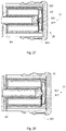
- the stop member is configured as a limit plate 422, and the limit plate 422 is configured to abut against the normal-close switch 421, such that the switch 421 is in initial switched-off (open) state, as shown in Fig. 26 .
- a tip is arranged on a proximal end of the protruding portion 844 of this embodiment, which is adapted to operably break the limit plate 422, such that the limit plate 422 capable of maintaining the normal-close switch 421 in the switched-off state without blocking.
- the stop member 422 may be made of a brittle sheet material that is easy to be broken by operation, or the stop member 422 may be provided with indentations to facilitate the breaking by operation thereof.
- the limit plate 422 abuts against the normal-close switch 421, forcing it in the switched-off state, where, the switching member 22 is in the initial open state, and the discharging system 20 is in the first state.
- the protruding portion 844 and the tip are inserted into the recess 541 along the extending direction of the recess 541, and the tip is in contact with the stop member 422 and causes it to break.
- the normal-close switch 421 is remained in the switched off state due to engagement with the protruding portion 844, i.e., the conductive member remains in the non-conductive state, where, the switching member 22 is in the intermediate open state, and the discharging system 20 is in the second state.
- the battery pack 50 is removed from the surgical instrument 100, and the protruding portion 844 and the tip are removed from the recess 541 as well, where the normal-close switch 421 is conducting due to being disengaged with the limit plate 422, and the switching member 22 is switched to the closed state, the discharging system 20 is switched to the third state, where the discharging element 21, the battery unit 53 are conducting, and the battery unit 53 starts to be discharged.
- the normal-close switch described in this embodiment refers to a switch in the closed state without external force.
- the switch button When a switch button is toggled or the switch is controlled by an automatic device to toggle, the switch is switched to an open circuit.
- the normal-close switch may be a travel switch, a pressure relay, etc..
- the arrangement of the tip of the protruding portion 844 may be made according to the shape of the normal-closed switch 421 on its own, and the protruding portion 844 may be arranged on the base assembly 84 or the grip part of the handle assembly.
- the position of the limit plate 422 may also be set according to the switched off position of the normal-close switch 421, as long as it may meet the above functional principle.
Landscapes
- Engineering & Computer Science (AREA)
- General Chemical & Material Sciences (AREA)
- Chemical & Material Sciences (AREA)
- Chemical Kinetics & Catalysis (AREA)
- Electrochemistry (AREA)
- Health & Medical Sciences (AREA)
- Life Sciences & Earth Sciences (AREA)
- Surgery (AREA)
- Power Engineering (AREA)
- Animal Behavior & Ethology (AREA)
- General Health & Medical Sciences (AREA)
- Biomedical Technology (AREA)
- Heart & Thoracic Surgery (AREA)
- Medical Informatics (AREA)
- Molecular Biology (AREA)
- Manufacturing & Machinery (AREA)
- Nuclear Medicine, Radiotherapy & Molecular Imaging (AREA)
- Public Health (AREA)
- Veterinary Medicine (AREA)
- Biophysics (AREA)
- Computer Hardware Design (AREA)
- Microelectronics & Electronic Packaging (AREA)
- Battery Mounting, Suspending (AREA)
Applications Claiming Priority (1)
| Application Number | Priority Date | Filing Date | Title |
|---|---|---|---|
| PCT/CN2020/115563 WO2022056720A1 (fr) | 2020-09-16 | 2020-09-16 | Instrument chirurgical et son bloc-batterie |
Publications (4)
| Publication Number | Publication Date |
|---|---|
| EP4018938A1 true EP4018938A1 (fr) | 2022-06-29 |
| EP4018938A4 EP4018938A4 (fr) | 2022-11-02 |
| EP4018938B1 EP4018938B1 (fr) | 2023-12-27 |
| EP4018938C0 EP4018938C0 (fr) | 2023-12-27 |
Family
ID=74123615
Family Applications (1)
| Application Number | Title | Priority Date | Filing Date |
|---|---|---|---|
| EP20953500.4A Active EP4018938B1 (fr) | 2020-09-16 | 2020-09-16 | Instrument chirurgical avec bloc-batterie |
Country Status (5)
| Country | Link |
|---|---|
| US (1) | US11950780B2 (fr) |
| EP (1) | EP4018938B1 (fr) |
| CN (3) | CN112236090B (fr) |
| ES (1) | ES2968001T3 (fr) |
| WO (1) | WO2022056720A1 (fr) |
Families Citing this family (6)
| Publication number | Priority date | Publication date | Assignee | Title |
|---|---|---|---|---|
| US11937794B2 (en) * | 2020-05-11 | 2024-03-26 | Covidien Lp | Powered handle assembly for surgical devices |
| CN116073056A (zh) * | 2021-10-29 | 2023-05-05 | 宁波海泰科迈医疗器械有限公司 | 用于电动医疗器械的电池组件以及电动医疗器械 |
| US20250329803A1 (en) * | 2022-05-12 | 2025-10-23 | Covidien Lp | Battery discharge mechanism for surgical instruments |
| CN115300022B (zh) * | 2022-08-26 | 2025-08-19 | 苏州贝诺医疗器械有限公司 | 一种一次性电源控制的保护性电动吻合器 |
| CN116269582B (zh) | 2023-05-19 | 2023-11-07 | 上海逸思医疗科技股份有限公司 | 一种外科器械及其组装方法 |
| WO2026025784A1 (fr) * | 2024-07-29 | 2026-02-05 | 广东博迈医疗科技股份有限公司 | Ensemble compartiment de batterie à autoconsommation et dispositif médical |
Family Cites Families (26)
| Publication number | Priority date | Publication date | Assignee | Title |
|---|---|---|---|---|
| US4986369A (en) * | 1988-07-11 | 1991-01-22 | Makita Electric Works, Ltd. | Torque adjusting mechanism for power driven rotary tools |
| US5207697A (en) * | 1991-06-27 | 1993-05-04 | Stryker Corporation | Battery powered surgical handpiece |
| US11229472B2 (en) * | 2001-06-12 | 2022-01-25 | Cilag Gmbh International | Modular battery powered handheld surgical instrument with multiple magnetic position sensors |
| US7589500B2 (en) * | 2002-11-22 | 2009-09-15 | Milwaukee Electric Tool Corporation | Method and system for battery protection |
| US7714538B2 (en) * | 2002-11-22 | 2010-05-11 | Milwaukee Electric Tool Corporation | Battery pack |
| JP5316831B2 (ja) * | 2006-02-28 | 2013-10-16 | 日立工機株式会社 | コードレス電動工具または充電器 |
| US20110022032A1 (en) * | 2007-10-05 | 2011-01-27 | Tyco Healthcare Group Lp | Battery ejection design for a surgical device |
| US20090143800A1 (en) * | 2007-12-03 | 2009-06-04 | Derek Dee Deville | Cordless Hand-Held Ultrasonic Cautery Cutting Device |
| US9017355B2 (en) * | 2007-12-03 | 2015-04-28 | Covidien Ag | Battery-powered hand-held ultrasonic surgical cautery cutting device |
| US9314261B2 (en) * | 2007-12-03 | 2016-04-19 | Covidien Ag | Battery-powered hand-held ultrasonic surgical cautery cutting device |
| US20230138097A1 (en) * | 2009-01-29 | 2023-05-04 | Peter Forsell | Stomach instrument and method |
| US8632525B2 (en) * | 2010-09-17 | 2014-01-21 | Ethicon Endo-Surgery, Inc. | Power control arrangements for surgical instruments and batteries |
| US9289212B2 (en) * | 2010-09-17 | 2016-03-22 | Ethicon Endo-Surgery, Inc. | Surgical instruments and batteries for surgical instruments |
| CA3022252C (fr) * | 2011-04-15 | 2020-09-22 | Covidien Ag | Cautere ultrasonique a main alimente par pile |
| US8981724B2 (en) * | 2013-03-14 | 2015-03-17 | Lg Chem, Ltd. | Battery pack discharging device and method for discharging a battery pack |
| US10159483B2 (en) * | 2015-02-27 | 2018-12-25 | Ethicon Llc | Surgical apparatus configured to track an end-of-life parameter |
| US10194911B2 (en) * | 2015-06-26 | 2019-02-05 | Ethicon Llc | Surgical stapler with ready state indicator |
| US10314578B2 (en) * | 2015-09-29 | 2019-06-11 | Ethicon Llc | Battery drain circuit for surgical instrument |
| CN206026379U (zh) * | 2016-07-01 | 2017-03-22 | 北京派尔特医疗科技股份有限公司 | 吻合器控制电路及电动吻合器 |
| EP3566259B1 (fr) * | 2017-01-09 | 2023-03-08 | Milwaukee Electric Tool Corporation | Bloc-batterie |
| CN208130022U (zh) * | 2017-04-28 | 2018-11-23 | 北京派尔特医疗科技股份有限公司 | 电动腔镜吻合器的电源控制系统 |
| US10987103B2 (en) * | 2017-06-27 | 2021-04-27 | Ethicon Llc | Powered surgical instrument with latching feature preventing removal of battery pack |
| CA3181599A1 (fr) * | 2017-07-24 | 2019-01-31 | Koki Holdings Co., Ltd. | Bloc-batterie et dispositif electrique utilisant un bloc-batterie |
| US10695060B2 (en) * | 2017-09-01 | 2020-06-30 | RevMedica, Inc. | Loadable power pack for surgical instruments |
| CN110137731A (zh) * | 2019-05-24 | 2019-08-16 | 业成科技(成都)有限公司 | 电连接器 |
| CN110974329A (zh) * | 2019-11-13 | 2020-04-10 | 北京派尔特医疗科技股份有限公司 | 吻合器及其计时放电方法 |
-
2020
- 2020-09-16 EP EP20953500.4A patent/EP4018938B1/fr active Active
- 2020-09-16 ES ES20953500T patent/ES2968001T3/es active Active
- 2020-09-16 CN CN202080002034.8A patent/CN112236090B/zh active Active
- 2020-09-16 WO PCT/CN2020/115563 patent/WO2022056720A1/fr not_active Ceased
- 2020-09-16 CN CN202310105088.2A patent/CN116019516A/zh active Pending
- 2020-09-16 CN CN202310101402.XA patent/CN116172636B/zh active Active
-
2022
- 2022-03-22 US US17/655,819 patent/US11950780B2/en active Active
Also Published As
| Publication number | Publication date |
|---|---|
| US20220211373A1 (en) | 2022-07-07 |
| CN112236090A (zh) | 2021-01-15 |
| EP4018938B1 (fr) | 2023-12-27 |
| WO2022056720A1 (fr) | 2022-03-24 |
| ES2968001T3 (es) | 2024-05-06 |
| CN116019516A (zh) | 2023-04-28 |
| EP4018938A4 (fr) | 2022-11-02 |
| US11950780B2 (en) | 2024-04-09 |
| CN116172636A (zh) | 2023-05-30 |
| EP4018938C0 (fr) | 2023-12-27 |
| CN112236090B (zh) | 2023-03-31 |
| CN116172636B (zh) | 2025-09-26 |
Similar Documents
| Publication | Publication Date | Title |
|---|---|---|
| US11950780B2 (en) | Surgical instrument and battery pack thereof | |
| US12440213B2 (en) | Surgical instrument having a power control circuit | |
| US20240293123A1 (en) | Surgical instrument battery comprising a plurality of cells | |
| US8453914B2 (en) | Motor-driven surgical cutting instrument with electric actuator directional control assembly | |
| RU2714684C1 (ru) | Электрическая схема для разряда аккумуляторной батареи для хирургического инструмента | |
| CN216085162U (zh) | 用于电动医疗器械的电池组件以及电动医疗器械 | |
| CN219203412U (zh) | 一种外科器械的电池组及其外科器械 | |
| US20250329803A1 (en) | Battery discharge mechanism for surgical instruments | |
| WO2005020834A2 (fr) | Instrument de coagulation |
Legal Events
| Date | Code | Title | Description |
|---|---|---|---|
| STAA | Information on the status of an ep patent application or granted ep patent |
Free format text: STATUS: UNKNOWN |
|
| STAA | Information on the status of an ep patent application or granted ep patent |
Free format text: STATUS: THE INTERNATIONAL PUBLICATION HAS BEEN MADE |
|
| PUAI | Public reference made under article 153(3) epc to a published international application that has entered the european phase |
Free format text: ORIGINAL CODE: 0009012 |
|
| STAA | Information on the status of an ep patent application or granted ep patent |
Free format text: STATUS: REQUEST FOR EXAMINATION WAS MADE |
|
| 17P | Request for examination filed |
Effective date: 20220322 |
|
| AK | Designated contracting states |
Kind code of ref document: A1 Designated state(s): AL AT BE BG CH CY CZ DE DK EE ES FI FR GB GR HR HU IE IS IT LI LT LU LV MC MK MT NL NO PL PT RO RS SE SI SK SM TR |
|
| A4 | Supplementary search report drawn up and despatched |
Effective date: 20221005 |
|
| RIC1 | Information provided on ipc code assigned before grant |
Ipc: A61B 17/00 20060101ALN20220928BHEP Ipc: H02J 7/00 20060101ALI20220928BHEP Ipc: A61B 17/072 20060101AFI20220928BHEP |
|
| DAV | Request for validation of the european patent (deleted) | ||
| DAX | Request for extension of the european patent (deleted) | ||
| STAA | Information on the status of an ep patent application or granted ep patent |
Free format text: STATUS: EXAMINATION IS IN PROGRESS |
|
| 17Q | First examination report despatched |
Effective date: 20230323 |
|
| P01 | Opt-out of the competence of the unified patent court (upc) registered |
Effective date: 20230523 |
|
| RIC1 | Information provided on ipc code assigned before grant |
Ipc: A61B 17/00 20060101ALN20230911BHEP Ipc: H01M 50/284 20210101ALI20230911BHEP Ipc: H01M 50/269 20210101ALI20230911BHEP Ipc: H01M 50/247 20210101ALI20230911BHEP Ipc: H01M 50/213 20210101ALI20230911BHEP Ipc: H01M 10/44 20060101ALI20230911BHEP Ipc: H01M 10/42 20060101ALI20230911BHEP Ipc: A61B 17/072 20060101AFI20230911BHEP |
|
| GRAP | Despatch of communication of intention to grant a patent |
Free format text: ORIGINAL CODE: EPIDOSNIGR1 |
|
| STAA | Information on the status of an ep patent application or granted ep patent |
Free format text: STATUS: GRANT OF PATENT IS INTENDED |
|
| RIC1 | Information provided on ipc code assigned before grant |
Ipc: A61B 17/00 20060101ALN20230925BHEP Ipc: H01M 50/284 20210101ALI20230925BHEP Ipc: H01M 50/269 20210101ALI20230925BHEP Ipc: H01M 50/247 20210101ALI20230925BHEP Ipc: H01M 50/213 20210101ALI20230925BHEP Ipc: H01M 10/44 20060101ALI20230925BHEP Ipc: H01M 10/42 20060101ALI20230925BHEP Ipc: A61B 17/072 20060101AFI20230925BHEP |
|
| GRAS | Grant fee paid |
Free format text: ORIGINAL CODE: EPIDOSNIGR3 |
|
| INTG | Intention to grant announced |
Effective date: 20231024 |
|
| RIC1 | Information provided on ipc code assigned before grant |
Ipc: A61B 17/00 20060101ALN20231016BHEP Ipc: H01M 50/284 20210101ALI20231016BHEP Ipc: H01M 50/269 20210101ALI20231016BHEP Ipc: H01M 50/247 20210101ALI20231016BHEP Ipc: H01M 50/213 20210101ALI20231016BHEP Ipc: H01M 10/44 20060101ALI20231016BHEP Ipc: H01M 10/42 20060101ALI20231016BHEP Ipc: A61B 17/072 20060101AFI20231016BHEP |
|
| GRAA | (expected) grant |
Free format text: ORIGINAL CODE: 0009210 |
|
| STAA | Information on the status of an ep patent application or granted ep patent |
Free format text: STATUS: THE PATENT HAS BEEN GRANTED |
|
| AK | Designated contracting states |
Kind code of ref document: B1 Designated state(s): AL AT BE BG CH CY CZ DE DK EE ES FI FR GB GR HR HU IE IS IT LI LT LU LV MC MK MT NL NO PL PT RO RS SE SI SK SM TR |
|
| REG | Reference to a national code |
Ref country code: GB Ref legal event code: FG4D |
|
| REG | Reference to a national code |
Ref country code: CH Ref legal event code: EP |
|
| REG | Reference to a national code |
Ref country code: DE Ref legal event code: R096 Ref document number: 602020023632 Country of ref document: DE |
|
| REG | Reference to a national code |
Ref country code: IE Ref legal event code: FG4D |
|
| U01 | Request for unitary effect filed |
Effective date: 20240108 |
|
| U07 | Unitary effect registered |
Designated state(s): AT BE BG DE DK EE FI FR IT LT LU LV MT NL PT SE SI Effective date: 20240116 |
|
| P04 | Withdrawal of opt-out of the competence of the unified patent court (upc) registered |
Effective date: 20240112 |
|
| PG25 | Lapsed in a contracting state [announced via postgrant information from national office to epo] |
Ref country code: GR Free format text: LAPSE BECAUSE OF FAILURE TO SUBMIT A TRANSLATION OF THE DESCRIPTION OR TO PAY THE FEE WITHIN THE PRESCRIBED TIME-LIMIT Effective date: 20240328 |
|
| PG25 | Lapsed in a contracting state [announced via postgrant information from national office to epo] |
Ref country code: GR Free format text: LAPSE BECAUSE OF FAILURE TO SUBMIT A TRANSLATION OF THE DESCRIPTION OR TO PAY THE FEE WITHIN THE PRESCRIBED TIME-LIMIT Effective date: 20240328 |
|
| REG | Reference to a national code |
Ref country code: ES Ref legal event code: FG2A Ref document number: 2968001 Country of ref document: ES Kind code of ref document: T3 Effective date: 20240506 |
|
| PG25 | Lapsed in a contracting state [announced via postgrant information from national office to epo] |
Ref country code: RS Free format text: LAPSE BECAUSE OF FAILURE TO SUBMIT A TRANSLATION OF THE DESCRIPTION OR TO PAY THE FEE WITHIN THE PRESCRIBED TIME-LIMIT Effective date: 20231227 Ref country code: NO Free format text: LAPSE BECAUSE OF FAILURE TO SUBMIT A TRANSLATION OF THE DESCRIPTION OR TO PAY THE FEE WITHIN THE PRESCRIBED TIME-LIMIT Effective date: 20240327 Ref country code: HR Free format text: LAPSE BECAUSE OF FAILURE TO SUBMIT A TRANSLATION OF THE DESCRIPTION OR TO PAY THE FEE WITHIN THE PRESCRIBED TIME-LIMIT Effective date: 20231227 |
|
| PG25 | Lapsed in a contracting state [announced via postgrant information from national office to epo] |
Ref country code: IS Free format text: LAPSE BECAUSE OF FAILURE TO SUBMIT A TRANSLATION OF THE DESCRIPTION OR TO PAY THE FEE WITHIN THE PRESCRIBED TIME-LIMIT Effective date: 20240427 |
|
| PG25 | Lapsed in a contracting state [announced via postgrant information from national office to epo] |
Ref country code: CZ Free format text: LAPSE BECAUSE OF FAILURE TO SUBMIT A TRANSLATION OF THE DESCRIPTION OR TO PAY THE FEE WITHIN THE PRESCRIBED TIME-LIMIT Effective date: 20231227 |
|
| PG25 | Lapsed in a contracting state [announced via postgrant information from national office to epo] |
Ref country code: SK Free format text: LAPSE BECAUSE OF FAILURE TO SUBMIT A TRANSLATION OF THE DESCRIPTION OR TO PAY THE FEE WITHIN THE PRESCRIBED TIME-LIMIT Effective date: 20231227 |
|
| PG25 | Lapsed in a contracting state [announced via postgrant information from national office to epo] |
Ref country code: SM Free format text: LAPSE BECAUSE OF FAILURE TO SUBMIT A TRANSLATION OF THE DESCRIPTION OR TO PAY THE FEE WITHIN THE PRESCRIBED TIME-LIMIT Effective date: 20231227 Ref country code: SK Free format text: LAPSE BECAUSE OF FAILURE TO SUBMIT A TRANSLATION OF THE DESCRIPTION OR TO PAY THE FEE WITHIN THE PRESCRIBED TIME-LIMIT Effective date: 20231227 Ref country code: RO Free format text: LAPSE BECAUSE OF FAILURE TO SUBMIT A TRANSLATION OF THE DESCRIPTION OR TO PAY THE FEE WITHIN THE PRESCRIBED TIME-LIMIT Effective date: 20231227 Ref country code: IS Free format text: LAPSE BECAUSE OF FAILURE TO SUBMIT A TRANSLATION OF THE DESCRIPTION OR TO PAY THE FEE WITHIN THE PRESCRIBED TIME-LIMIT Effective date: 20240427 Ref country code: CZ Free format text: LAPSE BECAUSE OF FAILURE TO SUBMIT A TRANSLATION OF THE DESCRIPTION OR TO PAY THE FEE WITHIN THE PRESCRIBED TIME-LIMIT Effective date: 20231227 |
|
| PG25 | Lapsed in a contracting state [announced via postgrant information from national office to epo] |
Ref country code: PL Free format text: LAPSE BECAUSE OF FAILURE TO SUBMIT A TRANSLATION OF THE DESCRIPTION OR TO PAY THE FEE WITHIN THE PRESCRIBED TIME-LIMIT Effective date: 20231227 |
|
| PG25 | Lapsed in a contracting state [announced via postgrant information from national office to epo] |
Ref country code: PL Free format text: LAPSE BECAUSE OF FAILURE TO SUBMIT A TRANSLATION OF THE DESCRIPTION OR TO PAY THE FEE WITHIN THE PRESCRIBED TIME-LIMIT Effective date: 20231227 |
|
| REG | Reference to a national code |
Ref country code: DE Ref legal event code: R097 Ref document number: 602020023632 Country of ref document: DE |
|
| U20 | Renewal fee for the european patent with unitary effect paid |
Year of fee payment: 5 Effective date: 20240925 |
|
| PLBE | No opposition filed within time limit |
Free format text: ORIGINAL CODE: 0009261 |
|
| STAA | Information on the status of an ep patent application or granted ep patent |
Free format text: STATUS: NO OPPOSITION FILED WITHIN TIME LIMIT |
|
| 26N | No opposition filed |
Effective date: 20240930 |
|
| P05 | Withdrawal of opt-out of the competence of the unified patent court (upc) changed |
Free format text: CASE NUMBER: APP_1717/2024 Effective date: 20240116 |
|
| PG25 | Lapsed in a contracting state [announced via postgrant information from national office to epo] |
Ref country code: MC Free format text: LAPSE BECAUSE OF FAILURE TO SUBMIT A TRANSLATION OF THE DESCRIPTION OR TO PAY THE FEE WITHIN THE PRESCRIBED TIME-LIMIT Effective date: 20231227 |
|
| REG | Reference to a national code |
Ref country code: CH Ref legal event code: PL |
|
| PG25 | Lapsed in a contracting state [announced via postgrant information from national office to epo] |
Ref country code: CH Free format text: LAPSE BECAUSE OF NON-PAYMENT OF DUE FEES Effective date: 20240930 |
|
| PG25 | Lapsed in a contracting state [announced via postgrant information from national office to epo] |
Ref country code: IE Free format text: LAPSE BECAUSE OF NON-PAYMENT OF DUE FEES Effective date: 20240916 |
|
| PGFP | Annual fee paid to national office [announced via postgrant information from national office to epo] |
Ref country code: GB Payment date: 20250919 Year of fee payment: 6 |
|
| U20 | Renewal fee for the european patent with unitary effect paid |
Year of fee payment: 6 Effective date: 20250924 |
|
| PG25 | Lapsed in a contracting state [announced via postgrant information from national office to epo] |
Ref country code: CY Free format text: LAPSE BECAUSE OF FAILURE TO SUBMIT A TRANSLATION OF THE DESCRIPTION OR TO PAY THE FEE WITHIN THE PRESCRIBED TIME-LIMIT; INVALID AB INITIO Effective date: 20200916 |
|
| PGFP | Annual fee paid to national office [announced via postgrant information from national office to epo] |
Ref country code: ES Payment date: 20251030 Year of fee payment: 6 |
|
| PG25 | Lapsed in a contracting state [announced via postgrant information from national office to epo] |
Ref country code: HU Free format text: LAPSE BECAUSE OF FAILURE TO SUBMIT A TRANSLATION OF THE DESCRIPTION OR TO PAY THE FEE WITHIN THE PRESCRIBED TIME-LIMIT; INVALID AB INITIO Effective date: 20200916 |