EP4018955A1 - Interface utilisateur graphique pour l'ablation bipolaire - Google Patents
Interface utilisateur graphique pour l'ablation bipolaire Download PDFInfo
- Publication number
- EP4018955A1 EP4018955A1 EP21216312.5A EP21216312A EP4018955A1 EP 4018955 A1 EP4018955 A1 EP 4018955A1 EP 21216312 A EP21216312 A EP 21216312A EP 4018955 A1 EP4018955 A1 EP 4018955A1
- Authority
- EP
- European Patent Office
- Prior art keywords
- electrodes
- widget
- ablation
- selection
- selection status
- Prior art date
- Legal status (The legal status is an assumption and is not a legal conclusion. Google has not performed a legal analysis and makes no representation as to the accuracy of the status listed.)
- Pending
Links
Images




Classifications
-
- A—HUMAN NECESSITIES
- A61—MEDICAL OR VETERINARY SCIENCE; HYGIENE
- A61B—DIAGNOSIS; SURGERY; IDENTIFICATION
- A61B18/00—Surgical instruments, devices or methods for transferring non-mechanical forms of energy to or from the body
- A61B18/04—Surgical instruments, devices or methods for transferring non-mechanical forms of energy to or from the body by heating
- A61B18/12—Surgical instruments, devices or methods for transferring non-mechanical forms of energy to or from the body by heating by passing a current through the tissue to be heated, e.g. high-frequency current
- A61B18/14—Probes or electrodes therefor
- A61B18/1492—Probes or electrodes therefor having a flexible, catheter-like structure, e.g. for heart ablation
-
- A—HUMAN NECESSITIES
- A61—MEDICAL OR VETERINARY SCIENCE; HYGIENE
- A61B—DIAGNOSIS; SURGERY; IDENTIFICATION
- A61B10/00—Instruments for taking body samples for diagnostic purposes; Other methods or instruments for diagnosis, e.g. for vaccination diagnosis, sex determination or ovulation-period determination; Throat striking implements
- A61B10/02—Instruments for taking cell samples or for biopsy
-
- A—HUMAN NECESSITIES
- A61—MEDICAL OR VETERINARY SCIENCE; HYGIENE
- A61B—DIAGNOSIS; SURGERY; IDENTIFICATION
- A61B18/00—Surgical instruments, devices or methods for transferring non-mechanical forms of energy to or from the body
- A61B18/04—Surgical instruments, devices or methods for transferring non-mechanical forms of energy to or from the body by heating
- A61B18/12—Surgical instruments, devices or methods for transferring non-mechanical forms of energy to or from the body by heating by passing a current through the tissue to be heated, e.g. high-frequency current
-
- A—HUMAN NECESSITIES
- A61—MEDICAL OR VETERINARY SCIENCE; HYGIENE
- A61B—DIAGNOSIS; SURGERY; IDENTIFICATION
- A61B18/00—Surgical instruments, devices or methods for transferring non-mechanical forms of energy to or from the body
-
- A—HUMAN NECESSITIES
- A61—MEDICAL OR VETERINARY SCIENCE; HYGIENE
- A61B—DIAGNOSIS; SURGERY; IDENTIFICATION
- A61B34/00—Computer-aided surgery; Manipulators or robots specially adapted for use in surgery
- A61B34/25—User interfaces for surgical systems
-
- A—HUMAN NECESSITIES
- A61—MEDICAL OR VETERINARY SCIENCE; HYGIENE
- A61B—DIAGNOSIS; SURGERY; IDENTIFICATION
- A61B17/00—Surgical instruments, devices or methods
- A61B2017/00017—Electrical control of surgical instruments
- A61B2017/00199—Electrical control of surgical instruments with a console, e.g. a control panel with a display
-
- A—HUMAN NECESSITIES
- A61—MEDICAL OR VETERINARY SCIENCE; HYGIENE
- A61B—DIAGNOSIS; SURGERY; IDENTIFICATION
- A61B18/00—Surgical instruments, devices or methods for transferring non-mechanical forms of energy to or from the body
- A61B2018/00053—Mechanical features of the instrument of device
- A61B2018/0016—Energy applicators arranged in a two- or three dimensional array
-
- A—HUMAN NECESSITIES
- A61—MEDICAL OR VETERINARY SCIENCE; HYGIENE
- A61B—DIAGNOSIS; SURGERY; IDENTIFICATION
- A61B18/00—Surgical instruments, devices or methods for transferring non-mechanical forms of energy to or from the body
- A61B2018/00053—Mechanical features of the instrument of device
- A61B2018/00214—Expandable means emitting energy, e.g. by elements carried thereon
- A61B2018/0022—Balloons
-
- A—HUMAN NECESSITIES
- A61—MEDICAL OR VETERINARY SCIENCE; HYGIENE
- A61B—DIAGNOSIS; SURGERY; IDENTIFICATION
- A61B18/00—Surgical instruments, devices or methods for transferring non-mechanical forms of energy to or from the body
- A61B2018/00053—Mechanical features of the instrument of device
- A61B2018/00214—Expandable means emitting energy, e.g. by elements carried thereon
- A61B2018/00267—Expandable means emitting energy, e.g. by elements carried thereon having a basket shaped structure
-
- A—HUMAN NECESSITIES
- A61—MEDICAL OR VETERINARY SCIENCE; HYGIENE
- A61B—DIAGNOSIS; SURGERY; IDENTIFICATION
- A61B18/00—Surgical instruments, devices or methods for transferring non-mechanical forms of energy to or from the body
- A61B2018/00315—Surgical instruments, devices or methods for transferring non-mechanical forms of energy to or from the body for treatment of particular body parts
- A61B2018/00345—Vascular system
- A61B2018/00351—Heart
-
- A—HUMAN NECESSITIES
- A61—MEDICAL OR VETERINARY SCIENCE; HYGIENE
- A61B—DIAGNOSIS; SURGERY; IDENTIFICATION
- A61B18/00—Surgical instruments, devices or methods for transferring non-mechanical forms of energy to or from the body
- A61B2018/00571—Surgical instruments, devices or methods for transferring non-mechanical forms of energy to or from the body for achieving a particular surgical effect
- A61B2018/00577—Ablation
-
- A—HUMAN NECESSITIES
- A61—MEDICAL OR VETERINARY SCIENCE; HYGIENE
- A61B—DIAGNOSIS; SURGERY; IDENTIFICATION
- A61B18/00—Surgical instruments, devices or methods for transferring non-mechanical forms of energy to or from the body
- A61B2018/00571—Surgical instruments, devices or methods for transferring non-mechanical forms of energy to or from the body for achieving a particular surgical effect
- A61B2018/00613—Irreversible electroporation
-
- A—HUMAN NECESSITIES
- A61—MEDICAL OR VETERINARY SCIENCE; HYGIENE
- A61B—DIAGNOSIS; SURGERY; IDENTIFICATION
- A61B18/00—Surgical instruments, devices or methods for transferring non-mechanical forms of energy to or from the body
- A61B18/04—Surgical instruments, devices or methods for transferring non-mechanical forms of energy to or from the body by heating
- A61B18/12—Surgical instruments, devices or methods for transferring non-mechanical forms of energy to or from the body by heating by passing a current through the tissue to be heated, e.g. high-frequency current
- A61B18/14—Probes or electrodes therefor
- A61B2018/1405—Electrodes having a specific shape
- A61B2018/1407—Loop
-
- A—HUMAN NECESSITIES
- A61—MEDICAL OR VETERINARY SCIENCE; HYGIENE
- A61B—DIAGNOSIS; SURGERY; IDENTIFICATION
- A61B18/00—Surgical instruments, devices or methods for transferring non-mechanical forms of energy to or from the body
- A61B18/04—Surgical instruments, devices or methods for transferring non-mechanical forms of energy to or from the body by heating
- A61B18/12—Surgical instruments, devices or methods for transferring non-mechanical forms of energy to or from the body by heating by passing a current through the tissue to be heated, e.g. high-frequency current
- A61B18/14—Probes or electrodes therefor
- A61B2018/1405—Electrodes having a specific shape
- A61B2018/1407—Loop
- A61B2018/141—Snare
-
- A—HUMAN NECESSITIES
- A61—MEDICAL OR VETERINARY SCIENCE; HYGIENE
- A61B—DIAGNOSIS; SURGERY; IDENTIFICATION
- A61B18/00—Surgical instruments, devices or methods for transferring non-mechanical forms of energy to or from the body
- A61B18/04—Surgical instruments, devices or methods for transferring non-mechanical forms of energy to or from the body by heating
- A61B18/12—Surgical instruments, devices or methods for transferring non-mechanical forms of energy to or from the body by heating by passing a current through the tissue to be heated, e.g. high-frequency current
- A61B18/14—Probes or electrodes therefor
- A61B2018/1405—Electrodes having a specific shape
- A61B2018/1435—Spiral
-
- A—HUMAN NECESSITIES
- A61—MEDICAL OR VETERINARY SCIENCE; HYGIENE
- A61B—DIAGNOSIS; SURGERY; IDENTIFICATION
- A61B18/00—Surgical instruments, devices or methods for transferring non-mechanical forms of energy to or from the body
- A61B18/04—Surgical instruments, devices or methods for transferring non-mechanical forms of energy to or from the body by heating
- A61B18/12—Surgical instruments, devices or methods for transferring non-mechanical forms of energy to or from the body by heating by passing a current through the tissue to be heated, e.g. high-frequency current
- A61B18/14—Probes or electrodes therefor
- A61B2018/1467—Probes or electrodes therefor using more than two electrodes on a single probe
Definitions
- the present invention relates generally to tissue ablation procedures, and specifically to generating and presenting a graphical user interface that can be used to select ablation electrodes on an ablation catheter.
- Arrhythmias are abnormal heart rhythms that are typically caused by a small area of cardiac tissue that produces irregular heartbeats.
- Cardiac ablation is a medical procedure that can be performed to treat an arrhythmia by destroying the area of the cardiac tissue causing the irregular heartbeats.
- Some medical systems use irreversible electroporation (IRE) to ablate cardiac tissue.
- IRE is a nonthermal ablation method based on the unrecoverable permeabilization of cell membranes caused by short pulses of high voltage delivered to the tissue.
- U.S. Patent Application 2014/0171942 to Werneth et al. describes a user interface for a tissue ablation system.
- the user interface can be used in conjunction with an ablation catheter that includes at least two ablation elements used to deliver energy to tissue.
- the user interface provides a visual representation of the geometry of the at least two ablation elements.
- the system may be programmable so that energy is delivered to certain electrodes or pairs of electrodes in a predetermined sequence or sequences determined and/or selected by an operator.
- GUI graphical user interface
- GUI graphical user interface
- U.S. Patent 10,470,826 to Brewster et al. describes systems and methods for selecting, activating, or selecting and activating transducers.
- the system includes a transducer-based device that assumes an unexpanded configuration for delivery to the left atrium, and that is expanded upon being deployed within the left atrium so as to enable a plurality of transducers proximate to engage tissue of the left atrium.
- the system also includes a graphical user interface that presents respective transducer graphical elements corresponding to transducers on the device, and that enables selection of the transducers.
- GUI graphical user interface
- a method including grouping a set of electrodes disposed at a distal end of a medical probe and configured to contact tissue in a body cavity into a plurality of groups of adjacent electrodes, presenting, on a display, a set of selectable widgets having a one-to-one correspondence with the groups, receiving, by a processor, an input indicating selection of a given widget, and toggling, in response to the selection, an ablation selection status of one or more of the electrodes in the group corresponding to the selected widget.
- the groups include overlapping groups of the electrodes.
- the method further includes identifying the ablation selection status for each of the electrodes, presenting, on the display, a set of icons having a one-to-one correspondence with the electrodes, wherein the presented icons include respective visual configurations of the ablation selection status of the electrodes.
- the distal end is selected from a group consisting of a lasso, a basket, a balloon, and a deflectable element.
- the method further includes identifying a toggle status for each of the groups, wherein the toggle status for a given group indicates whether or not the ablation selection status of any of the electrodes in the given group can be toggled between a selectable and a non-selectable state, wherein the presented widgets include respective visual configurations of the toggle status of the widgets, and wherein receiving the toggle status of the given widget indicates that the ablation selection status of the electrodes in the corresponding group can be toggled.
- the method supplementally includes presenting a toggle widget on the display, and wherein upon receiving an input selecting the toggle widget, setting the ablation selection status to the plurality of electrodes to the selectable state.
- the method further includes presenting a toggle widget on the display, and wherein upon receiving an input selecting the toggle widget, setting the ablation selection status to the plurality of electrodes to the non-selectable state.
- the electrodes include ablation electrodes, and the method further includes conveying ablation energy to the ablation electrodes having selectable states.
- the ablation energy includes irreversible electroporation.
- selecting the given widget toggles the given widget between a widget selected state and a widget deselected state.
- each of the groups include a pair of outer electrodes encompassing one or more inner electrodes, and wherein upon toggling the selected widget from a widget deselected state to a widget selected state in response to the input and detecting that the ablation selection status of the electrodes adjacent to the electrodes in the group corresponding to the selected widget are selected, setting the ablation selection status of the one or more inner electrodes in the corresponding group to selected.
- each of the groups include a pair of outer electrodes encompassing one or more inner electrodes, and wherein upon toggling the selected widget from a widget deselected state to a widget selected state in response to the input, detecting that the ablation selection status a first given electrode adjacent to the electrodes in the group corresponding to the selected widget is selected, and detecting that the ablation selection status a first given electrode adjacent to the electrodes in the corresponding group is non-selected, setting the ablation selection status of the outer electrode adjacent to first given electrode to selected.
- each of the groups include a pair of outer electrodes encompassing one or more inner electrodes, and wherein upon toggling the selected widget from a widget selected state to a widget deselected state in response to the input and detecting that the ablation selection status of the electrodes adjacent to the electrodes in the group corresponding to the selected widget are selected, setting the ablation selection status of the one or more inner electrodes in the corresponding group to deselected.
- each of the groups include a pair of outer electrodes encompassing one or more inner electrodes, and wherein upon toggling the selected widget from a widget selected state to a widget deselected state in response to the input, detecting that the ablation selection status a first given electrode adjacent to the electrodes in the group corresponding to the selected widget is selected, and detecting that the ablation selection status a first given electrode adjacent to the electrodes in the corresponding group is non-selected, setting the ablation selection status of the outer electrode adjacent to first given electrode to deselected.
- an apparatus including an invasive medical probe configured to be inserted into a body cavity and including a set of electrodes disposed at a distal end of the probe and configured to contact tissue in the body cavity, a display, and a processor configured to group the set of electrodes into a plurality of groups of adjacent electrodes, to presenting, on the display, a set of selectable widgets having a one-to-one correspondence with the groups, to receive an input indicating selection of a given widget, and to toggle, in response to the selection, an ablation selection status of one or more of the electrodes in the group corresponding to the selected widget.
- a computer software product operated in conjunction with a medical probe configured to be inserted into a body cavity and including a set of electrodes disposed at a distal end of the probe and configured to contact tissue in the body cavity
- the product including a non-transitory computer-readable medium, in which program instructions are stored, which instructions, when read by a computer, cause the computer to group the set of electrodes into a plurality of groups of adjacent electrodes, to present, on a display, a set of selectable widgets having a one-to-one correspondence with the groups, to receive an input indicating selection of a given widget; and to toggle, in response to the selection, an ablation selection status of one or more of the electrodes in the group corresponding to the selected widget.
- an operator typically desires to ablate a selected region in proximity to electrodes of a catheter.
- electrodes of a catheter e.g., lasso catheters, small basket catheters, and small balloon catheters.
- Embodiments of the present invention provide methods and systems for providing a graphical user interface (GUI) for selecting electrodes of a multi-electrode catheter.
- GUI graphical user interface
- a set of electrodes disposed at a distal end of a medical probe and configured to contact tissue in a body cavity are grouped into a plurality of groups of adjacent electrodes, and a set of selectable widgets having a one-to-one correspondence with the groups are presented on a display.
- an ablation selection status of one or more of the electrodes in the group corresponding to the selected widget can be toggled in response to the selection.
- the widgets may be presented with a visual configuration that indicates respective toggle statuses for the groups, wherein the toggle status for a given group indicates whether or not the ablation selection status of any of the electrodes in the given group can be toggled between a selectable and a non-selectable state.
- a first given widget having a selectable state corresponds to a first given group of electrodes whose ablation selection status can be toggled
- a second given widget having a non-selectable state corresponds to a second given group of electrodes whose ablation selection status cannot be toggled.
- Systems implementing embodiments of the present invention can configure the toggle statuses of the widgets so as to prevent any gaps in the electrodes selected for ablation, thereby balancing (i.e., evening out) delivery of ablation energy from the electrodes to body cavity tissue.
- FIG 1 is a schematic, pictorial illustration of a medical system 20 comprising an invasive medical probe 22 and a control console 24, in accordance with an embodiment of the present invention.
- Medical system 20 may be based, for example, on the CARTO ® system, produced by Biosense Webster Inc. of 33 Technology Drive, Irvine, CA 92618 USA.
- medical probe 22 can be used for diagnostic or therapeutic treatment, such as for performing ablation procedures in a heart 26 of a patient 28.
- medical probe 22 may be used, mutatis mutandis, for other therapeutic and/or diagnostic purposes in the heart or in other body organs.
- Probe 22 comprises an insertion tube 30 and a handle 32 coupled to a proximal end of the insertion tube.
- a medical professional 34 can insert probe 22 through the vascular system of patient 28 so that a distal end 36 of the medical probe enters a body cavity such as a chamber of heart 26.
- medical professional 34 can deploy an electrode assembly 38 affixed to distal end 26.
- Electrode assembly 38 comprises a set of electrodes 40 arranged in a circular configuration, as described in the descriptions referencing Figures 2 and 4 hereinbelow.
- electrode assembly 38 may comprise a balloon-shaped electrode assembly as described in the description referencing Figure 2 hereinbelow, or a lasso-shaped electrode assembly as described in Figure 4 hereinbelow. While embodiments described herein describe using a balloon electrode assembly or a lasso electrode assembly, other configurations of electrode assembly 38 are considered to be within the spirit and scope of the present invention.
- electrode assembly 38 may comprise a basket-shaped electrode assembly.
- electrode assembly 38 may comprise a set of electrodes 40 affixed to a deflectable tip element of distal end 36.
- control console 24 is connected, by a cable 42, to body surface electrodes, which typically comprise adhesive skin patches 44 that are affixed to patient 28.
- Control console 24 comprises a processor 46 that, in conjunction with a current tracking module 48, determines location coordinates of distal end 36 inside heart 26 based on impedances and/or currents measured between adhesive skin patches 44 and electrodes 40 that are affixed to electrode assembly 38.
- electrodes 48 may perform other tasks such as ablating tissue in the heart.
- processor 46 may determine location coordinates of distal end 36 inside heart 26 based on impedances and/or currents measured between adhesive skin patches 44 and electrodes 40. Such a determination is typically after a calibration process relating the impedances or currents to known locations of the distal end has been performed.
- electrodes 40 are also configured to apply IRE ablation energy to tissue in heart 26.
- Processor 46 may comprise real-time noise reduction circuitry 50 typically configured as a field programmable gate array (FPGA), followed by an analog-to-digital (A/D) signal conversion integrated circuit 52.
- the processor can be programmed to perform one or more algorithms disclosed herein, each of the one or more algorithms comprising steps described hereinbelow.
- the processor uses circuitry 50 and circuit 52 as well as features of modules which are described in more detail below, in order to perform the one or more algorithms.
- the medical system shown in Figure 1 uses impedance or current-based sensing to measure a location of distal end 36
- other location tracking techniques may be used (e.g., techniques using magnetic-based sensors).
- Impedance and current-based location tracking techniques are described, for example, in U.S. Patents 5,983,126 , 6,456,864 and 5,944,022 .
- the methods of location sensing described hereinabove are implemented in the above-mentioned CARTO ® system and are described in detail in the patents cited above.
- Control console 24 also comprises an input/output (I/O) communications interface 54 that enables control console 24 to transfer signals from, and/or transfer signals to electrodes 40 and adhesive skin patches 44.
- I/O input/output
- control console 24 additionally comprises an IRE ablation module 56 and a switching module 58.
- IRE ablation module 56 is configured to generate IRE pulses comprising peak power in the range of tens of kilowatts. As described hereinbelow, medical system 20 performs IRE ablation by delivering IRE pulses to pairs of electrodes 40. Using switching module 58, IRE ablation module 56 can deliver one or more IRE pulses independently to each of the pairs of the electrodes.
- electrode assembly 38 may comprise a balloon.
- control console 24 further comprise an inflation module 60, which is described in the description referencing Figure 2 hereinbelow.
- processor 46 executes and presents a graphical user interface (GUI) 62 on a display 64.
- GUI graphical user interface
- medical professional 34 can use GUI 62 to select groupings of electrodes that are to be used to deliver IRE ablation energy to tissue in heart 26.
- medical professional 34 can interact with GUI 62 using one or more input devices 62.
- display 64 may comprise a touchscreen that can be configured to accept inputs from medical professional 34, in addition to presenting GUI 62.
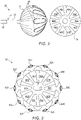
- FIG. 2 is a schematic pictorial illustration of electrode assembly 38 in accordance with a first electrode assembly embodiment of the present invention.
- electrodes 40 are attached to an exterior wall of a balloon 70.
- Balloon 70 is affixed to a tubular shaft 72 that is configured to extend from a distal end of a lumen 74 of insertion tube 30, and the balloon is configured to be deployed through the lumen into a body cavity such as heart 26.
- inflation module 60 can pump, via an inflation lumen (not shown) contained in shaft 72, a fluid (e.g., normal saline) into the balloon.
- a fluid e.g., normal saline
- Balloon 70 is typically formed from bio-compatible material such as polyethylene terephthalate (PET), polyurethane, Nylon, or Pebax.
- a first set of electrodes 40 can be fabricated with the balloon and typically comprise gold overlaying the exterior wall of the balloon. For simplicity, connections of electrodes 40 to interface 54 and modules 56 and 58 are not shown.
- electrodes 40 in the first set can be differentiated by appending a letter to the identifying numeral, so that the electrodes comprise electrodes 40A-40J.
- FIG. 3 is a schematic pictorial illustration of GUI 62, in accordance with a first GUI embodiment of the present invention.
- GUI 62 comprises a first set of electrode icons 80 that have a one-to-one correspondence with the first set of electrodes 40 attached to balloon 70, a first set of triplet selection widgets 82 and a toggle widget 84.
- icons 80 and selectable widgets 82 can be differentiated by appending a letter to the identifying numeral, so that the electrode icons comprise icons 80A-80J and the group selection widgets comprise widgets 82A-82J.
- medical system 20 is constrained to use specific groupings of electrodes 40 to perform an IRE ablation operation on tissue in a body cavity of patient 28.
- the constraint is that medical system 20 uses triplets of electrodes. For example, if a given triplet comprises the electrodes corresponding to icons 80A, 80B and 80C, then the medical system 20 performs bipolar ablation sequentially using the following pairs of electrodes:
- GUI 62 e.g., using input devices 66 or touchscreen 64
- processor 46 can select/deselect a respective triplet of electrode icons 80 (and thereby select/deselect their corresponding electrodes 40 for IRE ablation) per the following table: Widget Triplet 82A 80J, 80A, 80B 82B 80A, 80B, 80C 82C 80B, 80C, 80D 82D 80C, 80D, 80E 82E 80D, 80E, 80F 82F 80E, 80F, 80G 82G 80F, 80G, 80H, 801 821 80H, 801, 80J 82J 801, 80J, 80A
- toggle widget 84 is similar to an on/off switch in that in response to medical professional 34 selecting the toggle widget, processor 46 selects/deselects all icons 82 presented by the GUI in Figure 3 (i.e., icons 80A-80J).
- electrodes 40 may be selected using quad groupings (e.g., a grouping of electrodes 40 corresponding to icons 80A, 80B, 80C and 80D).
- FIG 4 is a schematic pictorial illustration of electrode assembly 38, in accordance with a second electrode assembly embodiment of the present invention.
- electrode assembly 38 comprises a second set of electrodes 40 that are affixed to an end section 90 that is formed as a complete or partial lasso, i.e., as a preformed arcuate structure.
- electrodes 40 in the second set can be differentiated by appending a letter to the identifying numeral, so that the electrodes comprise electrodes 40K-40T.
- end section 90 may also be referred to as lasso 90.
- the arcuate and possibly helical shape of end section 90 may be maintained, for example, by incorporating a thin strut made from a shape memory material, such as Nitinol (not shown), in the desired shape within the end section.
- the strut is made sufficiently flexible to permit the end section to straighten during insertion and withdrawal through lumen 74, but to resume its arcuate form when it is unconstrained inside the heart chamber.
- the second set of electrodes 40 are connected to control console 24 by wires (not shown) running through medical probe 22.
- FIG. 5 is a schematic pictorial illustration of GUI 62, in accordance with a second GUI embodiment of the present invention.
- GUI 62 comprises a second set of electrode icons 80 that have a one-to-one correspondence with the second set of electrodes 40 attached to lasso 90, a second set of group selection widgets 82 and toggle widget 84.
- icons 80 and widgets 82 can be differentiated by appending a letter to the identifying numeral, so that the electrode icons comprise icons 80K-80T, and the group selection widgets comprise widgets 82K-82R.
- GUI 62 e.g., using input devices 66 or touchscreen 64
- processor 46 can select/deselect a triplet of electrode icons 80 (and thereby select/deselect their corresponding electrodes 40 for IRE ablation) per the following table: Widget Triplet 82K 80K, 80L, 80M 82L 80L, 80M, 80N 82M 80M, 80N, 80O 82N 80N, 80O, 80P 82O 80O, 80P, 80Q 82P 80P, 80Q, 80R 82Q 80Q, 80R, 80S 82R 80R, 80S, 80T
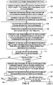
- FIG. 6 is a flow diagram that schematically illustrates a method of using GUI 62 to select and deselect triplets of adjacent electrode icons, in accordance with an embodiment of the present invention.
- medical professional 34 inserts distal end 36 of medical probe 22 into a body cavity (e.g., a chamber of heart 26) of patient 28, and in an engaging step 102, the medical professional manipulates handle 32 so that electrode assembly 38 engages tissue in the body cavity.
- a body cavity e.g., a chamber of heart 26
- processor 46 partitions electrodes 40 into a plurality of overlapping groups of adjacent electrodes 40. While the examples described herein describe groups comprising triplets that correspond to widgets 82A-82R, groups comprising any plurality of electrodes 40 (e.g., two, four or five) are considered to be within the spirit and scope of the present invention.
- processor 46 identifies a respective ablation selection status (i.e., selected or not selected) of each electrode 40.
- the ablation selection status for a given electrode 40 may comprise a selected state or a non-selected state, and ablation module 56 and switching module 58 deliver IRE ablation energy only to the electrodes that are selected (i.e., have selected states).
- processor 46 identifies a respective toggle status for each of the widgets corresponding to respective sets (e.g., triplets) of electrodes 40.
- the toggle status of a given group is indicated by the toggle status of its corresponding widget 82. Toggle statuses are described in the description referencing Figure 7 hereinbelow.
- each of the groupings comprises a triplet of electrodes 40.
- medical professional 34 selects some triplets of electrodes 40, then this may cause problems in the ablation.
- medical professional 34 may select a first triplet comprising electrodes 40B, 40C and 40D, and a second triplet comprising electrodes 40E, 40F and 40G. Even though these triplets include electrodes 40B-40G, the region of tissue between adjacent electrodes 40D and 40E is not covered (i.e., by the selected triplets).
- processor 46 can prevent this selection (i.e., of triplets 40B, 40C, 40D and 40E, 40F, 40G) to prevent any ambiguity about whether or not the region of tissue between adjacent electrodes 40D and 40E will be ablated.
- GUI 62 can prevent medical professional 34 from selecting the second triplet (i.e., to prevent forming the gap between electrodes 40D and 40E).
- GUI 62 accepts the selection of the first and second triplets, detects that the region between electrodes 40D and 40E is not covered, and automatically selects further triplets of electrodes 40C, 40D, 40E and electrodes 40D, 40E, 40F to cover the gap between electrodes 40D and 40E.
- GUI 62 can reflect these automatically selected triplets, as described in the description referencing Figure 15 hereinbelow.
- GUI 62 automatically selecting triplets 40C, 40D, 40E and 40D, 40E, 40F ensures that medical system 20 can deliver an even amount of ablation energy to the region of tissue encompassed by electrodes 40B and 40G.
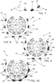
- Figure 7 is a schematic pictorial illustration that shows examples of visual configurations 130-136 of widgets 82 that GUI 62 can use to indicate a toggle status of a corresponding triplet of electrodes 40, in accordance with an embodiment of the present invention.
- the toggle status for a given triplet of electrodes 40 indicates whether or not the given triplets are selected or deselected, and whether or not the ablation selection status of the triplet electrodes can be changed.
- Figure 7 shows examples of visual configurations 130-136 of widgets 82 that GUI 62 can use to indicate a toggle status of a corresponding triplet of electrodes 40, in accordance with an embodiment of the present invention.
- the toggle status for a given triplet of electrodes 40 indicates whether or not the given triplets are selected or deselected, and whether or not the ablation selection status of the triplet electrodes can be changed.
- the toggle status of a given group indicates whether or not the group can be selected/deselected.
- the toggle status of a given group referenced by a given widget 82 comprising visual configurations 132 and 134 is selectable (i.e., the group can be selected/deselected), and a given group referenced by a given widget 82 comprising visual configurations 130 and 136 is non-selectable (i.e., the group cannot be selected/deselected).
- processor 46 presents GUI 62 comprising a set of icons 80 having a one-to-one correspondence to electrodes 40 and that indicate their respective ablation selection statuses.
- the ablation selection status for a given electrode 40 indicates whether or not the given electrode is selected.
- GUI 62 can present icons 80 using visual configurations indicating their respective ablation selection statuses. In the examples described in the description referencing Figures 8-15 hereinbelow, if a given electrode 40 is selected, then GUI 62 presents the corresponding icon 80 with shading, and if a given electrode 40 is not selected, then the GUI presents the corresponding icon 80 without shading.
- processor 45 presents, in GUI 62, a set of widgets 82 having a one-to-one correspondence to the defined triplets of electrodes 40 and that indicate their respective toggle statuses.
- the toggle status for a given triplet of electrodes 40 indicates whether or not the given triplet is selected and can be deselected, selected but cannot be deselected, not selected but can be selected, or not selected and cannot be selected.
- FIGS 8-15 are examples of how GUI 62 can present icons 80 and widgets 82, in accordance with an embodiment of the present invention.
- GUI 62 in Figures 8-13 can be used to control the electrode assembly described in the description referencing Figures 4 and 5 hereinabove
- the GUI in Figures 14 and 15 can be used to control the electrode assembly described in the description referencing Figures 2 and 3 hereinabove.
- GUI 62 presents all widgets 82 using visual configuration 132, thereby indicating that no electrodes 40 are currently selected for ablation. Therefore, GUI 62 presents all icons 80 without shading.
- processor 46 selects electrodes 40 corresponding to icons 80L - 80N.
- GUI 62 presents widget 82L using visual configuration 134 and icons 80L-80N with shading indicating that electrodes 40L-40N are selected for ablation.
- the example presented in Figure 9 can immediately follow the example presented in Figure 8 .
- processor 46 selects electrodes 40 corresponding to icons 80L-80Q.
- GUI 62 presents widgets 82L-82O using visual configuration 134 and icons 80L-80Q with shading indicating that electrodes 40L-40Q are selected for ablation.
- medical professional 34 can select the electrodes corresponding to icons 80L-80Q by selecting widgets 82L and 82O, and GUI 62 automatically "fills in" (i.e. by selecting) widgets 82M and 82N.
- the example presented in Figure 10 can immediately follow the example presented in Figure 9 .
- processor 46 selects electrodes 40 corresponding to icons 80L-80N and 80P-80R.
- GUI 62 presents widgets 82L and 82P using visual configuration 134 and icons 80L-80N and 80P-80R with shading indicating that electrodes 40L-40N and electrodes 40P-40R are selected for ablation.
- GUI 62 can transition from the configuration presented in Figure 9 to the configuration presented in Figure 11 in response to medical professional 34 clicking on (i.e., selecting) widget 82P.
- GUI 62 can transition from the configuration presented in Figure 10 to the configuration presented in Figure 11 in response to medical professional 34 clicking on the following sequence of widgets 82:
- GUI 62 can transition from the configuration presented in Figure 10 to the configuration presented in Figure 11 in response to medical professional 34 clicking on the following sequence of widgets 82:
- the electrode corresponding to icon 80O is not selected. Therefore, this example enables medical professional 34 to configure (i.e., via GUI 62) medical system 20 to perform IRE ablation with a gap (i.e., the area of tissue engaged by the electrode corresponding to icon 80O).
- processor 46 selects electrodes 40 corresponding to icons 80K-80T (i.e., all the icons in Figure 12 ) for ablation.
- medical professional 34 clicks on all widgets 82K-82R (i.e., GUI 62 does not automatically "fill in” any of the widgets), and during the selection, GUI 62 prevents the medical professional from selecting any of the widgets that can result in uneven ablation by electrodes 40.
- GUI 62 presents widgets 82K and 82R using visual configuration 134, widgets 82L-82Q using visual configuration 136 and icons 80K-80T (i.e., all the icons in Figure 12 ) with shading indicating that electrodes 40K-40T are selected for ablation.
- processor 46 can select electrodes 40 corresponding to icons 80K-80T in response to medical professional 34 "sliding" toggle widget 84 from left to right, thereby selecting the electrodes corresponding to all the icons in Figure 12 .
- GUI 62 presents widgets 82K and 82P using visual configuration 132, widgets 82L and 82O using visual configuration 134, widgets 82M and 82N using visual configuration 136, widgets 82Q and 82R using visual configuration 130, icons 80L-80Q with shading indicating that electrodes 40L-40Q are selected for ablation, and icons 80K and 80R-80T without shading.
- GUI 62 prevents the medical professional from selecting any of the widgets that can result in uneven ablation by electrodes 40.
- processor 46 selects electrodes 40 corresponding to icons 80A-80J (i.e., all the icons in Figure 14 ).
- GUI 62 presents widgets 82A-82J using visual configuration 134, and icons 80A-80J (i.e., all the icons in Figure 14 ) with shading indicating that electrodes 40A-40J are selected for ablation.
- processor 46 can select electrodes 40 corresponding to icons 80K-80T in response to medical professional 34 "sliding" toggle widget 84 from left to right, thereby selecting the electrodes corresponding to all the icons in Figure 14 .
- FIG. 12 While both Figures 12 and 14 show the respective ablation selection statuses of all electrodes 40 as "selected", the toggle statuses of widgets 82 differ in the two figures. This is due to the different configurations of the electrode assemblies presented in those Figures.
- the electrode assembly presented in Figure 12 corresponds to the lasso-shaped electrode assembly shown in Figure 4 and the electrode assembly presented in Figure 14 corresponds to the balloon-shaped electrode assembly shown in Figure 2 .
- a given widget 82 corresponding to a given group of the electrodes comprising electrodes 40A and 40J
- none of the widgets for the lasso-shaped electrode assembly correspond to a group of the electrodes comprising electrodes 40K and 40T.
- medical professional 34 can select electrodes 40A-40J (i.e., to transition from the configuration of widgets 82 shown in Figure 3 to the configuration shown in Figure 14 ) by clicking at least four widgets 82.
- medical professional 34 can select electrodes 40A-40J by clicking one of the following sequence of widgets 82: 82A, 82B, 82C, 82D, 82E, 82F, 82G and 82H.
- the GUI can automatically select widgets 801 and 80J in order to prevent a gap in ablation between electrodes 401 and 40J.
- medical professional 34 can select electrodes 40A-40J by clicking on one of the following sequence of widgets 82:
- GUI 62 selects all electrodes 40 in response to input received from medical professional 34
- the respective visual configurations of the widgets are different in these two examples.
- medical professional 34 must click on a given widget 82 to either select or deselect specific electrodes 40.
- GUI 62 will only enable medical professional 34 to click on widgets 82L (i.e., so as to select electrode 40N) and 82K (i.e., so as to deselect electrodes 40K-40M).
- electrodes 40A-40J were selected automatically by GUI 62.
- medical professional 34 can select electrodes 40A-40J by either "sliding" toggle widget 84 from left to right, or by clicking on at least four widgets 82 as described in the examples hereinabove.
- processor 46 can automatically "select" widgets 82D and 82F, thereby deselecting electrodes 40 corresponding to icon 80E).
- electrodes 40D and 40F are selected and electrode 40E (corresponding to icon 80E) is not selected, thereby creating a gap (i.e., for the ablation) in the region of tissue in contact with electrode 40E.
- GUI 62 presents widgets 82A-82C and 82G-J using visual configuration 134, widgets 82D-F using visual configuration 132, icons 80A-80D and 80F-80J with shading (indicating that electrodes 40F-40J are selected for ablation) and icon 80E without shading.
- processor 46 receives an input indicating a selection of a given widget 82.
- processor 46 can receive the input in response to medical professional 34 using input devices 66 or touchscreen 64 to click on the given widget.
- the given widget corresponds to a triplet of electrodes 40 that are in contact with a region of tissue in heart 26, and medical professional 34 can select the given widget in order to select or deselect the region of tissue (i.e., for IRE ablation).
- a given widget can be selected (i.e., based on its toggle status)
- processor 46 identifies, in the triplet of electrodes 40 corresponding to the given widget, one or more of the electrodes, whose respective statuses need to be toggled (i.e., from selected to deselected or from deselected to selected) in response to the selection of the given widget.
- a given widget can be selected if the given widget on display 64 comprises visual configuration 132 or 134.
- processor 46 toggles the ablation selection status (i.e., for ablation as described supra) of the identified one or more electrodes, and toggles, on display 64, a visual configuration of the corresponding one or more electrode icons 80 (e.g., from shaded to not shaded or from not shaded to shaded).
- IRE ablation module 56 delivers IRE ablation energy to the selected electrodes. However, if the selection of electrodes 40 is not complete, then the method continues with step 106.
- step 116 if the given widget cannot be selected, then the method continues with step 106.
- a given widget cannot be selected if the given widget on display 64 comprises visual configuration 130 or 136.
Landscapes
- Health & Medical Sciences (AREA)
- Life Sciences & Earth Sciences (AREA)
- Surgery (AREA)
- Engineering & Computer Science (AREA)
- Veterinary Medicine (AREA)
- General Health & Medical Sciences (AREA)
- Public Health (AREA)
- Animal Behavior & Ethology (AREA)
- Biomedical Technology (AREA)
- Heart & Thoracic Surgery (AREA)
- Medical Informatics (AREA)
- Molecular Biology (AREA)
- Nuclear Medicine, Radiotherapy & Molecular Imaging (AREA)
- Otolaryngology (AREA)
- Plasma & Fusion (AREA)
- Physics & Mathematics (AREA)
- Cardiology (AREA)
- Pathology (AREA)
- Human Computer Interaction (AREA)
- Robotics (AREA)
- Surgical Instruments (AREA)
Applications Claiming Priority (2)
| Application Number | Priority Date | Filing Date | Title |
|---|---|---|---|
| US202063128878P | 2020-12-22 | 2020-12-22 | |
| US17/536,492 US20220192742A1 (en) | 2020-12-22 | 2021-11-29 | Bipolar ablation graphical user interface |
Publications (1)
| Publication Number | Publication Date |
|---|---|
| EP4018955A1 true EP4018955A1 (fr) | 2022-06-29 |
Family
ID=78957672
Family Applications (1)
| Application Number | Title | Priority Date | Filing Date |
|---|---|---|---|
| EP21216312.5A Pending EP4018955A1 (fr) | 2020-12-22 | 2021-12-21 | Interface utilisateur graphique pour l'ablation bipolaire |
Country Status (5)
| Country | Link |
|---|---|
| US (1) | US20220192742A1 (fr) |
| EP (1) | EP4018955A1 (fr) |
| JP (1) | JP2022099317A (fr) |
| CN (1) | CN114652427A (fr) |
| IL (1) | IL288829A (fr) |
Families Citing this family (1)
| Publication number | Priority date | Publication date | Assignee | Title |
|---|---|---|---|---|
| WO2024076488A1 (fr) * | 2022-10-03 | 2024-04-11 | St. Jude Medical, Cardiology Division, Inc. | Afficheur pour proximité d'électrode |
Citations (12)
| Publication number | Priority date | Publication date | Assignee | Title |
|---|---|---|---|---|
| US5944022A (en) | 1997-04-28 | 1999-08-31 | American Cardiac Ablation Co. Inc. | Catheter positioning system |
| US5983126A (en) | 1995-11-22 | 1999-11-09 | Medtronic, Inc. | Catheter location system and method |
| US6456864B1 (en) | 1994-10-11 | 2002-09-24 | Ep Technologies, Inc. | Systems and methods for guiding movable electrode elements within multiple-electrode structures |
| US6625482B1 (en) | 1998-03-06 | 2003-09-23 | Ep Technologies, Inc. | Graphical user interface for use with multiple electrode catheters |
| WO2007024983A2 (fr) * | 2005-08-22 | 2007-03-01 | Ablation Frontiers | Interface utilisateur pour systeme d'ablation tissulaire |
| US20080262489A1 (en) * | 2007-04-23 | 2008-10-23 | Minnow Medical, Llc | Thrombus removal |
| WO2014179110A1 (fr) * | 2013-05-03 | 2014-11-06 | St. Jude Medical, Cardiology Division, Inc. | Système, procédés et organes de commande pour ablation |
| US9844406B2 (en) | 1999-05-04 | 2017-12-19 | Mederi Therapeutics, Inc. | Graphical user interface for association with an electrode structure deployed in contact with a tissue region |
| US20190175265A1 (en) | 2017-12-13 | 2019-06-13 | Biosense Webster (Israel) Ltd. | Graphical User Interface (GUI) for Displaying Estimated Cardiac Catheter Proximity to the Esophagus |
| EP3206613B1 (fr) * | 2014-10-14 | 2019-07-03 | Farapulse, Inc. | Appareil pour l'ablation rapide et sûre d'une veine cardiopulmonaire |
| US10470826B2 (en) | 2012-05-21 | 2019-11-12 | Kardium Inc. | Systems and methods for selecting, activating, or selecting and activating transducers |
| WO2020159903A1 (fr) * | 2019-01-29 | 2020-08-06 | Boston Scientific Scimed Inc | Sélection intelligente de puissance pour système d'ablation rf à électrodes multiples |
Family Cites Families (6)
| Publication number | Priority date | Publication date | Assignee | Title |
|---|---|---|---|---|
| JPH1033551A (ja) * | 1996-07-29 | 1998-02-10 | Olympus Optical Co Ltd | バイポーラ鉗子 |
| US20190083169A1 (en) * | 2008-05-09 | 2019-03-21 | Angiodynamics, Inc. | Techniques for Controlling an Irreversible Electroporation System |
| CA2850773C (fr) * | 2011-10-04 | 2020-04-28 | Vessix Vascular, Inc. | Appareil et procede de traitement d'une restenose sur endoprothese |
| EP3410972B1 (fr) * | 2016-02-02 | 2021-03-10 | Innoblative Designs, Inc. | Système d'ablation de tissu cavitaire |
| US11052246B2 (en) * | 2017-07-28 | 2021-07-06 | Medtronic, Inc. | Expandable elements for delivery of electric fields |
| US20200297415A1 (en) * | 2019-03-22 | 2020-09-24 | Boston Scientific Scimed Inc. | Automated electrode recommendation for ablation systems |
-
2021
- 2021-11-29 US US17/536,492 patent/US20220192742A1/en active Pending
- 2021-12-09 IL IL288829A patent/IL288829A/en unknown
- 2021-12-21 JP JP2021206829A patent/JP2022099317A/ja active Pending
- 2021-12-21 EP EP21216312.5A patent/EP4018955A1/fr active Pending
- 2021-12-22 CN CN202111579869.2A patent/CN114652427A/zh active Pending
Patent Citations (13)
| Publication number | Priority date | Publication date | Assignee | Title |
|---|---|---|---|---|
| US6456864B1 (en) | 1994-10-11 | 2002-09-24 | Ep Technologies, Inc. | Systems and methods for guiding movable electrode elements within multiple-electrode structures |
| US5983126A (en) | 1995-11-22 | 1999-11-09 | Medtronic, Inc. | Catheter location system and method |
| US5944022A (en) | 1997-04-28 | 1999-08-31 | American Cardiac Ablation Co. Inc. | Catheter positioning system |
| US6625482B1 (en) | 1998-03-06 | 2003-09-23 | Ep Technologies, Inc. | Graphical user interface for use with multiple electrode catheters |
| US9844406B2 (en) | 1999-05-04 | 2017-12-19 | Mederi Therapeutics, Inc. | Graphical user interface for association with an electrode structure deployed in contact with a tissue region |
| US20140171942A1 (en) | 2005-08-22 | 2014-06-19 | Medtronic Ablation Frontiers Llc | User interface for tissue ablation system |
| WO2007024983A2 (fr) * | 2005-08-22 | 2007-03-01 | Ablation Frontiers | Interface utilisateur pour systeme d'ablation tissulaire |
| US20080262489A1 (en) * | 2007-04-23 | 2008-10-23 | Minnow Medical, Llc | Thrombus removal |
| US10470826B2 (en) | 2012-05-21 | 2019-11-12 | Kardium Inc. | Systems and methods for selecting, activating, or selecting and activating transducers |
| WO2014179110A1 (fr) * | 2013-05-03 | 2014-11-06 | St. Jude Medical, Cardiology Division, Inc. | Système, procédés et organes de commande pour ablation |
| EP3206613B1 (fr) * | 2014-10-14 | 2019-07-03 | Farapulse, Inc. | Appareil pour l'ablation rapide et sûre d'une veine cardiopulmonaire |
| US20190175265A1 (en) | 2017-12-13 | 2019-06-13 | Biosense Webster (Israel) Ltd. | Graphical User Interface (GUI) for Displaying Estimated Cardiac Catheter Proximity to the Esophagus |
| WO2020159903A1 (fr) * | 2019-01-29 | 2020-08-06 | Boston Scientific Scimed Inc | Sélection intelligente de puissance pour système d'ablation rf à électrodes multiples |
Also Published As
| Publication number | Publication date |
|---|---|
| CN114652427A (zh) | 2022-06-24 |
| JP2022099317A (ja) | 2022-07-04 |
| US20220192742A1 (en) | 2022-06-23 |
| IL288829A (en) | 2022-07-01 |
Similar Documents
| Publication | Publication Date | Title |
|---|---|---|
| EP3841996B1 (fr) | Interface graphique pour fonctionnement sélectif de cathéters à électrodes multiples | |
| US12295720B2 (en) | Visual guidance for positioning a distal end of a medical probe | |
| US20260096779A1 (en) | Catheter system and methods of medical uses of same, including diagnostic and treatment uses for the heart | |
| EP3791819A1 (fr) | Interface utilisateur graphique pour un système d'ablation à électrodes multiples | |
| CN110461262A (zh) | 电穿孔系统和激励导管的方法 | |
| US20230009573A1 (en) | Ablation and mapping with a singular multi-electrode catheter | |
| US12551269B2 (en) | Displaying indications of mutual distances among electrodes of a flexible ablation catheter | |
| US20210004145A1 (en) | Ablation system with graphical user interface | |
| US20220192742A1 (en) | Bipolar ablation graphical user interface | |
| EP3821838A1 (fr) | Positionnement précis et visualisation de forme d'étiquettes d'ablation de cathéter à ballonnet | |
| EP3744279B1 (fr) | Utilisation d'isolation de veine pulmonaire pour des patients souffrant de fibrillation auriculaire |
Legal Events
| Date | Code | Title | Description |
|---|---|---|---|
| PUAI | Public reference made under article 153(3) epc to a published international application that has entered the european phase |
Free format text: ORIGINAL CODE: 0009012 |
|
| STAA | Information on the status of an ep patent application or granted ep patent |
Free format text: STATUS: THE APPLICATION HAS BEEN PUBLISHED |
|
| AK | Designated contracting states |
Kind code of ref document: A1 Designated state(s): AL AT BE BG CH CY CZ DE DK EE ES FI FR GB GR HR HU IE IS IT LI LT LU LV MC MK MT NL NO PL PT RO RS SE SI SK SM TR |
|
| STAA | Information on the status of an ep patent application or granted ep patent |
Free format text: STATUS: REQUEST FOR EXAMINATION WAS MADE |
|
| 17P | Request for examination filed |
Effective date: 20221223 |
|
| RBV | Designated contracting states (corrected) |
Designated state(s): AL AT BE BG CH CY CZ DE DK EE ES FI FR GB GR HR HU IE IS IT LI LT LU LV MC MK MT NL NO PL PT RO RS SE SI SK SM TR |
|
| STAA | Information on the status of an ep patent application or granted ep patent |
Free format text: STATUS: EXAMINATION IS IN PROGRESS |
|
| 17Q | First examination report despatched |
Effective date: 20250328 |