EP4019092A1 - Dispositif d'ancrage - Google Patents
Dispositif d'ancrage Download PDFInfo
- Publication number
- EP4019092A1 EP4019092A1 EP20461603.1A EP20461603A EP4019092A1 EP 4019092 A1 EP4019092 A1 EP 4019092A1 EP 20461603 A EP20461603 A EP 20461603A EP 4019092 A1 EP4019092 A1 EP 4019092A1
- Authority
- EP
- European Patent Office
- Prior art keywords
- movable jaw
- lock
- tension members
- anchoring
- teeth
- Prior art date
- Legal status (The legal status is an assumption and is not a legal conclusion. Google has not performed a legal analysis and makes no representation as to the accuracy of the status listed.)
- Withdrawn
Links
Images
Classifications
-
- F—MECHANICAL ENGINEERING; LIGHTING; HEATING; WEAPONS; BLASTING
- F16—ENGINEERING ELEMENTS AND UNITS; GENERAL MEASURES FOR PRODUCING AND MAINTAINING EFFECTIVE FUNCTIONING OF MACHINES OR INSTALLATIONS; THERMAL INSULATION IN GENERAL
- F16B—DEVICES FOR FASTENING OR SECURING CONSTRUCTIONAL ELEMENTS OR MACHINE PARTS TOGETHER, e.g. NAILS, BOLTS, CIRCLIPS, CLAMPS, CLIPS OR WEDGES; JOINTS OR JOINTING
- F16B45/00—Hooks; Eyes
- F16B45/02—Hooks with pivoting or elastically bending closing member
- F16B45/023—Hooks with pivoting or elastically bending closing member the closing member pivoting about an axis perpendicular to the plane of the hook
-
- A—HUMAN NECESSITIES
- A62—LIFE-SAVING; FIRE-FIGHTING
- A62B—DEVICES, APPARATUS OR METHODS FOR LIFE-SAVING
- A62B35/00—Safety belts or body harnesses; Similar equipment for limiting displacement of the human body, especially in case of sudden changes of motion
- A62B35/0043—Lifelines, lanyards, and anchors therefore
- A62B35/0068—Anchors
-
- A—HUMAN NECESSITIES
- A62—LIFE-SAVING; FIRE-FIGHTING
- A62B—DEVICES, APPARATUS OR METHODS FOR LIFE-SAVING
- A62B35/00—Safety belts or body harnesses; Similar equipment for limiting displacement of the human body, especially in case of sudden changes of motion
- A62B35/0043—Lifelines, lanyards, and anchors therefore
- A62B35/0075—Details of ropes or similar equipment, e.g. between the secured person and the lifeline or anchor
-
- F—MECHANICAL ENGINEERING; LIGHTING; HEATING; WEAPONS; BLASTING
- F16—ENGINEERING ELEMENTS AND UNITS; GENERAL MEASURES FOR PRODUCING AND MAINTAINING EFFECTIVE FUNCTIONING OF MACHINES OR INSTALLATIONS; THERMAL INSULATION IN GENERAL
- F16B—DEVICES FOR FASTENING OR SECURING CONSTRUCTIONAL ELEMENTS OR MACHINE PARTS TOGETHER, e.g. NAILS, BOLTS, CIRCLIPS, CLAMPS, CLIPS OR WEDGES; JOINTS OR JOINTING
- F16B45/00—Hooks; Eyes
- F16B45/02—Hooks with pivoting or elastically bending closing member
- F16B45/027—Hooks with pivoting or elastically bending closing member and having position-locking means for the closing member
Definitions
- the object of the invention is an anchoring device, in particular intended for load-bearing towers.
- Load-bearing towers are currently one of the main means of supporting the ceilings of buildings or viaducts during construction works, in particular when pouring concrete into the structure.
- the widespread use of the said towers and their solid metal structure provide preferable possibilities for using the towers as anchoring elements for construction workers.
- the load-bearing towers are characterised by a slender structure, and the specially shaped profile forming the inner and outer sleeve ensures sufficient strength (especially against buckling and compression).
- Means of protection against falls from a height are divided into collective and individual.
- Means of individual protection is understood as means worn or held by the worker to protect him from one or more threats.
- Means of individual protection are used, among others, to arrest, stop and cushion the fall and to establish position during work. When arresting the fall, braking takes place, where the braking force depends on the braking distance. In order to ensure safe working conditions, it is assumed that the impact force must not exceed 6 kN.
- a suitable harness and a shock-absorbing system connected to an anchorage point are used. Connecting and shock-absorbing means (e.g. in the form of a cord connected to the harness) are attached to an anchorage point located in a suitable place.
- the basic anchorage points are structural points intended to be mounted on walls, ceilings, lintels. They are permanently fixed in the ground, e.g. by means of appropriate anchors.
- temporary portable anchoring devices which include in particular: (i) strap and cord fasteners (allowing to create an anchorage point on poles, beams and other elements that can be embraced with such a fastener), (ii) transverse beams (stretched between structural elements, e.g. doors), (iii) rescue tripods (used for belaying when working in confined spaces).
- strap and cord fasteners allowing to create an anchorage point on poles, beams and other elements that can be embraced with such a fastener
- transverse beams sinoiretched between structural elements, e.g. doors
- rescue tripods used for belaying when working in confined spaces.
- devices for anchoring with a horizontal rope
- devices for anchoring with a horizontal rail and (vi) inertial anchoring masses intended for use on horizontal surfaces.
- the object of the invention is an element of individual protection - a new anchoring device - that allows locating an anchorage point on structural elements with a cross-section similar to a circle (e.g. round or oval).
- the currently used strap and cord fasteners (allowing an anchorage point to be created on poles, beams and other elements that can be embraced with such a fastener) require extensive experience in installation and time-consuming assembly.
- the belaying point is a rope or a strap suitably wrapped around a structural element, a pole or a tree of adequate strength.
- the loop can be tightened with the overhand knot.
- the safety rope is connected to the belaying point by means of a screwed carabiner or two unscrewed carabiners attached with their locks oppositely [ K. Buchman: Wspinaczka linkowa. Alpinizmurgimystowy. Materiafy instruktazowe, Wroctaw, 2013 ).
- an anchoring device for irregularly shaped elements, intended for belaying during works performed at heights.
- the device according to this solution consists of an elastic, tensile-resistant strap or belt and is provided with a closing element which can be used simultaneously for closing and tightening it at the anchorage point.
- the device also comprises at least three additional reinforcements equipped with hooks movable along the strap or belt, intended for anchoring the device at the anchorage point.
- an anchoring device used for anchoring on a structural element with an oval cross-section, consisting of two clamps positioned on a common axis and a connecting element designed to enable fastening of a rope connecting the device to an element of protective equipment, wherein both clamps are extended, and at their extensions there are oblong holes directed in opposite directions and connected with a pin.
- the design of this device does not allow it to be used on vertical elements because the connecting element is not resistant to bending and in the event of the fall of the belayed person from a height it is at risk of breaking.
- a device for belaying people working at height consisting of two half-hoops connected in such a way that allows them to be closed and opened, and a clamp-closing/opening element connected to them in the form of a handle provided with closure lock.
- This handle allows the user to easily open and close the device by squeezing the handle and also allows the locking of the clamps to be released by means of cords attached to the closing element.
- this device is only suitable for securing the belayed person in the event of a fall. This device is not intended to stop a falling person (they will not stop in a specific position on a vertical element of the structure).
- the object of the invention is to develop a new anchoring device, small in size and at the same time with a structure resistant to breaking, tearing or abrasion, easy to build and operate, for universal use, especially for belaying workers working at height, preferably fastened around the seat post constituting an element of the load-bearing tower.
- the essence of the invention is an anchoring device with a shape similar to a circle, comprising a handle and an articulated assembly of a body and a movable jaw provided with teeth, the body being provided with a lock consisting of two interconnected shaped pieces and two tension members hingedly connected to the shaped pieces and to the body by means of a bolt, the tension members being ended with a lock pin.
- the movable jaw is provided with an arched guard for teeth which preferably constitutes one piece with the movable jaw.
- the body is provided with a hook which is articulated with the body, and the shaped piece located on the hook side is provided with a tab.
- the lock pin is provided with a movable, preferably spring-loaded, latch.
- the tension members of the lock are connected to each other by means of an upper plate.
- the articulation bolt is a pin.
- the handle has the shape of a ring.
- round-shaped anti-slip pads are fitted around the body and the movable jaw.
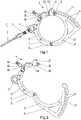
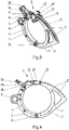
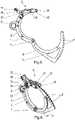
- An anchoring device comprises a body 1, a movable jaw 2, a lock 3, anti-slip pads 4', 4".
- the half-hoop-shaped body 1 is preferably provided with a permanently attached ear-shaped handle 5 for engaging a connector 6, preferably a steel carabiner, which connects the anchoring device to the unshown harness of the user via a shock-absorbing cord 7.
- the body 1 is equipped with a lock 3 in the form of an eccentric latch.
- the body 1 is articulated to one of the ends of the movable jaw 2, also in the shape of a half-hoop.
- the body 1 and the movable jaw 2 connected together form a clamp having an almost circular shape.
- the articulation bolt can be a pin 8.
- the movable jaw 2 is provided with inclined teeth 9 for anchoring it in the lock 3 by means of a lock pin 10.
- the movable jaw 2 may additionally be provided with an arched guard 11 for teeth, preferably forming one piece with the movable jaw.
- the blockade 3 is composed of two interconnected shaped pieces 12', 12" and two tension members 13', 13" hingedly connected to the shaped pieces 12', 12" and to the body 1 by means of a bolt 14.
- the shaped pieces 12', 12" can be locked in the body 1 by means of a hook 15 pivotally connected to the body 1.
- the tension members 13', 13" are ended with the lock pin 10 intended for latching the lock 3 between the teeth 9 of the movable jaw 2.
- the locking pin 10 may be provided with a spring-loaded latch 16.
- the lock tension members 13', 13" can be additionally connected to each other by means of an upper plate 17 arranged thereon.
- round-shaped anti-slip pads 4 ', 4 " are fitted.
- the movable jaw 2 is preferably provided with a dozen or so teeth 9 in order to allow adaptation of the anchoring device to structural elements of various diameters.
- the operation of the device according to the invention is based on the use of the leverage principle and the friction effect between the device, in particular the anti-slip pads 4', 4", and the element around which it is placed. It is recommended to make anti-slip pads 4', 4" of a soft material (e.g. rubber or silicone) to maximally multiply the contact surface of both elements.
- a soft material e.g. rubber or silicone
- the device according to the invention can be used not only as an anchoring element placed on vertical elements of the structure, but also as a traditional belaying hook placed on horizontal or diagonal elements of various profiles.
Landscapes
- Engineering & Computer Science (AREA)
- General Engineering & Computer Science (AREA)
- Health & Medical Sciences (AREA)
- General Health & Medical Sciences (AREA)
- Business, Economics & Management (AREA)
- Emergency Management (AREA)
- Mechanical Engineering (AREA)
- Emergency Lowering Means (AREA)
Priority Applications (1)
| Application Number | Priority Date | Filing Date | Title |
|---|---|---|---|
| EP20461603.1A EP4019092A1 (fr) | 2020-12-23 | 2020-12-23 | Dispositif d'ancrage |
Applications Claiming Priority (1)
| Application Number | Priority Date | Filing Date | Title |
|---|---|---|---|
| EP20461603.1A EP4019092A1 (fr) | 2020-12-23 | 2020-12-23 | Dispositif d'ancrage |
Publications (1)
| Publication Number | Publication Date |
|---|---|
| EP4019092A1 true EP4019092A1 (fr) | 2022-06-29 |
Family
ID=74666409
Family Applications (1)
| Application Number | Title | Priority Date | Filing Date |
|---|---|---|---|
| EP20461603.1A Withdrawn EP4019092A1 (fr) | 2020-12-23 | 2020-12-23 | Dispositif d'ancrage |
Country Status (1)
| Country | Link |
|---|---|
| EP (1) | EP4019092A1 (fr) |
Cited By (1)
| Publication number | Priority date | Publication date | Assignee | Title |
|---|---|---|---|---|
| US20210316697A1 (en) * | 2015-12-18 | 2021-10-14 | Eddy Current Limited Partnership | Variable behavior control mechanism for a motive system |
Citations (9)
| Publication number | Priority date | Publication date | Assignee | Title |
|---|---|---|---|---|
| FR2098957A5 (fr) * | 1970-07-31 | 1972-03-10 | Lavalette Georges De | |
| US4225013A (en) * | 1979-05-03 | 1980-09-30 | Sample George A | Upright climbing and platform device |
| CZ278048B6 (en) * | 1991-07-29 | 1993-07-14 | Prototypa Brno | Handcuffs |
| DE68906112T2 (de) * | 1988-09-06 | 1993-11-04 | Marcel Peltier | Schutzvorrichtung fuer persoenliche absturzsicherungsausruestung. |
| EP1452206B1 (fr) | 2003-02-26 | 2007-09-26 | Dalloz Fall Protection | Dispositif d'ancrage pour appareil de sécurité |
| WO2009118437A1 (fr) | 2008-03-28 | 2009-10-01 | Dominguez Moreno Domingo Aleja | Dispositif d'ancrage à des corps irréguliers |
| CN201836198U (zh) * | 2010-11-06 | 2011-05-18 | 宏泰电器有限公司 | 扣合式挂钩 |
| KR101958332B1 (ko) | 2017-03-23 | 2019-03-14 | 인천대학교 산학협력단 | 안전걸이장치 |
| KR102152443B1 (ko) * | 2018-05-10 | 2020-09-04 | 주기철 | 산업안전용 연결고리 |
-
2020
- 2020-12-23 EP EP20461603.1A patent/EP4019092A1/fr not_active Withdrawn
Patent Citations (9)
| Publication number | Priority date | Publication date | Assignee | Title |
|---|---|---|---|---|
| FR2098957A5 (fr) * | 1970-07-31 | 1972-03-10 | Lavalette Georges De | |
| US4225013A (en) * | 1979-05-03 | 1980-09-30 | Sample George A | Upright climbing and platform device |
| DE68906112T2 (de) * | 1988-09-06 | 1993-11-04 | Marcel Peltier | Schutzvorrichtung fuer persoenliche absturzsicherungsausruestung. |
| CZ278048B6 (en) * | 1991-07-29 | 1993-07-14 | Prototypa Brno | Handcuffs |
| EP1452206B1 (fr) | 2003-02-26 | 2007-09-26 | Dalloz Fall Protection | Dispositif d'ancrage pour appareil de sécurité |
| WO2009118437A1 (fr) | 2008-03-28 | 2009-10-01 | Dominguez Moreno Domingo Aleja | Dispositif d'ancrage à des corps irréguliers |
| CN201836198U (zh) * | 2010-11-06 | 2011-05-18 | 宏泰电器有限公司 | 扣合式挂钩 |
| KR101958332B1 (ko) | 2017-03-23 | 2019-03-14 | 인천대학교 산학협력단 | 안전걸이장치 |
| KR102152443B1 (ko) * | 2018-05-10 | 2020-09-04 | 주기철 | 산업안전용 연결고리 |
Cited By (3)
| Publication number | Priority date | Publication date | Assignee | Title |
|---|---|---|---|---|
| US20210316697A1 (en) * | 2015-12-18 | 2021-10-14 | Eddy Current Limited Partnership | Variable behavior control mechanism for a motive system |
| US11878651B2 (en) * | 2015-12-18 | 2024-01-23 | Eddy Current Limited Partnership | Variable behavior control mechanism for a motive system |
| US12606124B2 (en) | 2015-12-18 | 2026-04-21 | Surewerx Usa, Inc. | Variable behavior control mechanism for a motive system |
Similar Documents
| Publication | Publication Date | Title |
|---|---|---|
| US5036949A (en) | Motion-stopping safety system for workers | |
| AU744587B1 (en) | Improvements in roof anchors | |
| US20120055738A1 (en) | Construction safety hanger | |
| CA2108633C (fr) | Ancrage de cable antichute a fixer aux rails | |
| US10890029B2 (en) | Fall arrest ladder system | |
| AU2009308798B2 (en) | Mobile eave hook system and method | |
| US20150284968A1 (en) | I-beam-attachable lifeline system | |
| US11136823B1 (en) | Ladder fall protection system and fall arrester | |
| US5806628A (en) | Climbing device for building frames | |
| US20160375282A1 (en) | Step unit with fall arrest capability | |
| US20080110117A1 (en) | Multi-level fall protection system for high-rise construction | |
| US20050189171A1 (en) | Safety system and method of use for high workers | |
| WO2021011585A1 (fr) | Système de prévention de chute | |
| US20160096046A1 (en) | Step unit with fall arrest capability | |
| EP3831450A1 (fr) | Dispositif d'écretage à distance | |
| US5813486A (en) | D-ring anchorage connector | |
| US9956436B2 (en) | Rope access equipment | |
| US10744353B2 (en) | Roof anchor and safety system and method of using the same | |
| WO2019071337A1 (fr) | Système antichute | |
| US12006687B2 (en) | Rebar biter | |
| JP7485347B2 (ja) | ロープ(ザイル)降下用臨時支点装置 | |
| WO2019171266A1 (fr) | Pince permettant de soulever des tuyaux et des tubes d'échafaudage | |
| AU2002301550B2 (en) | Fall Restraint Device | |
| WO2020041837A1 (fr) | Dispositif et procédé permettant de fixer un lien de raccordement | |
| KR200497936Y1 (ko) | 결속 해제가 어려운 안전대용 죔줄 |
Legal Events
| Date | Code | Title | Description |
|---|---|---|---|
| PUAI | Public reference made under article 153(3) epc to a published international application that has entered the european phase |
Free format text: ORIGINAL CODE: 0009012 |
|
| STAA | Information on the status of an ep patent application or granted ep patent |
Free format text: STATUS: THE APPLICATION HAS BEEN PUBLISHED |
|
| STAA | Information on the status of an ep patent application or granted ep patent |
Free format text: STATUS: THE APPLICATION HAS BEEN WITHDRAWN |
|
| AK | Designated contracting states |
Kind code of ref document: A1 Designated state(s): AL AT BE BG CH CY CZ DE DK EE ES FI FR GB GR HR HU IE IS IT LI LT LU LV MC MK MT NL NO PL PT RO RS SE SI SK SM TR |
|
| 18W | Application withdrawn |
Effective date: 20220608 |