EP4019109A1 - Kühleinheit - Google Patents
Kühleinheit Download PDFInfo
- Publication number
- EP4019109A1 EP4019109A1 EP22020074.5A EP22020074A EP4019109A1 EP 4019109 A1 EP4019109 A1 EP 4019109A1 EP 22020074 A EP22020074 A EP 22020074A EP 4019109 A1 EP4019109 A1 EP 4019109A1
- Authority
- EP
- European Patent Office
- Prior art keywords
- cooling unit
- pump
- unit according
- coolant
- impeller
- Prior art date
- Legal status (The legal status is an assumption and is not a legal conclusion. Google has not performed a legal analysis and makes no representation as to the accuracy of the status listed.)
- Withdrawn
Links
Images




Classifications
-
- F—MECHANICAL ENGINEERING; LIGHTING; HEATING; WEAPONS; BLASTING
- F04—POSITIVE - DISPLACEMENT MACHINES FOR LIQUIDS; PUMPS FOR LIQUIDS OR ELASTIC FLUIDS
- F04D—NON-POSITIVE-DISPLACEMENT PUMPS
- F04D13/00—Pumping installations or systems
- F04D13/02—Units comprising pumps and their driving means
- F04D13/021—Units comprising pumps and their driving means containing a coupling
- F04D13/024—Units comprising pumps and their driving means containing a coupling a magnetic coupling
-
- F—MECHANICAL ENGINEERING; LIGHTING; HEATING; WEAPONS; BLASTING
- F04—POSITIVE - DISPLACEMENT MACHINES FOR LIQUIDS; PUMPS FOR LIQUIDS OR ELASTIC FLUIDS
- F04D—NON-POSITIVE-DISPLACEMENT PUMPS
- F04D13/00—Pumping installations or systems
- F04D13/02—Units comprising pumps and their driving means
- F04D13/06—Units comprising pumps and their driving means the pump being electrically driven
- F04D13/0666—Units comprising pumps and their driving means the pump being electrically driven the motor being of the plane gap type
-
- G—PHYSICS
- G06—COMPUTING OR CALCULATING; COUNTING
- G06F—ELECTRIC DIGITAL DATA PROCESSING
- G06F1/00—Details not covered by groups G06F3/00 - G06F13/00 and G06F21/00
- G06F1/16—Constructional details or arrangements
- G06F1/20—Cooling means
-
- B—PERFORMING OPERATIONS; TRANSPORTING
- B01—PHYSICAL OR CHEMICAL PROCESSES OR APPARATUS IN GENERAL
- B01D—SEPARATION
- B01D29/00—Filters with filtering elements stationary during filtration, e.g. pressure or suction filters, not covered by groups B01D24/00 - B01D27/00; Filtering elements therefor
- B01D29/11—Filters with filtering elements stationary during filtration, e.g. pressure or suction filters, not covered by groups B01D24/00 - B01D27/00; Filtering elements therefor with bag, cage, hose, tube, sleeve or like filtering elements
- B01D29/31—Self-supporting filtering elements
-
- B—PERFORMING OPERATIONS; TRANSPORTING
- B01—PHYSICAL OR CHEMICAL PROCESSES OR APPARATUS IN GENERAL
- B01D—SEPARATION
- B01D29/00—Filters with filtering elements stationary during filtration, e.g. pressure or suction filters, not covered by groups B01D24/00 - B01D27/00; Filtering elements therefor
- B01D29/11—Filters with filtering elements stationary during filtration, e.g. pressure or suction filters, not covered by groups B01D24/00 - B01D27/00; Filtering elements therefor with bag, cage, hose, tube, sleeve or like filtering elements
- B01D29/31—Self-supporting filtering elements
- B01D29/33—Self-supporting filtering elements arranged for inward flow filtration
-
- B—PERFORMING OPERATIONS; TRANSPORTING
- B01—PHYSICAL OR CHEMICAL PROCESSES OR APPARATUS IN GENERAL
- B01D—SEPARATION
- B01D35/00—Filtering devices having features not specifically covered by groups B01D24/00 - B01D33/00, or for applications not specifically covered by groups B01D24/00 - B01D33/00; Auxiliary devices for filtration; Filter housing constructions
- B01D35/26—Filters with built-in pumps filters provided with a pump mounted in or on the casing
-
- F—MECHANICAL ENGINEERING; LIGHTING; HEATING; WEAPONS; BLASTING
- F04—POSITIVE - DISPLACEMENT MACHINES FOR LIQUIDS; PUMPS FOR LIQUIDS OR ELASTIC FLUIDS
- F04D—NON-POSITIVE-DISPLACEMENT PUMPS
- F04D29/00—Details, component parts, or accessories
- F04D29/04—Shafts or bearings, or assemblies thereof
- F04D29/046—Bearings
- F04D29/047—Bearings hydrostatic; hydrodynamic
- F04D29/0473—Bearings hydrostatic; hydrodynamic for radial pumps
-
- F—MECHANICAL ENGINEERING; LIGHTING; HEATING; WEAPONS; BLASTING
- F04—POSITIVE - DISPLACEMENT MACHINES FOR LIQUIDS; PUMPS FOR LIQUIDS OR ELASTIC FLUIDS
- F04D—NON-POSITIVE-DISPLACEMENT PUMPS
- F04D29/00—Details, component parts, or accessories
- F04D29/04—Shafts or bearings, or assemblies thereof
- F04D29/046—Bearings
- F04D29/048—Bearings magnetic; electromagnetic
-
- F—MECHANICAL ENGINEERING; LIGHTING; HEATING; WEAPONS; BLASTING
- F04—POSITIVE - DISPLACEMENT MACHINES FOR LIQUIDS; PUMPS FOR LIQUIDS OR ELASTIC FLUIDS
- F04D—NON-POSITIVE-DISPLACEMENT PUMPS
- F04D29/00—Details, component parts, or accessories
- F04D29/18—Rotors
- F04D29/22—Rotors specially for centrifugal pumps
- F04D29/2261—Rotors specially for centrifugal pumps with special measures
- F04D29/2266—Rotors specially for centrifugal pumps with special measures for sealing or thrust balance
-
- F—MECHANICAL ENGINEERING; LIGHTING; HEATING; WEAPONS; BLASTING
- F04—POSITIVE - DISPLACEMENT MACHINES FOR LIQUIDS; PUMPS FOR LIQUIDS OR ELASTIC FLUIDS
- F04D—NON-POSITIVE-DISPLACEMENT PUMPS
- F04D29/00—Details, component parts, or accessories
- F04D29/58—Cooling; Heating; Diminishing heat transfer
- F04D29/586—Cooling; Heating; Diminishing heat transfer specially adapted for liquid pumps
- F04D29/5866—Cooling at last part of the working fluid in a heat exchanger
-
- F—MECHANICAL ENGINEERING; LIGHTING; HEATING; WEAPONS; BLASTING
- F04—POSITIVE - DISPLACEMENT MACHINES FOR LIQUIDS; PUMPS FOR LIQUIDS OR ELASTIC FLUIDS
- F04D—NON-POSITIVE-DISPLACEMENT PUMPS
- F04D29/00—Details, component parts, or accessories
- F04D29/58—Cooling; Heating; Diminishing heat transfer
- F04D29/586—Cooling; Heating; Diminishing heat transfer specially adapted for liquid pumps
- F04D29/588—Cooling; Heating; Diminishing heat transfer specially adapted for liquid pumps cooling or heating the machine
-
- F—MECHANICAL ENGINEERING; LIGHTING; HEATING; WEAPONS; BLASTING
- F04—POSITIVE - DISPLACEMENT MACHINES FOR LIQUIDS; PUMPS FOR LIQUIDS OR ELASTIC FLUIDS
- F04D—NON-POSITIVE-DISPLACEMENT PUMPS
- F04D29/00—Details, component parts, or accessories
- F04D29/70—Suction grids; Strainers; Dust separation; Cleaning
- F04D29/708—Suction grids; Strainers; Dust separation; Cleaning specially for liquid pumps
-
- G—PHYSICS
- G06—COMPUTING OR CALCULATING; COUNTING
- G06F—ELECTRIC DIGITAL DATA PROCESSING
- G06F2200/00—Indexing scheme relating to G06F1/04 - G06F1/32
- G06F2200/20—Indexing scheme relating to G06F1/20
- G06F2200/201—Cooling arrangements using cooling fluid
-
- H—ELECTRICITY
- H10—SEMICONDUCTOR DEVICES; ELECTRIC SOLID-STATE DEVICES NOT OTHERWISE PROVIDED FOR
- H10W—GENERIC PACKAGES, INTERCONNECTIONS, CONNECTORS OR OTHER CONSTRUCTIONAL DETAILS OF DEVICES COVERED BY CLASS H10
- H10W40/00—Arrangements for thermal protection or thermal control
- H10W40/40—Arrangements for thermal protection or thermal control involving heat exchange by flowing fluids
- H10W40/47—Arrangements for thermal protection or thermal control involving heat exchange by flowing fluids by flowing liquids, e.g. forced water cooling
Definitions
- the present invention relates to a cooling unit for use in cooling a computer device comprising a centrifugal pump connected to a heat exchanger to pump coolant fluid therethrough and thereby to cool the coolant fluid.
- the unit When connected for example to a supercomputer to provide cooling therefor, the unit is connected in a coolant fluid circuit which includes the heat sinks of the semiconductor chips.
- coolant fluid flows from the output of the heat exchanger of the supercomputer cooling unit to the heat sinks, where the coolant fluid cools the heat sinks, and then along a return path back to the pump.
- the pump pumps the coolant fluid to the input of the heat exchanger, where the coolant fluid is cooled before it passes out from the heat exchanger at an output therefrom, and onwards to pass around the coolant fluid circuit continuously.
- the pump has comprised an electric motor having a drive axle which passes through a bearing and a seal between the axle and an impeller housing, to an impeller of a centrifugal pump to which it is drivingly connected.
- the seal fails, coolant fluid may escape from the circuit with the possible result that the semiconductor chips overheat to such an extent that they may be damaged or even destroyed. Seal and/or bearing failure may occur through wear or through overheating as a result of cavitation in the coolant fluid, or a loss of coolant fluid from the circuit through leaks other than through the seal.
- the particles from the bearing may break away therefrom and may be carried in the coolant fluid to the heat sinks.
- the latter typically have a fine ridging or microfins or microchannels on to or within which the coolant is entrained to create turbulence or at least a better heat exchange between the heat sink and the coolant fluid, and such particles may have a detrimental effect on such heat exchange.
- the present invention seeks to provide a remedy.
- the present invention is directed to a cooling unit comprising a coolant fluid pathway in which there is (a) a centrifugal pump which serves to pump coolant fluid along the pathway when the unit is in use, and (b) a heat exchanger which serves to cool the coolant fluid which is thus pumped along the pathway, characterised in that the pump has a rotor constituted by a magnetically contactlessly driven impeller which is provided with at last one magnet and which is enclosed within a housing, and a stator outside the housing and provided with at least one electromagnet operable to act on the said at least one magnet to rotate the impeller.
- Such a construction avoids any contact between a moving and a stationery part that may give rise to frictional wear and heating.
- the impeller may be a magnetically levitated impeller so that it may be driven contactlessly.
- the impeller may be fluid-dynamically levitated so that it may be driven contactlessly.
- the coolant fluid may comprise water, with or without an additive such as a bactericide or glycol.
- This provides a fluid coolant with a high specific heat, highly effective for heat transference.
- the presence of a bactericide reduces the risk of bacteria colonies forming for example on the fine ridge formations of heat sinks when the device is in use to cool such heat sinks.
- glycol enables the unit to be used in low temperature climates.
- a cooling unit embodying the present invention may further comprise a filter in the coolant fluid pathway to filter the coolant fluid.
- Such a construction provides the further benefit of being able to remove detritus or particles resulting from wear or corrosion that may otherwise accumulate in the fluid coolant and cause a blockage or damage to the fine ridging of heat sinks when the unit is connected to cool such heat sinks.
- the filter may comprise a mesh through which the coolant fluid flows when the unit is in use.
- the filter may further comprise a cylindrical perforated wall surrounded by such a mesh.
- the hole size of the mesh may be 20 to 100 microns in diameter, preferably 50 microns.
- the filter may be attached to the pump.
- the present invention extends to a method of cooling a computer device using a unit which embodies the present invention.
- the cooling unit 10 shown in Figure 1 especially but not exclusively for cooling heat sinks of semiconductor chips of a supercomputer, comprises a primary fluid coolant pathway constituted by an inlet pipe 12 connected to the primary pathway inlet 14 of a multiplate heat exchanger 16, and a primary pathway outlet pipe 18 connected to a primary pathway outlet 20 of the heat exchanger 16.
- a radiator and pump 21 is connected in fluid communication with the inlet pipe 12 and the outlet pipe 18, to pass cooled water continuously through the heat exchanger 16.
- the cooling unit 10 also comprises a secondary coolant pathway constituted by an inlet pipe 22 connected to a secondary pathway inlet 24 of the heat exchanger 16, the secondary pathway outlet 26 of which is connected to the inlet of a filter 27 via a connecting pipe 28.
- the outlet (not shown in Figure 1 ) of the filter 27 is connected a pump 29 the outlet of which is connected to an outlet pipe 32 of the unit 10.
- the connecting pipe 28 is provided with an expansion vessel 30 to maintain a predetermined pressure of water in that pipe and hence in the filter 27 and in the inlet to the pump 29.
- a supercomputer 36 for example is connected to the inlet pipe 22 and the outlet pipe 32 of the unit 10, so that cooled water from the heat exchanger 16 is passed through the filter 27, and is pumped by the pump 29 through the outlet pipe 32 to the coolant distribution manifold (not shown) of the supercomputer 36 to conduct fluid to and cool the heat sinks (not shown) within the supercomputer.
- the water is then returned via a return manifold (not shown) to the inlet pipe 22 and thence back to the filter 27 via the heat exchanger 16 to begin the next cycle around the secondary coolant circuit.
- cooling water is pumped continuously across the heat sinks of the supercomputer 36.
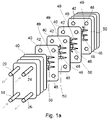
- Dividing plates 40 define primary circuit and secondary circuit pathways of the exchanger 16, the plates 40 being spaced apart and the successive spaces between the plates 40 alternately constituting parts of the primary circuit pathway and the secondary circuit pathway. This is achieved by having the primary pathway inlet 14 and the primary pathway outlet 20 opening into the first space (the space between the two left-most plates 40 in Figure 1a ), and the secondary pathway inlet 24 and the secondary pathway outlet 26 bypassing the first space and opening out into the second space between the second and third plates 40.
- Respective rings (not shown) around and between the rims of upper left-hand corner apertures 42 of the second and third plates and around and between the rims of lower left-hand corner apertures (not visible in Figure 1a ) of the second and third plates 40 connect the first space to the third.
- Respective rings (not shown) around and between the rims of upper right-hand corner apertures 46 of the third and fourth plates 40 and around and between the rims of lower right-hand corner apertures 48 of the third and fourth plates 40 connect the second space to the fourth and so on throughout the heat exchanger 16.
- Zig-zag ridges 49 on the plates 40 cause the fluids within the pathways to meander in passing from the top to the bottom or from the bottom to the top of the heat exchanger 16, as indicated by the arrows 50. This improves the exchange of heat between the fluid in the secondary pathway and the fluid in the primary pathway when the unit 10 is in use.
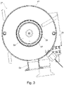
- FIG. 2 and 3 Further details of the filter 27 are shown in Figures 2 and 3 .
- the filter 27 comprises an outer cylindrical wall 51 closed by an upper circular wall 52 adjacent to which is provided the inlet 54 of the filter 27.
- One end (the lower end as viewed in Figure 2 ) of the outer cylindrical wall 51 is closed by a bottom annular wall 56.
- a central inner cylindrical perforated wall 57 surrounded everywhere by a mesh 58 of hole size 50 microns extends from the bottom wall 56 to the upper wall 52, seals being provided between the mesh 58 and both walls 52 and 56.
- the outlet 60 of the filter 27 and the inlet 62 of the pump 29 is provided by a single component 64, for example of stainless steel, which also provides the bottom wall 56 of the filter 27.
- the component has an axially extending passageway 66 flared at an upper end to provide the outlet 60 of the filter 27 and at a lower end to provide the inlet 62 of the pump 29.
- the latter is represented in block form in Figure 2 .
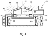
- the pump 29 has an inert plastics housing 70 having a generally circular interior within which fits an inert plastics circular impeller 72 within which are encapsulated four permanent magnets 74. These are equiangularly spaced around a lower perimeter of the impeller 72, and are so oriented that their outer poles from one magnet to the next alternate north with south.
- a stator 76 surrounds a lower part of the housing 70 (part of which is provided by the component 64) which accommodates the lower part of the impeller 72 containing the magnets 74.
- the stator 76 is constituted by twelve magnetically permeable sections 78 respective portions of which are surrounded by respective electromagnetic coils 80.
- the housing 70 has an upper aperture 82 at the inlet 62 of the pump 29, and a lateral aperture 84 at a transversely extending outlet 86 of the pump 29.
- Eight impeller blades 88 extend outwardly from an open centre 90 of the impeller 72, the blades being uniformly spaced around the impeller and spiraling radially outwardly.
- the impeller 72 When the unit is in use and an electrical current is passing through the electromagnetic coils 80, the impeller 72 is magnetically levitated, so that it is not in contact with any of the walls of the housing 70, and when it rotates it does so contactlessly.
- pump shown in Figure 6 is similar to that in Figures 4 and 5 except that in addition, outwardly and downwardly extending passageways 92 are provided in its impeller so that as it spins, coolant water is flung downwardly, so that the impeller is fluid-dynamically levitated.
- the electronic drive circuitry of the pump 29 is shown in Figure 7 . It comprises a controller 100 connected to control a sinusoidal oscillator 102. The latter is connected to the electromagnetic coils 80 via a phase splitter 104, so that each section 78 (shown in Figures 4 and 5 ) lags in phase with the next successive phase progressing around the stator 76 in a given direction by 60°, and the part of each section closest to the housing 70 alternates between being a south magnetic pole and a north magnetic pole according to the frequency of the sinusoidal oscillator, and out of phase with the next section proceeding around the stator in a given direction by 60°.
- a controller 100 connected to control a sinusoidal oscillator 102.
- the latter is connected to the electromagnetic coils 80 via a phase splitter 104, so that each section 78 (shown in Figures 4 and 5 ) lags in phase with the next successive phase progressing around the stator 76 in a given direction by 60°, and the part of each section closest to the housing 70 alternate
- FIG. 8 is a set of graphs one for each of six successive sections progressing around the stator 76.
- Each graph shows the sinusoidally varying strength of the electrical current flowing through the coil of a section as a function of time.
- Successively lower graphs show the current strength of successive sections respectively progressing around the stator 76, plotted on the same time scale.
- This variation of the current strength in the different coils 80 causes the impeller 72 to rotate at half the frequency of the oscillator 102. This in turn causes water in the impeller to be thrown outwardly and through the outlet 86 of the pump 29, so that the latter acts as a centrifugal pump.
- the radiator and pump 21 may be replaced by a pump with a chiller, a fluid cooler, or a cooling tower for example.
- the unit 10 may be connected to cool for example a high performance computer, or a rear door heat exchanger to cool air exiting a computer blade rack, so that the cooling unit cools the rack indirectly by cooling air which is circulated around the room in which the rack is located.
- magnetic levitation of the impeller 72 is achieved by having the magnetically permeable sections 78 located relative to the magnets 74 to lift the impeller 72 away from the housing 70 by magnetic forces acting between the magnetically permeable sections 78 and the magnets 74 when the pump is in use. This is irrespective of any dynamic forces acting on the impeller 72 by fluid within it or around it. This reduces the energy consumed by operation of the pump for a given output of coolant therefrom relative to a pump which uses dynamic fluid forces to lift the impeller.
Landscapes
- Engineering & Computer Science (AREA)
- General Engineering & Computer Science (AREA)
- Mechanical Engineering (AREA)
- Physics & Mathematics (AREA)
- Theoretical Computer Science (AREA)
- Chemical Kinetics & Catalysis (AREA)
- Chemical & Material Sciences (AREA)
- General Physics & Mathematics (AREA)
- Human Computer Interaction (AREA)
- Thermal Sciences (AREA)
- Fluid Mechanics (AREA)
- Electromagnetism (AREA)
- Structures Of Non-Positive Displacement Pumps (AREA)
- Cooling Or The Like Of Electrical Apparatus (AREA)
- Cooling Or The Like Of Semiconductors Or Solid State Devices (AREA)
Applications Claiming Priority (2)
| Application Number | Priority Date | Filing Date | Title |
|---|---|---|---|
| GB1713297.8A GB2565592A (en) | 2017-08-18 | 2017-08-18 | A cooling unit |
| EP18188800.9A EP3444477B1 (de) | 2017-08-18 | 2018-08-13 | Kühleinheit |
Related Parent Applications (2)
| Application Number | Title | Priority Date | Filing Date |
|---|---|---|---|
| EP18188800.9A Division-Into EP3444477B1 (de) | 2017-08-18 | 2018-08-13 | Kühleinheit |
| EP18188800.9A Division EP3444477B1 (de) | 2017-08-18 | 2018-08-13 | Kühleinheit |
Publications (1)
| Publication Number | Publication Date |
|---|---|
| EP4019109A1 true EP4019109A1 (de) | 2022-06-29 |
Family
ID=59996801
Family Applications (2)
| Application Number | Title | Priority Date | Filing Date |
|---|---|---|---|
| EP18188800.9A Active EP3444477B1 (de) | 2017-08-18 | 2018-08-13 | Kühleinheit |
| EP22020074.5A Withdrawn EP4019109A1 (de) | 2017-08-18 | 2018-08-13 | Kühleinheit |
Family Applications Before (1)
| Application Number | Title | Priority Date | Filing Date |
|---|---|---|---|
| EP18188800.9A Active EP3444477B1 (de) | 2017-08-18 | 2018-08-13 | Kühleinheit |
Country Status (4)
| Country | Link |
|---|---|
| US (1) | US10876533B2 (de) |
| EP (2) | EP3444477B1 (de) |
| CN (1) | CN109407792A (de) |
| GB (1) | GB2565592A (de) |
Families Citing this family (7)
| Publication number | Priority date | Publication date | Assignee | Title |
|---|---|---|---|---|
| EP4104681A1 (de) | 2015-10-27 | 2022-12-21 | Feltrim Pastoral Company Pty Ltd | Selbstreinigender filter für flüssigkeiten |
| EP3241608B1 (de) * | 2016-05-02 | 2020-04-08 | Levitronix GmbH | Mischvorrichtung sowie einmalvorrichtung für eine solche mischvorrichtung |
| EP3795836B1 (de) * | 2019-09-18 | 2024-11-27 | Levitronix GmbH | Zentrifugalpumpe |
| EP3865709B1 (de) * | 2020-02-13 | 2023-11-22 | Levitronix GmbH | Pumpvorrichtung, einmalvorrichtung und verfahren zum betreiben einer pumpvorrichtung |
| CN112577351A (zh) * | 2020-12-29 | 2021-03-30 | 苏州苏磁智能科技有限公司 | 一种用于密闭空间的使用磁悬浮转子的换热结构 |
| JP2022168834A (ja) * | 2021-04-26 | 2022-11-08 | レヴィトロニクス ゲーエムベーハー | 電磁回転駆動装置、遠心ポンプ、及びポンプ・ユニット |
| CN113634031B (zh) * | 2021-09-08 | 2025-01-07 | 派罗特克(广西南宁)高温材料有限公司 | 一种上吸式铝液泵的过滤装置 |
Citations (5)
| Publication number | Priority date | Publication date | Assignee | Title |
|---|---|---|---|---|
| GB2141040A (en) * | 1983-06-10 | 1984-12-12 | Aquaria Inc | Freestanding aquarium filter |
| US20040123614A1 (en) * | 2002-12-30 | 2004-07-01 | Intel Corporation (A Delaware Corporation) | Centrifugal liquid pump with perimeter magnetic drive |
| CN101122302A (zh) * | 2006-08-11 | 2008-02-13 | 富准精密工业(深圳)有限公司 | 泵 |
| US20120006509A1 (en) * | 2009-03-20 | 2012-01-12 | University Of South Carolina | Nanofluids for Thermal Management Systems |
| US20150233619A1 (en) * | 2011-06-27 | 2015-08-20 | Ebullient, Llc | Method of providing stable pump operation in a two-phase cooling system |
Family Cites Families (20)
| Publication number | Priority date | Publication date | Assignee | Title |
|---|---|---|---|---|
| US5441102A (en) * | 1994-01-26 | 1995-08-15 | Sun Microsystems, Inc. | Heat exchanger for electronic equipment |
| US6333849B1 (en) * | 1996-07-01 | 2001-12-25 | Compaq Computer Corporation | Apparatus for liquid cooling of specific computer components |
| AUPO902797A0 (en) * | 1997-09-05 | 1997-10-02 | Cortronix Pty Ltd | A rotary blood pump with hydrodynamically suspended impeller |
| DE59712162D1 (de) * | 1997-09-04 | 2005-02-17 | Levitronix Llc Waltham | Zentrifugalpumpe |
| US6227817B1 (en) * | 1999-09-03 | 2001-05-08 | Magnetic Moments, Llc | Magnetically-suspended centrifugal blood pump |
| US6668911B2 (en) * | 2002-05-08 | 2003-12-30 | Itt Manufacturing Enterprises, Inc. | Pump system for use in a heat exchange application |
| US7209355B2 (en) * | 2002-05-15 | 2007-04-24 | Matsushita Electric Industrial Co., Ltd. | Cooling device and an electronic apparatus including the same |
| JP3981628B2 (ja) * | 2002-11-28 | 2007-09-26 | 株式会社東芝 | 冷却用ポンプ並びに電気機器及びパーソナルコンピュータ |
| DE10330434A1 (de) * | 2003-07-04 | 2005-02-03 | Jostra Ag | Zentrifugal-Pumpe |
| US7682301B2 (en) * | 2003-09-18 | 2010-03-23 | Thoratec Corporation | Rotary blood pump |
| JP2005317796A (ja) * | 2004-04-28 | 2005-11-10 | Toshiba Corp | ポンプ、冷却装置および電子機器 |
| JP2006039663A (ja) * | 2004-07-22 | 2006-02-09 | Hitachi Ltd | 液循環システム及びこれを用いる液冷システム |
| JP4092358B2 (ja) * | 2006-04-24 | 2008-05-28 | 株式会社ワールドケミカル | 自吸式濾過装置 |
| DE502007004851D1 (de) * | 2007-02-14 | 2010-10-07 | Levitronix Llc | Filter-Pump-Einheit, Filter-Pump-Vorrichtung mit einer solchen Einheit sowie Verfahren zum Ausfiltern |
| US9204578B2 (en) * | 2010-02-09 | 2015-12-01 | It Aire Inc. | Systems and methods for cooling data centers and other electronic equipment |
| EP2549113B1 (de) * | 2011-07-20 | 2018-10-24 | Levitronix GmbH | Magnetischer Rotor sowie Rotationspumpe mit einem magnetischen Rotor |
| CN202875903U (zh) * | 2012-10-30 | 2013-04-17 | 浙江大学 | 一种液力悬浮式血泵 |
| JP6512792B2 (ja) * | 2014-11-06 | 2019-05-15 | 株式会社荏原製作所 | 磁気浮上型ポンプ |
| CN206058100U (zh) * | 2016-08-11 | 2017-03-29 | 吉首大学 | 磁接滤芯泵cpu水冷装置 |
| CN106839504A (zh) * | 2016-12-26 | 2017-06-13 | 曙光节能技术(北京)股份有限公司 | 用于刀片服务器的液冷装置 |
-
2017
- 2017-08-18 GB GB1713297.8A patent/GB2565592A/en not_active Withdrawn
-
2018
- 2018-08-13 EP EP18188800.9A patent/EP3444477B1/de active Active
- 2018-08-13 EP EP22020074.5A patent/EP4019109A1/de not_active Withdrawn
- 2018-08-17 US US16/104,215 patent/US10876533B2/en active Active
- 2018-08-20 CN CN201810946737.0A patent/CN109407792A/zh active Pending
Patent Citations (5)
| Publication number | Priority date | Publication date | Assignee | Title |
|---|---|---|---|---|
| GB2141040A (en) * | 1983-06-10 | 1984-12-12 | Aquaria Inc | Freestanding aquarium filter |
| US20040123614A1 (en) * | 2002-12-30 | 2004-07-01 | Intel Corporation (A Delaware Corporation) | Centrifugal liquid pump with perimeter magnetic drive |
| CN101122302A (zh) * | 2006-08-11 | 2008-02-13 | 富准精密工业(深圳)有限公司 | 泵 |
| US20120006509A1 (en) * | 2009-03-20 | 2012-01-12 | University Of South Carolina | Nanofluids for Thermal Management Systems |
| US20150233619A1 (en) * | 2011-06-27 | 2015-08-20 | Ebullient, Llc | Method of providing stable pump operation in a two-phase cooling system |
Also Published As
| Publication number | Publication date |
|---|---|
| US20190055946A1 (en) | 2019-02-21 |
| CN109407792A (zh) | 2019-03-01 |
| GB2565592A (en) | 2019-02-20 |
| EP3444477B1 (de) | 2023-12-13 |
| US10876533B2 (en) | 2020-12-29 |
| GB201713297D0 (en) | 2017-10-04 |
| EP3444477A1 (de) | 2019-02-20 |
| EP3444477C0 (de) | 2023-12-13 |
Similar Documents
| Publication | Publication Date | Title |
|---|---|---|
| US10876533B2 (en) | Cooling unit | |
| CN114072994B (zh) | 用于轴向磁通电机的定子的冷却机构 | |
| EP3234367B1 (de) | Flüssigkeitpumpe mit aussenläufermotor | |
| US5441102A (en) | Heat exchanger for electronic equipment | |
| CN106208465B (zh) | 旋转电机及其运行方法 | |
| JP7132238B2 (ja) | 磁気軸受を備えた誘導電動機及び蒸気圧縮システム | |
| US7146822B2 (en) | Centrifugal liquid pump with perimeter magnetic drive | |
| KR102820246B1 (ko) | 냉각 유동 경로를 갖는 칠러 모터 | |
| KR102562950B1 (ko) | 칠러 모터용 액체 주입 노즐 | |
| JP2003503995A (ja) | モータ駆動型ファンの間接冷却 | |
| CN111436205A (zh) | 具有整体冷却的电机及独立控制的转子速度的模块化多级整体密封电动泵 | |
| KR20140003676A (ko) | 모터 | |
| EP2918847A1 (de) | Turbomaschinensystem | |
| TW201924188A (zh) | 密封型馬達冷卻系統 | |
| CN114930689B (zh) | 具有集成马达或发电机的模块及多级设备 | |
| JP6247555B2 (ja) | 回転電機 | |
| JP2020162204A (ja) | 回転電機および回転電機システム | |
| CN115940484A (zh) | 磁悬浮电机、磁悬浮离心空气压缩机 | |
| US20200011337A1 (en) | Impeller integrated motor for centrifugal compressor | |
| HK40042009A (en) | Cooling mechanism of a stator for an axial flux machine | |
| WO2006136041A1 (en) | Magnetic refrigerator and/or heat pump using magnetocaloric fluid and process for magnetic heating and/or cooling with such a refrigerator and/or heat pump | |
| CN102902329A (zh) | 用于计算机系统的冷却系统 | |
| JPH0327759A (ja) | 電磁ポンプ | |
| KR20100042304A (ko) | 냉각장치 |
Legal Events
| Date | Code | Title | Description |
|---|---|---|---|
| PUAI | Public reference made under article 153(3) epc to a published international application that has entered the european phase |
Free format text: ORIGINAL CODE: 0009012 |
|
| STAA | Information on the status of an ep patent application or granted ep patent |
Free format text: STATUS: THE APPLICATION HAS BEEN PUBLISHED |
|
| AC | Divisional application: reference to earlier application |
Ref document number: 3444477 Country of ref document: EP Kind code of ref document: P |
|
| AK | Designated contracting states |
Kind code of ref document: A1 Designated state(s): AL AT BE BG CH CY CZ DE DK EE ES FI FR GB GR HR HU IE IS IT LI LT LU LV MC MK MT NL NO PL PT RO RS SE SI SK SM TR |
|
| STAA | Information on the status of an ep patent application or granted ep patent |
Free format text: STATUS: THE APPLICATION IS DEEMED TO BE WITHDRAWN |
|
| 18D | Application deemed to be withdrawn |
Effective date: 20230103 |