EP4019187A1 - Découpeuse avec chambre de nettoyage - Google Patents
Découpeuse avec chambre de nettoyage Download PDFInfo
- Publication number
- EP4019187A1 EP4019187A1 EP21216936.1A EP21216936A EP4019187A1 EP 4019187 A1 EP4019187 A1 EP 4019187A1 EP 21216936 A EP21216936 A EP 21216936A EP 4019187 A1 EP4019187 A1 EP 4019187A1
- Authority
- EP
- European Patent Office
- Prior art keywords
- adaptor
- cleaning
- cutting
- nozzle
- retainer
- Prior art date
- Legal status (The legal status is an assumption and is not a legal conclusion. Google has not performed a legal analysis and makes no representation as to the accuracy of the status listed.)
- Granted
Links
Images


Classifications
-
- B—PERFORMING OPERATIONS; TRANSPORTING
- B23—MACHINE TOOLS; METAL-WORKING NOT OTHERWISE PROVIDED FOR
- B23Q—DETAILS, COMPONENTS, OR ACCESSORIES FOR MACHINE TOOLS, e.g. ARRANGEMENTS FOR COPYING OR CONTROLLING; MACHINE TOOLS IN GENERAL CHARACTERISED BY THE CONSTRUCTION OF PARTICULAR DETAILS OR COMPONENTS; COMBINATIONS OR ASSOCIATIONS OF METAL-WORKING MACHINES, NOT DIRECTED TO A PARTICULAR RESULT
- B23Q7/00—Arrangements for handling work specially combined with or arranged in, or specially adapted for use in connection with, machine tools, e.g. for conveying, loading, positioning, discharging, sorting
- B23Q7/10—Arrangements for handling work specially combined with or arranged in, or specially adapted for use in connection with, machine tools, e.g. for conveying, loading, positioning, discharging, sorting by means of magazines
-
- B—PERFORMING OPERATIONS; TRANSPORTING
- B23—MACHINE TOOLS; METAL-WORKING NOT OTHERWISE PROVIDED FOR
- B23Q—DETAILS, COMPONENTS, OR ACCESSORIES FOR MACHINE TOOLS, e.g. ARRANGEMENTS FOR COPYING OR CONTROLLING; MACHINE TOOLS IN GENERAL CHARACTERISED BY THE CONSTRUCTION OF PARTICULAR DETAILS OR COMPONENTS; COMBINATIONS OR ASSOCIATIONS OF METAL-WORKING MACHINES, NOT DIRECTED TO A PARTICULAR RESULT
- B23Q11/00—Accessories fitted to machine tools for keeping tools or parts of the machine in good working condition or for cooling work; Safety devices specially combined with or arranged in, or specially adapted for use in connection with, machine tools
- B23Q11/0042—Devices for removing chips
- B23Q11/005—Devices for removing chips by blowing
-
- B—PERFORMING OPERATIONS; TRANSPORTING
- B08—CLEANING
- B08B—CLEANING IN GENERAL; PREVENTION OF FOULING IN GENERAL
- B08B3/00—Cleaning by methods involving the use or presence of liquid or steam
- B08B3/02—Cleaning by the force of jets or sprays
- B08B3/024—Cleaning by means of spray elements moving over the surface to be cleaned
-
- B—PERFORMING OPERATIONS; TRANSPORTING
- B08—CLEANING
- B08B—CLEANING IN GENERAL; PREVENTION OF FOULING IN GENERAL
- B08B5/00—Cleaning by methods involving the use of air flow or gas flow
- B08B5/02—Cleaning by the force of jets, e.g. blowing-out cavities
-
- B—PERFORMING OPERATIONS; TRANSPORTING
- B23—MACHINE TOOLS; METAL-WORKING NOT OTHERWISE PROVIDED FOR
- B23D—PLANING; SLOTTING; SHEARING; BROACHING; SAWING; FILING; SCRAPING; LIKE OPERATIONS FOR WORKING METAL BY REMOVING MATERIAL, NOT OTHERWISE PROVIDED FOR
- B23D59/00—Accessories specially designed for sawing machines or sawing devices
- B23D59/001—Measuring or control devices, e.g. for automatic control of work feed pressure on band saw blade
-
- B—PERFORMING OPERATIONS; TRANSPORTING
- B23—MACHINE TOOLS; METAL-WORKING NOT OTHERWISE PROVIDED FOR
- B23Q—DETAILS, COMPONENTS, OR ACCESSORIES FOR MACHINE TOOLS, e.g. ARRANGEMENTS FOR COPYING OR CONTROLLING; MACHINE TOOLS IN GENERAL CHARACTERISED BY THE CONSTRUCTION OF PARTICULAR DETAILS OR COMPONENTS; COMBINATIONS OR ASSOCIATIONS OF METAL-WORKING MACHINES, NOT DIRECTED TO A PARTICULAR RESULT
- B23Q11/00—Accessories fitted to machine tools for keeping tools or parts of the machine in good working condition or for cooling work; Safety devices specially combined with or arranged in, or specially adapted for use in connection with, machine tools
- B23Q11/08—Protective coverings for parts of machine tools; Splash guards
- B23Q11/0891—Protective coverings for parts of machine tools; Splash guards arranged between the working area and the operator
-
- B—PERFORMING OPERATIONS; TRANSPORTING
- B23—MACHINE TOOLS; METAL-WORKING NOT OTHERWISE PROVIDED FOR
- B23Q—DETAILS, COMPONENTS, OR ACCESSORIES FOR MACHINE TOOLS, e.g. ARRANGEMENTS FOR COPYING OR CONTROLLING; MACHINE TOOLS IN GENERAL CHARACTERISED BY THE CONSTRUCTION OF PARTICULAR DETAILS OR COMPONENTS; COMBINATIONS OR ASSOCIATIONS OF METAL-WORKING MACHINES, NOT DIRECTED TO A PARTICULAR RESULT
- B23Q7/00—Arrangements for handling work specially combined with or arranged in, or specially adapted for use in connection with, machine tools, e.g. for conveying, loading, positioning, discharging, sorting
- B23Q7/14—Arrangements for handling work specially combined with or arranged in, or specially adapted for use in connection with, machine tools, e.g. for conveying, loading, positioning, discharging, sorting co-ordinated in production lines
- B23Q7/1426—Arrangements for handling work specially combined with or arranged in, or specially adapted for use in connection with, machine tools, e.g. for conveying, loading, positioning, discharging, sorting co-ordinated in production lines with work holders not rigidly fixed to the transport devices
- B23Q7/1494—Arrangements for handling work specially combined with or arranged in, or specially adapted for use in connection with, machine tools, e.g. for conveying, loading, positioning, discharging, sorting co-ordinated in production lines with work holders not rigidly fixed to the transport devices using grippers
-
- A—HUMAN NECESSITIES
- A61—MEDICAL OR VETERINARY SCIENCE; HYGIENE
- A61C—DENTISTRY; APPARATUS OR METHODS FOR ORAL OR DENTAL HYGIENE
- A61C13/00—Dental prostheses; Making same
- A61C13/0003—Making bridge-work, inlays, implants or the like
- A61C13/0006—Production methods
Definitions
- the present invention relates to a cutting machine.
- a known cutting machine produces, for example, a dental shaped product by cutting a cutting object.
- holders for holding adaptors retaining cutting objects are provided in processing chambers, and the retained cutting objects are cut with the adaptors.
- JP2018-124862A discloses a cutting machine in which a holder to hold an adaptor retaining a cutting object is provided in a processing chamber and the retained cutting object is cut with the adaptor.
- JP2013-121466A discloses a cutting machine including an air blower for blowing air to a cutting portion of the cutting object. With this air blower, air is blown to an adaptor held in a processing chamber and a cutting object retained by the adaptor to thereby enable cleaning of the adaptor and the cutting object.
- a cleaning time for the adaptors is included in the time for a cutting process, and thus, the time for the cutting process is increased.
- Preferred embodiments of the present invention provide cutting machines each capable of cleaning an adaptor of a cutting object and reducing the time for a cutting process.
- a cutting machine includes a processing chamber provided with a cutting device to cut a cutting object retained by an adaptor, a cleaning chamber provided with a cleaning device to clean the adaptor, and a conveyor to convey the adaptor to the processing chamber and the cleaning chamber.
- the cleaning chamber to clean the adaptor is separate from the processing chamber, and the conveyor to convey the adaptor from the processing chamber to the cleaning chamber is provided.
- the conveyor to convey the adaptor from the processing chamber to the cleaning chamber is provided.
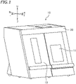
- FIG. 1 is a perspective view of a cutting machine 10 according to a preferred embodiment of the present invention.
- the direction away from the cutting machine 10 will be referred to as forward, and the direction toward the cutting machine 10 will be referred to as rearward.
- Left, right, up, and down refer to left, right, up, and down, respectively, when the cutting machine 10 is seen from the front.
- Characters F, Rr, L, R, U, and D in the drawings represent front, rear, left, right, up, and down, respectively.
- the cutting machine 10 is a cutting machine for cutting a disc-shaped cutting object retained by an adaptor.
- FIG. 2 is a plan view of a cutting object 1 and an adaptor 5.
- the cutting machine 10 herein is a machine for cutting the cutting object 1 to produce dental shaped products including crown prosthetics, such as a crown, a bridge, a coping, an inlay, an onlay, a veneer, and a custom abutment, artificial teeth, a denture base, and so forth.
- the cutting object 1 is made of, for example, a resin such as PMMA, PEEK, a glass fiber reinforced resin, or a hybrid resin, a ceramic material such as glass ceramic or zirconia, a metal material such as a cobalt-chrome sintered metal, wax, gypsum, or the like.
- a resin such as PMMA, PEEK, a glass fiber reinforced resin, or a hybrid resin
- a ceramic material such as glass ceramic or zirconia
- a metal material such as a cobalt-chrome sintered metal, wax, gypsum, or the like.
- zirconia as a material for the cutting object 1
- semi-sintered zirconia is used, for example.
- the cutting object 1 has a disc (circular plate) shape in this preferred embodiment.
- the cutting object 1 may have any other shapes, such as a block shape (e.g., a cube or a rectangular parallelepiped).
- the adaptor 5 retains the disc-shaped cutting object 1.
- the adaptor 5 herein is a flat-plate adaptor having an insertion hole 5a formed in a center portion of the adaptor 5.
- the insertion hole 5a has a circular or substantially circular shape corresponding to the cutting object 1.
- the cutting object 1 is inserted in the insertion hole 5a to be retained by the adaptor 5.
- the cutting object 1 is accommodated in the cutting machine 10 and processed while being retained by the adaptor 5.
- FIG. 3 is a perspective view illustrating the cutting machine 10 in a state where parts such as a case and a front cover are detached.
- the cutting machine 10 includes a processing chamber 11, an accommodation chamber 13, and a cleaning chamber 20.
- the processing chamber 11 is a space where the cutting object 1 is subjected to a cutting process.
- the processing chamber 11 is provided with a cutting device 12 for cutting the cutting object 1 retained by the adaptor 5.
- the accommodation chamber 13 is configured to accommodate a plurality of adaptors 5.
- the accommodation chamber 13 is a space for accommodating the plurality of cutting objects 1 retained by the adaptor 5 in order to continuously process the plurality of cutting objects 1.
- a cutting object 1 to be subjected to a cutting process is conveyed from the accommodation chamber 13 to the processing chamber 11, and after the cutting process, is returned to the accommodation chamber 13 by way of the cleaning chamber 20.
- the cutting machine 10 includes a conveyor 15 for conveying the adaptor 5 to the processing chamber 11, the cleaning chamber 20, and the accommodation chamber 13.
- the cleaning chamber 20 is provided with a cleaning device 40 (see FIG. 5 ) for cleaning the adaptor 5 retaining the cutting object 1 after the cutting process, and an adaptor moving device 50 (see FIG. 8 ) that moves the adaptor 5 in the left-right directions.
- the cutting device 12 may include, for example, a holder to hold the adaptor 5 retaining the cutting object 1, a rotation device to turn the orientation of the cutting object 1 by rotating the holder, a stocker for a cutting tool, a spindle to hold and rotate the cutting tool, and a moving device to move at least one of the rotation device or the spindle in the left-right directions, front-rear directions, and top-bottom directions.
- the cutting device 12 is not limited to a specific configuration.
- the accommodation chamber 13 is disposed at a side of the processing chamber 11, and in this preferred embodiment, at the left of the processing chamber 11.
- the accommodation chamber 13 extends in the top-bottom directions.
- the accommodation chamber 13 is provided with a plurality of adaptor containers 14 to accommodate the adaptors 5.
- the plurality of adaptor containers 14 extend in the top-bottom direction along the right wall of the accommodation chamber 13.
- the plurality of adaptor containers 14 include shelves extending in the top-bottom direction.
- Each of the adaptor containers 14 is configured such that the adaptor 5 supported horizontally or substantially horizontally can be placed on the adaptor container 14.
- the accommodation chamber 13 is provided with the conveyor 15.
- the conveyor 15 is disposed at the left of the plurality of adaptor containers 14.
- the conveyor 15 includes a clamp 16, a clamp accommodation part 17, and a lifting mechanism 18.
- the clamp 16 has a claw shape and is capable of holding the adaptor 5.
- the clamp 16 extends horizontally.
- the clamp accommodation part 17 is disposed at the left of the adaptor containers 14, and is configured to move upward and downward by driving of the lifting mechanism 18.
- the clamp accommodation part 17 has a box shape capable of accommodating the clamp 16. While the clamp accommodation part 17 moves upward and downward, the clamp 16 is accommodated in the clamp accommodation part 17. When the clamp accommodation part 17 stops at a side of one of the adaptor containers 14 and transfers the adaptor 5 to or from this adaptor container 14, the clamp 16 moves rightward from the inside of the clamp accommodation part 17.
- the clamp 16 enters the adaptor container 14.
- the clamp accommodation part 17 includes an unillustrated driver for the clamp 16.
- the lifting mechanism 18 in this preferred embodiment includes a guide rail 18a extending upward and downward, an unillustrated ball screw, and an unillustrated motor for rotating the ball screw.
- the conveyor 15 is not limited to a specific configuration.
- the conveyor 15 is configured to move the clamp accommodation part 17 to a position below the plurality of adaptor containers 14.
- the conveyor 15 transfers the adaptor 5 to and from the holder of the cutting device 12 located below the adaptor containers 14.
- the conveyor 15 is capable of moving the clamp accommodation part 17 to a position above the plurality of adaptor containers 14.
- the conveyor 15 transfers the adaptor 5 to and from a retainer 50A (see FIG. 8 ) of the adaptor moving device 50 located above the adaptor containers 14.
- FIG. 3 the cleaning chamber 20 is disposed above the processing chamber 11.
- the cleaning chamber 20 is located at the right of the accommodation chamber 13.
- FIG. 4 is a perspective view of the cleaning chamber 20.
- the cleaning chamber 20 can be detached from the cutting machine 10 as a unit as illustrated in FIG. 4 .
- FIG. 5 is a plan view of the cleaning chamber 20.
- FIG. 6 is a longitudinal cross-sectional view of the cleaning chamber 20 when seen from the rear.
- the outer shape of the cleaning chamber 20 is defined by a box-shaped housing 21.
- the housing 21 has a rectangular or substantially rectangular parallelepiped shape, and includes an upper wall 21U, a lower wall 21D, a front wall 21F, a rear wall 21Rr, a left wall 21L, and a right wall 21R.
- the upper wall 21U extends in the left-right directions and in the front-rear directions.
- the lower wall 21D is opposed to the upper wall 21U below the upper wall 21U.
- the lower wall 21D also extends in the left-right directions and in the front-rear directions.
- the front wall 21F is connected to the front end of the upper wall 21U and the front end of the lower wall 21D.
- the front wall 21F extends in the left-right directions and in the top-bottom directions.
- the rear wall 21Rr is connected to the rear end of the upper wall 21U and the rear end of the lower wall 21D.
- the rear wall 21Rr extends in the left-right directions and in the top-bottom directions.
- the front wall 21F is opposed to the rear wall 21Rr.
- the left wall 21L is connected to the left end of each of the upper wall 21U, the lower wall 21D, the front wall 21F, and the rear wall 21Rr, and extends in the front-rear directions and in the top-bottom directions.
- the right wall 21R is connected to the right end of each of the upper wall 21U, the lower wall 21D, the front wall 21F, and the rear wall 21Rr, and extends in the front-rear directions and in the top-bottom directions.
- the left wall 21L is opposed to the right wall 21R.
- These walls 21U, 21D, 21F, 21Rr, 21L, and 21R of the housing 21 form internal space 21a of the housing 21.
- the cleaning device 40 is accommodated in the internal space 21a of the housing 21.
- an entrance 22 for the adaptor 5 is formed in the left wall 21L of the housing 21.
- the entrance 22 is open in the left-right directions, and extends in the front-rear directions and in the top-bottom directions.
- the adaptor 5 is moved in the opening directions of the entrance 22 (i.e., in the directions in which the entrance 22 faces, that is, in the left-right directions in this preferred embodiment) to move in or out of the housing 21.
- the adaptor 5 is moved in the left-right directions by the adaptor moving device 50 described later.
- the entire left end surface of the wall of the housing 21 may be open as the entrance 22 for the adaptor 5.
- the housing 21 may have substantially no left wall 21L.
- the entrance 22 is provided with a door 30.
- the door 30 is configured to pivot in the left-right directions by hinges 30a connected to the upper end of the door 30.
- the hinges 30a include pivot shafts 30b extending in the front-rear directions.
- the door 30 is opened and closed by pivoting about the pivot shafts 30b in the left-right directions.
- a stopper 21L1 is provided at the right of the door 30, that is, at the side toward the internal space 21a of the housing 21.
- the stopper 21L1 restricts a pivot of the door 30.
- the stopper 21L1 restricts entering of the door 30 into the housing 21. In other words, the door 30 is pivotable outside the housing 21.
- FIGS. 4 and 6 illustrate the cleaning chamber 20 with the door 30 closed.
- FIG. 5 illustrates the cleaning chamber 20 with the door 30 open.
- An outlet 23 to which an exhaust device M1a (see FIG. 10 ) is connected is formed in the lower wall 21D.
- the exhaust device M1a in this preferred embodiment is a dust collector to collect cutting powder generated by a cutting process of the cutting object 1.
- the outlet 23 is open at the lower wall 21D to intersect with the opening directions (the left-right directions in this preferred embodiment) of the entrance 22.
- the outlet 23 is open in the top-bottom directions in this preferred embodiment.
- the outlet 23 includes a plurality of slit through holes. With respect to the left-right directions, the outlet 23 is located at the right of the left end (an end toward the entrance 22) of the cleaning device 40. In other words, the outlet 23 is farther from the entrance 22 than the end of the cleaning device 40 toward the entrance 22. In this preferred embodiment, the outlet 23 is provided immediately under the cleaning device 40.
- a first inlet 24 is formed in the upper wall 21U to face the outlet 23 when seen in the opening directions of the entrance 22 (in the left-right directions in this preferred embodiment).
- the first inlet 24 is open in the top-bottom directions.
- the first inlet 24 and second inlets 26 described later are openings for generating an air flow toward the outlet 23 in the internal space 21a of the housing 21.
- the first inlet 24 and the second inlets 26 are openings for preventing the internal space 21a of the housing 21 from being under a significantly negative pressure.
- the first inlet 24 is disposed at the right of the entrance 22 and at the left of the cleaning device 40 in plan view.
- the first inlet 24 is located closer to the entrance 22 than the cleaning device 40 in the opening directions of the entrance 22 (in the left-right directions in this preferred embodiment).
- the first inlet 24 has a rectangular or substantially rectangular shape in plan view.
- the first inlet 24 is a flat rectangle that is long in the front-rear directions and short in the left-right directions.
- the first inlet 24 is provided with a shutter 31.
- the opening area of the first inlet 24 increases or decreases by opening or closing the shutter 31.
- the shutter 31 has a flat plate shape extending in the left-right directions and in the front-rear directions.
- the shutter 31 is movable in the left-right directions.
- the shutter 31 is coupled to a coupling member 58, and moves rightward when the coupling member 58 is pushed rightward. This rightward movement of the shutter 31 reduces the opening area of the first inlet 24.
- FIG. 7 is a plan view illustrating the cleaning chamber 20 in a state where the shutter 31 is closed to the most. As illustrated in FIG. 7 , the shutter 31 closed to the most fully closes the first inlet 24.
- a device to push the coupling member 58 rightward is the adaptor moving device 50 to move the adaptor 5 in the left-right directions in this preferred embodiment. That is, the shutter opening/closing device to change the opening area of the first inlet 24 by opening and closing the shutter 31 is shared by the adaptor moving device 50. When there is no force of pushing the coupling member 58 rightward any more, the shutter 31 moves leftward by a restoring force of a spring 32 connected to the left edge.
- the upper wall 21U further has a work window 25.
- the work window 25 is open in the top-bottom directions.
- the work window 25 is an opening for allowing a user to perform a work in the housing 21 (e.g., a work of collecting the adaptor 5 dropped in the housing because of improper mounting).
- a gasket 25a to close the work window 25 is provided around the work window 25.
- an unillustrated lid is placed over the housing 21 in normal use. When the gasket 25a is crushed by the unillustrated lid so that the work window 25 is closed in normal use.
- the right wall 21R has a pair of second inlets 26 located in a front portion and a rear portion of the right wall 21R.
- Each of the second inlets 26 is open in the left-right directions.
- the second inlets 26 are disposed at the opposite side to the first inlet 24 with respect to the outlet 23.
- the outlet 23 is disposed between the first inlet 24 and the second inlets 26.
- the second inlets 26 are disposed below the cleaning device 40.
- the positions of the second inlets 26 are not limited.
- the first inlet 24 is disposed above the cleaning device 40.
- the second inlets 26 are preferably disposed to face a portion in the internal space 21a of the housing 21 where an air flow is less likely to occur in an airflow from the first inlet 24 and the outlet 23.
- the second inlets 26 are flat slit through holes that are long in the front-rear directions and short in the top-bottom directions.
- the opening area of each of the second inlets 26 is smaller than the opening area of the first inlet 24 in the state where the shutter 31 is fully open.
- the total opening area of the plurality of second inlets 26 is smaller than the opening area of the first inlet 24 in the state where the shutter 31 is fully open.
- the second inlets 26 are not limited to a specific shape and a specific size.
- the adaptor moving device 50 transfers the adaptor 5 to and from the conveyor 15, and changes the position of the adaptor 5 in the cleaning chamber 20 during cleaning of the adaptor 5.
- the adaptor moving device 50 in this preferred embodiment moves the adaptor 5 in the left-right directions inside and outside the cleaning chamber 20.
- the adaptor moving device 50 is also the driver to open and close the shutter 31 as described above.
- FIG. 8 is a perspective view of the adaptor moving device 50 when seen from the internal space 21a of the housing 21. As illustrated in FIGS. 4 and 8 , the adaptor moving device 50 includes the retainer 50A to retain the adaptor 5, and a driver 50B to move the retainer 50A in the left-right directions.
- the retainer 50A includes a mounting part 51 and a support plate 52.
- the mounting part 51 has a U shape that is open to the left.
- the mounting part 51 includes a first retention arm 51a and a second retention arm 51b each extending leftward from the root of the U shape.
- the second retention arm 51b is located forward of the first retention arm 51a.
- the adaptor 5 is attached between the first retention arm 51a and the second retention arm 51b.
- the adaptor 5 is retained in a horizontal or substantially horizontal orientation by the retainer 50A. In the following description, as illustrated in FIGS.
- the surface of the adaptor 5 facing upward while the adaptor 5 is retained by the retainer 50A will be referred to as an upper surface 5U, and the surface facing downward will be referred to as a lower surface 5D.
- an upper surface 5U the surface facing upward while the adaptor 5 is retained by the retainer 50A
- the surface facing downward will be referred to as a lower surface 5D.
- the upper surface 5U and the lower surface 5D of the adaptor 5 as an object may be the same.
- the support plate 52 extends in the left-right directions and in the top-bottom directions.
- the support plate 52 extends along the surface (rear surface) of the front wall 21F of the housing 21 toward the internal space 21a.
- the support plate 52 is coupled to the driver 50B, and supports the mounting part 51.
- the support plate 52 projects to the left of the mounting part 51, that is, toward the accommodation chamber 13.
- the left end of the support plate 52 is provided with a first washer 52a.
- a portion of the front end of the support plate 52 above the first washer 52a includes a chamfer 52b.
- a second washer 52c is provided at the top of the chamfer 52b.
- each of the first washer 52a and the second washer 52c is made of a soft material, for example, a resin such as POM.
- the support plate 52 also has the function of reducing or preventing the scattering of dust by cleaning toward the driver 50B.
- the driver 50B includes a driving motor 53, a pair of guide shafts 54, a slide block 55, a ball screw 56, and a nut 57.
- the pair of guide shafts 54 is disposed side by side in the top-bottom directions, and extends in the left-right directions.
- the slide block 55 is engaged with the pair of guide shafts 54 to be slidable in the left-right directions.
- the nut 57 is fixed to the slide block 55.
- the ball screw 56 is meshed with the nut 57.
- the ball screw 56 extends in the left-right directions.
- the driving motor 53 is coupled to the ball screw 56, and rotates the ball screw 56 about the axis. Accordingly, the slide block 55 travels along the guide shafts 54.
- the slide block 55 is coupled to the support plate 52 of the retainer 50A through a slit 21F1 provided in the front wall 21F. Then, when the driving motor 53 is driven, the retainer 50A moves in the left-right directions.
- the adaptor moving device 50 moves the retainer 50A by the driver 50B to move the adaptor 5 in the left-right directions.
- the driving motor 53 in this preferred embodiment is a motor capable of detecting the amount of rotation, and a travel distance of the retainer 50A is detected by the driving motor 53.
- the coupling member 58 couples the shutter 31 and the retainer 50A to each other to link movement of the shutter 31 and movement of the adaptor 5 to each other.
- the coupling member 58 couples the shutter 31 and the retainer 50A to each other through the slide block 55.
- the left end of the coupling member 58 is connected to the shutter 31.
- the right end of the coupling member 58 is provided with a contact part 58a that is pushed by the slide block 55.
- the contact part 58a is disposed on a moving path of the slide block 55.
- the adaptor moving device 50 When the adaptor moving device 50 is driven so that the slide block 55 moves rightward, the slide block 55 and the contact part 58a that was not in contact with each other originally are brought into contact with each other. Then, when the slide block 55 continues to move rightward, the coupling member 58 moves rightward, and the shutter 31 is gradually closed. That is, the shutter 31 starts being closed from a state where the adaptor 5 is inserted in the housing 21 to a certain degree, and as the adaptor 5 further moves into the housing 21 (rightward in this preferred embodiment), the shutter 31 is gradually closed. In other words, as the adaptor 5 moves to the depth of the housing 21, the opening area of the first inlet 24 decreases.
- the adaptor moving device 50 as the shutter opening/closing device performs both movement of the adaptor 5 retained by the retainer 50A and opening/closing of the shutter 31 by the coupling member 58.
- the shutter 31 and the coupling member 58 may be one integrated unitary structure.
- a limit switch 59 is provided at the right end of the moving path of the slide block 55.
- the slide block 55 moves rightward, the slide block 55 is brought into contact with an arm 59a of the limit switch 59, and the limit switch 59 turns on. Accordingly, it is detected that the adaptor 5 has reached the right end.
- the cleaning device 40 cleans the adaptor 5 retained by the retainer 50A of the adaptor moving device 50 in the internal space 21a of the housing 21.
- the cleaning device 40 includes a first pivot arm 41, a second pivot arm 42, a pivot shaft 43 of the first pivot arm 41 and the second pivot arm 42, and an actuator 44 for causing the first pivot arm 41 and the second pivot arm 42 to pivot about the pivot shaft 43.
- the first pivot arm 41 is provided with a first nozzle 41N that injects compressed air to the upper surface 5U of the adaptor 5.
- the second pivot arm 42 is provided with a second nozzle 42N that injects compressed air to the lower surface 5D of the adaptor 5. Compressed air is supplied from an external air compressor M2 described later (see FIG. 10 ).
- the pivot shaft 43 extends in the top-bottom directions.
- the first pivot arm 41 is fixed to the pivot shaft 43, and disposed above the adaptor 5 retained by the retainer 50A.
- the first nozzle 41N supported by the first pivot arm 41 is also disposed above the adaptor 5 retained by the retainer 50A.
- the cleaning device 40 only needs to be configured such that the first nozzle 41N is located above the adaptor 5 retained by the retainer 50A, and the position of the first pivot arm 41 in the top-bottom directions is not limited to a position above the adaptor 5.
- the first pivot arm 41 may be partially located above the adaptor 5.
- the first nozzle 41N is open downward. The first nozzle 41N injects compressed air downward.
- the second pivot arm 42 is located below the adaptor 5 retained by the retainer 50A.
- the second pivot arm 42 is also fixed to the pivot shaft 43.
- the second nozzle 42N supported by the second pivot arm 42 is also disposed below the adaptor 5 retained by the retainer 50A.
- the cleaning device 40 only needs to be configured such that the second nozzle 42N is located below the adaptor 5 retained by the retainer 50A, and the position of the second pivot arm 42 in the top-bottom directions is not limited to a position below the adaptor 5.
- the second nozzle 42N is open upward.
- the second nozzle 42N injects compressed air upward.
- the first pivot arm 41 and the second pivot arm 42 overlap each other in plan view.
- the first pivot arm 41 and the second pivot arm 42 extend in the same direction from the common pivot shaft 43 in plan view.
- the positions of the first nozzle 41N and the second nozzle 42N are shifted in plan view.
- the positions of the first nozzle 41N and the second nozzle 42N are shifted in the directions in which the adaptor 5 is moved by the adaptor moving device 50, which is in the left-right directions in this preferred embodiment. More specifically, the first nozzle 41N and the second nozzle 42N are located at different distances from the pivot shaft 43. In this preferred embodiment, as illustrated in FIG.
- the cleaning device 40 is configured such that the distance between the first nozzle 41N and the pivot shaft 43 is longer than the distance between the second nozzle 42N and the pivot shaft 43.
- the distance between the second nozzle 42N and the pivot shaft 43 may be longer than the distance of the first nozzle 41N from the pivot shaft 43.
- the first pivot arm 41 is separated from the upper wall 21U.
- the first pivot arm 41 is disposed below the upper wall 21U.
- a gap is present between the first pivot arm 41 and the upper wall 21U.
- the second pivot arm 42 is separated from the lower wall 21D.
- the second pivot arm 42 is disposed above the lower wall 21D.
- a gap is present between the second pivot arm 42 and the lower wall 21D. Consequently, a gap is present between the cleaning device 40 and the outlet 23.
- the gap between the cleaning device 40 and the wall of the housing 21 in the top-bottom directions is a channel in which air sucked from the first inlet 24 flows to the outlet 23, which will be described later.
- FIG. 9 is a plan view illustrating the cleaning chamber 20 while the first pivot arm 41 and the second pivot arm 42 are pivoting. As illustrated in FIG. 9 , both the first pivot arm 41 and the second pivot arm 42 are fixed to the pivot shaft 43 that pivots about the axis, and pivot in synchronization with each other. While pivoting, the first pivot arm 41 and the second pivot arm 42 overlap each other in plan view.
- the actuator 44 causes the pivot shaft 43 to pivot about the axis to cause the first pivot arm 41 and the second pivot arm 42 to pivot about the pivot shaft 43.
- the actuator 44 is not limited to a specific type, and an electric motor in this preferred embodiment. As illustrated in FIG.
- a gear 44a is provided to the rotation shaft of the actuator 44.
- the gear 44a meshes with the gear 43a provided to the pivot shaft 43.
- the gear 44a rotates so that the gear 43a and the pivot shaft 43 rotate.
- a detection plate 45 is provided on the pivot shaft 43.
- the detection plate 45 is a flat-plate member and extends horizontally. As illustrated in FIG. 9 , the detection plate 45 pivots together with the pivot shaft 43.
- a limit switch 46 is provided on a pivot path of the detection plate 45. When the pivot shaft 43 rotates clockwise when seen from above, the detection plate 45 is brought into contact with the arm 46a of the limit switch 46. Accordingly, the limit switch 46 turns on.
- the limit switch 46 is a sensor to detect pivot origins of the first pivot arm 41 and the second pivot arm 42. When the limit switch 46 detects the pivot origins of the first pivot arm 41 and the second pivot arm 42, the actuator 44 changes the rotation direction such that the pivot shaft 43 rotates counterclockwise when seen from above.
- the actuator 44 When the actuator 44 causes the first pivot arm 41 and the second pivot arm 42 to pivot by a predetermined pivot angle, the actuator 44 changes the rotation direction again.
- the actuator 44 is, for example, a motor including an encoder and capable of measuring a rotation angle. By repeating the operation of changing the pivot direction described above, the first pivot arm 41 and the second pivot arm 42 pivot about the pivot shaft 43 back and forth.
- the method for causing the first pivot arm 41 and the second pivot arm 42 to pivot back and forth is not limited to the method described above.
- FIG. 10 is a system diagram showing emission of air in the housing 21 and supply of compressed air.
- the outlet 23 of the cleaning chamber 20 is connected to the exhaust device (dust collector) M1a.
- the exhaust device M1a sucks dust generated by cutting of the cutting object 1 and adhering to the adaptor 5 and the cutting object 1, together with air in the housing 21.
- two exhaust devices are connected to the cutting machine 10.
- another exhaust device M1b is connected to the processing chamber 11.
- a common exhaust device may be connected to the cleaning chamber 20 and the processing chamber 11.
- the cleaning device 40 includes an air circuit 60 connected to the air compressor M2.
- the cutting machine 10 may also include a nozzle to inject compressed air to a place except the cleaning chamber 20, such as the processing chamber 11, and may include an air circuit to supply compressed air to this place.
- the air circuit 60 includes an air channel 61 and a channel switching member 62.
- the air channel 61 includes an inlet channel 61a, and a first channel 61b and a second channel 61c branched from the inlet channel 61a.
- One end of the inlet channel 61a is connected to the air compressor M2.
- the end of the inlet channel 61a connected to the air compressor M2 defines an air supply port 61d to which compressed air is supplied from the air compressor M2.
- the first channel 61b and the second channel 61c are respectively connected to the first nozzle 41N and the second nozzle 42N.
- the channel switching member 62 is disposed in the air channel 61, and causes the air supply port 61d to selectively communicate with the first nozzle 41N or the second nozzle 42N.
- the channel switching member 62 in this preferred embodiment includes a first valve 62a provided in the first channel 61b, and a second valve 62b provided in the second channel 61c.
- the first valve 62a and the second valve 62b are electromagnetic valves in this preferred embodiment.
- the first valve 62a is opened during injection of compressed air from the first nozzle 41N. At this time, the second valve 62b is closed. During injection of compressed air from the second nozzle 42N, the second valve 62b is opened. At this time, the first valve 62a is closed.
- the channel switching member 62 is not limited to the configuration described above.
- the channel switching member 62 may be a valve disposed at a branch point among the inlet channel 61a, the first channel 61b, and the second channel 61c and capable of switching the position between a first position in which the inlet channel 61a and the first channel 61b communicate with each other and a second position in which the inlet channel 61a and the second channel 61c communicate with each other.
- an opening/closing valve may be provided in the inlet channel 61a, for example.
- FIG. 11 is a block diagram of the cutting machine 10.
- the cutting machine 10 includes the controller 100 configured or programmed to control operation of each component.
- the controller 100 is connected to the cutting device 12, the clamp accommodation part 17 and the lifting mechanism 18 of the conveyor 15, the actuator 44, the first valve 62a, and the second valve 62b of the cleaning device 40, the driving motor 53 of the adaptor moving device 50, the exhaust device M1a of the cleaning chamber 20, and the exhaust device M1b of the processing chamber 11.
- the controller 100 is configured or programmed to control operation of these components.
- the controller 100 is also connected to the limit switch 46 of the cleaning device 40 and the limit switch 59 of the adaptor moving device 50, and receives signals from these limit switches.
- the controller 100 may be connected to other members such as other limit switches, and illustration and description thereof will be omitted.
- the controller 100 is not limited to a specific configuration.
- the controller 100 may include, for example, a central processing unit (hereinafter referred to as a CPU), a ROM to store, for example, a program to be executed by the CPU, a RAM, and so forth.
- a CPU central processing unit
- ROM read-only memory
- Each component of the controller 100 may be software or hardware.
- Each component may be a processor or a circuit.
- the controller 100 is configured or programmed to include a cutting controller 110, a conveyance controller 120, a cleaning controller 130, and a movement controller 140.
- the controller 100 may include other processing sections, and illustration and description thereof will be omitted.
- the cutting controller 110 controls the cutting device 12 to cut the cutting object 1, and processes the cutting object 1 into a shape based on input cutting data. Although specifically described later, the cutting controller 110 is configured or programmed to enable cutting of another cutting object 1 during cleaning of the adaptor 5.
- the conveyance controller 120 controls the conveyor 15 to convey the adaptor 5 to the processing chamber 11, the accommodation chamber 13, and the cleaning chamber 20. As illustrated in FIG. 11 , the conveyance controller 120 includes a first conveyance controller 121, a second conveyance controller 122, and a third conveyance controller 123. After cutting of the cutting object 1 has been finished, the first conveyance controller 121 controls the conveyor 15 to convey the adaptor 5 in the processing chamber 11 to the cleaning chamber 20. After cleaning of the adaptor 5 has been finished, the second conveyance controller 122 controls the conveyor 15 to convey the adaptor 5 in the cleaning chamber 20 to the accommodation chamber 13. The third conveyance controller 123 controls the conveyor 15 to convey the selected adaptor 5 from the accommodation chamber 13 to the processing chamber 11. The selected adaptor 5 is an adaptor 5 retaining a cutting object 1 to be cut.
- the cleaning controller 130 includes a first cleaning controller 131 and a second cleaning controller 132.
- the first cleaning controller 131 controls the cleaning device 40 to clean the adaptor 5 in the cleaning chamber 20.
- the first cleaning controller 131 controls the first valve 62a and the second valve 62b, and causes the first nozzle 41N or the second nozzle 42N to inject compressed air.
- the order of injecting compressed air from the first nozzle 41N or the second nozzle 42N is registered beforehand.
- the first cleaning controller 131 is set such that the second nozzle 42N injects compressed air and then the first nozzle 41N injects compressed air.
- the first cleaning controller 131 injects air upward to clean the adaptor 5 and then injects air downward to clean the adaptor 5.
- the first cleaning controller 131 controls the actuator 44 to cause the first pivot arm 41 and the second pivot arm 42 to pivot.
- the first cleaning controller 131 drives the exhaust device M1a.
- the second cleaning controller 132 controls cleaning operation in the cleaning chamber 20 after cleaning of the adaptor 5 is finished and the adaptor 5 is conveyed from the cleaning chamber 20. After cleaning of the adaptor 5, the second cleaning controller 132 controls the cleaning device 40 and causes at least one of the first nozzle 41N or the second nozzle 42N to inject compressed air to clean the cleaning chamber 20. In cleaning in the cleaning chamber 20, the order of injecting compressed air from the first nozzle 41N or the second nozzle 42N is also registered beforehand. The order is not specifically limited, and may be similar to that during cleaning of the adaptor 5.
- the second cleaning controller 132 may be configured to drive the exhaust device M1a during cleaning in the cleaning chamber 20.
- the movement controller 140 controls operation of the adaptor moving device 50.
- the movement controller 140 moves the retainer 50A to the outside of the housing 21.
- the position of the retainer 50A at this time will be hereinafter referred to as a transfer position.
- the transfer position is the position of the retainer 50A illustrated in FIG. 5 .
- the movement controller 140 moves the retainer 50A between the right end (the deepest position of the housing 21 in the movable range, hereinafter referred to as a standby position) and a cleaning end position at a predetermined distance to the left from the standby position.
- the standby position is the position of the retainer 50A illustrated in FIG. 7 .
- the cleaning end position is set at a position at which the door 30 is not opened by the retainer 50A and the adaptor 5 is located at the left of the first nozzle 41N.
- the cleaning end position is located between the standby position and the transfer position in the left-right directions. Control of the adaptor moving device 50 by the movement controller 140 will be specifically described in description of a cleaning process.
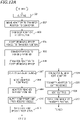
- FIGS. 12A and 12B show a flowchart depicting a process from cutting of the cutting object 1 to returning of the adaptor 5 to the accommodation chamber 13.
- FIG. 12A shows a first half of the flowchart.
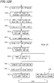
- FIG. 12B is a second half of the flowchart.
- description starts from step S01 in which the cutting object 1 is subjected to a cutting process in the processing chamber 11.
- step S02 the adaptor 5 retaining the cutting object 1 after the cutting process is moved to a transfer position to the conveyor 15 by the moving device of the cutting device 12.
- step S03 the conveyor 15 receives the adaptor 5 retaining the cutting object 1 after the cutting process from the cutting device 12. At this time, cutting powder generated by the cutting process of the cutting object 1 adheres to the adaptor 5 and the cutting object 1.
- step S04 the adaptor moving device 50 moves the retainer 50A from the standby position to the transfer position. While the retainer 50A is at the standby position, the shutter 31 is fully closed as illustrated in FIG. 7 . While the retainer 50A is at the standby position, the door 30 is closed.
- the retainer 50A moves to the transfer position, as illustrated in FIG. 5 , pushing of the coupling member 58 by the retainer 50A is released so that the shutter 31 is opened.
- the retainer 50A pushes the door 30 so that the door 30 is opened toward outside of the housing 21.
- FIG. 13 is a perspective view illustrating the retainer 50A and the door 30 while the retainer 50A is at the transfer position.
- the second washer 52c of the retainer 50A supports the door 30 in an open state.
- an intermediate state is not shown, when the retainer 50A is moved leftward, the first washer 52a is first brought into contact with the door 30 and opens the door 30 by pushing. Thereafter, the retainer 50A is further moved leftward, and when the door 30 is further opened, a portion supporting the door 30 changes from the first washer 52a to the second washer 52c.
- step S05 the conveyor 15 is moved upward, and is located at the transfer position of the adaptor 5 to the adaptor moving device 50.
- step S06 the adaptor 5 is transferred from the conveyor 15 to the adaptor moving device 50.
- the adaptor moving device 50 is configured such that the retainer 50A moves between the inside and outside of the cleaning chamber 20 through the entrance 22 of the adaptor 5 and transfers the adaptor 5 to and from the conveyor 15.
- step S06 the cleaning device 40 and the adaptor moving device 50 operate separately from and simultaneously with the conveyor 15 and the cutting device 12.
- steps concerning operation of the cleaning device 40 and the adaptor moving device 50 and steps concerning operation of the conveyor 15 and the cutting device 12 will be illustrated in different systems.
- the order of steps S02 through S06 may be changed if possible.
- step S07 the exhaust device M1a is driven. Thus, air is discharged from the outlet 23. Accordingly, outside air starts flowing into the housing 21 from the first inlet 24 and the pair of second inlets 26.
- step S08 the adaptor 5 retained by the retainer 50A is moved to the depth of the housing 21, that is, to the right in this preferred embodiment. The movement of the retainer 50A causes the door 30 to be closed. The door 30 is opened when being pushed leftward by the retainer 50A moved by the driver 50B, and is closed by the self-weight in the absence of support by the retainer 50A.
- the controller 100 controls the cleaning device 40 to clean the adaptor 5, and during cleaning of the adaptor 5, controls the adaptor moving device 50 as the opening/closing device of the door 30 to close the door 30.
- the cutting machine 10 may include an opening/closing device of the door 30 independent of the adaptor moving device 50.
- the opening area of the first inlet 24 is at maximum to this time. While the opening area of the first inlet 24 is at maximum, a large portion of air flowing into the housing 21 is air flowing from the first inlet 24.
- the opening area of the pair of second inlets 26 is considerably smaller than the opening area of the first inlet 24 while the shutter 31 is fully open. Thus, while the opening area of the first inlet 24 is at maximum, the amount of air flowing from the second inlets 26 is small.
- the controller 100 controls the adaptor moving device 50 as the moving device of the adaptor 5 and the opening/closing device of the shutter 31 to open and close the shutter 31 and move the adaptor 5, while controlling the cleaning device 40 to clean the adaptor 5.
- the opening area of the first inlet 24 gradually decreases by gradual closing of the shutter 31, the amount of air flowing from the first inlet 24 gradually decreases, and the amount of air flowing from the second inlets 26 gradually increases.
- the opening area of the first inlet 24 (except for a gap between the first inlet 24 and the shutter 31) becomes zero, and a major portion of the air flowing into the housing 21 is air flowing from the pair of second inlets 26.
- Advantages obtained by the change in intake air amount balance between the first inlet 24 and the second inlets 26 will be described later.
- step S09 the retainer 50A reaches the standby position at the right end of the movable range.
- the limit switch 59 detects that the retainer 50A has reached the standby position.
- step S10 the second valve 62b is opened, and compressed air is injected from the second nozzle 42N. Accordingly, compressed air is injected upward. Compressed air injected upward from the second nozzle 42N is blown to the lower surface 5D of the adaptor 5.
- step S11 pivot of the first pivot arm 41 and the second pivot arm 42 starts.
- step S12 the retainer 50A is moved leftward. The injection of compressed air, the pivot of the first pivot arm 41 and the second pivot arm 42, and the movement of the retainer 50A cause cleaning of the adaptor 5 to start substantially.
- each of the pivot of the first pivot arm 41 and the second pivot arm 42 and the movement of the retainer 50A is intermittently performed.
- steps S11 and S12 first, the first pivot arm 41 and the second pivot arm 42 pivot from the origin by a predetermined angle. The pivot direction at this time is counterclockwise when seen from above.
- the retainer 50A is moved leftward to a predetermined distance (e.g., about 1 mm to about 5 mm). Thereafter, the first pivot arm 41 and the second pivot arm 42 rotate in the opposite direction, and return to the origin.
- the second nozzle 42N moves in the pivot direction of the second pivot arm 42, and the adaptor 5 moves in a direction (leftward in this preferred embodiment) intersecting with the pivot direction of the second pivot arm 42 so that compressed air from the second nozzle 42N is sequentially blown to the entire lower surface 5D of the adaptor 5. Accordingly, the entire lower surface 5D of the adaptor 5 is sequentially cleaned.
- the operation of the cleaning device 40 and the adaptor moving device 50 described above is merely a preferred example, and operation of the cleaning device 40 and the adaptor moving device 50 in cleaning of the adaptor 5 is not limited.
- the adaptor moving device 50 may continuously move the retainer 50A in the left-right directions.
- step S13 the retainer 50A reaches the cleaning end position.
- the driving motor 53 detects that the retainer 50A has reached the cleaning end position.
- the moving direction of the retainer 50A and the nozzle that injects compressed air change.
- step S14 the nozzle that injects compressed air is switched from the second nozzle 42N to the first nozzle 41N. Accordingly, the direction of compressed air changes to the downward direction.
- step S15 the moving direction of the retainer 50A and the adaptor 5 changes to the right.
- the first nozzle 41N moves in the pivot direction of the first pivot arm 41 and the adaptor 5 moves in the direction (rightward in this preferred embodiment) intersecting with the pivot direction of the first pivot arm 41 so that compressed air from the first nozzle 41N is sequentially blown to the entire upper surface 5U of the adaptor 5. Accordingly, the entire upper surface 5U of the adaptor 5 is sequentially cleaned.
- step S16 the retainer 50A reaches the standby position. At this time, the first pivot arm 41 and the second pivot arm 42 are located at the origin. In subsequent step S17, the first valve 62a is closed, and injection of compressed air from the first nozzle 41N stops. The pivot of the first pivot arm 41 and the second pivot arm 42 stops at this time. In this manner, cleaning of the adaptor 5 is finished.
- step S18 the retainer 50A is moved leftward again.
- the leftward movement causes the retainer 50A to reach the transfer position in step S19.
- the door 30 is opened.
- step S20 the adaptor 5 subjected to cleaning is transferred to the conveyor 15.
- step S22 the retainer 50A moves rightward to the standby position again.
- step S23 when it is detected that the retainer 50A has reached the standby position, the steps concerning operation of the cleaning device 40 and the adaptor moving device 50 are finished.
- cleaning of the cleaning chamber 20 may be started (not shown).
- compressed air may be injected sequentially from at least one of the first nozzle 41N or the second nozzle 42N or from the first nozzle 41N and the second nozzle 42N, and the first pivot arm 41 and the second pivot arm 42 may pivot back and forth.
- the exhaust device M1a may be driven.
- step S24 following step S06, the conveyor 15 moves to the side of the adaptor containers 14 accommodating the adaptor 5 retaining a cutting object 1 to be next cut, and holds the adaptor 5.
- step S25 the next adaptor 5 is transferred from the conveyor 15 to the cutting device 12.
- step S26 the next cutting object 1 is subjected to a cutting process by the cutting device 12. At this time, in the cleaning chamber 20, cleaning is performed on the adaptor 5 retaining the cutting object 1 after the cutting process.
- the cutting machine 10 is capable of cutting another cutting object 1 during cleaning of the adaptor 5. If a cutting object 1 to be next processed is not set, steps S24 through S26 are omitted.
- step S27 the conveyor 15 moves to the transfer position of the adaptor 5 to the adaptor moving device 50.
- step S27 is followed by step S20, and the adaptor 5 after cleaning is transferred to the conveyor 15.
- step S28 for the conveyor 15 the adaptor 5 after cleaning is returned to the adaptor containers 14 by the conveyor 15. Accordingly, the steps concerning the conveyor 15 and the cutting device 12 are finished.
- the cutting machine 10 includes the processing chamber 11 provided with the cutting device 12 to cut the cutting object 1 retained by the adaptor 5, the cleaning chamber 20 provided with the cleaning device 40 to clean the adaptor 5, and the conveyor 15 to convey the adaptor 5 to the processing chamber 11 and the cleaning chamber 20.
- cleaning of an adaptor and a cutting object after a cutting process is performed in a processing chamber or manually performed outside the cutting machine.
- the time for the cutting process includes the cleaning time of the adaptor 5, and thus, the time for the cutting process is long.
- a user is under a load of cleaning the adaptor.
- the cutting machine 10 includes the cleaning chamber 20 to clean the adaptor 5 provided as a separate structure from the processing chamber 11, and the conveyor 15 to convey the adaptor 5 to the processing chamber 11 and the cleaning chamber 20.
- the adaptor 5 retaining the cutting object 1 after the cutting process is conveyed to the cleaning chamber 20 so that the next cutting object 1 can be processed without waiting for cleaning of the adaptor 5. Accordingly, the time for a cutting process on the cutting object 1 can be reduced.
- cleaning of the adaptor 5 is performed by the cleaning device 40 provided in the cleaning chamber 20, a load on a user can be reduced, unlike manual cleaning of the adaptor.
- the cutting machine 10 includes the accommodation chamber 13 capable of accommodating the plurality of adaptors 5, and the controller 100 to control automatic cleaning of the adaptor 5 retaining the cutting object 1 after cutting.
- the cutting machine 10 controls the conveyor 15 to convey the adaptor 5 in the processing chamber 11 to the cleaning chamber 20.
- the cutting machine 10 further controls the cleaning device 40 to clean the adaptor 5 in the cleaning chamber 20.
- the cutting machine 10 controls the conveyor 15 to convey the adaptor 5 in the cleaning chamber 20 to the accommodation chamber 13.
- the cutting machine 10 is capable of cutting another cutting object 1 during cleaning of the adaptor 5. With this configuration, another cutting object 1 can be processed without waiting for the end of cleaning of the adaptor 5. Thus, a throughput of a cutting process can be increased.
- the cleaning device 40 includes the first nozzle 41N and the second nozzle 42N that inject compressed air toward the adaptor 5. With this configuration, cleaning of the adaptor 5 can be easily performed by blowing compressed air.
- the cleaning device 40 has a configuration to shift the positions of the first nozzle 41N and the second nozzle 42N.
- the structure to shift the positions of the first nozzle 41N and the second nozzle 42N includes the first pivot arm 41, the second pivot arm 42, the pivot shaft 43, and the actuator 44 in this preferred embodiment. With this configuration, since the positions of the first nozzle 41N and the second nozzle 42N that inject compressed air are shifted, compressed air can be blown to various portions of the adaptor 5. Thus, cleaning can be more favorably performed on the adaptor 5.
- the structure to shift the positions of the nozzles is not specifically limited, and the advantages described above can be obtained by other configurations.
- the cutting machine 10 further includes the adaptor moving device 50 to change the position of the adaptor 5 in the cleaning chamber 20.
- the adaptor moving device 50 to change the position of the adaptor 5 in the cleaning chamber 20.
- the direction in which the adaptor moving device 50 moves the adaptor 5 and the direction in which the first nozzle 41N and the second nozzle 42N move intersect with each other.
- the pivot direction of the first pivot arm 41 and the second pivot arm 42 intersects with the direction in which the adaptor moving device 50 moves the adaptor 5.
- the first nozzle 41N is disposed above the adaptor 5 retained by the retainer 50A, and injects compressed air to the upper surface 5U of the adaptor 5 retained by the retainer 50A.
- the second nozzle 42N is disposed below the adaptor 5 retained by the retainer 50A, and injects compressed air to the lower surface 5D of the adaptor 5 retained by the retainer 50A.
- the positions of the first nozzle 41N and the second nozzle 42N are shifted from each other in plan view.
- the first nozzle 41N is preferably disposed above the adaptor 5 and open downward
- the second nozzle 42N is preferably disposed below the adaptor 5 and open upward.
- the position of the first nozzle 41N and the position of the second nozzle 42N are shifted or spaced from each other in plan view. With this configuration, the possibility of entering of dust blown by compressed air from one of the nozzles into the other nozzle can be reduced. Thus, the possibility of damage of, for example, the air circuit described above can be reduced or eliminated.
- the positions of the first nozzle 41N and the second nozzle 42N are shifted or spaced from each other in the moving direction of the adaptor 5. Since compressed air is blown to various portions of the adaptor 5, the adaptor 5 is preferably moved inside the cleaning chamber 20. Accordingly the length of the cleaning chamber 20 in the moving direction of the adaptor 5 increases.
- the positions of the first nozzle 41N and the second nozzle 42N are different in the moving direction of the adaptor 5 that is the longitudinal direction of the cleaning chamber 20.
- the positions of the first nozzle 41N and the second nozzle 42N can be easily shifted or spaced from each other.
- the length of the cleaning device 40 in the direction intersecting with the moving direction of the adaptor 5 is less likely to increase.
- the first nozzle 41N is provided to the first pivot arm 41, and the position of the first nozzle 41N is changed by pivot of the first pivot arm 41.
- the second nozzle 42N is provided to the second pivot arm 42 that pivots about the pivot shaft 43 shared by the first pivot arm 41, and the position of the second nozzle 42N is changed by pivot of the second pivot arm 42.
- first pivot arm 41 and the second pivot arm 42 overlap each other in plan view and pivot in synchronization.
- the width of the cleaning device 40 in the pivot direction of the first pivot arm 41 and the second pivot arm 42 can be reduced.
- the pivot direction of the first pivot arm 41 and the second pivot arm 42 is a direction intersecting with the moving direction of the adaptor 5. Accordingly, the length of the cleaning device 40 in the direction intersecting with the moving direction of the adaptor 5 can be reduced.
- the cleaning device 40 includes the channel switching member 62 that causes the air supply port 61d to selectively communicate with the first nozzle 41N or the second nozzle 42N.
- compressed air is injected from only one of the first nozzle 41N or the second nozzle 42N.
- the pressure of compressed air needs to be high in order to obtain a sufficient flow rate of compressed air injected from the nozzles. If the pressure of the compressed air is not high, the flow rate of compressed air injected from the nozzles are low disadvantageously.
- the pressure of compressed air since compressed air is not injected from the first nozzle 41N and the second nozzle 42N at the same time, the pressure of compressed air does not need to be significantly high.
- compressed air is injected from the second nozzle 42N located below the adaptor 5, and then compressed air is injected from the first nozzle 41N located above the adaptor 5.
- cleaning of the adaptor 5 is performed by injecting compressed air downward.
- the cleaning chamber 20 includes the outlet 23 to which the exhaust device M1a is connected. With this configuration, cleaning by the cleaning device 40 can release dust accumulated in the cleaning chamber 20 out of the cleaning chamber 20.
- the cleaning chamber 20 includes the box-shaped housing 21 accommodating the cleaning device 40, and the housing 21 includes the first inlet 24 and the second inlets 26.
- the first inlet 24 is provided with the shutter 31.
- the adaptor moving device 50 as the shutter opening/closing device is configured to open and close the shutter 31, and change the opening area of the first inlet 24 by opening and closing the shutter 31.
- the balance of intake air amount between the first inlet 24 and the second inlets 26 can be changed.
- the amount of intake air from the second inlets 26 is increased and the amount of wind from the second inlets 26 toward the outlet 23 is increased, dust that is difficult to guide with a flow of wind from the first inlet 24 toward the outlet 23 can be guided to the outlet 23. If the flow of wind from the first inlet 24 toward the outlet 23 is strong, dust in the middle of the wind flow can be guided to the outlet 23. Accordingly, the amount of dust remaining in the housing 21 without being released can be reduced.
- the adaptor moving device 50 as the shutter opening/closing device includes the coupling member 58 coupling the shutter 31 to the retainer 50A.
- the adaptor moving device 50 is configured to perform both opening and closing of the shutter 31 and movement of the adaptor 5 retained by the retainer 50A. With this configuration, the opening/closing device of the shutter 31 and the adaptor moving device 50 are shared so that the configuration of the cutting machine 10 can be simplified.
- the second inlets 26 are disposed forward of one end (right end in this preferred embodiment) of the moving path of the adaptor 5, and the adaptor moving device 50 is configured to gradually close the shutter 31 as the adaptor 5 approaches this end (right end in this preferred embodiment).
- the adaptor moving device 50 is configured to gradually close the shutter 31 as the adaptor 5 approaches this end (right end in this preferred embodiment).
- the outlet 23 is disposed between the first inlet 24 and the second inlets 26.
- the direction of wind from the first inlet 24 toward the outlet 23 is different from the direction of wind from the second inlets 26 toward the outlet 23.
- the advantage of changing the balance in intake air amount between the first inlet 24 and the second inlets 26 by opening and closing the shutter 31 is more effective.
- the direction of wind from the first inlet 24 toward the outlet 23 is substantially the same as the direction of wind from the second inlets 26 toward the outlet 23, it is basically preferable that the amount of intake air at location farther from the outlet 23 is large. In view of this, in this case, advantages obtained by changing the balance in intake air amount between the first inlet 24 and the second inlets 26 are small, as compared to this preferred embodiment.
- the outlet 23 is open in the lower wall 21D to intersect with the opening directions (left-right directions in this preferred embodiment) of the entrance 22 of the adaptor 5.
- the first inlet 24 is open in the upper wall 21U to face the outlet 23 when seen in the opening directions of the entrance 22.
- the first inlet 24 is located closer to the entrance 22 than the cleaning device 40 in the opening directions of the entrance 22.
- the flow of wind from the first inlet 24 toward the outlet 23 is generated to close the entrance 22 at a location closer to the entrance 22 than the cleaning device 40 (see arrow W1 in FIG. 6 ).
- this flow of wind can reduce or prevent the release of dust flying by cleaning of the adaptor 5 to the outside through the entrance 22.
- the wind flow W1 from the first inlet 24 toward the outlet 23 serves as an air curtain to reduce or prevent the release of dust to the outside through the entrance 22.
- the outlet 23 is disposed farther from the entrance 22 than the first inlet 24 in the opening directions of the entrance 22.
- the wind flow from the first inlet 24 toward the outlet 23 travels toward the depth of the housing 21 (to the opposite side to the entrance 22 with respect to the first inlet 24, i.e., rightward in this preferred embodiment).
- the reduction or prevention of the release of dust to the outside through the entrance 22 can be more effective.
- the outlet 23 is disposed farther from the entrance 22 than the end of the cleaning device 40 toward the entrance 22, in the opening directions of the entrance 22.
- the end of the cleaning device 40 toward the entrance 22 is the front ends (left ends) of the first pivot arm 41 and the second pivot arm 42 in this preferred embodiment.
- a gap is provided between the cleaning device 40 and the outlet 23.
- the cleaning device 40 is spaced away from the lower wall 21D.
- the door 30 is provided at the entrance 22 of the adaptor 5.
- the door 30 can further reduce or prevent release of dust to the outside through the entrance 22.
- the cutting machine 10 is set such that the door 30 is closed during cleaning of the adaptor 5. Accordingly, the cutting machine 10 suppresses release of dust to the outside through the entrance 22 during cleaning in which a large amount of dust flies from the adaptor 5.
- the adaptor moving device 50 is configured such that the retainer 50A reciprocates between the inside and outside of the cleaning chamber 20 through the entrance 22 and transfers the adaptor 5 to and from the conveyor 15.
- the door 30 is opened and closed by pivoting in the moving directions of the adaptor 5 (in the left-right directions in this preferred embodiment).
- the door 30 is opened when being pushed by the reciprocating retainer 50A in the moving direction of the adaptor 5, that is, leftward in this preferred embodiment, and is closed by the self-weight.
- the door 30 can be opened and closed by using transfer of the adaptor 5 between the conveyor 15 and the adaptor moving device 50 so that no dedicated opening/closing device for opening and closing the door 30 is needed.
- the cleaning device 40 is disposed in the cleaning chamber 20 separated from the processing chamber 11.
- the cleaning device 40 may be disposed in, for example, a processing chamber or an accommodation chamber.
- the cleaning device may be an air blower to blow compressed air to the holder of the adaptor, for example.
- the cutting machine may include a plurality of cleaning chambers and a plurality of cleaning devices.
- the conveyor 15 transfers the adaptor 5 to and from the adaptor moving device 50, but may bring the adaptor 5 into the cleaning chamber 20.
- the conveyor is not limited to a specific configuration.
- the cleaning device is not limited to a specific configuration.
- the cleaning device does not need to include nozzles above and below the adaptor retainer, and may include a nozzle only at one side of the adaptor retainer.
- the nozzles may not need to move, and the adaptor may not move during cleaning.
- Compressed air may be injected from a plurality of nozzles at the same time.
- the cleaning method of the cleaning device may not be the method of blowing compressed air to the adaptor.
- the cleaning chamber includes the outlet, the inlet, the shutter of the inlet, the door of the adaptor entrance, and of forth is optional. If these components are provided, arrangement of these components is not specifically limited, either.
- Control of the cutting device, the conveyor, the cleaning device, the adaptor moving device, and so forth is not limited to the control described above.
- the conveyor and the cleaning device may be driven by a user at any timing.
- the adaptor to be cleaned is not limited to an adaptor retaining a cutting object after cutting. Preferred embodiments are not intended to limit the present invention unless otherwise noted.
- the cutting machine may not be a dental cutting machine for producing dental shaped products.
Landscapes
- Engineering & Computer Science (AREA)
- Mechanical Engineering (AREA)
- Cleaning In General (AREA)
- Feeding Of Workpieces (AREA)
- Auxiliary Devices For Machine Tools (AREA)
Applications Claiming Priority (1)
| Application Number | Priority Date | Filing Date | Title |
|---|---|---|---|
| JP2020216225A JP2022101871A (ja) | 2020-12-25 | 2020-12-25 | 切削加工機 |
Publications (2)
| Publication Number | Publication Date |
|---|---|
| EP4019187A1 true EP4019187A1 (fr) | 2022-06-29 |
| EP4019187B1 EP4019187B1 (fr) | 2023-07-12 |
Family
ID=79024638
Family Applications (1)
| Application Number | Title | Priority Date | Filing Date |
|---|---|---|---|
| EP21216936.1A Active EP4019187B1 (fr) | 2020-12-25 | 2021-12-22 | Découpeuse avec chambre de nettoyage |
Country Status (3)
| Country | Link |
|---|---|
| US (1) | US20220203488A1 (fr) |
| EP (1) | EP4019187B1 (fr) |
| JP (1) | JP2022101871A (fr) |
Citations (5)
| Publication number | Priority date | Publication date | Assignee | Title |
|---|---|---|---|---|
| WO1985003660A1 (fr) * | 1984-02-17 | 1985-08-29 | Oy Kontino Ab | Procede et appareil de remplacement de palettes utilise dans une machine-outil a broche verticale pour fixer des pieces a usiner |
| JPS6389249A (ja) * | 1986-10-02 | 1988-04-20 | Makino Milling Mach Co Ltd | 洗浄装置を備えたワ−ク段取りステ−シヨン |
| JP2013121466A (ja) | 2011-12-12 | 2013-06-20 | Roland Dg Corp | 人工歯作製装置 |
| EP3332906A1 (fr) * | 2016-12-07 | 2018-06-13 | Roland DG Corporation | Dispositif de maintien de cible de traitement et dispositif de coupe |
| JP2018124862A (ja) | 2017-02-02 | 2018-08-09 | ローランドディー.ジー.株式会社 | 切削加工通知装置および切削加工システム |
Family Cites Families (27)
| Publication number | Priority date | Publication date | Assignee | Title |
|---|---|---|---|---|
| JPS5733991A (en) * | 1980-08-06 | 1982-02-24 | Fujitsu Fanuc Ltd | Robot hand with chip removing device |
| JPS58217244A (ja) * | 1982-06-11 | 1983-12-17 | Toyoda Mach Works Ltd | 切粉処理装置 |
| JPS60167743A (ja) * | 1984-02-10 | 1985-08-31 | Toshiba Corp | 洗浄装置 |
| DE3439316A1 (de) * | 1984-10-26 | 1986-04-30 | Bayrisches Druckgußwerk Thurner GmbH & Co KG, 8015 Markt Schwaben | Stanzvorrichtung |
| JPH0572349U (ja) * | 1992-03-13 | 1993-10-05 | 新日本製鐵株式会社 | 切粉処理装置 |
| JP3518883B2 (ja) * | 1993-10-19 | 2004-04-12 | 株式会社小松製作所 | パンチプレス機における金型管理方法 |
| US5547358A (en) * | 1995-03-14 | 1996-08-20 | Vassiliou; Eustathios | Devices for making artificial egg yolks in the form of discs |
| US5551165A (en) * | 1995-04-13 | 1996-09-03 | Texas Instruments Incorporated | Enhanced cleansing process for wafer handling implements |
| JP4447074B2 (ja) * | 1999-06-21 | 2010-04-07 | 株式会社ディスコ | 切削装置 |
| JP4590058B2 (ja) * | 2000-04-12 | 2010-12-01 | 株式会社ディスコ | 切削装置の切削ブレード検出機構 |
| JP2002359211A (ja) * | 2001-05-30 | 2002-12-13 | Disco Abrasive Syst Ltd | 切削機 |
| JP2005297160A (ja) * | 2004-04-15 | 2005-10-27 | Niigata Machine Techno Co Ltd | ワーク洗浄装置 |
| US20090000446A1 (en) * | 2005-12-20 | 2009-01-01 | Claus Jeppesen | Machine Tool |
| DE102007029233C5 (de) * | 2007-06-22 | 2015-09-03 | Mag Powertrain Gmbh | Werkstück-Bearbeitungs-Anlage |
| JP2012511734A (ja) * | 2008-12-11 | 2012-05-24 | トゥルンプ・レーザー・ゲーエムベーハー・ウント・コンパニー・カーゲー | ファイバー束のファイバーを剥く方法及び装置 |
| DE102009060137B4 (de) * | 2009-12-23 | 2013-03-07 | Trumpf Grüsch AG | Maschineller Auflagenleisten-Reiniger zum Reinigen von Auflageleisten von Werkstückauflagen an Werkzeugmaschinen |
| CN104321955B (zh) * | 2012-05-02 | 2017-03-08 | 三菱电机株式会社 | 旋转电机 |
| US9901428B2 (en) * | 2013-03-15 | 2018-02-27 | Good Fit Technologies, Inc. | Dental devices and systems and methods for making the same |
| JP5959741B2 (ja) * | 2013-06-14 | 2016-08-02 | 三菱電機株式会社 | 回転電機 |
| JP6277510B2 (ja) * | 2013-09-11 | 2018-02-14 | パナソニックIpマネジメント株式会社 | 発光モジュール、照明装置および照明器具 |
| DE102014106353B4 (de) * | 2014-05-07 | 2025-05-22 | Multivac Sepp Haggenmüller Se & Co. Kg | Schneidmaschine zum Schneiden von Lebensmitteln |
| DE102015106725B4 (de) * | 2015-04-30 | 2018-02-08 | Zippel Gmbh | Verfahren zur maschinellen Reinigung von Werkstücken und/oder Maschinenbauteilen sowie Reinigungsanlage |
| US20170084470A1 (en) * | 2015-09-18 | 2017-03-23 | Tokyo Electron Limited | Substrate processing apparatus and cleaning method of processing chamber |
| US11256180B2 (en) * | 2019-04-29 | 2022-02-22 | Taiwan Semiconductor Manufacturing Co., Ltd. | Processing apparatus and method thereof |
| PL3785543T3 (pl) * | 2019-09-02 | 2023-07-24 | Textor Maschinenbau GmbH | Urządzenie tnące |
| JP7294991B2 (ja) * | 2019-11-13 | 2023-06-20 | ファナック株式会社 | 工作機械の作業領域の洗浄の要否を判定する装置、洗浄システム、及び方法 |
| JP7343364B2 (ja) * | 2019-11-13 | 2023-09-12 | ファナック株式会社 | 工作機械の作業領域を洗浄する洗浄システム、及び方法 |
-
2020
- 2020-12-25 JP JP2020216225A patent/JP2022101871A/ja active Pending
-
2021
- 2021-12-22 EP EP21216936.1A patent/EP4019187B1/fr active Active
- 2021-12-23 US US17/560,317 patent/US20220203488A1/en not_active Abandoned
Patent Citations (5)
| Publication number | Priority date | Publication date | Assignee | Title |
|---|---|---|---|---|
| WO1985003660A1 (fr) * | 1984-02-17 | 1985-08-29 | Oy Kontino Ab | Procede et appareil de remplacement de palettes utilise dans une machine-outil a broche verticale pour fixer des pieces a usiner |
| JPS6389249A (ja) * | 1986-10-02 | 1988-04-20 | Makino Milling Mach Co Ltd | 洗浄装置を備えたワ−ク段取りステ−シヨン |
| JP2013121466A (ja) | 2011-12-12 | 2013-06-20 | Roland Dg Corp | 人工歯作製装置 |
| EP3332906A1 (fr) * | 2016-12-07 | 2018-06-13 | Roland DG Corporation | Dispositif de maintien de cible de traitement et dispositif de coupe |
| JP2018124862A (ja) | 2017-02-02 | 2018-08-09 | ローランドディー.ジー.株式会社 | 切削加工通知装置および切削加工システム |
Also Published As
| Publication number | Publication date |
|---|---|
| EP4019187B1 (fr) | 2023-07-12 |
| JP2022101871A (ja) | 2022-07-07 |
| US20220203488A1 (en) | 2022-06-30 |
Similar Documents
| Publication | Publication Date | Title |
|---|---|---|
| KR101880006B1 (ko) | 워크 공급 장치 및 공작 기계 | |
| CN104627643A (zh) | 部件供给系统 | |
| CN103747769A (zh) | 片剂分割装置 | |
| JP2001225819A (ja) | たばこ加工産業における棒状物品のための閉じられたカートンを自動的に開きかつ空にするための方法および装置 | |
| EP4019187B1 (fr) | Découpeuse avec chambre de nettoyage | |
| KR100549829B1 (ko) | 사출 성형품의 게이트 절단장치 및 그 방법 | |
| US8017077B2 (en) | Staining and sticking system | |
| US5435688A (en) | Bar-like article supplying apparatus | |
| JPH11151624A (ja) | ワーク供給装置 | |
| JP2022101873A (ja) | 切削加工機 | |
| JP6772371B2 (ja) | 特に板金である板状工作物の加工のための方法および工具機械 | |
| JP2022101874A (ja) | 切削加工機 | |
| JP2022101872A (ja) | 切削加工機 | |
| JP7809548B2 (ja) | 切削加工機 | |
| KR102436776B1 (ko) | 수지 공급 기구, 수지 성형 장치 및 수지 성형품의 제조 방법 | |
| US7464803B2 (en) | Orientating apparatus | |
| CN213857259U (zh) | 一种自动上料出料铣床 | |
| CN119404293A (zh) | 切断装置 | |
| US20240217042A1 (en) | Tool transport device | |
| JP2004195635A (ja) | 部品供給装置 | |
| JP2009113946A (ja) | 振込装置および部品供給装置 | |
| EP4487993A1 (fr) | Machine de coupe | |
| JP7827486B2 (ja) | 切削加工機 | |
| MX2013010028A (es) | Sistema de transferencia para colocar una pieza en una orientacion requerida, y sujetador robotico para dicho sistema de transferencia. | |
| JP7839652B2 (ja) | 切削加工機 |
Legal Events
| Date | Code | Title | Description |
|---|---|---|---|
| PUAI | Public reference made under article 153(3) epc to a published international application that has entered the european phase |
Free format text: ORIGINAL CODE: 0009012 |
|
| STAA | Information on the status of an ep patent application or granted ep patent |
Free format text: STATUS: THE APPLICATION HAS BEEN PUBLISHED |
|
| AK | Designated contracting states |
Kind code of ref document: A1 Designated state(s): AL AT BE BG CH CY CZ DE DK EE ES FI FR GB GR HR HU IE IS IT LI LT LU LV MC MK MT NL NO PL PT RO RS SE SI SK SM TR |
|
| STAA | Information on the status of an ep patent application or granted ep patent |
Free format text: STATUS: REQUEST FOR EXAMINATION WAS MADE |
|
| 17P | Request for examination filed |
Effective date: 20221227 |
|
| RBV | Designated contracting states (corrected) |
Designated state(s): AL AT BE BG CH CY CZ DE DK EE ES FI FR GB GR HR HU IE IS IT LI LT LU LV MC MK MT NL NO PL PT RO RS SE SI SK SM TR |
|
| GRAP | Despatch of communication of intention to grant a patent |
Free format text: ORIGINAL CODE: EPIDOSNIGR1 |
|
| STAA | Information on the status of an ep patent application or granted ep patent |
Free format text: STATUS: GRANT OF PATENT IS INTENDED |
|
| INTG | Intention to grant announced |
Effective date: 20230313 |
|
| GRAS | Grant fee paid |
Free format text: ORIGINAL CODE: EPIDOSNIGR3 |
|
| GRAA | (expected) grant |
Free format text: ORIGINAL CODE: 0009210 |
|
| STAA | Information on the status of an ep patent application or granted ep patent |
Free format text: STATUS: THE PATENT HAS BEEN GRANTED |
|
| AK | Designated contracting states |
Kind code of ref document: B1 Designated state(s): AL AT BE BG CH CY CZ DE DK EE ES FI FR GB GR HR HU IE IS IT LI LT LU LV MC MK MT NL NO PL PT RO RS SE SI SK SM TR |
|
| REG | Reference to a national code |
Ref country code: CH Ref legal event code: EP |
|
| REG | Reference to a national code |
Ref country code: IE Ref legal event code: FG4D |
|
| REG | Reference to a national code |
Ref country code: DE Ref legal event code: R096 Ref document number: 602021003459 Country of ref document: DE |
|
| REG | Reference to a national code |
Ref country code: LT Ref legal event code: MG9D |
|
| REG | Reference to a national code |
Ref country code: NL Ref legal event code: MP Effective date: 20230712 |
|
| REG | Reference to a national code |
Ref country code: AT Ref legal event code: MK05 Ref document number: 1586600 Country of ref document: AT Kind code of ref document: T Effective date: 20230712 |
|
| PG25 | Lapsed in a contracting state [announced via postgrant information from national office to epo] |
Ref country code: NL Free format text: LAPSE BECAUSE OF FAILURE TO SUBMIT A TRANSLATION OF THE DESCRIPTION OR TO PAY THE FEE WITHIN THE PRESCRIBED TIME-LIMIT Effective date: 20230712 |
|
| PG25 | Lapsed in a contracting state [announced via postgrant information from national office to epo] |
Ref country code: GR Free format text: LAPSE BECAUSE OF FAILURE TO SUBMIT A TRANSLATION OF THE DESCRIPTION OR TO PAY THE FEE WITHIN THE PRESCRIBED TIME-LIMIT Effective date: 20231013 |
|
| PG25 | Lapsed in a contracting state [announced via postgrant information from national office to epo] |
Ref country code: ES Free format text: LAPSE BECAUSE OF FAILURE TO SUBMIT A TRANSLATION OF THE DESCRIPTION OR TO PAY THE FEE WITHIN THE PRESCRIBED TIME-LIMIT Effective date: 20230712 |
|
| PG25 | Lapsed in a contracting state [announced via postgrant information from national office to epo] |
Ref country code: IS Free format text: LAPSE BECAUSE OF FAILURE TO SUBMIT A TRANSLATION OF THE DESCRIPTION OR TO PAY THE FEE WITHIN THE PRESCRIBED TIME-LIMIT Effective date: 20231112 |
|
| PG25 | Lapsed in a contracting state [announced via postgrant information from national office to epo] |
Ref country code: SE Free format text: LAPSE BECAUSE OF FAILURE TO SUBMIT A TRANSLATION OF THE DESCRIPTION OR TO PAY THE FEE WITHIN THE PRESCRIBED TIME-LIMIT Effective date: 20230712 Ref country code: RS Free format text: LAPSE BECAUSE OF FAILURE TO SUBMIT A TRANSLATION OF THE DESCRIPTION OR TO PAY THE FEE WITHIN THE PRESCRIBED TIME-LIMIT Effective date: 20230712 Ref country code: PT Free format text: LAPSE BECAUSE OF FAILURE TO SUBMIT A TRANSLATION OF THE DESCRIPTION OR TO PAY THE FEE WITHIN THE PRESCRIBED TIME-LIMIT Effective date: 20231113 Ref country code: NO Free format text: LAPSE BECAUSE OF FAILURE TO SUBMIT A TRANSLATION OF THE DESCRIPTION OR TO PAY THE FEE WITHIN THE PRESCRIBED TIME-LIMIT Effective date: 20231012 Ref country code: LV Free format text: LAPSE BECAUSE OF FAILURE TO SUBMIT A TRANSLATION OF THE DESCRIPTION OR TO PAY THE FEE WITHIN THE PRESCRIBED TIME-LIMIT Effective date: 20230712 Ref country code: LT Free format text: LAPSE BECAUSE OF FAILURE TO SUBMIT A TRANSLATION OF THE DESCRIPTION OR TO PAY THE FEE WITHIN THE PRESCRIBED TIME-LIMIT Effective date: 20230712 Ref country code: IS Free format text: LAPSE BECAUSE OF FAILURE TO SUBMIT A TRANSLATION OF THE DESCRIPTION OR TO PAY THE FEE WITHIN THE PRESCRIBED TIME-LIMIT Effective date: 20231112 Ref country code: HR Free format text: LAPSE BECAUSE OF FAILURE TO SUBMIT A TRANSLATION OF THE DESCRIPTION OR TO PAY THE FEE WITHIN THE PRESCRIBED TIME-LIMIT Effective date: 20230712 Ref country code: GR Free format text: LAPSE BECAUSE OF FAILURE TO SUBMIT A TRANSLATION OF THE DESCRIPTION OR TO PAY THE FEE WITHIN THE PRESCRIBED TIME-LIMIT Effective date: 20231013 Ref country code: FI Free format text: LAPSE BECAUSE OF FAILURE TO SUBMIT A TRANSLATION OF THE DESCRIPTION OR TO PAY THE FEE WITHIN THE PRESCRIBED TIME-LIMIT Effective date: 20230712 Ref country code: ES Free format text: LAPSE BECAUSE OF FAILURE TO SUBMIT A TRANSLATION OF THE DESCRIPTION OR TO PAY THE FEE WITHIN THE PRESCRIBED TIME-LIMIT Effective date: 20230712 Ref country code: AT Free format text: LAPSE BECAUSE OF FAILURE TO SUBMIT A TRANSLATION OF THE DESCRIPTION OR TO PAY THE FEE WITHIN THE PRESCRIBED TIME-LIMIT Effective date: 20230712 |
|
| PG25 | Lapsed in a contracting state [announced via postgrant information from national office to epo] |
Ref country code: PL Free format text: LAPSE BECAUSE OF FAILURE TO SUBMIT A TRANSLATION OF THE DESCRIPTION OR TO PAY THE FEE WITHIN THE PRESCRIBED TIME-LIMIT Effective date: 20230712 |
|
| REG | Reference to a national code |
Ref country code: DE Ref legal event code: R097 Ref document number: 602021003459 Country of ref document: DE |
|
| PG25 | Lapsed in a contracting state [announced via postgrant information from national office to epo] |
Ref country code: SM Free format text: LAPSE BECAUSE OF FAILURE TO SUBMIT A TRANSLATION OF THE DESCRIPTION OR TO PAY THE FEE WITHIN THE PRESCRIBED TIME-LIMIT Effective date: 20230712 Ref country code: RO Free format text: LAPSE BECAUSE OF FAILURE TO SUBMIT A TRANSLATION OF THE DESCRIPTION OR TO PAY THE FEE WITHIN THE PRESCRIBED TIME-LIMIT Effective date: 20230712 Ref country code: EE Free format text: LAPSE BECAUSE OF FAILURE TO SUBMIT A TRANSLATION OF THE DESCRIPTION OR TO PAY THE FEE WITHIN THE PRESCRIBED TIME-LIMIT Effective date: 20230712 Ref country code: DK Free format text: LAPSE BECAUSE OF FAILURE TO SUBMIT A TRANSLATION OF THE DESCRIPTION OR TO PAY THE FEE WITHIN THE PRESCRIBED TIME-LIMIT Effective date: 20230712 Ref country code: CZ Free format text: LAPSE BECAUSE OF FAILURE TO SUBMIT A TRANSLATION OF THE DESCRIPTION OR TO PAY THE FEE WITHIN THE PRESCRIBED TIME-LIMIT Effective date: 20230712 Ref country code: SK Free format text: LAPSE BECAUSE OF FAILURE TO SUBMIT A TRANSLATION OF THE DESCRIPTION OR TO PAY THE FEE WITHIN THE PRESCRIBED TIME-LIMIT Effective date: 20230712 |
|
| PLBE | No opposition filed within time limit |
Free format text: ORIGINAL CODE: 0009261 |
|
| STAA | Information on the status of an ep patent application or granted ep patent |
Free format text: STATUS: NO OPPOSITION FILED WITHIN TIME LIMIT |
|
| PG25 | Lapsed in a contracting state [announced via postgrant information from national office to epo] |
Ref country code: IT Free format text: LAPSE BECAUSE OF FAILURE TO SUBMIT A TRANSLATION OF THE DESCRIPTION OR TO PAY THE FEE WITHIN THE PRESCRIBED TIME-LIMIT Effective date: 20230712 |
|
| 26N | No opposition filed |
Effective date: 20240415 |
|
| PG25 | Lapsed in a contracting state [announced via postgrant information from national office to epo] |
Ref country code: SI Free format text: LAPSE BECAUSE OF FAILURE TO SUBMIT A TRANSLATION OF THE DESCRIPTION OR TO PAY THE FEE WITHIN THE PRESCRIBED TIME-LIMIT Effective date: 20230712 |
|
| PG25 | Lapsed in a contracting state [announced via postgrant information from national office to epo] |
Ref country code: LU Free format text: LAPSE BECAUSE OF NON-PAYMENT OF DUE FEES Effective date: 20231222 |
|
| PG25 | Lapsed in a contracting state [announced via postgrant information from national office to epo] |
Ref country code: MC Free format text: LAPSE BECAUSE OF FAILURE TO SUBMIT A TRANSLATION OF THE DESCRIPTION OR TO PAY THE FEE WITHIN THE PRESCRIBED TIME-LIMIT Effective date: 20230712 |
|
| REG | Reference to a national code |
Ref country code: BE Ref legal event code: MM Effective date: 20231231 |
|
| PG25 | Lapsed in a contracting state [announced via postgrant information from national office to epo] |
Ref country code: MC Free format text: LAPSE BECAUSE OF FAILURE TO SUBMIT A TRANSLATION OF THE DESCRIPTION OR TO PAY THE FEE WITHIN THE PRESCRIBED TIME-LIMIT Effective date: 20230712 Ref country code: LU Free format text: LAPSE BECAUSE OF NON-PAYMENT OF DUE FEES Effective date: 20231222 |
|
| REG | Reference to a national code |
Ref country code: IE Ref legal event code: MM4A |
|
| PG25 | Lapsed in a contracting state [announced via postgrant information from national office to epo] |
Ref country code: IE Free format text: LAPSE BECAUSE OF NON-PAYMENT OF DUE FEES Effective date: 20231222 |
|
| PG25 | Lapsed in a contracting state [announced via postgrant information from national office to epo] |
Ref country code: BE Free format text: LAPSE BECAUSE OF NON-PAYMENT OF DUE FEES Effective date: 20231231 |
|
| PG25 | Lapsed in a contracting state [announced via postgrant information from national office to epo] |
Ref country code: FR Free format text: LAPSE BECAUSE OF NON-PAYMENT OF DUE FEES Effective date: 20231231 |
|
| PG25 | Lapsed in a contracting state [announced via postgrant information from national office to epo] |
Ref country code: IE Free format text: LAPSE BECAUSE OF NON-PAYMENT OF DUE FEES Effective date: 20231222 Ref country code: FR Free format text: LAPSE BECAUSE OF NON-PAYMENT OF DUE FEES Effective date: 20231231 Ref country code: BE Free format text: LAPSE BECAUSE OF NON-PAYMENT OF DUE FEES Effective date: 20231231 |
|
| PG25 | Lapsed in a contracting state [announced via postgrant information from national office to epo] |
Ref country code: BG Free format text: LAPSE BECAUSE OF FAILURE TO SUBMIT A TRANSLATION OF THE DESCRIPTION OR TO PAY THE FEE WITHIN THE PRESCRIBED TIME-LIMIT Effective date: 20230712 |
|
| PG25 | Lapsed in a contracting state [announced via postgrant information from national office to epo] |
Ref country code: BG Free format text: LAPSE BECAUSE OF FAILURE TO SUBMIT A TRANSLATION OF THE DESCRIPTION OR TO PAY THE FEE WITHIN THE PRESCRIBED TIME-LIMIT Effective date: 20230712 |
|
| PG25 | Lapsed in a contracting state [announced via postgrant information from national office to epo] |
Ref country code: CY Free format text: LAPSE BECAUSE OF FAILURE TO SUBMIT A TRANSLATION OF THE DESCRIPTION OR TO PAY THE FEE WITHIN THE PRESCRIBED TIME-LIMIT; INVALID AB INITIO Effective date: 20211222 |
|
| REG | Reference to a national code |
Ref country code: CH Ref legal event code: PL |
|
| PG25 | Lapsed in a contracting state [announced via postgrant information from national office to epo] |
Ref country code: CH Free format text: LAPSE BECAUSE OF NON-PAYMENT OF DUE FEES Effective date: 20241231 |
|
| PG25 | Lapsed in a contracting state [announced via postgrant information from national office to epo] |
Ref country code: TR Free format text: LAPSE BECAUSE OF FAILURE TO SUBMIT A TRANSLATION OF THE DESCRIPTION OR TO PAY THE FEE WITHIN THE PRESCRIBED TIME-LIMIT Effective date: 20230712 |
|
| PGFP | Annual fee paid to national office [announced via postgrant information from national office to epo] |
Ref country code: DE Payment date: 20251028 Year of fee payment: 5 |