EP4019214B1 - Bidirektionaler antriebsmechanismus für elektrische scherenblätter sowie elektrische scherenblätter - Google Patents
Bidirektionaler antriebsmechanismus für elektrische scherenblätter sowie elektrische scherenblätter Download PDFInfo
- Publication number
- EP4019214B1 EP4019214B1 EP21185380.9A EP21185380A EP4019214B1 EP 4019214 B1 EP4019214 B1 EP 4019214B1 EP 21185380 A EP21185380 A EP 21185380A EP 4019214 B1 EP4019214 B1 EP 4019214B1
- Authority
- EP
- European Patent Office
- Prior art keywords
- rotating shaft
- electric scissors
- hole
- upper blade
- driving mechanism
- Prior art date
- Legal status (The legal status is an assumption and is not a legal conclusion. Google has not performed a legal analysis and makes no representation as to the accuracy of the status listed.)
- Active
Links
Images



Classifications
-
- A—HUMAN NECESSITIES
- A01—AGRICULTURE; FORESTRY; ANIMAL HUSBANDRY; HUNTING; TRAPPING; FISHING
- A01G—HORTICULTURE; CULTIVATION OF VEGETABLES, FLOWERS, RICE, FRUIT, VINES, HOPS OR SEAWEED; FORESTRY; WATERING
- A01G23/00—Forestry
- A01G23/02—Transplanting, uprooting, felling or delimbing trees
- A01G23/095—Delimbers
-
- A—HUMAN NECESSITIES
- A01—AGRICULTURE; FORESTRY; ANIMAL HUSBANDRY; HUNTING; TRAPPING; FISHING
- A01G—HORTICULTURE; CULTIVATION OF VEGETABLES, FLOWERS, RICE, FRUIT, VINES, HOPS OR SEAWEED; FORESTRY; WATERING
- A01G3/00—Cutting implements specially adapted for horticultural purposes; Delimbing standing trees
- A01G3/02—Secateurs; Flower or fruit shears
- A01G3/021—Secateurs; Flower or fruit shears characterized by the arrangement of pivots
-
- A—HUMAN NECESSITIES
- A01—AGRICULTURE; FORESTRY; ANIMAL HUSBANDRY; HUNTING; TRAPPING; FISHING
- A01G—HORTICULTURE; CULTIVATION OF VEGETABLES, FLOWERS, RICE, FRUIT, VINES, HOPS OR SEAWEED; FORESTRY; WATERING
- A01G3/00—Cutting implements specially adapted for horticultural purposes; Delimbing standing trees
- A01G3/02—Secateurs; Flower or fruit shears
- A01G3/025—Secateurs; Flower or fruit shears having elongated or extended handles
- A01G3/0255—Tree pruners, i.e. pruning shears carried at the end of a pole
-
- A—HUMAN NECESSITIES
- A01—AGRICULTURE; FORESTRY; ANIMAL HUSBANDRY; HUNTING; TRAPPING; FISHING
- A01G—HORTICULTURE; CULTIVATION OF VEGETABLES, FLOWERS, RICE, FRUIT, VINES, HOPS OR SEAWEED; FORESTRY; WATERING
- A01G3/00—Cutting implements specially adapted for horticultural purposes; Delimbing standing trees
- A01G3/02—Secateurs; Flower or fruit shears
- A01G3/033—Secateurs; Flower or fruit shears having motor-driven blades
- A01G3/037—Secateurs; Flower or fruit shears having motor-driven blades the driving means being an electric motor
-
- B—PERFORMING OPERATIONS; TRANSPORTING
- B26—HAND CUTTING TOOLS; CUTTING; SEVERING
- B26B—HAND-HELD CUTTING TOOLS NOT OTHERWISE PROVIDED FOR
- B26B13/00—Hand shears; Scissors
- B26B13/28—Joints
-
- B—PERFORMING OPERATIONS; TRANSPORTING
- B26—HAND CUTTING TOOLS; CUTTING; SEVERING
- B26B—HAND-HELD CUTTING TOOLS NOT OTHERWISE PROVIDED FOR
- B26B15/00—Hand-held shears with motor-driven blades
Definitions
- the present disclosure relates to the technical field of electric scissors, and in particular relates to a bidirectional driving mechanism for electric scissors blades and an electric scissors.
- Electric scissors are branch and trunk pruning tools used for orchards, gardens, vines, and the like.
- a driving gear is used to drive two bevel gears, and is then meshed with a swing arms with two racks through the bevel gears to drive two blades of the scissors to shear.
- the electric scissors of this structure have a large number of parts structurally, which makes it difficult to assemble, and this complex structure used is difficult to disassemble and to replace a certain part. In case of being damaged, the electric scissors need to be replaced entirely.
- CN111512813 discloses a novel double-moving blade electric scissors.
- the electric scissors comprises a main body support, first and second swing teeth which are rotationally installed on the main body support through a pin-fit-nut manner, a first moving blade installed on the first swing tooth, a second moving blade installed on the second swing tooth, a bevel gear installed on the main body support and used to drive the first and second swing teeth to relatively swing to drive the first and second moving blades to relatively open or relatively close, and driving apparatus for driving the bevel gear to rotate.
- one bevel gear is used to drive the first and second swing teeth to relatively swing, and the first and second swing teeth can respectively drive the first and second moving blades to relatively open or relatively close while the first and second swing teeth are relatively swung so as to realize the opening or cutting action.
- EP3673725A1 Discloses a cutting device with at least a first and a second cutting element that can be moved relative to one another, with a first and a second lever element that can be moved relative to one another, in particular a grip element, for opening and closing the cutting elements.
- Driving gear 602 is rotatably mounted on second lever member 504 and spacer 562 of second lever member 504, respectively.
- the gear wheel 602 is supported on the one hand on a toothed section 604 of the first lever element 502 or a toothed section 604 of the spacer 560 of the first lever element 502 and on the other hand on a toothed section 606 of the second cutting element 14 or a toothed section 606 of the lever arm 557 of the second cutting element 14.
- the present disclosure is mainly directed to provide a bidirectional driving mechanism for electric scissors blades.
- the present invention is defined by a bidirectional driving mechanism for electric scissors blades according to independent claim 1.
- the rotating shaft member includes a stop screw and a nut, a rotating shaft hole D is provided in the fixed seat, and the stop screw passes through the rotating shaft hole D and is in threaded connection with the nut
- the stop screw comprises a connecting rod and a limiting cap, one end of the connecting rod is engaged with the limiting cap, and the other end of the connecting rod is provided with threads.
- a rotating shaft hole A is provided in a front part of the meshing block, a rotating shaft hole B is provided in a rear part of the upper blade, a rotating shaft hole C is provided in a middle part of the lower blade, and the rotating shaft hole A, the rotating shaft hole B and the rotating shaft hole C all rotate around the rotating shaft member.
- the first protrusion is arranged at a front upper side of the shaft hole A
- the second protrusion is arranged at a front upper side of the shaft hole B.
- the outer rack and the inner rack are of arc-shaped structures.
- a gear hole is provided in the fixed seat, a deep groove bearing is connected in the gear hole, and a pin shaft of the driving gear is in running fit with the deep groove bearing.
- An electric scissors includes a driving assembly.
- An output end of the driving assembly is dynamically connected to the pin shaft of the driving gear to drive the driving gear to rotate.
- the driving gear and the rotating shaft member are arranged on the fixed seat, and the rotating shaft member makes the upper blade group and the lower blade rotate around it.
- the meshing block is arranged, the inner rack is arranged at the rear part of the meshing block, the inner rack faces the outer rack at the rear part of the lower blade, and both sides of the driving gear are meshed with the inner rack and the outer rack respectively.
- the inner rack and the driving gear are located behind the outer rack, and there is no need to provide a position for mounting the driving gear between the upper blade and the lower blade, such that the thickness is reduced
- the driving gear, the upper blade and the lower blade all rotate in a circumferential direction in the same plane, and the situation that the upper blade and the lower blade open outwards since the circumferential rotation of the gear and the circumferential rotation of the upper blade and the lower blade are perpendicular to each other is avoided, thereby improving the stability of the bidirectional driving mechanism of electric scissors blades, and making the bidirectional driving mechanism of electric scissors blades more durable.
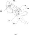
- the present disclosure provides a bidirectional driving mechanism for electric scissors blades, including a fixed seat 10, a driving gear 50, a rotating shaft member 40, an upper blade group 30 and a lower blade 20.
- the driving gear 50 and the rotating shaft member 40 are arranged on the fixed seat 10, the lower blade 20 and the upper blade group 30 rotate around the rotating shaft member 40, an outer rack 21 is arranged at a rear part of the lower blade 20, a front part of the upper blade group 30 is an upper blade 32, a rear part of the upper blade group 30 is a meshing block 33, and an inner rack 31 is arranged at a rear part of the meshing block 33; and the inner rack 31 and the outer rack 21 are respectively meshed with both sides of the driving gear 50.
- the driving gear 50 and the rotating shaft member 40 are arranged on the fixed seat 10, and the rotating shaft member 40 makes the upper blade group 30 and the lower blade 20 rotate around it.
- the meshing block 33 is arranged, the inner rack 31 is arranged at the rear part of the meshing block 33, the inner rack 31 faces the outer rack 21 at the rear part of the lower blade 20, and both sides of the driving gear 50 are meshed with the inner rack and the outer rack 21 respectively.
- the inner rack 31 and the driving gear 50 are located behind the outer rack 21, and there is no need to provide a position for mounting the driving gear between the upper blade 32 and the lower blade 20, such that the thickness is reduced.
- the driving gear 50, the upper blade 32 and the lower blade 20 all rotate in a circumferential direction in the same plane, and the situation that the upper blade 32 and the lower blade 20 open outwards since the circumferential rotation of the gear and the circumferential rotation of the upper blade 32 and the lower blade 20 are perpendicular to each other is avoided, thereby improving the stability of the bidirectional driving mechanism of electric scissors blades, and making the bidirectional driving mechanism of electric scissors blades more durable.
- the rotating shaft member 40 includes a stop screw 41 and a nut 42, a rotating shaft hole D is provided in the fixed seat 10, and the stop screw 41 passes through the rotating shaft hole D and is in threaded connection with the nut 42.
- the stop screw 41 includes a connecting rod (not shown) and a limiting cap (not shown), one end of the connecting rod is engaged with the limiting cap, and the other end of the connecting rod is provided with threads.
- the stop screw 41 and the nut 42 are arranged, and the stop screw 41 includes the connecting rod and the limiting cap, such that the detachable property is realized.
- a rotating shaft hole A is provided in a front part of the meshing block 33, a rotating shaft hole B is provided in a rear part of the upper blade 32, a rotating shaft hole C is provided in a middle part of the lower blade 20, and the rotating shaft hole A, the rotating shaft hole B and the rotating shaft hole C all rotate around the rotating shaft member 40;
- a pin hole E is also provided in the front part of the meshing block 33, a pin hole F is provided in the rear part of the upper blade 32, and a pin 34 is connected in both the pin hole E and the pin hole F.
- the meshing block 33 and the upper blade 32 are of detachable structures, and thus can be detached for separate replacement when the inner rack 31 on a meshing portion is used for a long time or the upper blade 32 is used for a long time and the accuracy decreases, which improves the flexibility of replacement.
- the pin 34 is arranged to cooperate with the rotating shaft member 40 to realize the mutual positioning and cooperation of the meshing block 33 and the upper blade 32, such that the meshing block 33 can drive the upper blade 32 to rotate to realize shearing.
- a first protrusion 331 is arranged at the front part of the meshing block 33, and the pin hole E is located at the first protrusion 331;
- a second protrusion 321 is arranged at the rear part of the upper blade 32, and the pin hole F is located at the second protrusion 321; and suitable positions are provided for the pin holes.
- the first protrusion 331 is arranged at a front upper side of the shaft hole A
- the second protrusion 321 is arranged at a front upper side of the shaft hole B.
- the outer rack 21 and the inner rack 31 are of arc-shaped structures; and the centers of circles corresponding to arcs of the outer rack 21 and the inner rack 31 are made correspond to a center line of the rotating shaft member 40, so as to realize close meshing with the driving gear 50.
- a gear hole 11 is provided in the fixed seat 10
- a deep groove bearing 12 is connected in the gear hole 11
- a pin shaft of the driving gear 50 is in running fit with the deep groove bearing 12, so as to realize rotation of the driving gear 50.
- An electric scissors includes a driving assembly.
- An output end of the driving assembly is dynamically connected to the pin shaft of the driving gear 50 to drive the driving gear 50 to rotate, and the rotation of the driving gear 50 drives the outer rack 21 and the inner rack 31 to rotate synchronously, such that the upper blade 32 and the lower blade 20 swing up and down to complete shearing.
- a bidirectional driving mechanism for electric scissors blades includes a fixed seat 10, a driving gear 50, a rotating shaft member 40, an upper blade group 30 and a lower blade 20.
- the driving gear 50 and the rotating shaft member 40 are arranged on the fixed seat 10, the lower blade 20 and the upper blade group 30 rotate around the rotating shaft member 40, an outer rack 21 is arranged at a rear part of the lower blade 20, a front part of the upper blade group 30 is the upper blade 32, a rear part of the upper blade group 30 is a meshing block 33, and an inner rack 31 is arranged at a rear part of the meshing block 33; and the inner rack 31 and the outer rack 21 are respectively meshed with both sides of the driving gear 50.
- the rotating shaft member 40 includes a stop screw 41 and a nut 42, a rotating shaft hole D is provided in the fixed seat 10, and the stop screw 41 passes through the rotating shaft hole D and is in threaded connection with the nut 42.
- the stop screw 41 includes a connecting rod and a limiting cap, one end of the connecting rod is engaged with the limiting cap, and the other end of the connecting rod is provided with threads.
- the driving assembly drives the driving gear 50 to rotate, under the rotation of the driving gear 50, the bidirectional driving mechanism for electric scissors blade drives the inner rack 31 and the outer rack 21 to swing, thereby driving the upper blade 32 and the lower blade 20 to shear.
- the nut 42 is loosened, the mechanism is entirely disassembled to replace the damaged part.
- a bidirectional driving mechanism for electric scissors blades includes a fixed seat 10, a driving gear 50, a rotating shaft member 40, an upper blade group 30 and a lower blade 20.
- the driving gear 50 and the rotating shaft member 40 are arranged on the fixed seat 10, the lower blade 20 and the upper blade group 30 rotate around the rotating shaft member 40, an outer rack 21 is arranged at a rear part of the lower blade 20, a front part of the upper blade group 30 is an upper blade 32, a rear part of the upper blade group 30 is a meshing block 33, and an inner rack 31 is arranged at a rear part of the meshing block 33.
- the inner rack 31 and the outer rack 21 are respectively meshed with both sides of the driving gear 50.
- the rotating shaft member 40 includes a stop screw 41 and a nut 42, a rotating shaft hole D is provided in the fixed seat 10, and the stop screw 41 passes through the rotating shaft hole D and is in threaded connection with the nut 42.
- the stop screw 41 includes a connecting rod and a limiting cap, one end of the connecting rod is engaged with the limiting cap, and the other end of the connecting rod is provided with threads.
- a rotating shaft hole A is provided in a front part of the meshing block 33
- a rotating shaft hole B is provided in a rear part of the upper blade 32
- a rotating shaft hole C is provided in a middle part of the lower blade 20, and the rotating shaft hole A, the rotating shaft hole B and the rotating shaft hole C all rotate around the rotating shaft member 40.
- a pin hole E is also provided in the front part of the meshing block 33, a pin hole F is provided in the rear part of the upper blade 32, and a pin 34 is connected in both the pin hole E and the pin hole F.
- the driving assembly drives the driving gear 50 to rotate, under the rotation of the driving gear 50, the bidirectional driving mechanism for electric scissors blade drives the inner rack 31 and the outer rack 21 to swing, thereby driving the upper blade 32 and the lower blade 20 to shear.
- the nut 42 is loosened, the mechanism is entirely disassembled to replace the damaged part. If the meshing block 33 or the upper blade 32 is damaged, the pin 34 is knocked out with a nail or similar tool, and then the meshing block 33 or the upper blade 32 is replaced.
Landscapes
- Life Sciences & Earth Sciences (AREA)
- Forests & Forestry (AREA)
- Biodiversity & Conservation Biology (AREA)
- Ecology (AREA)
- Environmental Sciences (AREA)
- Engineering & Computer Science (AREA)
- Mechanical Engineering (AREA)
- Scissors And Nippers (AREA)
Claims (8)
- - Bidirektionaler Antriebsmechanismus für Klingen einer elektrischen Schere, einen festen Sitz (10), ein Antriebsrad (50), ein Drehwellenelement (40), eine obere Klingengruppe (30) und eine untere Klinge (20) umfassend, wobei das Antriebsrad (50) und das Drehwellenelement (40) an dem festen Sitz (10) angeordnet sind, sich die untere Klinge (20) und die obere Klingengruppe (30) um das Drehwellenelement (40) drehen, an einem hinteren Teil der unteren Klinge (20) eine äußere Zahnstange (21) angeordnet ist, ein vorderer Teil der oberen Klingengruppe (30) eine obere Klinge (32) ist, ein hinterer Teil der oberen Klingengruppe (30) ein Eingriffsblock (33) ist und eine innere Zahnstange (31) an einem hinteren Teil des Eingriffsblocks (33) angeordnet ist und die innere Zahnstange (31) und die äußere Zahnstange (21) entsprechend mit beiden Seiten des Antriebsrades (50) in Eingriff stehen, in dem vorderen Teil des Eingriffsblocks (33) eine Stiftöffnung E bereitgestellt ist, in dem hinteren Teil der oberen Klinge (32) eine Stiftöffnung F bereitgestellt ist und ein Stift (34) in sowohl der Stiftöffnung E als auch der Stiftöffnung F verbunden ist,
wobei der bidirektionale Antriebsmechanismus dadurch gekennzeichnet ist, dass an dem vorderen Teil des Eingriffsblocks (33) ein erster Vorsprung angeordnet ist und sich die Stiftöffnung E an dem ersten Vorsprung befindet, und an dem hinteren Teil der oberen Klinge (32) ein zweiter Vorsprung angeordnet ist und sich die Stiftöffnung F an dem zweiten Vorsprung befindet. - - Bidirektionaler Antriebsmechanismus für Klingen einer elektrischen Schere nach Anspruch 1, wobei das Drehwellenelement (40) eine Anschlagschraube (41) und eine Mutter (42) umfasst, in dem festen Sitz eine Drehwellenöffnung D bereitgestellt ist und die Anschlagschraube (41) durch die Drehwellenöffnung D verläuft und in Gewindeverbindung mit der Mutter (42) steht.
- - Bidirektionaler Antriebsmechanismus für Klingen einer elektrischen Schere nach Anspruch 2, wobei die Anschlagschraube (41) eine Verbindungsstange und eine Begrenzungskappe umfasst, ein Ende der Verbindungsstange in Eingriff mit der Begrenzungskappe steht und das andere Ende der Verbindungsstange mit Gewinde versehen ist.
- - Bidirektionaler Antriebsmechanismus für Klingen einer elektrischen Schere nach Anspruch 3, wobei in einem vorderen Abschnitt des Eingriffsblocks (33) eine Drehwellenöffnung A bereitgestellt ist, in einem hinteren Teil der oberen Klinge (32) eine Drehwellenöffnung B bereitgestellt ist, in einem Mittelteil der unteren Klinge (21) eine Drehwellenöffnung C bereitgestellt ist und sich die Drehwellenöffnung A, die Drehwellenöffnung B und die Drehwellenöffnung C gemeinsam um das Drehwellenelement (40) drehen.
- - Bidirektionaler Antriebsmechanismus für Klingen einer elektrischen Schere nach Anspruch 1, wobei der erste Vorspruch an einer vorderen Oberseite der Wellenöffnung A angeordnet ist und der zweite Vorsprung an einer vorderen Oberseite der Wellenöffnung B angeordnet ist.
- - Bidirektionaler Antriebsmechanismus für Klingen einer elektrischen Schere nach Anspruch 1, wobei die äußere Zahnstange (21) und die innere Zahnstange (31) bogenförmige Strukturen sind.
- - Bidirektionaler Antriebsmechanismus für Klingen einer elektrischen Schere nach Anspruch 1, wobei in dem festen Sitz (10) eine Zahnradöffnung bereitgestellt ist, in der Zahnradöffnung (11) ein Rillenkugellager (12) verbunden ist und eine Stiftwelle des Antriebsrades (50) in Spielpassung mit dem Rillenkugellager (12) steht.
- - Elektrische Schere, den bidirektionalen Antriebsmechanismus für Klingen einer elektrischen Schere nach einem der Ansprüche 1 bis 7 umfassend, umfassend eine Antriebsanordnung, wobei ein Ausgabeende der Antriebsanordnung dynamisch mit der Stiftwelle des Antriebsrades (50) verbunden ist, um das Antriebsrad (50) zur Drehung anzutreiben.
Applications Claiming Priority (1)
| Application Number | Priority Date | Filing Date | Title |
|---|---|---|---|
| CN202011553727.4A CN112514673A (zh) | 2020-12-24 | 2020-12-24 | 电剪刀刀片双向驱动机构及电动剪刀 |
Publications (3)
| Publication Number | Publication Date |
|---|---|
| EP4019214A1 EP4019214A1 (de) | 2022-06-29 |
| EP4019214B1 true EP4019214B1 (de) | 2025-04-16 |
| EP4019214C0 EP4019214C0 (de) | 2025-04-16 |
Family
ID=74976327
Family Applications (1)
| Application Number | Title | Priority Date | Filing Date |
|---|---|---|---|
| EP21185380.9A Active EP4019214B1 (de) | 2020-12-24 | 2021-07-13 | Bidirektionaler antriebsmechanismus für elektrische scherenblätter sowie elektrische scherenblätter |
Country Status (9)
| Country | Link |
|---|---|
| US (1) | US11565433B2 (de) |
| EP (1) | EP4019214B1 (de) |
| JP (1) | JP7455091B2 (de) |
| KR (1) | KR102595738B1 (de) |
| CN (1) | CN112514673A (de) |
| AU (1) | AU2021204778B2 (de) |
| BR (1) | BR102021015175A2 (de) |
| CL (1) | CL2021002060A1 (de) |
| TW (1) | TWI781690B (de) |
Families Citing this family (11)
| Publication number | Priority date | Publication date | Assignee | Title |
|---|---|---|---|---|
| KR102927178B1 (ko) * | 2019-05-10 | 2026-02-13 | 로덴베르게르 아게 | 라쳇 기구를 가진 수동식 절단 장치 |
| JP6830558B1 (ja) * | 2020-04-21 | 2021-02-17 | アルスコーポレーション株式会社 | 電動剪定鋏 |
| US11833600B2 (en) * | 2021-05-26 | 2023-12-05 | Andrew Watzenboeck | Stick cutter |
| CN113661832A (zh) * | 2021-09-07 | 2021-11-19 | 石国欢 | 一种免人工采摘自助采集油茶籽的装置及使用方法 |
| CN118434523A (zh) | 2021-10-22 | 2024-08-02 | 环救援有限公司 | 用于安全地横切被困在附肢上的环状物的环状物切割器 |
| CN114365633A (zh) * | 2022-01-07 | 2022-04-19 | 金应太 | 一种双动电动剪刀 |
| EP4252523A1 (de) * | 2022-03-28 | 2023-10-04 | Zanon S.R.L. | Elektrische schere und verfahren zur verwendung solch einer schere |
| USD1089340S1 (en) | 2023-06-22 | 2025-08-19 | Ring Rescue Inc. | Ring cutter |
| JP1764746S (ja) * | 2023-06-27 | 2024-03-04 | 電動剪定鋏 | |
| CN117084064A (zh) * | 2023-08-31 | 2023-11-21 | 浙江工业大学 | 一种适用于多种类青椒的采摘末端执行器 |
| CN118575664B (zh) * | 2024-08-06 | 2024-10-18 | 泰州市泰禾晟园林绿化工程有限公司 | 一种园林树木修剪用的电剪刀 |
Family Cites Families (42)
| Publication number | Priority date | Publication date | Assignee | Title |
|---|---|---|---|---|
| JPH01300978A (ja) * | 1988-05-31 | 1989-12-05 | Mitsubishi Electric Corp | 対向部材を開閉する機構 |
| JP3537649B2 (ja) * | 1997-10-30 | 2004-06-14 | 株式会社マキタ | 電動式せん定はさみ |
| ATE277508T1 (de) * | 2000-12-05 | 2004-10-15 | Hispaes S A | Tragbare schere mit motorantrieb |
| ES2178947B1 (es) * | 2000-12-05 | 2004-04-01 | Hispaes, Sa | Tijera portatil motorizada. |
| US20050115081A1 (en) | 2003-11-27 | 2005-06-02 | Shu-Woan Tu | Electric cutter |
| US6973727B2 (en) * | 2004-01-22 | 2005-12-13 | Ching Hsiu Yao | Electric driving scissors |
| EP1827772A1 (de) * | 2004-10-18 | 2007-09-05 | Koninklijke Philips Electronics N.V. | Scheren und antriebe für scheren |
| JP5034348B2 (ja) * | 2006-07-20 | 2012-09-26 | マックス株式会社 | 電動式ハサミ |
| US7971360B2 (en) * | 2008-05-02 | 2011-07-05 | Kett Tool Company | Powered hand-held metal cutter |
| IL193233A (en) | 2008-08-04 | 2012-12-31 | Iscar Ltd | Cutting tool having a bidirectional adjustment mechanism |
| FR2935106B1 (fr) * | 2008-08-22 | 2010-09-17 | Pellenc Sa | Outil electroportatif a commande par gachette |
| EP2158805B1 (de) * | 2008-08-26 | 2011-11-02 | Robert Bosch GmbH | Schneidwerkzeug für Pflanzen |
| CN101876812B (zh) * | 2009-04-28 | 2012-07-04 | 南京德朔实业有限公司 | 电剪刀的控制方法 |
| CN102715023B (zh) * | 2011-03-31 | 2014-07-30 | 南京德朔实业有限公司 | 电动修枝剪 |
| JP5741252B2 (ja) | 2011-06-28 | 2015-07-01 | マックス株式会社 | 電動はさみ |
| CN102310222B (zh) * | 2011-09-06 | 2013-08-21 | 南京德朔实业有限公司 | 可安全换刀片的电动工具 |
| ITMI20112279A1 (it) * | 2011-12-15 | 2013-06-16 | Davide E Luigi Volpi S P A | Forbice motorizzata da potatura |
| CN103181300A (zh) * | 2011-12-27 | 2013-07-03 | 皇田工业股份有限公司 | 可控制剪口的高枝剪 |
| EP2682238B1 (de) * | 2012-07-06 | 2015-05-27 | FELCO Motion SA | Mobiles Elektroinstrument |
| US9796099B2 (en) * | 2014-04-08 | 2017-10-24 | Terry Sandefur | Cutting apparatus |
| US10449680B2 (en) * | 2014-04-08 | 2019-10-22 | Terry Sandefur | Cutting apparatus |
| CN204149213U (zh) * | 2014-08-26 | 2015-02-11 | 宁波爱特工具有限公司 | 裁管刀 |
| FR3028716B1 (fr) * | 2014-11-25 | 2016-11-25 | Pellenc Sa | Outil electroportatif, et en particulier secateur electrique a dissipateur thermique. |
| US20160150738A1 (en) * | 2014-12-02 | 2016-06-02 | Brian Hall | Cutting assembly |
| US20160219793A1 (en) * | 2015-02-03 | 2016-08-04 | Ma Xianpeng | High-torsion electric pruning shears |
| CN104604545B (zh) * | 2015-02-12 | 2017-06-06 | 东莞市嘉航实业有限公司 | 电动修枝剪刀 |
| JP6467314B2 (ja) * | 2015-08-04 | 2019-02-13 | 株式会社マキタ | 電動はさみ |
| US10172292B2 (en) * | 2016-10-17 | 2019-01-08 | Robert Bosch Gmbh | Cutting device |
| US9757869B1 (en) * | 2016-12-22 | 2017-09-12 | Yoshikazu Wada | Electric scissors |
| CN107409781A (zh) * | 2017-05-25 | 2017-12-01 | 东莞市嘉航实业有限公司 | 一种电动剪刀 |
| CN207720708U (zh) * | 2018-01-10 | 2018-08-14 | 张萤 | 一种适用于城市园林的电动剪草装置 |
| CN108040580A (zh) * | 2018-01-10 | 2018-05-18 | 张萤 | 一种适用于城市园林的电动剪草装置 |
| TWM572297U (zh) * | 2018-09-17 | 2019-01-01 | 鼎隆工業股份有限公司 | Pneumatic scissors tool |
| DE102018251740A1 (de) * | 2018-12-27 | 2020-07-02 | Robert Bosch Gmbh | Schneidvorrichtung |
| CN209539931U (zh) * | 2019-03-08 | 2019-10-25 | 南阳利博精密传动有限公司 | 一种新型园林电动剪刀的齿轮传动装置 |
| CN211832012U (zh) * | 2020-03-30 | 2020-11-03 | 永康市为得工贸有限公司 | 刀片机构及具有该刀片机构的电动剪刀 |
| CN111480469A (zh) * | 2020-05-13 | 2020-08-04 | 曲伟 | 一种园林剪 |
| CN111512813B (zh) * | 2020-05-13 | 2024-11-22 | 东莞市尚峰精密机械有限公司 | 一种双动刀片电动剪刀 |
| CN111527903A (zh) * | 2020-05-17 | 2020-08-14 | 东莞市嘉航实业有限公司 | 一种双刀传动机构以及带有该双刀传动机构的电动剪刀 |
| CN112106542A (zh) * | 2020-07-30 | 2020-12-22 | 江苏东成工具科技有限公司 | 电动修枝剪 |
| CN111903365B (zh) * | 2020-09-24 | 2025-01-24 | 辛皓天 | 反置式双刀联动电动树枝剪 |
| CN214430364U (zh) * | 2020-12-24 | 2021-10-22 | 东莞市嘉航实业有限公司 | 电剪刀刀片双向驱动机构及电动剪刀 |
-
2020
- 2020-12-24 CN CN202011553727.4A patent/CN112514673A/zh active Pending
-
2021
- 2021-07-07 US US17/368,862 patent/US11565433B2/en active Active
- 2021-07-08 AU AU2021204778A patent/AU2021204778B2/en active Active
- 2021-07-13 EP EP21185380.9A patent/EP4019214B1/de active Active
- 2021-07-16 JP JP2021117612A patent/JP7455091B2/ja active Active
- 2021-07-16 TW TW110126202A patent/TWI781690B/zh active
- 2021-07-30 BR BR102021015175-7A patent/BR102021015175A2/pt unknown
- 2021-08-04 CL CL2021002060A patent/CL2021002060A1/es unknown
- 2021-08-18 KR KR1020210108716A patent/KR102595738B1/ko active Active
Also Published As
| Publication number | Publication date |
|---|---|
| KR102595738B1 (ko) | 2023-10-27 |
| TW202224553A (zh) | 2022-07-01 |
| US20210331337A1 (en) | 2021-10-28 |
| EP4019214A1 (de) | 2022-06-29 |
| AU2021204778A1 (en) | 2022-07-14 |
| AU2021204778B2 (en) | 2023-06-15 |
| KR20220092347A (ko) | 2022-07-01 |
| JP2022101437A (ja) | 2022-07-06 |
| EP4019214C0 (de) | 2025-04-16 |
| TWI781690B (zh) | 2022-10-21 |
| US11565433B2 (en) | 2023-01-31 |
| JP7455091B2 (ja) | 2024-03-25 |
| CL2021002060A1 (es) | 2022-06-10 |
| BR102021015175A2 (pt) | 2022-07-05 |
| CN112514673A (zh) | 2021-03-19 |
Similar Documents
| Publication | Publication Date | Title |
|---|---|---|
| EP4019214B1 (de) | Bidirektionaler antriebsmechanismus für elektrische scherenblätter sowie elektrische scherenblätter | |
| CA2714773C (en) | Electric shears | |
| EP2604106B1 (de) | Motorbetriebene Astschere | |
| EP4268572A1 (de) | Baumscherenkopf-aufsatz | |
| CN214430364U (zh) | 电剪刀刀片双向驱动机构及电动剪刀 | |
| JP2017192347A (ja) | 電動刈り込み鋏 | |
| CN214430367U (zh) | 一种新型电剪刀双刀驱动机构及电动剪刀 | |
| CN112514675B (zh) | 一种电剪刀双刀驱动机构及电动剪刀 | |
| GB2591388A (en) | Cutting assembly | |
| CN110558083A (zh) | 一种观景树修剪装置 | |
| CN115443810A (zh) | 一种自动剪枝采果器 | |
| CN212324810U (zh) | 一种新型双动刀片电动剪刀 | |
| CN2860049Y (zh) | 一种电动修枝剪 | |
| CN112514674B (zh) | 一种电剪刀双连杆双刀驱动机构及其电动剪刀 | |
| JP4469224B2 (ja) | ヘッジトリマー | |
| CN220712173U (zh) | 一种林业工程用树木修剪机 | |
| CN216820805U (zh) | 一种电动剪刀 | |
| CN217608484U (zh) | 一种用于绿化带修剪的装配式变形臂 | |
| CN220428499U (zh) | 一种造纸机分切装置 | |
| CN215421797U (zh) | 一种树枝修剪装置 | |
| CN102528150B (zh) | 切割附件及使用该附件的摆动动力工具 | |
| CN114365633A (zh) | 一种双动电动剪刀 | |
| CN208562424U (zh) | 真皮裁剪机的裁刀机构 | |
| CN120814422A (zh) | 一种电动修枝剪 | |
| CN207678382U (zh) | 一种户外供电线路砍青工具 |
Legal Events
| Date | Code | Title | Description |
|---|---|---|---|
| PUAI | Public reference made under article 153(3) epc to a published international application that has entered the european phase |
Free format text: ORIGINAL CODE: 0009012 |
|
| STAA | Information on the status of an ep patent application or granted ep patent |
Free format text: STATUS: REQUEST FOR EXAMINATION WAS MADE |
|
| 17P | Request for examination filed |
Effective date: 20210812 |
|
| AK | Designated contracting states |
Kind code of ref document: A1 Designated state(s): AL AT BE BG CH CY CZ DE DK EE ES FI FR GB GR HR HU IE IS IT LI LT LU LV MC MK MT NL NO PL PT RO RS SE SI SK SM TR |
|
| RBV | Designated contracting states (corrected) |
Designated state(s): AL AT BE BG CH CY CZ DE DK EE ES FI FR GB GR HR HU IE IS IT LI LT LU LV MC MK MT NL NO PL PT RO RS SE SI SK SM TR |
|
| GRAP | Despatch of communication of intention to grant a patent |
Free format text: ORIGINAL CODE: EPIDOSNIGR1 |
|
| STAA | Information on the status of an ep patent application or granted ep patent |
Free format text: STATUS: GRANT OF PATENT IS INTENDED |
|
| INTG | Intention to grant announced |
Effective date: 20241107 |
|
| GRAS | Grant fee paid |
Free format text: ORIGINAL CODE: EPIDOSNIGR3 |
|
| GRAA | (expected) grant |
Free format text: ORIGINAL CODE: 0009210 |
|
| STAA | Information on the status of an ep patent application or granted ep patent |
Free format text: STATUS: THE PATENT HAS BEEN GRANTED |
|
| AK | Designated contracting states |
Kind code of ref document: B1 Designated state(s): AL AT BE BG CH CY CZ DE DK EE ES FI FR GB GR HR HU IE IS IT LI LT LU LV MC MK MT NL NO PL PT RO RS SE SI SK SM TR |
|
| REG | Reference to a national code |
Ref country code: GB Ref legal event code: FG4D |
|
| REG | Reference to a national code |
Ref country code: CH Ref legal event code: EP |
|
| REG | Reference to a national code |
Ref country code: IE Ref legal event code: FG4D |
|
| REG | Reference to a national code |
Ref country code: DE Ref legal event code: R096 Ref document number: 602021029143 Country of ref document: DE |
|
| U01 | Request for unitary effect filed |
Effective date: 20250423 |
|
| U07 | Unitary effect registered |
Designated state(s): AT BE BG DE DK EE FI FR IT LT LU LV MT NL PT RO SE SI Effective date: 20250502 |
|
| U20 | Renewal fee for the european patent with unitary effect paid |
Year of fee payment: 5 Effective date: 20250604 |
|
| PG25 | Lapsed in a contracting state [announced via postgrant information from national office to epo] |
Ref country code: ES Free format text: LAPSE BECAUSE OF FAILURE TO SUBMIT A TRANSLATION OF THE DESCRIPTION OR TO PAY THE FEE WITHIN THE PRESCRIBED TIME-LIMIT Effective date: 20250416 |
|
| PG25 | Lapsed in a contracting state [announced via postgrant information from national office to epo] |
Ref country code: GR Free format text: LAPSE BECAUSE OF FAILURE TO SUBMIT A TRANSLATION OF THE DESCRIPTION OR TO PAY THE FEE WITHIN THE PRESCRIBED TIME-LIMIT Effective date: 20250717 Ref country code: NO Free format text: LAPSE BECAUSE OF FAILURE TO SUBMIT A TRANSLATION OF THE DESCRIPTION OR TO PAY THE FEE WITHIN THE PRESCRIBED TIME-LIMIT Effective date: 20250716 |
|
| PG25 | Lapsed in a contracting state [announced via postgrant information from national office to epo] |
Ref country code: PL Free format text: LAPSE BECAUSE OF FAILURE TO SUBMIT A TRANSLATION OF THE DESCRIPTION OR TO PAY THE FEE WITHIN THE PRESCRIBED TIME-LIMIT Effective date: 20250416 |
|
| PG25 | Lapsed in a contracting state [announced via postgrant information from national office to epo] |
Ref country code: HR Free format text: LAPSE BECAUSE OF FAILURE TO SUBMIT A TRANSLATION OF THE DESCRIPTION OR TO PAY THE FEE WITHIN THE PRESCRIBED TIME-LIMIT Effective date: 20250416 |
|
| PG25 | Lapsed in a contracting state [announced via postgrant information from national office to epo] |
Ref country code: RS Free format text: LAPSE BECAUSE OF FAILURE TO SUBMIT A TRANSLATION OF THE DESCRIPTION OR TO PAY THE FEE WITHIN THE PRESCRIBED TIME-LIMIT Effective date: 20250716 |
|
| PG25 | Lapsed in a contracting state [announced via postgrant information from national office to epo] |
Ref country code: IS Free format text: LAPSE BECAUSE OF FAILURE TO SUBMIT A TRANSLATION OF THE DESCRIPTION OR TO PAY THE FEE WITHIN THE PRESCRIBED TIME-LIMIT Effective date: 20250816 |
|
| PG25 | Lapsed in a contracting state [announced via postgrant information from national office to epo] |
Ref country code: SM Free format text: LAPSE BECAUSE OF FAILURE TO SUBMIT A TRANSLATION OF THE DESCRIPTION OR TO PAY THE FEE WITHIN THE PRESCRIBED TIME-LIMIT Effective date: 20250416 |
|
| PG25 | Lapsed in a contracting state [announced via postgrant information from national office to epo] |
Ref country code: CZ Free format text: LAPSE BECAUSE OF FAILURE TO SUBMIT A TRANSLATION OF THE DESCRIPTION OR TO PAY THE FEE WITHIN THE PRESCRIBED TIME-LIMIT Effective date: 20250416 |
|
| PG25 | Lapsed in a contracting state [announced via postgrant information from national office to epo] |
Ref country code: SK Free format text: LAPSE BECAUSE OF FAILURE TO SUBMIT A TRANSLATION OF THE DESCRIPTION OR TO PAY THE FEE WITHIN THE PRESCRIBED TIME-LIMIT Effective date: 20250416 |
|
| PLBE | No opposition filed within time limit |
Free format text: ORIGINAL CODE: 0009261 |
|
| STAA | Information on the status of an ep patent application or granted ep patent |
Free format text: STATUS: NO OPPOSITION FILED WITHIN TIME LIMIT |
|
| REG | Reference to a national code |
Ref country code: CH Ref legal event code: H13 Free format text: ST27 STATUS EVENT CODE: U-0-0-H10-H13 (AS PROVIDED BY THE NATIONAL OFFICE) Effective date: 20260224 |
|
| REG | Reference to a national code |
Ref country code: CH Ref legal event code: L10 Free format text: ST27 STATUS EVENT CODE: U-0-0-L10-L00 (AS PROVIDED BY THE NATIONAL OFFICE) Effective date: 20260225 |
|
| 26N | No opposition filed |
Effective date: 20260119 |
|
| GBPC | Gb: european patent ceased through non-payment of renewal fee |
Effective date: 20250716 |
|
| PG25 | Lapsed in a contracting state [announced via postgrant information from national office to epo] |
Ref country code: GB Free format text: LAPSE BECAUSE OF NON-PAYMENT OF DUE FEES Effective date: 20250716 |
|
| PG25 | Lapsed in a contracting state [announced via postgrant information from national office to epo] |
Ref country code: CH Free format text: LAPSE BECAUSE OF NON-PAYMENT OF DUE FEES Effective date: 20250731 |