EP4019220A1 - Moule, procédé de fabrication de structure préformée assemblée et procédé de fabrication de structure de panneau mural - Google Patents
Moule, procédé de fabrication de structure préformée assemblée et procédé de fabrication de structure de panneau mural Download PDFInfo
- Publication number
- EP4019220A1 EP4019220A1 EP20855278.6A EP20855278A EP4019220A1 EP 4019220 A1 EP4019220 A1 EP 4019220A1 EP 20855278 A EP20855278 A EP 20855278A EP 4019220 A1 EP4019220 A1 EP 4019220A1
- Authority
- EP
- European Patent Office
- Prior art keywords
- mold
- shaped
- stringer
- layer
- base
- Prior art date
- Legal status (The legal status is an assumption and is not a legal conclusion. Google has not performed a legal analysis and makes no representation as to the accuracy of the status listed.)
- Granted
Links
Images


Classifications
-
- B—PERFORMING OPERATIONS; TRANSPORTING
- B29—WORKING OF PLASTICS; WORKING OF SUBSTANCES IN A PLASTIC STATE IN GENERAL
- B29D—PRODUCING PARTICULAR ARTICLES FROM PLASTICS OR FROM SUBSTANCES IN A PLASTIC STATE
- B29D99/00—Subject matter not provided for in other groups of this subclass
- B29D99/0003—Producing profiled members, e.g. beams
-
- B—PERFORMING OPERATIONS; TRANSPORTING
- B29—WORKING OF PLASTICS; WORKING OF SUBSTANCES IN A PLASTIC STATE IN GENERAL
- B29B—PREPARATION OR PRETREATMENT OF THE MATERIAL TO BE SHAPED; MAKING GRANULES OR PREFORMS; RECOVERY OF PLASTICS OR OTHER CONSTITUENTS OF WASTE MATERIAL CONTAINING PLASTICS
- B29B11/00—Making preforms
- B29B11/06—Making preforms by moulding the material
-
- B—PERFORMING OPERATIONS; TRANSPORTING
- B29—WORKING OF PLASTICS; WORKING OF SUBSTANCES IN A PLASTIC STATE IN GENERAL
- B29C—SHAPING OR JOINING OF PLASTICS; SHAPING OF MATERIAL IN A PLASTIC STATE, NOT OTHERWISE PROVIDED FOR; AFTER-TREATMENT OF THE SHAPED PRODUCTS, e.g. REPAIRING
- B29C33/00—Moulds or cores; Details thereof or accessories therefor
- B29C33/30—Mounting, exchanging or centering
- B29C33/301—Modular mould systems [MMS], i.e. moulds built up by stacking mould elements, e.g. plates, blocks, rods
-
- B—PERFORMING OPERATIONS; TRANSPORTING
- B29—WORKING OF PLASTICS; WORKING OF SUBSTANCES IN A PLASTIC STATE IN GENERAL
- B29C—SHAPING OR JOINING OF PLASTICS; SHAPING OF MATERIAL IN A PLASTIC STATE, NOT OTHERWISE PROVIDED FOR; AFTER-TREATMENT OF THE SHAPED PRODUCTS, e.g. REPAIRING
- B29C33/00—Moulds or cores; Details thereof or accessories therefor
- B29C33/30—Mounting, exchanging or centering
- B29C33/305—Mounting of moulds or mould support plates
-
- B—PERFORMING OPERATIONS; TRANSPORTING
- B29—WORKING OF PLASTICS; WORKING OF SUBSTANCES IN A PLASTIC STATE IN GENERAL
- B29C—SHAPING OR JOINING OF PLASTICS; SHAPING OF MATERIAL IN A PLASTIC STATE, NOT OTHERWISE PROVIDED FOR; AFTER-TREATMENT OF THE SHAPED PRODUCTS, e.g. REPAIRING
- B29C65/00—Joining or sealing of preformed parts, e.g. welding of plastics materials; Apparatus therefor
- B29C65/70—Joining or sealing of preformed parts, e.g. welding of plastics materials; Apparatus therefor by moulding
-
- B—PERFORMING OPERATIONS; TRANSPORTING
- B29—WORKING OF PLASTICS; WORKING OF SUBSTANCES IN A PLASTIC STATE IN GENERAL
- B29C—SHAPING OR JOINING OF PLASTICS; SHAPING OF MATERIAL IN A PLASTIC STATE, NOT OTHERWISE PROVIDED FOR; AFTER-TREATMENT OF THE SHAPED PRODUCTS, e.g. REPAIRING
- B29C66/00—General aspects of processes or apparatus for joining preformed parts
- B29C66/001—Joining in special atmospheres
- B29C66/0012—Joining in special atmospheres characterised by the type of environment
- B29C66/0014—Gaseous environments
- B29C66/00145—Vacuum, e.g. partial vacuum
-
- B—PERFORMING OPERATIONS; TRANSPORTING
- B29—WORKING OF PLASTICS; WORKING OF SUBSTANCES IN A PLASTIC STATE IN GENERAL
- B29C—SHAPING OR JOINING OF PLASTICS; SHAPING OF MATERIAL IN A PLASTIC STATE, NOT OTHERWISE PROVIDED FOR; AFTER-TREATMENT OF THE SHAPED PRODUCTS, e.g. REPAIRING
- B29C70/00—Shaping composites, i.e. plastics material comprising reinforcements, fillers or preformed parts, e.g. inserts
- B29C70/04—Shaping composites, i.e. plastics material comprising reinforcements, fillers or preformed parts, e.g. inserts comprising reinforcements only, e.g. self-reinforcing plastics
- B29C70/28—Shaping operations therefor
- B29C70/30—Shaping by lay-up, i.e. applying fibres, tape or broadsheet on a mould, former or core; Shaping by spray-up, i.e. spraying of fibres on a mould, former or core
- B29C70/34—Shaping by lay-up, i.e. applying fibres, tape or broadsheet on a mould, former or core; Shaping by spray-up, i.e. spraying of fibres on a mould, former or core and shaping or impregnating by compression, i.e. combined with compressing after the lay-up operation
- B29C70/342—Shaping by lay-up, i.e. applying fibres, tape or broadsheet on a mould, former or core; Shaping by spray-up, i.e. spraying of fibres on a mould, former or core and shaping or impregnating by compression, i.e. combined with compressing after the lay-up operation using isostatic pressure
-
- B—PERFORMING OPERATIONS; TRANSPORTING
- B29—WORKING OF PLASTICS; WORKING OF SUBSTANCES IN A PLASTIC STATE IN GENERAL
- B29C—SHAPING OR JOINING OF PLASTICS; SHAPING OF MATERIAL IN A PLASTIC STATE, NOT OTHERWISE PROVIDED FOR; AFTER-TREATMENT OF THE SHAPED PRODUCTS, e.g. REPAIRING
- B29C70/00—Shaping composites, i.e. plastics material comprising reinforcements, fillers or preformed parts, e.g. inserts
- B29C70/04—Shaping composites, i.e. plastics material comprising reinforcements, fillers or preformed parts, e.g. inserts comprising reinforcements only, e.g. self-reinforcing plastics
- B29C70/28—Shaping operations therefor
- B29C70/30—Shaping by lay-up, i.e. applying fibres, tape or broadsheet on a mould, former or core; Shaping by spray-up, i.e. spraying of fibres on a mould, former or core
- B29C70/34—Shaping by lay-up, i.e. applying fibres, tape or broadsheet on a mould, former or core; Shaping by spray-up, i.e. spraying of fibres on a mould, former or core and shaping or impregnating by compression, i.e. combined with compressing after the lay-up operation
- B29C70/345—Shaping by lay-up, i.e. applying fibres, tape or broadsheet on a mould, former or core; Shaping by spray-up, i.e. spraying of fibres on a mould, former or core and shaping or impregnating by compression, i.e. combined with compressing after the lay-up operation using matched moulds
-
- B—PERFORMING OPERATIONS; TRANSPORTING
- B29—WORKING OF PLASTICS; WORKING OF SUBSTANCES IN A PLASTIC STATE IN GENERAL
- B29C—SHAPING OR JOINING OF PLASTICS; SHAPING OF MATERIAL IN A PLASTIC STATE, NOT OTHERWISE PROVIDED FOR; AFTER-TREATMENT OF THE SHAPED PRODUCTS, e.g. REPAIRING
- B29C70/00—Shaping composites, i.e. plastics material comprising reinforcements, fillers or preformed parts, e.g. inserts
- B29C70/04—Shaping composites, i.e. plastics material comprising reinforcements, fillers or preformed parts, e.g. inserts comprising reinforcements only, e.g. self-reinforcing plastics
- B29C70/28—Shaping operations therefor
- B29C70/40—Shaping or impregnating by compression not applied
- B29C70/42—Shaping or impregnating by compression not applied for producing articles of definite length, i.e. discrete articles
- B29C70/44—Shaping or impregnating by compression not applied for producing articles of definite length, i.e. discrete articles using isostatic pressure, e.g. pressure difference-moulding, vacuum bag-moulding, autoclave-moulding or expanding rubber-moulding
- B29C70/446—Moulding structures having an axis of symmetry or at least one channel, e.g. tubular structures, frames
-
- B—PERFORMING OPERATIONS; TRANSPORTING
- B29—WORKING OF PLASTICS; WORKING OF SUBSTANCES IN A PLASTIC STATE IN GENERAL
- B29C—SHAPING OR JOINING OF PLASTICS; SHAPING OF MATERIAL IN A PLASTIC STATE, NOT OTHERWISE PROVIDED FOR; AFTER-TREATMENT OF THE SHAPED PRODUCTS, e.g. REPAIRING
- B29C70/00—Shaping composites, i.e. plastics material comprising reinforcements, fillers or preformed parts, e.g. inserts
- B29C70/68—Shaping composites, i.e. plastics material comprising reinforcements, fillers or preformed parts, e.g. inserts by incorporating or moulding on preformed parts, e.g. inserts or layers, e.g. foam blocks
- B29C70/74—Moulding material on a relatively small portion of the preformed part, e.g. outsert moulding
- B29C70/76—Moulding on edges or extremities of the preformed part
-
- B—PERFORMING OPERATIONS; TRANSPORTING
- B29—WORKING OF PLASTICS; WORKING OF SUBSTANCES IN A PLASTIC STATE IN GENERAL
- B29D—PRODUCING PARTICULAR ARTICLES FROM PLASTICS OR FROM SUBSTANCES IN A PLASTIC STATE
- B29D99/00—Subject matter not provided for in other groups of this subclass
- B29D99/001—Producing wall or panel-like structures, e.g. for hulls, fuselages, or buildings
- B29D99/0014—Producing wall or panel-like structures, e.g. for hulls, fuselages, or buildings provided with ridges or ribs, e.g. joined ribs
-
- B—PERFORMING OPERATIONS; TRANSPORTING
- B29—WORKING OF PLASTICS; WORKING OF SUBSTANCES IN A PLASTIC STATE IN GENERAL
- B29C—SHAPING OR JOINING OF PLASTICS; SHAPING OF MATERIAL IN A PLASTIC STATE, NOT OTHERWISE PROVIDED FOR; AFTER-TREATMENT OF THE SHAPED PRODUCTS, e.g. REPAIRING
- B29C33/00—Moulds or cores; Details thereof or accessories therefor
- B29C33/38—Moulds or cores; Details thereof or accessories therefor characterised by the material or the manufacturing process
- B29C33/3842—Manufacturing moulds, e.g. shaping the mould surface by machining
- B29C2033/385—Manufacturing moulds, e.g. shaping the mould surface by machining by laminating a plurality of layers
-
- B—PERFORMING OPERATIONS; TRANSPORTING
- B29—WORKING OF PLASTICS; WORKING OF SUBSTANCES IN A PLASTIC STATE IN GENERAL
- B29C—SHAPING OR JOINING OF PLASTICS; SHAPING OF MATERIAL IN A PLASTIC STATE, NOT OTHERWISE PROVIDED FOR; AFTER-TREATMENT OF THE SHAPED PRODUCTS, e.g. REPAIRING
- B29C2791/00—Shaping characteristics in general
- B29C2791/004—Shaping under special conditions
- B29C2791/006—Using vacuum
-
- B—PERFORMING OPERATIONS; TRANSPORTING
- B29—WORKING OF PLASTICS; WORKING OF SUBSTANCES IN A PLASTIC STATE IN GENERAL
- B29L—INDEXING SCHEME ASSOCIATED WITH SUBCLASS B29C, RELATING TO PARTICULAR ARTICLES
- B29L2031/00—Other particular articles
- B29L2031/30—Vehicles, e.g. ships or aircraft, or body parts thereof
- B29L2031/3076—Aircrafts
- B29L2031/3082—Fuselages
-
- Y—GENERAL TAGGING OF NEW TECHNOLOGICAL DEVELOPMENTS; GENERAL TAGGING OF CROSS-SECTIONAL TECHNOLOGIES SPANNING OVER SEVERAL SECTIONS OF THE IPC; TECHNICAL SUBJECTS COVERED BY FORMER USPC CROSS-REFERENCE ART COLLECTIONS [XRACs] AND DIGESTS
- Y02—TECHNOLOGIES OR APPLICATIONS FOR MITIGATION OR ADAPTATION AGAINST CLIMATE CHANGE
- Y02T—CLIMATE CHANGE MITIGATION TECHNOLOGIES RELATED TO TRANSPORTATION
- Y02T50/00—Aeronautics or air transport
- Y02T50/40—Weight reduction
Definitions
- the present application relates to the field of aerospace manufacturing and for example, relates to a mold, a manufacturing method of a fabricated preformed structure and a manufacturing method of a wall panel structure.
- Composite materials have been widely applied in the aerospace field because of their advantages such as high specific stiffness, ease of design and integral molding.
- main force-bearing components such as wing skins (also known as wing panels), fuselages, horizontal stabilizers, ailerons, vertical tails, sidewall panels, bulkheads, wing ribs and stiffeners.
- wall panels using T-shaped and U-shaped stringers as stiffeners have been widely used in the main force-bearing structure of the fuselage.
- the existing U-shaped stringer unit layup molds are mostly right-angle profile all-steel molds.
- the present application provides a mold for preforming of a U-shaped stringer.
- the mold reduces the manufacturing cost of the mold, indirectly improves the efficiency of laying a U-shaped prepreg layer on a skin layer, improves the corner quality of the stringer, ensures the product quality and precision, and simplifies the technological process.
- the present application provides a manufacturing method of a U-shaped stringer fabricated preformed structure.
- the manufacturing method improves the efficiency of laying a U-shaped prepreg layer on a skin layer, reduces the manufacturing cost of the mold, improves the corner quality of the stringer, ensures the product quality and precision, and simplifies the technological process.
- the present application provides a manufacturing method of a U-shaped stringer wall panel structure.
- the manufacturing method improves the efficiency of laying a U-shaped prepreg layer on a skin layer, reduces the manufacturing cost of the mold, improves the corner quality of the stringer, ensures the product quality and precision, and simplifies the technological process.
- One embodiment provides a mold for preforming of a U-shaped stringer.
- the mold includes a base, a rigid mold and an elastic mold.
- the rigid mold is detachably arranged on the base.
- the rigid mold is of a U-shaped structure, and is wrapped around the three adjacent external sidewall surfaces of the base.
- the elastic mold is arranged on the rigid mold.
- the elastic mold is of a U-shaped structure, and is wrapped on the external sidewall surface of the rigid mold.
- One embodiment provides a manufacturing method of a U-shaped stringer fabricated preformed structure.
- the method adopts the mold for preforming of the U-shaped stringer described above, and includes the following steps.
- the rigid mold is installed on the base.
- a multi-layer structure is laid on the rigid mold, and the multi-layer structure is cured and milled to form the elastic mold having a U-shaped structure.
- a prepreg layer is laid on the elastic mold, a U-shaped prepreg layer is formed by performing vacuum preloading on the prepreg layer, and a U-shaped stringer preformed structure is formed by the base, the rigid mold, the elastic mold and the U-shaped prepreg layer.
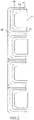
- U-shaped stringer preformed structures are distributed in a horizontal direction, and an intermediate interlayer is disposed between two adjacent U-shaped stringer preformed structures.
- One embodiment provides a manufacturing method of a U-shaped stringer wall panel structure.
- the method adopts the U-shaped stringer fabricated preformed structure manufactured by the method described above, and includes the following steps.
- the base is removed from the U-shaped stringer fabricated preformed structure.
- a skin tooling laid with a skin layer is placed in the horizontal direction.
- the U-shaped stringer fabricated preformed structure in which the base is removed is rotated 180 degrees and then placed on the skin layer.
- Vacuum packaging is performed on the U-shaped prepreg layer and the skin layer, and the U-shaped prepreg layer and the skin layer are co-cured or co-bound and molded at a given temperature and pressure.
- the skin tooling, multiple rigid molds and multiple elastic molds are removed.
- the mold for preforming of the U-shaped stringer in the present application includes a base 1, a rigid mold 2 and an elastic mold 3.
- the rigid mold 2 is detachably arranged on the base 1.
- the rigid mold 2 is of a U-shaped structure, and is wrapped on the three adjacent external sidewall surfaces of the base 1.
- the elastic mold 3 is arranged on the rigid mold 2.
- the elastic mold 3 is of a U-shaped structure, and is wrapped on the external sidewall surface of the rigid mold 2.
- the mold for preforming of the U-shaped stringer is an important basis for manufacturing the U-shaped stringer wall panel structure.
- the mold reduces the manufacturing cost of the mold, indirectly improves the efficiency of laying the U-shaped prepreg layer 4 on the skin layer 7, improves the corner quality of the stringer, ensures the product quality and precision, and simplifies the technological process.
- the rigid mold 2 is of a U-shaped structure, which ensures the positioning and longitudinal collimation of the stringer.
- the elastic mold 3 is of a U-shaped structure, and its thermal expansion ensures the effective transmission of the normal pressure on fiber layers at the corners and the triangular areas of the U-shaped stringer, avoiding defects such as fiber delamination and voids caused by failure of full pressure transmission and ensuring the quality of the U-shaped stringer wall panel structure.
- the elastic mold 3 adopts the structure form of AIRPAD rubber sheet + prepreg layer + AIRPAD rubber sheet.
- the elastic mold 3 can select other structure forms according to specific requirements.
- the base 1 includes a bottom portion 11 and a raised portion 12.
- the raised portion 12 is connected to the bottom portion 11.
- the rigid mold 2 is wrapped on the external sidewall surface of the raised portion 12 and two opposite external sidewall surfaces of the bottom portion 11.
- the raised portion 12 has a width gradually decreased in a direction away from the bottom portion11.
- the raised portion 12 has the width gradually decreased in the direction away from the bottom portion11, it can be known that the raised portion 12 has a ladder structure having a narrow top and a wide bottom, which facilitates the operator to remove the rigid mold 2 from the base 1.
- the bottom portion 11 and the raised portion 12 may be integrally formed, or can be fixedly connected by welding, bonding or other methods.
- one of the base 1 and the rigid mold 2 is provided with a clamping slot, and the other is provided with a clamping protrusion 21 matching the clamping slot.
- the base 1 and the rigid mold 2 are provided with matching connectors of the clamping slot and the clamping protrusion 21, so that the stability of the rigid mold 2 placed on the base 1 is improved and the rigid mold 2 is not easy to loosen, thereby improving the product quality and precision.
- the connection between the base 1 and the rigid mold 2 is not limited to the matching manner of the clamping slot and the clamping protrusion 21, and the connection manner can be selected according to specific conditions.
- external sidewall corners of the rigid mold 2 are arc-shaped.
- the external sidewall corners of the rigid mold 2 are arc-shaped, which ensures the positioning and longitudinal collimation of the stringer.
- inner sidewall corners and external sidewall corners of the elastic mold 3 are arc-shaped.
- inner sidewall corners and external sidewall corners of the elastic mold 3 are arc-shaped, which ensures the effective transmission of the applied pressure on the stringer structure during the curing process, and effectively reduces the stress concentration at corners of the U-shaped prepreg layer 4, thereby avoiding the defects on the U-shaped prepreg layer 4 such as the delamination and voids, and ensuring the quality of the U-shaped stringer wall panel structure.
- the manufacturing method of the U-shaped stringer fabricated preformed structure in the present application adopts the mold for preforming of the U-shaped stringer, and includes the following steps.
- the rigid mold 2 is installed on the base 1.
- a multi-layer structure is laid on the rigid mold 2, and the multi-layer structure is cured and milled to form the elastic mold 3 having a U-shaped structure.
- a prepreg layer is laid on the elastic mold 3
- a U-shaped prepreg layer 4 is formed by performing vacuum preloading on the prepreg layer
- a U-shaped stringer preformed structure is formed by the base 1, the rigid mold 2, the elastic mold 3 and the U-shaped prepreg layer 4.
- the manufacturing method of a U-shaped stringer fabricated preformed structure improves the efficiency of laying the U-shaped prepreg layer 4 on the skin layer 7, reduces the manufacturing cost of the mold, improves the corner quality of the stringer, ensures the product quality and precision, and simplifies the technological process.
- the step that multiple U-shaped stringer preformed structures are distributed in a horizontal direction and an intermediate interlayer 5 is disposed between two adjacent U-shaped stringer preformed structures in S4 facilitates positioning, makes stringer axis and straightness to be easily ensured, and improves the product quality and precision.
- the multi-layer structure in S2 can be a structure of AIRPAD rubber sheet + prepreg layer + AIRPAD rubber sheet.
- the manufacturing method has the following beneficial effects: the rigid mold 2 is installed on the base 1; a multi-layer structure is laid on the rigid mold 2, and the multi-layer structure is cured and milled to form the elastic mold 3 having a U-shaped structure; a prepreg layer is laid on the elastic mold 3, a U-shaped prepreg layer 4 is formed by performing vacuum preloading on the prepreg layer, and in this case, a U-shaped stringer preformed structure is formed by the base 1, the rigid mold 2, the elastic mold 3 and the U-shaped prepreg layer 4; and multiple U-shaped stringer preformed structures are distributed in a horizontal direction, and an intermediate interlayer 5 is disposed between two adjacent U-shaped stringer preformed structures.
- the manufacturing method of THE U-shaped stringer fabricated preformed structure improves the efficiency of laying the U-shaped prepreg layer 4 on the skin layer 7, reduces the manufacturing cost of the mold, improves the corner quality of the stringer, ensures the product quality and precision, and simplifies the technological process.
- the U-shaped prepreg layer 4 is a composite material.
- the composite material has the advantages of high stiffness, ease of design, and easy of integral molding.
- each intermediate interlayer 5 is fixedly connect every two U-shaped prepreg layers 4.
- the U-shaped prepreg layer 4 is cured, if two adjacent U-shaped prepreg layers 4 are directly bonded, the connection of the two U-shaped prepreg layers 4 are unstable.
- the intermediate interlayer 5 is used as a medium to connect the two U-shaped prepreg layers 4, ensuring the connection stability of the two U-shaped prepreg layers 4.
- Each of intermediate interlayers 5 in multiple U-shaped prepreg layers 4 is fixedly connected to two U-shaped prepreg layers 4, which facilitates the subsequent operation for positioning multiple U-shaped prepreg layers 4 and other components, so that it is unnecessary to position each U-shaped prepreg layer 4 separately, thereby improving the positioning precision and efficiency.
- bottom surfaces of the bases 1 of the multiple U-shaped stringer preformed structures arecoplanar, which facilitates positioning, makes stringer axis and straightness to be easily ensured, and improves the product quality and precision.
- the gap is filled with a filler 6.
- the filler 6 is filled in the gap between the U-shaped prepreg layer 4 and the intermediate interlayer 5 and fully compacted, which effectively transfers the applied pressure, controls the defects such as delamination and voids, and ensures the dimensional precision and product quality.
- the filler 6 is spill strips, and in other embodiments of the present application, the filler 6 will not be limited to spill strips and may be selected according to specific requirements.
- the manufacturing method of the U-shaped stringer wall panel structure of the present application includes the following steps.
- the base 1 is removed from the U-shaped stringer fabricated preformed structure.
- vacuum packaging is performed on the U-shaped prepreg layer 4 and the skin layer 7, and the U-shaped prepreg layer 4 and the skin layer 7 are co-cured or co-bound and molded at a given temperature and pressure.
- the base 1 is removed from the U-shaped stringer fabricated preformed structure, the skin tooling laid with the skin layer 7 is placed in the horizontal direction, the U-shaped stringer fabricated preformed structure in which the base 1 is removed is rotated 180 degrees and then placed on the skin layer 7, vacuum packaging is performed on the U-shaped prepreg layer 4 and the skin layer 7, the U-shaped prepreg layer 4 and the skin layer 7 are co-cured or co-bound and molded at a given temperature and pressure, the skin tooling 8, the rigid mold 2 and the elastic mold3 are removed, and finally the U-shaped stringer wall panel structure is obtained.
- the manufacturing method of the U-shaped stringer wall panel structure improves the efficiency of laying the U-shaped prepreg layer 4 on the skin layer 7, reduces the manufacturing cost of the mold, improves the corner quality of the stringer, ensures the product quality and precision, and simplifies the technological process.
- the U-shaped prepreg layer 4 and the skin layer 7 are completely laminated, their bounding area is relatively large, and the stability between the two is strong, which effectively avoids the debonding of the stringer and ensures the quality of the U-shaped stringer wall panel structure.
- the range of the given temperature is typically 25 °C to 200 °C and the range of the pressure is typically 1 to 8 standard atmospheric pressures. In other embodiments of the present application, ranges of the given temperature and pressure can be adjusted depending on specific conditions.
- the rigid mold 2 is installed on the base 1.
- a multi-layer structure is laid on the rigid mold 2, and the multi-layer structure is cured and milled to form the elastic mold 3 having a U-shaped structure.
- a prepreg layer is laid on the elastic mold 3
- a U-shaped prepreg layer 4 is formed by performing vacuum preloading on the prepreg layer
- a U-shaped stringer preformed structure is formed by the base 1, the rigid mold 2, the elastic mold 3 and the U-shaped prepreg layer 4.
- a fourth step multiple U-shaped stringer preformed structures are distributed in a horizontal direction, and an intermediate interlayer 5 is disposed between two adjacent U-shaped stringer preformed structures, in which each intermediate interlayer 5 is fixedly connect to every two U-shaped prepreg layers 4, bottom surfaces of the bases 1 of multiple U-shaped stringer preformed structures arecoplanar, there is a gap between each U-shaped prepreg layer 4 and the intermediate interlayer 5, and the gap is filled with spill strips, such that a U-shaped stringer fabricated preformed structure is formed.
- the base 1 is removed from the U-shaped stringer fabricated preformed structure.
- the skin tooling 8 laid with the skin layer 7 is placed in the horizontal direction.
- a seventh step the U-shaped stringer fabricated preformed structure in which the base 1 is removed is rotated 180 degrees and then placed on the skin layer 7.
- vacuum packaging is performed on the U-shaped prepreg layer 4 and the skin layer 7, and the U-shaped prepreg layer 4 and the skin layer 7 are co-cured or co-bound and molded at a given temperature and pressure.
- a ninth step the skin tooling 8, multiple rigid molds 2 and multiple elastic molds 3 are removed.
- orientations or position relations indicated by terms such as “upper”, “lower”, “left”, “right”, “vertical”, and “horizontal” are orientations or position relations based on the drawings. These orientations or position relations are intended only to facilitate the description of the present application and simplify the description and not to indicate or imply that a device or element referred to must have such specific orientations or must be configured or operated in such specific orientations. Thus, these orientations or position relations are not to be construed as limiting the present application.
- connection to each other is to be construed in a broad sense, for example, as fixedly connected, detachably connected, or integrated; mechanically connected or electrically connected; directly connected to each other or indirectly connected to each other via an intermediary; or internally connected between two elements or interactional relations between two elements.
- connection is to be construed in a broad sense, for example, as fixedly connected, detachably connected, or integrated; mechanically connected or electrically connected; directly connected to each other or indirectly connected to each other via an intermediary; or internally connected between two elements or interactional relations between two elements.
Landscapes
- Engineering & Computer Science (AREA)
- Mechanical Engineering (AREA)
- Chemical & Material Sciences (AREA)
- Composite Materials (AREA)
- Health & Medical Sciences (AREA)
- Toxicology (AREA)
- Architecture (AREA)
- Civil Engineering (AREA)
- Structural Engineering (AREA)
- Moulding By Coating Moulds (AREA)
- Moulds, Cores, Or Mandrels (AREA)
- Casting Or Compression Moulding Of Plastics Or The Like (AREA)
Applications Claiming Priority (2)
| Application Number | Priority Date | Filing Date | Title |
|---|---|---|---|
| CN201910778862.XA CN110480884B (zh) | 2019-08-22 | 2019-08-22 | 模具、组装预成型结构的制造方法和壁板结构的制造方法 |
| PCT/CN2020/110183 WO2021032150A1 (fr) | 2019-08-22 | 2020-08-20 | Moule, procédé de fabrication de structure préformée assemblée et procédé de fabrication de structure de panneau mural |
Publications (4)
| Publication Number | Publication Date |
|---|---|
| EP4019220A1 true EP4019220A1 (fr) | 2022-06-29 |
| EP4019220A4 EP4019220A4 (fr) | 2023-11-29 |
| EP4019220C0 EP4019220C0 (fr) | 2024-11-27 |
| EP4019220B1 EP4019220B1 (fr) | 2024-11-27 |
Family
ID=68552914
Family Applications (1)
| Application Number | Title | Priority Date | Filing Date |
|---|---|---|---|
| EP20855278.6A Active EP4019220B1 (fr) | 2019-08-22 | 2020-08-20 | Procédé de fabrication de structure préformée assemblée et procédé de fabrication de structure de panneau mural |
Country Status (3)
| Country | Link |
|---|---|
| EP (1) | EP4019220B1 (fr) |
| CN (1) | CN110480884B (fr) |
| WO (1) | WO2021032150A1 (fr) |
Families Citing this family (11)
| Publication number | Priority date | Publication date | Assignee | Title |
|---|---|---|---|---|
| CN110480884B (zh) * | 2019-08-22 | 2022-06-24 | 中国商用飞机有限责任公司北京民用飞机技术研究中心 | 模具、组装预成型结构的制造方法和壁板结构的制造方法 |
| CN111016003B (zh) * | 2019-12-13 | 2021-09-07 | 西安鑫垚陶瓷复合材料有限公司 | 定型工装及使用定型工装的C/SiC复合材料结构件成型方法 |
| CN110978564B (zh) * | 2019-12-13 | 2021-11-02 | 中国航空工业集团公司基础技术研究院 | 一种u形单元加筋壁板的整体成型方法 |
| CN111347694B (zh) * | 2020-03-18 | 2021-08-31 | 广联航空工业股份有限公司 | 一种带立筋复合材料加筋壁板热压罐整体成型方法 |
| CN115885102B (zh) * | 2020-07-03 | 2025-08-22 | 维斯塔斯风力系统有限公司 | 风力涡轮机叶片 |
| CN112356462B (zh) * | 2020-10-16 | 2023-03-24 | 中国商用飞机有限责任公司北京民用飞机技术研究中心 | 复合材料u型长桁加筋壁板结构的整体成型工装及工艺 |
| CN113910419A (zh) * | 2021-09-30 | 2022-01-11 | 成都建工工业化建筑有限公司 | 一种预制叠合板整体式c型钢模具 |
| CN117774371A (zh) * | 2022-09-28 | 2024-03-29 | 航天特种材料及工艺技术研究所 | 一种带肋复合材料构件的成型模具和成型方法 |
| CN115847898A (zh) * | 2022-11-23 | 2023-03-28 | 航天海鹰(镇江)特种材料有限公司 | 一种软模辅助热隔膜成型t型加强梁的方法 |
| CN117400461A (zh) * | 2023-10-25 | 2024-01-16 | 上海复合材料科技有限公司 | 反射器背筋成型模具 |
| CN119502404A (zh) * | 2024-11-21 | 2025-02-25 | 湖北三江航天红阳机电有限公司 | 下陷式口框的碳纤维结构件一体成型方法 |
Family Cites Families (12)
| Publication number | Priority date | Publication date | Assignee | Title |
|---|---|---|---|---|
| US5817269A (en) * | 1996-10-25 | 1998-10-06 | The Boeing Company | Composite fabrication method and tooling to improve part consolidation |
| FR2863197B1 (fr) * | 2003-12-04 | 2006-03-03 | Airbus France | Procede de mise en place des elements d'un panneau auto-raidi en composite preimpregne |
| RU2333832C2 (ru) * | 2006-09-15 | 2008-09-20 | ФГУП Кумертауское авиационное производственное предприятие | Способ изготовления многоканальных лопастей из композиционных материалов |
| CN103042700B (zh) * | 2012-12-27 | 2014-10-29 | 中国科学院工程热物理研究所 | 一种分段叶片一体化成型方法及装置 |
| EP2808147B1 (fr) * | 2013-05-30 | 2017-03-01 | Airbus Operations S.L. | Outil hybride pour le durcissement de pièces de matériau composite |
| CN107253334B (zh) * | 2017-04-28 | 2023-03-21 | 中国商用飞机有限责任公司北京民用飞机技术研究中心 | 一种成型复合材料t形长桁加筋壁板的模具及工艺 |
| CN107415280B (zh) * | 2017-08-22 | 2023-08-01 | 中国商用飞机有限责任公司北京民用飞机技术研究中心 | 用于t型长桁的预成型和/或其与壁板定位的模具和方法 |
| CN207327652U (zh) * | 2017-08-22 | 2018-05-08 | 中国商用飞机有限责任公司北京民用飞机技术研究中心 | 用于t型长桁的预成型和/或其与壁板的组装定位的模具 |
| CN108248071B (zh) * | 2018-01-15 | 2020-07-31 | 成都市泰格尔航天航空科技有限公司 | 口形梁的制造方法 |
| CN109203492A (zh) * | 2018-09-04 | 2019-01-15 | 沈阳飞机工业(集团)有限公司 | 一种大尺寸加筋壁板成型方法 |
| CN209063598U (zh) * | 2018-11-14 | 2019-07-05 | 中国商用飞机有限责任公司 | 一种t型长桁壁板结构的成型模具 |
| CN110480884B (zh) * | 2019-08-22 | 2022-06-24 | 中国商用飞机有限责任公司北京民用飞机技术研究中心 | 模具、组装预成型结构的制造方法和壁板结构的制造方法 |
-
2019
- 2019-08-22 CN CN201910778862.XA patent/CN110480884B/zh active Active
-
2020
- 2020-08-20 WO PCT/CN2020/110183 patent/WO2021032150A1/fr not_active Ceased
- 2020-08-20 EP EP20855278.6A patent/EP4019220B1/fr active Active
Also Published As
| Publication number | Publication date |
|---|---|
| CN110480884B (zh) | 2022-06-24 |
| EP4019220A4 (fr) | 2023-11-29 |
| WO2021032150A1 (fr) | 2021-02-25 |
| EP4019220C0 (fr) | 2024-11-27 |
| CN110480884A (zh) | 2019-11-22 |
| EP4019220B1 (fr) | 2024-11-27 |
Similar Documents
| Publication | Publication Date | Title |
|---|---|---|
| EP4019220B1 (fr) | Procédé de fabrication de structure préformée assemblée et procédé de fabrication de structure de panneau mural | |
| US9764518B2 (en) | Composite manufacturing method | |
| RU2492046C2 (ru) | Способ производства компонента из волокнистого композита для авиационной и космической техники | |
| EP1231046B1 (fr) | Méthode pour la fabrication d'éléments de matériaux composites par technique de co-adhesion | |
| US8283018B2 (en) | Composite structure | |
| US20190193371A1 (en) | Stiffened stringer panel with integral indexing laminate stacks | |
| CN106273542B (zh) | 复合材料平直尾翼双梁盒段整体共固化成型方法 | |
| CN113733595B (zh) | 一种全包裹式复合材料泡沫夹芯翼肋加工方法 | |
| CN103507941A (zh) | 复合材料帽形加筋件、复合材料帽形加筋压力腹板及其制造方法 | |
| CN107415280B (zh) | 用于t型长桁的预成型和/或其与壁板定位的模具和方法 | |
| US11873093B2 (en) | Composite plank support for stringer panel | |
| EP3875256A1 (fr) | Procédé et système de fabrication d'une structure composite durcie | |
| CN114953505B (zh) | 一种复合材料加筋壁板长桁截止端成型方法 | |
| CN116278054B (zh) | 一种复合材料加筋壁板整体成型方法 | |
| CN207327652U (zh) | 用于t型长桁的预成型和/或其与壁板的组装定位的模具 | |
| US11400662B2 (en) | Method for manufacturing a stiffened structural panel for an aircraft | |
| JP2022105979A (ja) | 一体化された犠牲表面を備えた複合スパー | |
| CN116787814B (zh) | 一种用于内侧带蜂窝夹层结构复合材料c型肋的成型方法 | |
| CN113043502B (zh) | 一种w形舱段成型工装及方法 | |
| CN117301579B (en) | Method for preventing deformation of stringer end skin and end gasket forming method | |
| CN115071163B (zh) | 多隔框碳纤维复合材料s型进气道整体共固化成型工艺 | |
| CN109203492A (zh) | 一种大尺寸加筋壁板成型方法 | |
| CN121821828A (zh) | 一种层合结构多分区电加热复合材料蒙皮及其制备方法 | |
| EP3812137A1 (fr) | Stratifié composite pour surface de levage de fuselage et son procédé de fabrication | |
| CN117301579A (zh) | 一种防止长桁端头蒙皮变形方法及端头垫片成型方法 |
Legal Events
| Date | Code | Title | Description |
|---|---|---|---|
| STAA | Information on the status of an ep patent application or granted ep patent |
Free format text: STATUS: THE INTERNATIONAL PUBLICATION HAS BEEN MADE |
|
| PUAI | Public reference made under article 153(3) epc to a published international application that has entered the european phase |
Free format text: ORIGINAL CODE: 0009012 |
|
| STAA | Information on the status of an ep patent application or granted ep patent |
Free format text: STATUS: REQUEST FOR EXAMINATION WAS MADE |
|
| 17P | Request for examination filed |
Effective date: 20210527 |
|
| AK | Designated contracting states |
Kind code of ref document: A1 Designated state(s): AL AT BE BG CH CY CZ DE DK EE ES FI FR GB GR HR HU IE IS IT LI LT LU LV MC MK MT NL NO PL PT RO RS SE SI SK SM TR |
|
| DAV | Request for validation of the european patent (deleted) | ||
| DAX | Request for extension of the european patent (deleted) | ||
| A4 | Supplementary search report drawn up and despatched |
Effective date: 20231026 |
|
| RIC1 | Information provided on ipc code assigned before grant |
Ipc: B29C 70/44 20060101ALI20231023BHEP Ipc: B29C 33/38 20060101ALI20231023BHEP Ipc: B29D 99/00 20100101ALI20231023BHEP Ipc: B29L 31/30 20060101ALI20231023BHEP Ipc: B29C 65/70 20060101ALI20231023BHEP Ipc: B29B 11/06 20060101ALI20231023BHEP Ipc: B29C 70/34 20060101ALI20231023BHEP Ipc: B29C 33/30 20060101AFI20231023BHEP |
|
| GRAP | Despatch of communication of intention to grant a patent |
Free format text: ORIGINAL CODE: EPIDOSNIGR1 |
|
| STAA | Information on the status of an ep patent application or granted ep patent |
Free format text: STATUS: GRANT OF PATENT IS INTENDED |
|
| RIC1 | Information provided on ipc code assigned before grant |
Ipc: B29C 70/44 20060101ALI20240711BHEP Ipc: B29C 33/38 20060101ALI20240711BHEP Ipc: B29D 99/00 20100101ALI20240711BHEP Ipc: B29L 31/30 20060101ALI20240711BHEP Ipc: B29C 65/70 20060101ALI20240711BHEP Ipc: B29B 11/06 20060101ALI20240711BHEP Ipc: B29C 70/34 20060101ALI20240711BHEP Ipc: B29C 33/30 20060101AFI20240711BHEP |
|
| INTG | Intention to grant announced |
Effective date: 20240802 |
|
| GRAS | Grant fee paid |
Free format text: ORIGINAL CODE: EPIDOSNIGR3 |
|
| GRAA | (expected) grant |
Free format text: ORIGINAL CODE: 0009210 |
|
| STAA | Information on the status of an ep patent application or granted ep patent |
Free format text: STATUS: THE PATENT HAS BEEN GRANTED |
|
| AK | Designated contracting states |
Kind code of ref document: B1 Designated state(s): AL AT BE BG CH CY CZ DE DK EE ES FI FR GB GR HR HU IE IS IT LI LT LU LV MC MK MT NL NO PL PT RO RS SE SI SK SM TR |
|
| REG | Reference to a national code |
Ref country code: GB Ref legal event code: FG4D |
|
| REG | Reference to a national code |
Ref country code: CH Ref legal event code: EP |
|
| REG | Reference to a national code |
Ref country code: IE Ref legal event code: FG4D |
|
| REG | Reference to a national code |
Ref country code: DE Ref legal event code: R096 Ref document number: 602020042228 Country of ref document: DE |
|
| U01 | Request for unitary effect filed |
Effective date: 20241220 |
|
| U07 | Unitary effect registered |
Designated state(s): AT BE BG DE DK EE FI FR IT LT LU LV MT NL PT RO SE SI Effective date: 20250113 |
|
| PG25 | Lapsed in a contracting state [announced via postgrant information from national office to epo] |
Ref country code: IS Free format text: LAPSE BECAUSE OF FAILURE TO SUBMIT A TRANSLATION OF THE DESCRIPTION OR TO PAY THE FEE WITHIN THE PRESCRIBED TIME-LIMIT Effective date: 20250327 Ref country code: HR Free format text: LAPSE BECAUSE OF FAILURE TO SUBMIT A TRANSLATION OF THE DESCRIPTION OR TO PAY THE FEE WITHIN THE PRESCRIBED TIME-LIMIT Effective date: 20241127 |
|
| PG25 | Lapsed in a contracting state [announced via postgrant information from national office to epo] |
Ref country code: ES Free format text: LAPSE BECAUSE OF FAILURE TO SUBMIT A TRANSLATION OF THE DESCRIPTION OR TO PAY THE FEE WITHIN THE PRESCRIBED TIME-LIMIT Effective date: 20241127 |
|
| PG25 | Lapsed in a contracting state [announced via postgrant information from national office to epo] |
Ref country code: NO Free format text: LAPSE BECAUSE OF FAILURE TO SUBMIT A TRANSLATION OF THE DESCRIPTION OR TO PAY THE FEE WITHIN THE PRESCRIBED TIME-LIMIT Effective date: 20250227 |
|
| PG25 | Lapsed in a contracting state [announced via postgrant information from national office to epo] |
Ref country code: GR Free format text: LAPSE BECAUSE OF FAILURE TO SUBMIT A TRANSLATION OF THE DESCRIPTION OR TO PAY THE FEE WITHIN THE PRESCRIBED TIME-LIMIT Effective date: 20250228 |
|
| PG25 | Lapsed in a contracting state [announced via postgrant information from national office to epo] |
Ref country code: PL Free format text: LAPSE BECAUSE OF FAILURE TO SUBMIT A TRANSLATION OF THE DESCRIPTION OR TO PAY THE FEE WITHIN THE PRESCRIBED TIME-LIMIT Effective date: 20241127 |
|
| PG25 | Lapsed in a contracting state [announced via postgrant information from national office to epo] |
Ref country code: RS Free format text: LAPSE BECAUSE OF FAILURE TO SUBMIT A TRANSLATION OF THE DESCRIPTION OR TO PAY THE FEE WITHIN THE PRESCRIBED TIME-LIMIT Effective date: 20250227 |
|
| PG25 | Lapsed in a contracting state [announced via postgrant information from national office to epo] |
Ref country code: SM Free format text: LAPSE BECAUSE OF FAILURE TO SUBMIT A TRANSLATION OF THE DESCRIPTION OR TO PAY THE FEE WITHIN THE PRESCRIBED TIME-LIMIT Effective date: 20241127 |
|
| PG25 | Lapsed in a contracting state [announced via postgrant information from national office to epo] |
Ref country code: SK Free format text: LAPSE BECAUSE OF FAILURE TO SUBMIT A TRANSLATION OF THE DESCRIPTION OR TO PAY THE FEE WITHIN THE PRESCRIBED TIME-LIMIT Effective date: 20241127 |
|
| PG25 | Lapsed in a contracting state [announced via postgrant information from national office to epo] |
Ref country code: CZ Free format text: LAPSE BECAUSE OF FAILURE TO SUBMIT A TRANSLATION OF THE DESCRIPTION OR TO PAY THE FEE WITHIN THE PRESCRIBED TIME-LIMIT Effective date: 20241127 |
|
| U20 | Renewal fee for the european patent with unitary effect paid |
Year of fee payment: 6 Effective date: 20250724 |
|
| PLBE | No opposition filed within time limit |
Free format text: ORIGINAL CODE: 0009261 |
|
| STAA | Information on the status of an ep patent application or granted ep patent |
Free format text: STATUS: NO OPPOSITION FILED WITHIN TIME LIMIT |
|
| REG | Reference to a national code |
Ref country code: CH Ref legal event code: L10 Free format text: ST27 STATUS EVENT CODE: U-0-0-L10-L00 (AS PROVIDED BY THE NATIONAL OFFICE) Effective date: 20251008 |
|
| 26N | No opposition filed |
Effective date: 20250828 |
|
| REG | Reference to a national code |
Ref country code: CH Ref legal event code: H13 Free format text: ST27 STATUS EVENT CODE: U-0-0-H10-H13 (AS PROVIDED BY THE NATIONAL OFFICE) Effective date: 20260324 |
|
| PG25 | Lapsed in a contracting state [announced via postgrant information from national office to epo] |
Ref country code: MC Free format text: LAPSE BECAUSE OF FAILURE TO SUBMIT A TRANSLATION OF THE DESCRIPTION OR TO PAY THE FEE WITHIN THE PRESCRIBED TIME-LIMIT Effective date: 20241127 |
|
| PG25 | Lapsed in a contracting state [announced via postgrant information from national office to epo] |
Ref country code: CH Free format text: LAPSE BECAUSE OF NON-PAYMENT OF DUE FEES Effective date: 20250831 |