EP4019227B1 - A supporting device for supporting a profiled bar in a welding apparatus - Google Patents
A supporting device for supporting a profiled bar in a welding apparatus Download PDFInfo
- Publication number
- EP4019227B1 EP4019227B1 EP21208392.7A EP21208392A EP4019227B1 EP 4019227 B1 EP4019227 B1 EP 4019227B1 EP 21208392 A EP21208392 A EP 21208392A EP 4019227 B1 EP4019227 B1 EP 4019227B1
- Authority
- EP
- European Patent Office
- Prior art keywords
- profiled bar
- containment
- adjusting
- supporting
- intermediate component
- Prior art date
- Legal status (The legal status is an assumption and is not a legal conclusion. Google has not performed a legal analysis and makes no representation as to the accuracy of the status listed.)
- Active
Links
Images



Classifications
-
- B—PERFORMING OPERATIONS; TRANSPORTING
- B29—WORKING OF PLASTICS; WORKING OF SUBSTANCES IN A PLASTIC STATE IN GENERAL
- B29C—SHAPING OR JOINING OF PLASTICS; SHAPING OF MATERIAL IN A PLASTIC STATE, NOT OTHERWISE PROVIDED FOR; AFTER-TREATMENT OF THE SHAPED PRODUCTS, e.g. REPAIRING
- B29C65/00—Joining or sealing of preformed parts, e.g. welding of plastics materials; Apparatus therefor
- B29C65/02—Joining or sealing of preformed parts, e.g. welding of plastics materials; Apparatus therefor by heating, with or without pressure
- B29C65/18—Joining or sealing of preformed parts, e.g. welding of plastics materials; Apparatus therefor by heating, with or without pressure using heated tools
- B29C65/20—Joining or sealing of preformed parts, e.g. welding of plastics materials; Apparatus therefor by heating, with or without pressure using heated tools with direct contact, e.g. using "mirror"
-
- B—PERFORMING OPERATIONS; TRANSPORTING
- B29—WORKING OF PLASTICS; WORKING OF SUBSTANCES IN A PLASTIC STATE IN GENERAL
- B29C—SHAPING OR JOINING OF PLASTICS; SHAPING OF MATERIAL IN A PLASTIC STATE, NOT OTHERWISE PROVIDED FOR; AFTER-TREATMENT OF THE SHAPED PRODUCTS, e.g. REPAIRING
- B29C65/00—Joining or sealing of preformed parts, e.g. welding of plastics materials; Apparatus therefor
- B29C65/78—Means for handling the parts to be joined, e.g. for making containers or hollow articles, e.g. means for handling sheets, plates, web-like materials, tubular articles, hollow articles or elements to be joined therewith; Means for discharging the joined articles from the joining apparatus
- B29C65/7802—Positioning the parts to be joined, e.g. aligning, indexing or centring
- B29C65/7835—Positioning the parts to be joined, e.g. aligning, indexing or centring by using stops
-
- B—PERFORMING OPERATIONS; TRANSPORTING
- B29—WORKING OF PLASTICS; WORKING OF SUBSTANCES IN A PLASTIC STATE IN GENERAL
- B29C—SHAPING OR JOINING OF PLASTICS; SHAPING OF MATERIAL IN A PLASTIC STATE, NOT OTHERWISE PROVIDED FOR; AFTER-TREATMENT OF THE SHAPED PRODUCTS, e.g. REPAIRING
- B29C65/00—Joining or sealing of preformed parts, e.g. welding of plastics materials; Apparatus therefor
- B29C65/78—Means for handling the parts to be joined, e.g. for making containers or hollow articles, e.g. means for handling sheets, plates, web-like materials, tubular articles, hollow articles or elements to be joined therewith; Means for discharging the joined articles from the joining apparatus
- B29C65/7841—Holding or clamping means for handling purposes
-
- B—PERFORMING OPERATIONS; TRANSPORTING
- B29—WORKING OF PLASTICS; WORKING OF SUBSTANCES IN A PLASTIC STATE IN GENERAL
- B29C—SHAPING OR JOINING OF PLASTICS; SHAPING OF MATERIAL IN A PLASTIC STATE, NOT OTHERWISE PROVIDED FOR; AFTER-TREATMENT OF THE SHAPED PRODUCTS, e.g. REPAIRING
- B29C66/00—General aspects of processes or apparatus for joining preformed parts
- B29C66/01—General aspects dealing with the joint area or with the area to be joined
- B29C66/02—Preparation of the material, in the area to be joined, prior to joining or welding
- B29C66/022—Mechanical pre-treatments, e.g. reshaping
- B29C66/0224—Mechanical pre-treatments, e.g. reshaping with removal of material
-
- B—PERFORMING OPERATIONS; TRANSPORTING
- B29—WORKING OF PLASTICS; WORKING OF SUBSTANCES IN A PLASTIC STATE IN GENERAL
- B29C—SHAPING OR JOINING OF PLASTICS; SHAPING OF MATERIAL IN A PLASTIC STATE, NOT OTHERWISE PROVIDED FOR; AFTER-TREATMENT OF THE SHAPED PRODUCTS, e.g. REPAIRING
- B29C66/00—General aspects of processes or apparatus for joining preformed parts
- B29C66/01—General aspects dealing with the joint area or with the area to be joined
- B29C66/05—Particular design of joint configurations
- B29C66/10—Particular design of joint configurations particular design of the joint cross-sections
- B29C66/11—Joint cross-sections comprising a single joint-segment, i.e. one of the parts to be joined comprising a single joint-segment in the joint cross-section
- B29C66/116—Single bevelled joints, i.e. one of the parts to be joined being bevelled in the joint area
- B29C66/1162—Single bevel to bevel joints, e.g. mitre joints
-
- B—PERFORMING OPERATIONS; TRANSPORTING
- B29—WORKING OF PLASTICS; WORKING OF SUBSTANCES IN A PLASTIC STATE IN GENERAL
- B29C—SHAPING OR JOINING OF PLASTICS; SHAPING OF MATERIAL IN A PLASTIC STATE, NOT OTHERWISE PROVIDED FOR; AFTER-TREATMENT OF THE SHAPED PRODUCTS, e.g. REPAIRING
- B29C66/00—General aspects of processes or apparatus for joining preformed parts
- B29C66/01—General aspects dealing with the joint area or with the area to be joined
- B29C66/32—Measures for keeping the burr form under control; Avoiding burr formation; Shaping the burr
- B29C66/322—Providing cavities in the joined article to collect the burr
-
- B—PERFORMING OPERATIONS; TRANSPORTING
- B29—WORKING OF PLASTICS; WORKING OF SUBSTANCES IN A PLASTIC STATE IN GENERAL
- B29C—SHAPING OR JOINING OF PLASTICS; SHAPING OF MATERIAL IN A PLASTIC STATE, NOT OTHERWISE PROVIDED FOR; AFTER-TREATMENT OF THE SHAPED PRODUCTS, e.g. REPAIRING
- B29C66/00—General aspects of processes or apparatus for joining preformed parts
- B29C66/01—General aspects dealing with the joint area or with the area to be joined
- B29C66/32—Measures for keeping the burr form under control; Avoiding burr formation; Shaping the burr
- B29C66/326—Shaping the burr, e.g. by the joining tool
-
- B—PERFORMING OPERATIONS; TRANSPORTING
- B29—WORKING OF PLASTICS; WORKING OF SUBSTANCES IN A PLASTIC STATE IN GENERAL
- B29C—SHAPING OR JOINING OF PLASTICS; SHAPING OF MATERIAL IN A PLASTIC STATE, NOT OTHERWISE PROVIDED FOR; AFTER-TREATMENT OF THE SHAPED PRODUCTS, e.g. REPAIRING
- B29C66/00—General aspects of processes or apparatus for joining preformed parts
- B29C66/50—General aspects of joining tubular articles; General aspects of joining long products, i.e. bars or profiled elements; General aspects of joining single elements to tubular articles, hollow articles or bars; General aspects of joining several hollow-preforms to form hollow or tubular articles
- B29C66/51—Joining tubular articles, profiled elements or bars; Joining single elements to tubular articles, hollow articles or bars; Joining several hollow-preforms to form hollow or tubular articles
- B29C66/52—Joining tubular articles, bars or profiled elements
- B29C66/524—Joining profiled elements
- B29C66/5243—Joining profiled elements for forming corner connections, e.g. for making window frames or V-shaped pieces
- B29C66/52431—Joining profiled elements for forming corner connections, e.g. for making window frames or V-shaped pieces with a right angle, e.g. for making L-shaped pieces
-
- B—PERFORMING OPERATIONS; TRANSPORTING
- B29—WORKING OF PLASTICS; WORKING OF SUBSTANCES IN A PLASTIC STATE IN GENERAL
- B29C—SHAPING OR JOINING OF PLASTICS; SHAPING OF MATERIAL IN A PLASTIC STATE, NOT OTHERWISE PROVIDED FOR; AFTER-TREATMENT OF THE SHAPED PRODUCTS, e.g. REPAIRING
- B29C66/00—General aspects of processes or apparatus for joining preformed parts
- B29C66/70—General aspects of processes or apparatus for joining preformed parts characterised by the composition, physical properties or the structure of the material of the parts to be joined; Joining with non-plastics material
- B29C66/73—General aspects of processes or apparatus for joining preformed parts characterised by the composition, physical properties or the structure of the material of the parts to be joined; Joining with non-plastics material characterised by the intensive physical properties of the material of the parts to be joined, by the optical properties of the material of the parts to be joined, by the extensive physical properties of the parts to be joined, by the state of the material of the parts to be joined or by the material of the parts to be joined being a thermoplastic or a thermoset
- B29C66/739—General aspects of processes or apparatus for joining preformed parts characterised by the composition, physical properties or the structure of the material of the parts to be joined; Joining with non-plastics material characterised by the intensive physical properties of the material of the parts to be joined, by the optical properties of the material of the parts to be joined, by the extensive physical properties of the parts to be joined, by the state of the material of the parts to be joined or by the material of the parts to be joined being a thermoplastic or a thermoset characterised by the material of the parts to be joined being a thermoplastic or a thermoset
- B29C66/7392—General aspects of processes or apparatus for joining preformed parts characterised by the composition, physical properties or the structure of the material of the parts to be joined; Joining with non-plastics material characterised by the intensive physical properties of the material of the parts to be joined, by the optical properties of the material of the parts to be joined, by the extensive physical properties of the parts to be joined, by the state of the material of the parts to be joined or by the material of the parts to be joined being a thermoplastic or a thermoset characterised by the material of the parts to be joined being a thermoplastic or a thermoset characterised by the material of at least one of the parts being a thermoplastic
- B29C66/73921—General aspects of processes or apparatus for joining preformed parts characterised by the composition, physical properties or the structure of the material of the parts to be joined; Joining with non-plastics material characterised by the intensive physical properties of the material of the parts to be joined, by the optical properties of the material of the parts to be joined, by the extensive physical properties of the parts to be joined, by the state of the material of the parts to be joined or by the material of the parts to be joined being a thermoplastic or a thermoset characterised by the material of the parts to be joined being a thermoplastic or a thermoset characterised by the material of at least one of the parts being a thermoplastic characterised by the materials of both parts being thermoplastics
-
- B—PERFORMING OPERATIONS; TRANSPORTING
- B29—WORKING OF PLASTICS; WORKING OF SUBSTANCES IN A PLASTIC STATE IN GENERAL
- B29C—SHAPING OR JOINING OF PLASTICS; SHAPING OF MATERIAL IN A PLASTIC STATE, NOT OTHERWISE PROVIDED FOR; AFTER-TREATMENT OF THE SHAPED PRODUCTS, e.g. REPAIRING
- B29C66/00—General aspects of processes or apparatus for joining preformed parts
- B29C66/80—General aspects of machine operations or constructions and parts thereof
- B29C66/81—General aspects of the pressing elements, i.e. the elements applying pressure on the parts to be joined in the area to be joined, e.g. the welding jaws or clamps
- B29C66/816—General aspects of the pressing elements, i.e. the elements applying pressure on the parts to be joined in the area to be joined, e.g. the welding jaws or clamps characterised by the mounting of the pressing elements, e.g. of the welding jaws or clamps
- B29C66/8167—Quick change joining tools or surfaces
-
- B—PERFORMING OPERATIONS; TRANSPORTING
- B29—WORKING OF PLASTICS; WORKING OF SUBSTANCES IN A PLASTIC STATE IN GENERAL
- B29C—SHAPING OR JOINING OF PLASTICS; SHAPING OF MATERIAL IN A PLASTIC STATE, NOT OTHERWISE PROVIDED FOR; AFTER-TREATMENT OF THE SHAPED PRODUCTS, e.g. REPAIRING
- B29C66/00—General aspects of processes or apparatus for joining preformed parts
- B29C66/80—General aspects of machine operations or constructions and parts thereof
- B29C66/87—Auxiliary operations or devices
- B29C66/876—Maintenance or cleaning
-
- B—PERFORMING OPERATIONS; TRANSPORTING
- B29—WORKING OF PLASTICS; WORKING OF SUBSTANCES IN A PLASTIC STATE IN GENERAL
- B29C—SHAPING OR JOINING OF PLASTICS; SHAPING OF MATERIAL IN A PLASTIC STATE, NOT OTHERWISE PROVIDED FOR; AFTER-TREATMENT OF THE SHAPED PRODUCTS, e.g. REPAIRING
- B29C66/00—General aspects of processes or apparatus for joining preformed parts
- B29C66/01—General aspects dealing with the joint area or with the area to be joined
- B29C66/02—Preparation of the material, in the area to be joined, prior to joining or welding
- B29C66/022—Mechanical pre-treatments, e.g. reshaping
- B29C66/0224—Mechanical pre-treatments, e.g. reshaping with removal of material
- B29C66/02241—Cutting, e.g. by using waterjets, or sawing
-
- B—PERFORMING OPERATIONS; TRANSPORTING
- B29—WORKING OF PLASTICS; WORKING OF SUBSTANCES IN A PLASTIC STATE IN GENERAL
- B29C—SHAPING OR JOINING OF PLASTICS; SHAPING OF MATERIAL IN A PLASTIC STATE, NOT OTHERWISE PROVIDED FOR; AFTER-TREATMENT OF THE SHAPED PRODUCTS, e.g. REPAIRING
- B29C66/00—General aspects of processes or apparatus for joining preformed parts
- B29C66/70—General aspects of processes or apparatus for joining preformed parts characterised by the composition, physical properties or the structure of the material of the parts to be joined; Joining with non-plastics material
- B29C66/71—General aspects of processes or apparatus for joining preformed parts characterised by the composition, physical properties or the structure of the material of the parts to be joined; Joining with non-plastics material characterised by the composition of the plastics material of the parts to be joined
-
- B—PERFORMING OPERATIONS; TRANSPORTING
- B29—WORKING OF PLASTICS; WORKING OF SUBSTANCES IN A PLASTIC STATE IN GENERAL
- B29C—SHAPING OR JOINING OF PLASTICS; SHAPING OF MATERIAL IN A PLASTIC STATE, NOT OTHERWISE PROVIDED FOR; AFTER-TREATMENT OF THE SHAPED PRODUCTS, e.g. REPAIRING
- B29C66/00—General aspects of processes or apparatus for joining preformed parts
- B29C66/80—General aspects of machine operations or constructions and parts thereof
- B29C66/84—Specific machine types or machines suitable for specific applications
- B29C66/843—Machines for making separate joints at the same time in different planes; Machines for making separate joints at the same time mounted in parallel or in series
-
- B—PERFORMING OPERATIONS; TRANSPORTING
- B29—WORKING OF PLASTICS; WORKING OF SUBSTANCES IN A PLASTIC STATE IN GENERAL
- B29L—INDEXING SCHEME ASSOCIATED WITH SUBCLASS B29C, RELATING TO PARTICULAR ARTICLES
- B29L2031/00—Other particular articles
- B29L2031/001—Profiled members, e.g. beams, sections
- B29L2031/003—Profiled members, e.g. beams, sections having a profiled transverse cross-section
- B29L2031/005—Profiled members, e.g. beams, sections having a profiled transverse cross-section for making window frames
-
- E—FIXED CONSTRUCTIONS
- E06—DOORS, WINDOWS, SHUTTERS, OR ROLLER BLINDS IN GENERAL; LADDERS
- E06B—FIXED OR MOVABLE CLOSURES FOR OPENINGS IN BUILDINGS, VEHICLES, FENCES OR LIKE ENCLOSURES IN GENERAL, e.g. DOORS, WINDOWS, BLINDS, GATES
- E06B3/00—Window sashes, door leaves, or like elements for closing wall or like openings; Layout of fixed or moving closures, e.g. windows in wall or like openings; Features of rigidly-mounted outer frames relating to the mounting of wing frames
- E06B3/96—Corner joints or edge joints for windows, doors, or the like frames or wings
- E06B3/9604—Welded or soldered joints
- E06B3/9608—Mitre joints
Definitions
- This invention relates to a supporting device, also known as "counterblock” for supporting a profiled bar in a welding apparatus.
- the latter is suitable for joining together profiled bars, particularly in order to obtain door or window frames
- the welding apparatus in which the supporting device according to the invention can be mounted is particularly suitable for joining profiled bars made of polyvinyl chloride (PVC), but may also be used for joining together profiled bars made of polymeric material different from PVC, or from composite material, or provided with reinforcing elements made of metallic material.
- PVC polyvinyl chloride
- the above-mentioned welding apparatus can be used for joining together profiled bars which can be welded to each other by applying heat and pressure.
- EP 3517279 discloses a welding apparatus according to the preamble of claim 1 which serves for joining profiled bars made of polymeric material, giving rise to a good quality joint between the profiled bars.
- the apparatus disclosed in EP 3517279 comprises a pair of supporting devices or counterblocks for supporting respective ends of two profiles to be welded.
- Each supporting device comprises a supporting element to which a containment element is fixed, in such a way that the containment element is floating along a direction parallel to a longitudinal axis of the corresponding profiled bar.
- the containment elements prevent the material which forms the profiled bars, which is heated and softened during welding, from flowing towards the outside of the profiled bars. This prevents the formation of a welding seam visible from the outside of the profiled bars at the zone where the profiled bars are welded.
- Each containment element is also provided with a protuberance, which projects towards the longitudinal axis of the corresponding profiled bar for being housed in a seat made close to an end section of the corresponding profiled bar.
- a recess is formed at the joint between the profiled bars which may have, for example, a V-shaped geometry. This recess, similar to that which is usually present in the joints between adjacent bars of door and window frames made of wood, gives the joint between the profiled bars an aesthetically pleasing appearance.
- each containment element is indeed suitable for profiled bars having clearly determined dimensional and geometrical features and cannot be used effectively for welding profiled bars which have different dimensional or geometrical features, even just slightly, from those of the profiled bars for which it was designed.
- An object of the invention is to improve the supporting devices for supporting profiled bars on a welding apparatus, suitable for joining adjacent profiled bars by welding.
- a further object is to provide a supporting device comprising a supporting element which supports a containment element for containing the softened material during welding, wherein the containment element can be replaced quickly, without requiring extended machine stops.
- Another object is to provide a supporting device comprising a supporting element which supports a containment element for containing the softened material during welding, wherein the containment element can be replaced simply, even by non-expert operators.
- a supporting device for supporting a profiled bar during a welding operation comprising a lower supporting element and an upper supporting element movable relative to each other between a clamping position, in which a profiled bar can be locked between the lower supporting element and the upper supporting element, and a disengagement position, in which the profiled bar can be disengaged from the lower supporting element and from the upper supporting element
- at least one supporting element selected from the upper supporting element and the lower supporting element comprises: a containment element for containing the softened material of the profiled bar during welding, the containment element having a deflecting protuberance which projects towards a longitudinal axis of the profiled bar for diverting the softened material towards the inside of the profiled bar; characterized in that said at least one supporting element selected from between the upper supporting element and the lower supporting element further comprises:
- the position of the containment element may be adjusted by acting on the adjustment means before fixing the intermediate component to the base component.
- the adjustment operations can be performed outside the welding apparatus and the assembly formed by the containment element and the intermediate component can be fixed to the base component, already installed on the welding apparatus, after the adjustment operations have already been performed.
- the assembly formed by the containment element and the intermediate component on the welding apparatus may thus be fixed with just a few simple operations, which even an unskilled operator is able to perform.
- Figure 1 shows a welding head 1 for joining together a profiled bar 2 and a further profiled bar 3 by welding.
- the profiled bar 2 and the further profiled bar 3 are intended, in particular, to form a door or window frame, after having been joined to other two profiled bars, not shown.
- the profiled bar 2 and the further profiled bar 3 may be made of polymeric material, particularly polyvinyl chloride (PVC).
- PVC polyvinyl chloride
- Each profiled bar 2, 3 has a first face 10 and a second face 11, opposite the first face 10. Between the first face 10 and the second face 11 two side faces 12 are interposed, which are opposite one another. While the first face 10 and the second face 11 are intended to remain visible after installation of the door or window in a building, the side faces 12 are not visible after installation.
- the first face 10, the second face 11 and the side faces 12 may have various shapes, not necessarily flat.
- Each profiled bar 2, 3 extends along a corresponding longitudinal axis Z. Both the profiled bar 2 and the further profiled bar 3 are hollow inside.
- the welding head 1 is configured to join the profiled bar 2 to the further profiled bar 3 in such a way that the longitudinal axes Z of the profiled bar 2 and of the further profiled bar 3 are arranged transversally, in particular perpendicularly, relative to each other.
- the profiled bar 2 and the further profiled bar 3 are therefore joined together to form an angle which, in the example shown, is equal to 90°.
- the welding head 1 is configured to join the profiled bar 2 to the further profiled bar 3 along a joining perimeter affecting all the faces of the profiled bar 2 and of the further profiled bar 3.
- the welding head 1 is configured to form, at the interface between the profiled bar 2 and the further profiled bar 3, a welding bead which extends in a joining zone between the first faces 10, in a joining zone between the second faces 11 and a joining zone between the side faces 12 of the profiled bar 2 and of the further profiled bar 3.
- the joining zone between the side faces 12 does not remain visible after installation of the door or window obtained from the profiled bars 2, 3.
- the presence of a welding bead in this joining zone does not therefore normally create particular difficulties.
- the welding head 1 makes it possible to minimise, or even prevent, the welding bead from being visible, in particular on the first faces 10 and on the second faces 11 of the profiled bars 2, 3.
- the welding head 1 may be included in a welding machine comprising four welding heads, each of which is similar to the welding head 1 shown in Figure 1 .
- the welding machine allows a door or window frame to be rapidly formed, since each welding head is arranged for joining, by welding, two adjacent profiled bars, so that the four corners of the frame are formed simultaneously.
- the welding head 1 may form part of a welding machine comprising a single welding head 1, or comprising two welding heads 1.
- the welding head 1 comprises a base 4 and a casing 5 positioned above the base 4.
- the base 4 is arranged for restingly receiving the profiled bars to be welded, using supporting devices which will be described below in detail.
- the casing 5 houses some mechanical devices and some electronic parts which allow the profiled bars to be welded.
- a supporting device 6 is positioned, the supporting device 6 being arranged for supporting an end portion 7 of the profiled bar 2.
- a further supporting device 8 is also positioned above the base 4, the further supporting device 8 being arranged for supporting a further end portion 9 of the further profiled bar 3.
- the supporting device 6 and the further supporting device 8 are also called “counterblocks”.
- the supporting device 6 and the further supporting device 8 are intended to be fixed to the base 4 by fixing means which may be, for example, of the magnetic type.
- Each supporting device 6, 8 comprises a lower supporting element 13, suitable for supporting an end portion 7, 9 of the corresponding profiled bar 2, 3.
- each supporting element 13, which may be, for example, L-shaped, is delimited by a supporting surface 14, suitable for supporting a face, particularly the second face 11, of a profiled bar 2, 3.
- the supporting surface 14 may be a flat surface, intended to be arranged horizontally during operation of the welding head 1.
- Each supporting element 13 is also delimited by a resting surface 15, against which a side face 12 of a profiled bar 2, 3 can rest.
- the resting surface 15, which may be flat or also have other geometries, is arranged vertically during operation of the welding head 1.
- Each supporting device 6, 8 further comprises an upper supporting element 16 for locking a profiled bar 2, 3 on a supporting device 6, 8.
- the upper supporting element 16 is movable relative to the lower supporting element 13 by movement means, not shown, in a direction of movement which, in the example shown, is vertical.
- the upper supporting element 16 is in particular movable between a disengagement position, in which a profiled bar 2, 3 can be moved freely between the lower supporting element 13 and the upper supporting element 16, and a clamping position, in which the upper supporting element 16 locks the profiled bar 2, 3 against the lower supporting element 13, so as to prevent movements of the profiled bar 2, 3 relative to the corresponding supporting device 6, 8.
- the upper supporting element 16 is suitable for engaging with the first face 10 of a profiled bar 2, 3.
- the upper supporting element 16 is delimited by a locking surface 17, which, in the example shown, is arranged horizontally, suitable for abutting against the first face 10.
- the supporting device 6 and the further supporting device 8 are movable relative to each other so as to move towards each other, or alternatively move away from each other, the end portion 7 and the further end portion 9. This is made possible by driving means and by further driving means included in the welding head 1.
- the driving means and the further driving means act respectively on the supporting device 6 and on the further supporting device 8, after they have been positioned on the base 4, in order to move them away from each other or towards each other.
- the longitudinal axis Z of the profiled bar 2 is arranged transversally, in particular perpendicularly, to the longitudinal axis Z of the further profiled bar 3.
- the welding head 1 allows the profiled bar 2 to be joined to the further profiled bar 3 at respective end sections 18, each of which is (in the example shown) arranged on a plane tilted by 45° relative to the longitudinal axis Z of the profiled bar 2 or of the further profiled bar 3.
- the welding head 1 comprises an abutment element 19, shaped in particular like a plate, which can be inserted between the end sections 18 of the profiled bar 2 and of the further profiled bar 3 during a positioning step for positioning the profiled bar 2 and the further profiled bar 3 on the welding head 1.
- the abutment element 19 can be inserted between the end sections 18 before locking the profiled bar 2 and the further profiled bar 3 respectively in the supporting device 6 and in the further supporting device 8.
- the welding head 1 further comprises a heating device which includes a heating element 20, shaped for example like a plate, suitable for being interposed between the end sections 18 of the profiled bar 2 and of the further profiled bar 3, so as to heat the material which forms the profiled bar 2 and the further profiled bar 3, at the end sections 18.
- the profiled bars 2, 3 are thus locally softened.
- Pushing means are furhter for pushing the profiled bar 2 against the further profiled bar 3, in such a way as to apply a pressure which allows the profiled bar 2 to be joined to the further profiled bar 3 at the respective end sections 18 on which the material which forms the profiled bars 2, 3 has been previously softened.
- the pushing means may comprise the driving means and the further driving means, not illustrated, which move the supporting device 6 and the further supporting device 8 relative to each other.
- the abutment element 19 and the heating element 20 are movable so as to be able to be inserted between the end sections 18 of the profiled bars 2, 3, or alternatively moved away from the end sections 18.
- Each supporting device 6, 8 further comprises a pair of containment elements for locally containing the softened material of the profiled bars 2, 3 close to the respective end sections 18, thereby preventing undesired escape of the material after the end sections 18 have interacted with the heating element 20.
- each supporting device 6, 8 there may be two containing elements 24, which respectively form part of the lower supporting element 13 and the upper supporting element 16.
- the seat 45 is made by removing material, for example by milling, from the first face 10 or from the second face 11 of the profiled bar 2 or of the further profiled bar 3.
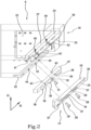
- a connecting screw 31 which passes through a through hole 32 made in the intermediate component 27 and engages in a threaded hole 33 made in the base component 22.
- An access hole 34 may be formed on the containment element 24 for accessing the connecting screw 31 even when the containment element 24 is already fixed to the intermediate component 27.
- the assembly formed by the containment element 24 and by the intermediate component 27, already correctly positioned relative to each other, may now be fixed to the base component 22 owing to the connecting screw 31.
- Reference means are further provided for mounting the intermediate component 27 in a predetermined position on the base component 22.
- the reference means may comprise a pair of pins 43 fixed relative to the intermediate component 27, suitable for engaging in corresponding holes 44 of the base component 22.
- the assembly formed by the containment element 24 and by the intermediate component 27 may be mounted in a repeatable manner on the base component 22.
- the containment element 24 can be replaced quickly and easily when necessary.
- the adjustment operations on the containment element 24 can be performed outside the welding apparatus, mounting the containment element 24 on the intermediate component 27, in such a way as to prevent extended machine stoppages.
- the profiled bar 2 and the further profiled bar 3 are prepared beforehand, by cutting them to the desired length and forming end sections 18 according to the desired shape.
- the profiled bars 2, 3 are cut at 45° relative to the corresponding longitudinal axis Z, so as to form end sections 18 each of which lies in a plane at an angle of 45° to the longitudinal axis Z of the respective profiled bar 2, 3.
- the seats 45 are made on the first face 10 and on the second face 11 of each profiled bar 2, 3.
- the seats 45 have the function of receiving the material of the welding bead which will be formed in a joining zone between the profiled bars 2, 3 respectively on the first faces 10 and on the second faces 11.
- the seats 45 are formed upstream of the welding head 1, in particular upstream of the welding apparatus in which the welding head 1 is included. This avoids complicating the structure of the welding head 1 and/or the welding apparatus, which does not need to comprise complicated material removal devices, nor devices for removing chippings.
- the profiled bar 2 and the further profiled bar 3 are then positioned on the welding head 1.
- the profiled bar 2 is rested on the lower supporting element 13 of the supporting device 6, whilst the further profiled bar 3 is rested on the lower supporting element 13 of the further supporting device 8.
- Both the upper supporting element 16 of the supporting device 6 and the upper supporting element 16 of the further supporting device 8 are still in the disengagement position, that is to say, in the position in which the profiled bars 2, 3 are free to move relative to the upper supporting element 16 and to the lower supporting element 13 of the corresponding supporting device 6, 8.
- the abutment element 19 guarantees the correct positioning of the profiled bars 2, 3, between which it is interposed. For that purpose, the end sections 18 of the bar 2 and of the further profiled bar 3 are brought to abut against the contact element 19, on opposite sides of the latter.
- a positioning step is thus carried out in which the profiled bars 2, 3 are positioned in a repetitive manner on the welding head 1, by arranging them in a predetermined position relative to the abutment element 19, with which the end sections 18 are in contact.
- the containment elements 24 (whose ends are normally in a more advanced position than the end sections 18) are moved backwards along the profiled bar 2 or the further bar 3. This occurs because the abutment element 19 exerts a sufficient force on the containment elements 24 to overcome the force of the elastic elements 23.
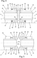
- the upper supporting element 16 of the supporting device 6 is moved in the direction D1 shown in Figure 4 and displaced towards the lower supporting element 13 of the supporting device 6, until reaching the clamping position, in which the end portion 7 of the profiled bar 2 is locked on the supporting device 6.
- the further profiled bar 3 is locked between the lower supporting element 13 and the upper supporting element 16 of the further supporting device 8, by moving the upper supporting element 16 in the direction D2 until reaching the clamping position.
- the supporting device 6 and the further supporting device 8 are now moved away from each other to move them to the position of Figure 5 .
- the end sections 18 of the profiled bar 2 and of the further profiled bar 3 disengage from the abutment element 19, which can thus be moved away from the profiled bars 2, 3 and repositioned in the casing 5.
- the step described above with reference to Figure 5 can be defined as a step of locking the profiled bars 2, 3 on the corresponding supporting device 6, 8, moving away the profiled bars 2, 3 from each other and removing the abutment element 19.
- the heating element 20 is moved outside the casing 5 and inserted between the profiled bar 2 and the further profiled bar 3.
- the driving means associated with the supporting device 6 move the profiled bar 2 for bringing the end section 18 of the profiled bar 2 into contact with the heating element 20.
- the further driving means associated with the further supporting device 8 bring the end section 18 of the further profiled bar 3 into contact with the heating element 20.
- the heating element 20 is heated to a predetermined temperature, so as to transfer heat to the end sections 18 of the profiled bar 2 and of the further bar 3 with which it is in contact.
- the material which forms the bar 2 and the further profiled bar 3 is therefore brought to a relatively high temperature and consequently softened close to the end sections 18.
- the driving means acting on the supporting device 6 further push the profiled bar 2 towards the heating element 20, moving the profiled bar 2 with a controlled speed.
- the profiled bar 2 is consequently further moved close to the heating element 20, in such a way as to soften a stretch of profiled bar 2 having a predetermined length, measured starting from the original end section 18.
- the further driving means associated with the further supporting device 8 push the further profiled bar 3 towards the heating element 20, by moving the further profiled bar 3 with a controlled speed.
- the step described above may be defined as a step of softening the material which forms the profiled bar 2 and the further profiled bar 3 close to the end sections 18.
- the containing elements 24 are pushed in contact with the heating element 20.
- the containment elements 24 prevent the softened material from flowing above the first face 10 and below the second face 11.
- the protuberances 25 are housed in the seats 45 of the profiled bar 2 and in the further profiled bar 3.
- the protuberances 25 move the softened material towards the inside of the profiled bars 2, 3, that is to say, towards the longitudinal axis Z of the profiled bar 2 and of the further profiled bar 3.
- the protuberances 25 act as deflectors which divert the softened material, moving it away from the first face 10 and from the second face 11 and moving it towards the inside of the profiled bars 2, 3, which are hollow inside.
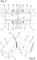
- the supporting device 6 and the further supporting device 8 move away from the heating element 20. Consequently, the profiled bars 2, 3 detach from the heating element 20, which may now be withdrawn inside the casing 5. Subsequently, the supporting device 6 and the further supporting device 8, owing to the corresponding driving means and further driving means, push the profiled bar 2 and the further profiled bar 3 against each other, as shown in Figure 7 . The end sections 18 of the profiled bar 2 and of the further profiled bar 3 are thus brought into contact with each other.
- the profiled bar 2 and the further profiled bar 3 are further moved towards each other. In that way, a pressure is applied on the profiled bar 2 and on the further profiled bar 3 such as to weld the profiled bar 2 to the further profiled bar 3.
- the welding is performed by joining of portions of softened material close to the end sections 18.
- this step which may be defined as a welding step, the containment elements 24 are pushed into contact with each other and are arranged in a position of mutual contact.
- the protuberances 25 are adjacent to each other and together form a penetrating portion 46 which penetrates into the portions of softened material already in contact with each other.
- the welding step ends.
- the product obtained by joining the profiled bar 2 and the further profiled bar 3 can now be removed from the welding head 1.
- the containment elements 24 make it possible to obtain joining zones having an aesthetically pleasing appearance, in which the welding bead is practically not visible from the outside.
Landscapes
- Engineering & Computer Science (AREA)
- Mechanical Engineering (AREA)
- Lining Or Joining Of Plastics Or The Like (AREA)
- Pressure Welding/Diffusion-Bonding (AREA)
- Butt Welding And Welding Of Specific Article (AREA)
Applications Claiming Priority (1)
| Application Number | Priority Date | Filing Date | Title |
|---|---|---|---|
| IT102020000030410A IT202000030410A1 (it) | 2020-12-10 | 2020-12-10 | Dispositivo di supporto per supportare una barra profilata in un apparato di saldatura. |
Publications (2)
| Publication Number | Publication Date |
|---|---|
| EP4019227A1 EP4019227A1 (en) | 2022-06-29 |
| EP4019227B1 true EP4019227B1 (en) | 2025-07-09 |
Family
ID=74759342
Family Applications (1)
| Application Number | Title | Priority Date | Filing Date |
|---|---|---|---|
| EP21208392.7A Active EP4019227B1 (en) | 2020-12-10 | 2021-11-16 | A supporting device for supporting a profiled bar in a welding apparatus |
Country Status (5)
| Country | Link |
|---|---|
| EP (1) | EP4019227B1 (pl) |
| ES (1) | ES3038080T3 (pl) |
| IT (1) | IT202000030410A1 (pl) |
| PL (1) | PL4019227T3 (pl) |
| PT (1) | PT4019227T (pl) |
Families Citing this family (1)
| Publication number | Priority date | Publication date | Assignee | Title |
|---|---|---|---|---|
| GB2640405A (en) * | 2024-04-15 | 2025-10-22 | Kaban Makina Sanayi Ve Ticaret Ltd Sirketi | Welding device for PVC profiles |
Family Cites Families (2)
| Publication number | Priority date | Publication date | Assignee | Title |
|---|---|---|---|---|
| DE102016102240A1 (de) * | 2016-02-10 | 2017-08-10 | Rotox Besitz-Und Verwaltungsgesellschaft Mbh | Vorrichtung zum Verbinden von Profilstücken |
| IT201800002154A1 (it) | 2018-01-30 | 2019-07-30 | Emmegi Spa | Apparato per saldare barre profilate. |
-
2020
- 2020-12-10 IT IT102020000030410A patent/IT202000030410A1/it unknown
-
2021
- 2021-11-16 EP EP21208392.7A patent/EP4019227B1/en active Active
- 2021-11-16 PT PT212083927T patent/PT4019227T/pt unknown
- 2021-11-16 ES ES21208392T patent/ES3038080T3/es active Active
- 2021-11-16 PL PL21208392.7T patent/PL4019227T3/pl unknown
Also Published As
| Publication number | Publication date |
|---|---|
| PT4019227T (pt) | 2025-08-21 |
| ES3038080T3 (en) | 2025-10-09 |
| PL4019227T3 (pl) | 2025-11-17 |
| EP4019227A1 (en) | 2022-06-29 |
| IT202000030410A1 (it) | 2022-06-10 |
Similar Documents
| Publication | Publication Date | Title |
|---|---|---|
| EP4019227B1 (en) | A supporting device for supporting a profiled bar in a welding apparatus | |
| CA2381529C (en) | Multiple-head friction welding method | |
| US7343950B2 (en) | Method and apparatus for vibration welding of thermoplastic components | |
| US4239574A (en) | Process and apparatus for the welding of synthetic resin structures | |
| EP3517279B1 (en) | An apparatus for welding profiled bars | |
| CA2780531C (en) | Welding apparatus for conveyor belts and method | |
| US11491736B2 (en) | Machine for welding profiled elements | |
| US6273988B1 (en) | Method for welding plastic members | |
| US5439546A (en) | Process for welding profiles, in particular plastic profiles | |
| WO1998047692A1 (en) | Clamping head for use in joining plastic extrusions and method thereof | |
| CN109476093B (zh) | 用于密封塑料成型元件的机器 | |
| CA1303962C (en) | Venetian blind ladder means and method and apparatus for assembling a blind | |
| EP2179837B1 (en) | Profile joining system | |
| KR20040026499A (ko) | 시스템 창호의 복합 가공장치 | |
| EP3507080B1 (en) | Process for the realization of counter- mould elements for the containment of welding bead of plastic profiled elements | |
| EP0531682B1 (de) | Vorrichtung zum Verschweissen von Profilen aus Kunststoff | |
| EP0811463B1 (en) | Mobile rest equipment for a workpiece with variable distance support arms for automatic production lines | |
| RU2573476C2 (ru) | Устройство и способ для сваривания профилированных деталей | |
| US4328847A (en) | Universal woodworking machine | |
| EP3456496B1 (en) | A method and apparatus for working profiled members | |
| JP7481917B2 (ja) | 取付具、開口部装置及び取り付け方法 | |
| CA2439552C (en) | Method and apparatus for vibration welding of thermoplastic components | |
| WO2023126734A1 (en) | Process and machine for the reverse-butt welding of profiled elements made of plastic material | |
| KR200328213Y1 (ko) | 비드 제거장치용 칼날조립체의 측면사상커터 조립구조 | |
| GB2640405A (en) | Welding device for PVC profiles |
Legal Events
| Date | Code | Title | Description |
|---|---|---|---|
| PUAI | Public reference made under article 153(3) epc to a published international application that has entered the european phase |
Free format text: ORIGINAL CODE: 0009012 |
|
| STAA | Information on the status of an ep patent application or granted ep patent |
Free format text: STATUS: THE APPLICATION HAS BEEN PUBLISHED |
|
| AK | Designated contracting states |
Kind code of ref document: A1 Designated state(s): AL AT BE BG CH CY CZ DE DK EE ES FI FR GB GR HR HU IE IS IT LI LT LU LV MC MK MT NL NO PL PT RO RS SE SI SK SM TR |
|
| STAA | Information on the status of an ep patent application or granted ep patent |
Free format text: STATUS: REQUEST FOR EXAMINATION WAS MADE |
|
| 17P | Request for examination filed |
Effective date: 20221223 |
|
| RBV | Designated contracting states (corrected) |
Designated state(s): AL AT BE BG CH CY CZ DE DK EE ES FI FR GB GR HR HU IE IS IT LI LT LU LV MC MK MT NL NO PL PT RO RS SE SI SK SM TR |
|
| P01 | Opt-out of the competence of the unified patent court (upc) registered |
Effective date: 20230601 |
|
| GRAP | Despatch of communication of intention to grant a patent |
Free format text: ORIGINAL CODE: EPIDOSNIGR1 |
|
| STAA | Information on the status of an ep patent application or granted ep patent |
Free format text: STATUS: GRANT OF PATENT IS INTENDED |
|
| RIC1 | Information provided on ipc code assigned before grant |
Ipc: B29K 27/06 20060101ALN20250131BHEP Ipc: E06B 3/96 20060101ALN20250131BHEP Ipc: B29C 65/78 20060101ALI20250131BHEP Ipc: B29C 65/20 20060101AFI20250131BHEP |
|
| INTG | Intention to grant announced |
Effective date: 20250227 |
|
| GRAS | Grant fee paid |
Free format text: ORIGINAL CODE: EPIDOSNIGR3 |
|
| GRAA | (expected) grant |
Free format text: ORIGINAL CODE: 0009210 |
|
| STAA | Information on the status of an ep patent application or granted ep patent |
Free format text: STATUS: THE PATENT HAS BEEN GRANTED |
|
| AK | Designated contracting states |
Kind code of ref document: B1 Designated state(s): AL AT BE BG CH CY CZ DE DK EE ES FI FR GB GR HR HU IE IS IT LI LT LU LV MC MK MT NL NO PL PT RO RS SE SI SK SM TR |
|
| REG | Reference to a national code |
Ref country code: GB Ref legal event code: FG4D |
|
| REG | Reference to a national code |
Ref country code: CH Ref legal event code: EP |
|
| REG | Reference to a national code |
Ref country code: IE Ref legal event code: FG4D |
|
| REG | Reference to a national code |
Ref country code: DE Ref legal event code: R096 Ref document number: 602021033707 Country of ref document: DE |
|
| REG | Reference to a national code |
Ref country code: PT Ref legal event code: SC4A Ref document number: 4019227 Country of ref document: PT Date of ref document: 20250821 Kind code of ref document: T Free format text: AVAILABILITY OF NATIONAL TRANSLATION Effective date: 20250818 |
|
| REG | Reference to a national code |
Ref country code: ES Ref legal event code: FG2A Ref document number: 3038080 Country of ref document: ES Kind code of ref document: T3 Effective date: 20251009 |
|
| REG | Reference to a national code |
Ref country code: NL Ref legal event code: MP Effective date: 20250709 |
|
| PGFP | Annual fee paid to national office [announced via postgrant information from national office to epo] |
Ref country code: PT Payment date: 20251027 Year of fee payment: 5 |
|
| PG25 | Lapsed in a contracting state [announced via postgrant information from national office to epo] |
Ref country code: NL Free format text: LAPSE BECAUSE OF FAILURE TO SUBMIT A TRANSLATION OF THE DESCRIPTION OR TO PAY THE FEE WITHIN THE PRESCRIBED TIME-LIMIT Effective date: 20250709 |
|
| REG | Reference to a national code |
Ref country code: AT Ref legal event code: MK05 Ref document number: 1811489 Country of ref document: AT Kind code of ref document: T Effective date: 20250709 |
|
| PG25 | Lapsed in a contracting state [announced via postgrant information from national office to epo] |
Ref country code: IS Free format text: LAPSE BECAUSE OF FAILURE TO SUBMIT A TRANSLATION OF THE DESCRIPTION OR TO PAY THE FEE WITHIN THE PRESCRIBED TIME-LIMIT Effective date: 20251109 |
|
| PGFP | Annual fee paid to national office [announced via postgrant information from national office to epo] |
Ref country code: DE Payment date: 20251126 Year of fee payment: 5 |
|
| PG25 | Lapsed in a contracting state [announced via postgrant information from national office to epo] |
Ref country code: NO Free format text: LAPSE BECAUSE OF FAILURE TO SUBMIT A TRANSLATION OF THE DESCRIPTION OR TO PAY THE FEE WITHIN THE PRESCRIBED TIME-LIMIT Effective date: 20251009 |
|
| REG | Reference to a national code |
Ref country code: LT Ref legal event code: MG9D |
|
| PG25 | Lapsed in a contracting state [announced via postgrant information from national office to epo] |
Ref country code: AT Free format text: LAPSE BECAUSE OF FAILURE TO SUBMIT A TRANSLATION OF THE DESCRIPTION OR TO PAY THE FEE WITHIN THE PRESCRIBED TIME-LIMIT Effective date: 20250709 |
|
| PG25 | Lapsed in a contracting state [announced via postgrant information from national office to epo] |
Ref country code: FI Free format text: LAPSE BECAUSE OF FAILURE TO SUBMIT A TRANSLATION OF THE DESCRIPTION OR TO PAY THE FEE WITHIN THE PRESCRIBED TIME-LIMIT Effective date: 20250709 |
|
| PGFP | Annual fee paid to national office [announced via postgrant information from national office to epo] |
Ref country code: IT Payment date: 20251127 Year of fee payment: 5 |
|
| PG25 | Lapsed in a contracting state [announced via postgrant information from national office to epo] |
Ref country code: HR Free format text: LAPSE BECAUSE OF FAILURE TO SUBMIT A TRANSLATION OF THE DESCRIPTION OR TO PAY THE FEE WITHIN THE PRESCRIBED TIME-LIMIT Effective date: 20250709 |
|
| PGFP | Annual fee paid to national office [announced via postgrant information from national office to epo] |
Ref country code: FR Payment date: 20251124 Year of fee payment: 5 |
|
| PG25 | Lapsed in a contracting state [announced via postgrant information from national office to epo] |
Ref country code: GR Free format text: LAPSE BECAUSE OF FAILURE TO SUBMIT A TRANSLATION OF THE DESCRIPTION OR TO PAY THE FEE WITHIN THE PRESCRIBED TIME-LIMIT Effective date: 20251010 |
|
| PGFP | Annual fee paid to national office [announced via postgrant information from national office to epo] |
Ref country code: TR Payment date: 20251030 Year of fee payment: 5 |
|
| PG25 | Lapsed in a contracting state [announced via postgrant information from national office to epo] |
Ref country code: SE Free format text: LAPSE BECAUSE OF FAILURE TO SUBMIT A TRANSLATION OF THE DESCRIPTION OR TO PAY THE FEE WITHIN THE PRESCRIBED TIME-LIMIT Effective date: 20250709 |
|
| PG25 | Lapsed in a contracting state [announced via postgrant information from national office to epo] |
Ref country code: LV Free format text: LAPSE BECAUSE OF FAILURE TO SUBMIT A TRANSLATION OF THE DESCRIPTION OR TO PAY THE FEE WITHIN THE PRESCRIBED TIME-LIMIT Effective date: 20250709 |
|
| PG25 | Lapsed in a contracting state [announced via postgrant information from national office to epo] |
Ref country code: BG Free format text: LAPSE BECAUSE OF FAILURE TO SUBMIT A TRANSLATION OF THE DESCRIPTION OR TO PAY THE FEE WITHIN THE PRESCRIBED TIME-LIMIT Effective date: 20250709 |
|
| PGFP | Annual fee paid to national office [announced via postgrant information from national office to epo] |
Ref country code: PL Payment date: 20251023 Year of fee payment: 5 |
|
| PG25 | Lapsed in a contracting state [announced via postgrant information from national office to epo] |
Ref country code: RS Free format text: LAPSE BECAUSE OF FAILURE TO SUBMIT A TRANSLATION OF THE DESCRIPTION OR TO PAY THE FEE WITHIN THE PRESCRIBED TIME-LIMIT Effective date: 20251009 |
|
| PGFP | Annual fee paid to national office [announced via postgrant information from national office to epo] |
Ref country code: ES Payment date: 20251209 Year of fee payment: 5 |
|
| PG25 | Lapsed in a contracting state [announced via postgrant information from national office to epo] |
Ref country code: RO Free format text: LAPSE BECAUSE OF FAILURE TO SUBMIT A TRANSLATION OF THE DESCRIPTION OR TO PAY THE FEE WITHIN THE PRESCRIBED TIME-LIMIT Effective date: 20250709 |
|
| PG25 | Lapsed in a contracting state [announced via postgrant information from national office to epo] |
Ref country code: SM Free format text: LAPSE BECAUSE OF FAILURE TO SUBMIT A TRANSLATION OF THE DESCRIPTION OR TO PAY THE FEE WITHIN THE PRESCRIBED TIME-LIMIT Effective date: 20250709 |
|
| PG25 | Lapsed in a contracting state [announced via postgrant information from national office to epo] |
Ref country code: DK Free format text: LAPSE BECAUSE OF FAILURE TO SUBMIT A TRANSLATION OF THE DESCRIPTION OR TO PAY THE FEE WITHIN THE PRESCRIBED TIME-LIMIT Effective date: 20250709 |