EP4019233B1 - Procédé de fabrication d'un faisceau de fibres de carbone adaptable - Google Patents
Procédé de fabrication d'un faisceau de fibres de carbone adaptable Download PDFInfo
- Publication number
- EP4019233B1 EP4019233B1 EP20216420.8A EP20216420A EP4019233B1 EP 4019233 B1 EP4019233 B1 EP 4019233B1 EP 20216420 A EP20216420 A EP 20216420A EP 4019233 B1 EP4019233 B1 EP 4019233B1
- Authority
- EP
- European Patent Office
- Prior art keywords
- carbon
- fibre
- adaptable
- cast
- rotor blade
- Prior art date
- Legal status (The legal status is an assumption and is not a legal conclusion. Google has not performed a legal analysis and makes no representation as to the accuracy of the status listed.)
- Active
Links
Images



Classifications
-
- B—PERFORMING OPERATIONS; TRANSPORTING
- B29—WORKING OF PLASTICS; WORKING OF SUBSTANCES IN A PLASTIC STATE IN GENERAL
- B29C—SHAPING OR JOINING OF PLASTICS; SHAPING OF MATERIAL IN A PLASTIC STATE, NOT OTHERWISE PROVIDED FOR; AFTER-TREATMENT OF THE SHAPED PRODUCTS, e.g. REPAIRING
- B29C37/00—Component parts, details, accessories or auxiliary operations, not covered by group B29C33/00 or B29C35/00
- B29C37/0078—Measures or configurations for obtaining anchoring effects in the contact areas between layers
- B29C37/0082—Mechanical anchoring
-
- B—PERFORMING OPERATIONS; TRANSPORTING
- B29—WORKING OF PLASTICS; WORKING OF SUBSTANCES IN A PLASTIC STATE IN GENERAL
- B29C—SHAPING OR JOINING OF PLASTICS; SHAPING OF MATERIAL IN A PLASTIC STATE, NOT OTHERWISE PROVIDED FOR; AFTER-TREATMENT OF THE SHAPED PRODUCTS, e.g. REPAIRING
- B29C70/00—Shaping composites, i.e. plastics material comprising reinforcements, fillers or preformed parts, e.g. inserts
- B29C70/04—Shaping composites, i.e. plastics material comprising reinforcements, fillers or preformed parts, e.g. inserts comprising reinforcements only, e.g. self-reinforcing plastics
- B29C70/28—Shaping operations therefor
- B29C70/40—Shaping or impregnating by compression not applied
- B29C70/50—Shaping or impregnating by compression not applied for producing articles of indefinite length, e.g. prepregs, sheet moulding compounds [SMC] or cross moulding compounds [XMC]
- B29C70/52—Pultrusion, i.e. forming and compressing by continuously pulling through a die
- B29C70/523—Pultrusion, i.e. forming and compressing by continuously pulling through a die and impregnating the reinforcement in the die
-
- B—PERFORMING OPERATIONS; TRANSPORTING
- B29—WORKING OF PLASTICS; WORKING OF SUBSTANCES IN A PLASTIC STATE IN GENERAL
- B29C—SHAPING OR JOINING OF PLASTICS; SHAPING OF MATERIAL IN A PLASTIC STATE, NOT OTHERWISE PROVIDED FOR; AFTER-TREATMENT OF THE SHAPED PRODUCTS, e.g. REPAIRING
- B29C70/00—Shaping composites, i.e. plastics material comprising reinforcements, fillers or preformed parts, e.g. inserts
- B29C70/04—Shaping composites, i.e. plastics material comprising reinforcements, fillers or preformed parts, e.g. inserts comprising reinforcements only, e.g. self-reinforcing plastics
- B29C70/28—Shaping operations therefor
- B29C70/40—Shaping or impregnating by compression not applied
- B29C70/42—Shaping or impregnating by compression not applied for producing articles of definite length, i.e. discrete articles
- B29C70/44—Shaping or impregnating by compression not applied for producing articles of definite length, i.e. discrete articles using isostatic pressure, e.g. pressure difference-moulding, vacuum bag-moulding, autoclave-moulding or expanding rubber-moulding
- B29C70/443—Shaping or impregnating by compression not applied for producing articles of definite length, i.e. discrete articles using isostatic pressure, e.g. pressure difference-moulding, vacuum bag-moulding, autoclave-moulding or expanding rubber-moulding and impregnating by vacuum or injection
-
- B—PERFORMING OPERATIONS; TRANSPORTING
- B29—WORKING OF PLASTICS; WORKING OF SUBSTANCES IN A PLASTIC STATE IN GENERAL
- B29C—SHAPING OR JOINING OF PLASTICS; SHAPING OF MATERIAL IN A PLASTIC STATE, NOT OTHERWISE PROVIDED FOR; AFTER-TREATMENT OF THE SHAPED PRODUCTS, e.g. REPAIRING
- B29C70/00—Shaping composites, i.e. plastics material comprising reinforcements, fillers or preformed parts, e.g. inserts
- B29C70/04—Shaping composites, i.e. plastics material comprising reinforcements, fillers or preformed parts, e.g. inserts comprising reinforcements only, e.g. self-reinforcing plastics
- B29C70/28—Shaping operations therefor
- B29C70/40—Shaping or impregnating by compression not applied
- B29C70/50—Shaping or impregnating by compression not applied for producing articles of indefinite length, e.g. prepregs, sheet moulding compounds [SMC] or cross moulding compounds [XMC]
- B29C70/52—Pultrusion, i.e. forming and compressing by continuously pulling through a die
- B29C70/525—Component parts, details or accessories; Auxiliary operations
-
- B—PERFORMING OPERATIONS; TRANSPORTING
- B29—WORKING OF PLASTICS; WORKING OF SUBSTANCES IN A PLASTIC STATE IN GENERAL
- B29C—SHAPING OR JOINING OF PLASTICS; SHAPING OF MATERIAL IN A PLASTIC STATE, NOT OTHERWISE PROVIDED FOR; AFTER-TREATMENT OF THE SHAPED PRODUCTS, e.g. REPAIRING
- B29C70/00—Shaping composites, i.e. plastics material comprising reinforcements, fillers or preformed parts, e.g. inserts
- B29C70/68—Shaping composites, i.e. plastics material comprising reinforcements, fillers or preformed parts, e.g. inserts by incorporating or moulding on preformed parts, e.g. inserts or layers, e.g. foam blocks
- B29C70/681—Component parts, details or accessories; Auxiliary operations
- B29C70/682—Preformed parts characterised by their structure, e.g. form
-
- B—PERFORMING OPERATIONS; TRANSPORTING
- B29—WORKING OF PLASTICS; WORKING OF SUBSTANCES IN A PLASTIC STATE IN GENERAL
- B29C—SHAPING OR JOINING OF PLASTICS; SHAPING OF MATERIAL IN A PLASTIC STATE, NOT OTHERWISE PROVIDED FOR; AFTER-TREATMENT OF THE SHAPED PRODUCTS, e.g. REPAIRING
- B29C70/00—Shaping composites, i.e. plastics material comprising reinforcements, fillers or preformed parts, e.g. inserts
- B29C70/68—Shaping composites, i.e. plastics material comprising reinforcements, fillers or preformed parts, e.g. inserts by incorporating or moulding on preformed parts, e.g. inserts or layers, e.g. foam blocks
- B29C70/84—Shaping composites, i.e. plastics material comprising reinforcements, fillers or preformed parts, e.g. inserts by incorporating or moulding on preformed parts, e.g. inserts or layers, e.g. foam blocks by moulding material on preformed parts to be joined
-
- B—PERFORMING OPERATIONS; TRANSPORTING
- B29—WORKING OF PLASTICS; WORKING OF SUBSTANCES IN A PLASTIC STATE IN GENERAL
- B29C—SHAPING OR JOINING OF PLASTICS; SHAPING OF MATERIAL IN A PLASTIC STATE, NOT OTHERWISE PROVIDED FOR; AFTER-TREATMENT OF THE SHAPED PRODUCTS, e.g. REPAIRING
- B29C70/00—Shaping composites, i.e. plastics material comprising reinforcements, fillers or preformed parts, e.g. inserts
- B29C70/68—Shaping composites, i.e. plastics material comprising reinforcements, fillers or preformed parts, e.g. inserts by incorporating or moulding on preformed parts, e.g. inserts or layers, e.g. foam blocks
- B29C70/86—Incorporated in coherent impregnated reinforcing layers, e.g. by winding
- B29C70/865—Incorporated in coherent impregnated reinforcing layers, e.g. by winding completely encapsulated
-
- B—PERFORMING OPERATIONS; TRANSPORTING
- B29—WORKING OF PLASTICS; WORKING OF SUBSTANCES IN A PLASTIC STATE IN GENERAL
- B29D—PRODUCING PARTICULAR ARTICLES FROM PLASTICS OR FROM SUBSTANCES IN A PLASTIC STATE
- B29D99/00—Subject matter not provided for in other groups of this subclass
- B29D99/0025—Producing blades or the like, e.g. blades for turbines, propellers, or wings
- B29D99/0028—Producing blades or the like, e.g. blades for turbines, propellers, or wings hollow blades
-
- B—PERFORMING OPERATIONS; TRANSPORTING
- B29—WORKING OF PLASTICS; WORKING OF SUBSTANCES IN A PLASTIC STATE IN GENERAL
- B29C—SHAPING OR JOINING OF PLASTICS; SHAPING OF MATERIAL IN A PLASTIC STATE, NOT OTHERWISE PROVIDED FOR; AFTER-TREATMENT OF THE SHAPED PRODUCTS, e.g. REPAIRING
- B29C70/00—Shaping composites, i.e. plastics material comprising reinforcements, fillers or preformed parts, e.g. inserts
- B29C70/04—Shaping composites, i.e. plastics material comprising reinforcements, fillers or preformed parts, e.g. inserts comprising reinforcements only, e.g. self-reinforcing plastics
- B29C70/28—Shaping operations therefor
- B29C70/40—Shaping or impregnating by compression not applied
- B29C70/50—Shaping or impregnating by compression not applied for producing articles of indefinite length, e.g. prepregs, sheet moulding compounds [SMC] or cross moulding compounds [XMC]
- B29C70/52—Pultrusion, i.e. forming and compressing by continuously pulling through a die
-
- B—PERFORMING OPERATIONS; TRANSPORTING
- B29—WORKING OF PLASTICS; WORKING OF SUBSTANCES IN A PLASTIC STATE IN GENERAL
- B29K—INDEXING SCHEME ASSOCIATED WITH SUBCLASSES B29B, B29C OR B29D, RELATING TO MOULDING MATERIALS OR TO MATERIALS FOR MOULDS, REINFORCEMENTS, FILLERS OR PREFORMED PARTS, e.g. INSERTS
- B29K2307/00—Use of elements other than metals as reinforcement
- B29K2307/04—Carbon
-
- B—PERFORMING OPERATIONS; TRANSPORTING
- B29—WORKING OF PLASTICS; WORKING OF SUBSTANCES IN A PLASTIC STATE IN GENERAL
- B29K—INDEXING SCHEME ASSOCIATED WITH SUBCLASSES B29B, B29C OR B29D, RELATING TO MOULDING MATERIALS OR TO MATERIALS FOR MOULDS, REINFORCEMENTS, FILLERS OR PREFORMED PARTS, e.g. INSERTS
- B29K2309/00—Use of inorganic materials not provided for in groups B29K2303/00 - B29K2307/00, as reinforcement
- B29K2309/08—Glass
-
- B—PERFORMING OPERATIONS; TRANSPORTING
- B29—WORKING OF PLASTICS; WORKING OF SUBSTANCES IN A PLASTIC STATE IN GENERAL
- B29K—INDEXING SCHEME ASSOCIATED WITH SUBCLASSES B29B, B29C OR B29D, RELATING TO MOULDING MATERIALS OR TO MATERIALS FOR MOULDS, REINFORCEMENTS, FILLERS OR PREFORMED PARTS, e.g. INSERTS
- B29K2995/00—Properties of moulding materials, reinforcements, fillers, preformed parts or moulds
- B29K2995/0037—Other properties
- B29K2995/005—Oriented
- B29K2995/0053—Oriented bi-axially
-
- B—PERFORMING OPERATIONS; TRANSPORTING
- B29—WORKING OF PLASTICS; WORKING OF SUBSTANCES IN A PLASTIC STATE IN GENERAL
- B29L—INDEXING SCHEME ASSOCIATED WITH SUBCLASS B29C, RELATING TO PARTICULAR ARTICLES
- B29L2031/00—Other particular articles
- B29L2031/08—Blades for rotors, stators, fans, turbines or the like, e.g. screw propellers
- B29L2031/082—Blades, e.g. for helicopters
- B29L2031/085—Wind turbine blades
-
- F—MECHANICAL ENGINEERING; LIGHTING; HEATING; WEAPONS; BLASTING
- F03—MACHINES OR ENGINES FOR LIQUIDS; WIND, SPRING, OR WEIGHT MOTORS; PRODUCING MECHANICAL POWER OR A REACTIVE PROPULSIVE THRUST, NOT OTHERWISE PROVIDED FOR
- F03D—WIND MOTORS
- F03D1/00—Wind motors with rotation axis substantially parallel to the air flow entering the rotor
- F03D1/06—Rotors
- F03D1/065—Rotors characterised by their construction elements
- F03D1/0675—Rotors characterised by their construction elements of the blades
-
- F—MECHANICAL ENGINEERING; LIGHTING; HEATING; WEAPONS; BLASTING
- F05—INDEXING SCHEMES RELATING TO ENGINES OR PUMPS IN VARIOUS SUBCLASSES OF CLASSES F01-F04
- F05B—INDEXING SCHEME RELATING TO WIND, SPRING, WEIGHT, INERTIA OR LIKE MOTORS, TO MACHINES OR ENGINES FOR LIQUIDS COVERED BY SUBCLASSES F03B, F03D AND F03G
- F05B2230/00—Manufacture
- F05B2230/20—Manufacture essentially without removing material
- F05B2230/21—Manufacture essentially without removing material by casting
-
- F—MECHANICAL ENGINEERING; LIGHTING; HEATING; WEAPONS; BLASTING
- F05—INDEXING SCHEMES RELATING TO ENGINES OR PUMPS IN VARIOUS SUBCLASSES OF CLASSES F01-F04
- F05B—INDEXING SCHEME RELATING TO WIND, SPRING, WEIGHT, INERTIA OR LIKE MOTORS, TO MACHINES OR ENGINES FOR LIQUIDS COVERED BY SUBCLASSES F03B, F03D AND F03G
- F05B2280/00—Materials; Properties thereof
- F05B2280/20—Inorganic materials, e.g. non-metallic materials
- F05B2280/2001—Glass
-
- F—MECHANICAL ENGINEERING; LIGHTING; HEATING; WEAPONS; BLASTING
- F05—INDEXING SCHEMES RELATING TO ENGINES OR PUMPS IN VARIOUS SUBCLASSES OF CLASSES F01-F04
- F05B—INDEXING SCHEME RELATING TO WIND, SPRING, WEIGHT, INERTIA OR LIKE MOTORS, TO MACHINES OR ENGINES FOR LIQUIDS COVERED BY SUBCLASSES F03B, F03D AND F03G
- F05B2280/00—Materials; Properties thereof
- F05B2280/20—Inorganic materials, e.g. non-metallic materials
- F05B2280/2006—Carbon, e.g. graphite
-
- F—MECHANICAL ENGINEERING; LIGHTING; HEATING; WEAPONS; BLASTING
- F05—INDEXING SCHEMES RELATING TO ENGINES OR PUMPS IN VARIOUS SUBCLASSES OF CLASSES F01-F04
- F05B—INDEXING SCHEME RELATING TO WIND, SPRING, WEIGHT, INERTIA OR LIKE MOTORS, TO MACHINES OR ENGINES FOR LIQUIDS COVERED BY SUBCLASSES F03B, F03D AND F03G
- F05B2280/00—Materials; Properties thereof
- F05B2280/60—Properties or characteristics given to material by treatment or manufacturing
- F05B2280/6003—Composites; e.g. fibre-reinforced
-
- Y—GENERAL TAGGING OF NEW TECHNOLOGICAL DEVELOPMENTS; GENERAL TAGGING OF CROSS-SECTIONAL TECHNOLOGIES SPANNING OVER SEVERAL SECTIONS OF THE IPC; TECHNICAL SUBJECTS COVERED BY FORMER USPC CROSS-REFERENCE ART COLLECTIONS [XRACs] AND DIGESTS
- Y02—TECHNOLOGIES OR APPLICATIONS FOR MITIGATION OR ADAPTATION AGAINST CLIMATE CHANGE
- Y02E—REDUCTION OF GREENHOUSE GAS [GHG] EMISSIONS, RELATED TO ENERGY GENERATION, TRANSMISSION OR DISTRIBUTION
- Y02E10/00—Energy generation through renewable energy sources
- Y02E10/70—Wind energy
- Y02E10/72—Wind turbines with rotation axis in wind direction
-
- Y—GENERAL TAGGING OF NEW TECHNOLOGICAL DEVELOPMENTS; GENERAL TAGGING OF CROSS-SECTIONAL TECHNOLOGIES SPANNING OVER SEVERAL SECTIONS OF THE IPC; TECHNICAL SUBJECTS COVERED BY FORMER USPC CROSS-REFERENCE ART COLLECTIONS [XRACs] AND DIGESTS
- Y02—TECHNOLOGIES OR APPLICATIONS FOR MITIGATION OR ADAPTATION AGAINST CLIMATE CHANGE
- Y02P—CLIMATE CHANGE MITIGATION TECHNOLOGIES IN THE PRODUCTION OR PROCESSING OF GOODS
- Y02P70/00—Climate change mitigation technologies in the production process for final industrial or consumer products
- Y02P70/50—Manufacturing or production processes characterised by the final manufactured product
Definitions
- the invention describes a method of manufacturing an adaptable carbon-fibre beam; a pre-cast adaptable carbon-fibre beam; a method of manufacturing a wind turbine rotor blade; and a wind turbine rotor blade.
- a rotor blade can experience large bending moments, particularly in the inboard region.
- the magnitude of the bending moment increases with rotor blade length, and long rotor blades must be constructed to have sufficient stiffness in order to avoid excessive deformation during normal operation of the wind turbine or during high wind loading conditions.
- the rotor blade mass moment accumulates towards the inboard region, and the practically achievable rotor blade length will therefore depend on the stiffness that can be achieved in the inboard region.
- the difficulties associated with stiffening the inboard rotor blade region means that the rotor blade length is generally less than what could be achieved.
- the restricted rotor blade length places a restriction on the output power that could be generated.
- the method of manufacturing an adaptable or "shape-adjustable" pre-cast resin-infused carbon-fibre beam comprises the steps of arranging a plurality of elongate carbon-fibre blocks side by side so that adjacent blocks face each other across a gap, and then arranging fibre sheets to enclose the blocks and to extend over opposing faces of adjacent blocks. In other words, at this stage long surfaces of the block assemblies are covered by the sheet material. In a next step, the sheet material is gathered to converge as an outwardly projecting elongate bead or "piping" at a junction between adjacent blocks.
- a bead is effectively formed by pushing a sheet down between the opposing side faces of two adjacent blocks and beyond their lower surfaces, also pushing the lower sheet material downwards, and the layers of sheet material that now extend outward are collectively referred to as the "bead".
- a bead formed by gathering one lower sheet layer and one upper sheet layer would comprise four layers.
- the assembly undergoes a resin infusion step.
- the sheet layers forming the bead are pressed together over the entire length of the bead. This effectively inhibits resin flow from one block to another during the resin infusion step, i.e. the bead acts as a resin barrier between adjacent blocks, inhibiting the flow of resin into the bead.
- An elongate carbon-fibre block may be assumed to be pultruded in an epoxy matrix.
- the epoxy matrix will liquefy when heated during an infusion step, and will suffuse throughout the block.
- the liquid resin will pass between layers of each block.
- an elongate bead of the adaptable carbon-fibre beam acts as a type of "hinge", since the blocks on either side of this hinge have not been bonded to each other during the resin infusion step, and can therefore be pivoted - at least to some extent - about the bead.
- An advantage of the inventive carbon-fibre beam is that this hinged structure allows the shape of the carbon beam to adapt to the shape of the structure in which it will later be embedded.
- the number of blocks (governing the beam width), their cross-sectional shape and the length of the blocks (governing the beam length) can be chosen on the basis of a specific implementation, for example to arrange the beam at the curved leading edge of a wind turbine rotor blade, or at the tapering trailing edge.
- the method of manufacturing a wind turbine rotor blade comprises the steps of providing a rotor blade mould to receive a composite layup; providing such a pre-cast adaptable carbon-fibre beam; arranging the pre-cast carbon-fibre beam in the composite layup and adjusting the shape of the pre-cast carbon-fibre beam according to the shape of the rotor blade mould, and subsequently performing resin infusion and curing to bond the pre-cast carbon-fibre beam in the composite shell of the rotor blade.
- the manufacture of such a rotor blade is favourably economical because it is straightforward to arrange the adaptable carbon-fibre beam in the composite layup during the moulding procedure.
- the shape of the adaptable carbon-fibre beam can be adjusted to follow a curvature of the rotor blade shape, while at the same time being favourably easy to position in the composite layup.
- the pre-cast adaptable carbon-fibre beam itself can be cheaper that more complex reinforcing structures as explained above.
- the number of blocks and the number of elongate beads or hinges can be chosen according to the intended implementation.
- an adaptable carbon-fibre beam can be manufactured to have such a "hinge" between every pair of adjacent blocks, and the blocks themselves may be relatively narrow.
- the blocks of an adaptable carbon-fibre beam may be wider, and a single "hinge" may suffice.
- such a rotor blade comprises a number of the inventive pre-cast adaptable carbon-fibre beams in a transition region of the rotor blade.
- the transition region shall be understood as the region extending between the generally circular root and the airfoil region.
- the transition region of a 90 m rotor blade can, for example, extend from 5% to 30% of the rotor blade length.
- An advantage of the inventive rotor blade is that its structural strength in the critical transition region can be greatly increased without adding significantly to the cost of manufacture. Because the inventive rotor blade is better able to withstand bending loads, the length of the rotor blade may be increased, allowing higher power output from a wind turbine equipped with such rotor blades.
- a rotor blade is manufactured by arranging glass-fibre layers (mats, rovings, etc.) and structural reinforcing parts in a mould, before closing the mould and performing a resin infusion procedure.
- an "elongate carbon-fibre block” may simply be referred to as a "block”, and this term shall be understood to mean the stack of layers that forms an elongate carbon-fibre block in the inventive pre-cast adaptable beam.
- the inventive adaptable carbon-fibre beam can be incorporated in any part of the rotor blade that benefits from structural reinforcement.
- the rotor blade incorporates one or more such pre-cast adaptable carbon-fibre beams at its leading edge, preferably inboard in the transition region.
- a rotor blade preferably incorporates one or more such pre-cast adaptable carbon-fibre beam at its trailing edge, preferably inboard in the transition region.
- a base sheet (comprising at least one sheet of unidirectional carbon-fibre material) is spread onto an assembly surface.
- the carbon-fibre blocks are then assembled on this base sheet arrangement by stacking layers of pultruded carbon-fibre strips, each having an essentially rectangular form.
- the lengths of the pultruded elements may all be the same.
- Each block preferably comprises a stack of at least two pultruded carbon strips, more preferably three or more.
- the number of pultruded carbon strips to use will depend on their thicknesses and the desired beam thickness.
- a biaxial carbon fibre sheet is arranged over each stack layer, i.e. a biaxial carbon-fibre sheet is laid to cover all pultruded carbon strips of the same layer. If each block has three layers, two biaxial carbon fibre sheets will be used. The final layer of pultruded carbon strips is then covered by a top sheet (at least one sheet of unidirectional carbon-fibre material). This assembly can in turn be enclosed by a sheet of glass-fibre material.
- the adaptable carbon-fibre beam is preferably constructed to comprise a wedge-shaped element arranged along the outside face of each outer block.
- a tapered or wedge-shaped element can also be provided as a pultruded carbon-fibre element.
- the advantage of the inventive pre-cast adaptable carbon-fibre beam is that (after curing or hardening) its shape can be altered by pivoting the blocks on either side of an elongate bead. If the carbon-fibre blocks have rectangular cross-sections, the blocks on either side of a bead can be tilted away from each other. However, if the carbon-fibre blocks have a trapezoidal cross-section and are wider at the base, the blocks on either side of a bead can then also be turned towards each other, allowing for more flexibility of the pre-cast adaptable carbon-fibre beam.
- the carbon-fibre blocks are assembled from stack layers shaped so that opposing faces of adjacent blocks subtend an angle in the range of 5° to 20°.
- a pultruded element can have one vertical side face and one inclined side face, or two inclined side faces.
- One or both opposing faces of a pair of adjacent blocks can have an inclined side face.
- the collective area of the lower face of the adaptable carbon-fibre beam exceeds the area of its upper face.
- the achievable radius of curvature of the adaptable carbon-fibre beam will then depend on the geometry of the trapezoidal blocks and also on the number of elongate bead "hinges".
- An elongate bead can be formed by pushing all sheets downwards through the gap between adjacent blocks, so that all sheets converge as a "bundle" at the underside of the assembly. Any suitable tool can be used for this purpose. When this bundle of layers is pulled downwards, away from the underside of the assembly, the effect is to press the sheets against the opposing block faces.
- an inflatable hose is arranged in the centre of the "bundle" of layers emerging at the underside of the assembly.
- the hose itself may be used to pushing all sheets downwards through the gap between adjacent blocks.
- the hose is inflated, and the effect of this is to pull the sheet layers downwards, achieving the desired result of pressing sheet layers against the surfaces of the opposing block faces.
- the assembly is prepared on a suitable moulding table, which has been prepared to comprise several elongate sections with recesses or groves along opposing faces to receive a sheet bundle and inflatable hose.
- a hose is arranged over the gap between adjacent blocks and pushed downwards into the gap between elongate sections of the moulding table.
- the moulding table can be constructed to comprise multiple sections in order to receive such inflatable hoses.
- the hoses are inflated to pull the sheet layers firmly downwards, pressing the sheet layers against the block side faces. The hoses are kept inflated until the resin has cured.
- the taut sheets act as a resin barrier, preventing liquid resin from moving into the bead or spreading to an adjacent block. After deflating the hoses, these can be removed, and the pre-cast adaptable carbon-fibre beam is lifted off the moulding table.
- the skilled person will be familiar with the usual measures of applying a release coat to the moulding table and to any other relevant element.
- Carbon-fibre is an electrically conductive material. For this reason, any carbon-fibre reinforcing element must be either reliably isolated from any other conductive element in the interior of the rotor blade, or directly connected to the lightning protection system of the rotor blade. Therefore, in a particularly preferred embodiment of the invention, the adaptable carbon-fibre beam is assembled to include a means of connecting it to the LPS of a rotor blade.
- the adaptable carbon-fibre beam is assembled so that the base sheet and top sheet are part of a single sheet of unidirectional carbon-fibre, and part of this unidirectional carbon-fibre sheet extends outward from the pre-cast adaptable carbon-fibre beam so that it can be connected to an LPS.
- the single unidirectional carbon-fibre sheet extends about the entire structure of the pre-cast adaptable carbon-fibre beam ensures that any potential is evenly distributed about the adaptable carbon-fibre beam, so that the risk of flash-over is minimized.
- the blocks and carbon-fibre sheets of the assembly can be enclosed by a sheet of glass-fibre material.
- This can be a sheet of woven or matted glass-fibre which will bond to the composite layup in the intended application.
- a glass-fibre sheet is preferably "dry", i.e. not impregnated with resin.
- the manufacture of the inventive adaptable carbon-fibre beam uses the same materials and resin-infusion tools as the manufacture of a prior art non-adaptable carbon-fibre beam.
- the only adjustments are that the blocks can be assembled to have inclined side faces if the adaptable carbon-fibre beam is to be bent inwards to achieve a concave shape; and that the sheet material is gathered in elongate beads to form the hinges after resin-infusion. Additional sheet material is therefore needed, but the material in the bead is not infused with resin during the pre-casting step "dry" and therefore remains flexible, so that the elongate bead can advantageously bond with the composite material of the rotor blade layup during resin infusion of the rotor blade.
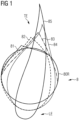
- Figure 1 shows a series of cross-sections through a wind turbine rotor blade 8, commencing with a cross-section 81 through the circular root region 80R and progressing to a cross-section 85 through an airfoil region.
- the shape of the rotor blade transitions in a complex manner from the initially circular shape, as indicated by cross-sections 81 - 84.
- This inboard part of the rotor blade is referred to as the "transition region” or “shoulder region”, and must be dimensioned to withstand high bending moments during normal operation of the wind turbine and also during severe wind conditions.
- the usual approach is to make the rotor blade shell very thick in the transition region, but the added composite material increases the weight of the rotor blade.
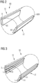
- lightweight carbon-fibre beams 8C can be embedded in the transition region 80 of a rotor blade 8.
- pre-cast carbon-fibre beams 8C made of economical pultruded parts are rectangular in shape and therefore do not conform to the curved leading edge LE or the tapered trailing edge TE.
- the flat shape of such carbon-fibre beams 8C makes it difficult to place them in the composite layers during build-up of the rotor blade shell in the moulding process.
- Figure 3 is a wireframe representation that illustrates a reinforced transition region 30 in an embodiment of the inventive wind turbine rotor blade 3.
- lightweight shape-adaptable pre-cast carbon-fibre beams 1 are embedded in the transition region 30 of the rotor blade 3.
- Each pre-cast adaptable carbon-fibre beam 1 comprises several elongate blocks 1B connected by elongate "hinges" 1H so that the shape of the beam 1 can be adjusted to conform to the shape of the rotor blade shell during the shell moulding procedure.
- FIGs 4 - 6 illustrate stages in the manufacture of such a pre-cast adaptable carbon-fibre beam 1.
- a unidirectional carbon-fibre sheet 11 is laid on a surface.
- Blocks 1B of pultruded carbon-fibre elements 10 are assembled, whereby sheets 12 of biaxial carbon-fibre material are arranged between stack layers.
- Each pultruded carbon-fibre element 10 can have a cross-section with dimensions in the order of 50 mm x 50 mm, and a length in the order of 20 m.
- the elements 10 are selected to form blocks with straight side faces or inclined side faces, as shown here.
- the smallest radius of curvature of the completed adaptable carbon-fibre beam 1 will be determined by the angles ⁇ subtended between the blocks 1B.
- Figure 5 shows a subsequent stage.
- all sheet layers 11, 12 have been pushed downwards in the gaps between adjacent blocks 1B to form a bead or hinge 1H at the underside of the assembly.
- the diagram also shows two lateral tapering elements 1W which will later help the adaptable carbon-fibre beam to be incorporated in the composite layup of a rotor blade.
- the unidirectional carbon-fibre sheet 11 extends outward to one side, to serve as a connecting surface 110 for electrical connection to a rotor blade LPS.
- Figure 6 shows one approach to forming the "hinges" 1H at the junctions between adjacent blocks 1B.
- the moulding surface is a table 2 with sections shaped to form channels 200 that will receive a bundle of sheet material as well as an inflatable hose 20.
- the carbon beam assembly is shown to also include a glass-fibre sheet 13 enclosing the other components.
- the entire assembly can be arranged inside a vacuum bag in preparation for a VARTM procedure, as will be known to the skilled person.
- the moulding surface 2 is also provided with a resin inlet/outlet pair (indicated only schematically) under each elongate block 1B.
- a vacuum pump 24 is used to draw in resin from a reservoir 25 through the resin inlets 22 and to draw out excess resin through the resin outlets 23.
- the diagram shows an enlarged view of a channel 200 between table sections 20, showing the inflatable hose in the centre of the sheet material bundle 11, 12, 13, prior to inflation.
- the hose is inflated, as shown on the right, the sheet layers 11, 12, 13 are pulled taut and pressed together.
- the bead 1H acts as a barrier to the resin, which is inhibited from entering the bead 1H.
- the bead 1H remains “dry” and, after curing, the blocks are freely pivotable about the "hinge” formed by the dry sheet material of the bead 1H along the underside of the cured beam.
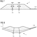
- the pre-cast adaptable carbon-fibre beam 1 is therefore inherently rigid while being shape-adjustable. This is indicated in Figures 7 - 9 , which illustrate shape adaptation of the inventive pre-cast adaptable carbon-fibre beam 1.
- the block structure on either side of a hinge 1H can pivot to some extent, as determined by the angle ⁇ subtended between adjacent blocks.
- Figure 8 shows the smallest radius of curvature when all blocks are pivoted inwards to the greatest extent, allowing the pre-cast adaptable carbon-fibre beam 1 to assume an arcuate shape as indicated by the curved line C.
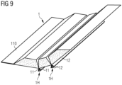
- Figure 9 shows a perspective view of an embodiment of the inventive pre-cast adaptable carbon-fibre beam 1, showing the hinges 1H at the "underside" of the adaptable carbon-fibre beam 1 and blocks which have not (yet) been pivoted to their greatest extent.
- This curved pre-cast adaptable carbon-fibre beam 1 can be arranged in a leading-edge transition region of a rotor blade mould during the layup procedure, so that the cured rotor blade will exhibit given greater structural rigidity without increasing its mass.
- the reduced rotor blade mass and reduced mass moment can facilitate a favourably longer rotor blade length and a corresponding increase in energy production.
- the adaptable carbon-fibre beam 1 is connected to a rotor blade LPS by means of the outwardly extending band 110 of the unidirectional carbon-fibre sheets 11. With this arrangement, it is possible to minimize the risk of flash-over during a lighting strike.
- Figure 10 illustrates a step in the manufacture of a wind turbine rotor blade.
- the diagram shows a lower mould half 3M, at a cross-section through the transition region.
- the diagram shows an embodiment of the inventive pre-cast carbon-fibre beam 1 on the left, near the trailing edge region.
- the pre-cast carbon-fibre beam 1 can adapt to the slight curvature in this region and can easily be embedded in the composite layup 3L of the lower rotor blade half.
- the diagram also shows another embodiment of the inventive pre-cast carbon-fibre beam 1 on the right, near the leading edge region.
- the pre-cast carbon-fibre beam 1 can also easily adapt its shape to be embedded in the composite layup 3L in the rounded shape of the mould in this region.
- This leading-edge pre-cast carbon-fibre beam 1 is shown with a hinge positioned along the junction between the lower mould half 3M and an upper mould half (indicated by the dashed line) The upper portion of the pre-cast carbon-fibre beam 1 can be pivoted upward when the lower layup is complete.
- Figure 11 shows an alternative manner of forming the pre-cast carbon beam 1.
- the assembly is prepared as described above in Figure 4 and Figure 5 and comprises stacks of pultruded carbon elements and glass-fibre sheets 11, 12.
- a thin rod 4 is used to bring the excess sheet material below the level of the moulding surface 2 and, during the resin infusion step, tension is maintained as indicated by the arrows so that the sheet layers are pressed together to inhibit resin flow from the blocks 1B into the beads 1H.
- the bead 1H can be formed by clamping the sheet layers firmly together along their entire length. The only requirement at this stage is that the sheet layers 11, 12 are pressed against each other in such a way as to prevent liquid resin from passing from a block 1B into the bead 1H.
Landscapes
- Engineering & Computer Science (AREA)
- Mechanical Engineering (AREA)
- Chemical & Material Sciences (AREA)
- Composite Materials (AREA)
- Life Sciences & Earth Sciences (AREA)
- Sustainable Development (AREA)
- Sustainable Energy (AREA)
- Combustion & Propulsion (AREA)
- General Engineering & Computer Science (AREA)
- Wind Motors (AREA)
- Moulding By Coating Moulds (AREA)
Claims (15)
- Procédé de fabrication d'un faisceau de fibres de carbone infusé de résine, adaptable, pré-coulé (1), lequel procédé comprend les étapes consistant à- agencer une pluralité de blocs (1B) de fibres de carbone allongés côte-à-côte, dans lequel un bloc (1B) de fibres de carbone comprend de nombreux éléments de fibres de carbone (10) pultrudés ;- agencer des feuilles (11, 12, 13) pour enfermer les blocs (1B) et pour s'étendre sur des faces opposées de blocs (1B) adjacents ;- agencer les feuilles (11, 12, 13) pour qu'elles convergent sous la forme d'un cordon allongé (1H) se projetant vers l'extérieur au niveau d'une jonction entre des blocs (1B) adjacents ; et- tirer le cordon allongé (1H) pour empêcher l'écoulement de la résine entre les blocs (1B) durant une étape d'infusion de résine.
- Procédé selon la revendication 1, comprenant une étape préparatoire d'assemblage des blocs (1B) de fibres de carbone par l'empilement de couches de bandes de fibres de carbone (10) allongées.
- Procédé selon l'une quelconque des revendications précédentes, comprenant une étape d'agencement de feuilles de fibres de carbone biaxiales (12) entre des couches de pile (10) successives.
- Procédé selon l'une quelconque des revendications précédentes, comprenant une étape d'insertion d'un tuyau (21) gonflable dans l'intérieur du cordon (1H), et dans lequel l'étape de traction sur le cordon allongé (1H) est atteinte par le gonflage du tuyau (21).
- Procédé selon l'une quelconque des revendications précédentes, comprenant une étape de fourniture d'un moule (2) ayant une cavité (200) pour un cordon (1H), laquelle cavité (200) est mise en forme pour recevoir les feuilles (11, 12, 13) et un tuyau (21) gonflable.
- Faisceau de fibres de carbone adaptable pré-coulé (1) fabriqué en utilisant le procédé selon l'une quelconque des revendications 1 à 5, comprenant une pluralité de blocs (1B) de fibres de carbone infusés de résine, dans lequel au moins une paire de blocs (1B) adjacents sont joints par un cordon allongé (1H) et peuvent pivoter autour du cordon allongé (1H).
- Faisceau de fibres de carbone adaptable pré-coulé selon la revendication précédente, comprenant une feuille de fibres de carbone unidirectionnelle (11) agencée pour enfermer les blocs (1B) de fibres de carbone.
- Faisceau de fibres de carbone adaptable pré-coulé selon l'une quelconque des revendications précédentes 6 et 7, comprenant une feuille de couverture en fibres de verre (13) agencée autour de la feuille de fibres de carbone unidirectionnelle (11).
- Faisceau de fibres de carbone adaptable pré-coulé selon l'une quelconque des revendications précédentes 6 à 8, dans lequel chaque bloc (1B) comprend une pile d'au moins deux fibres de carbone (10) pultrudées, plus préférablement au moins trois fibres de carbone (10) pultrudées.
- Faisceau de fibres de carbone adaptable pré-coulé selon l'une quelconque des revendications précédentes 6 à 9, dans lequel des faces opposées de blocs (1B) adjacents sous-tendent un angle (α) situé dans la plage de 5° à 20°.
- Faisceau de fibres de carbone adaptable selon l'une quelconque des revendications précédentes 6 à 10, comprenant un élément en forme de coin (1W) agencé le long d'une face extérieure d'un bloc (1B).
- Procédé de fabrication d'une pale de rotor (3) d'éolienne, lequel procédé comprend les étapes consistant à- fournir un moule de pale de rotor (3M) pour recevoir une superposition de composites (3L) ;- fournir un faisceau de fibres de carbone adaptable pré-coulé (1) selon l'une quelconque des revendications 6 à 11 ;- incorporer le faisceau de fibres de carbone pré-coulé (1) dans la superposition de composites (3L) et ajuster la forme du faisceau de fibres de carbone pré-coulé (1) en fonction de la forme du moule de pale de rotor (3M).
- Pale de rotor (3) fabriquée en utilisant le procédé selon la revendication 12, comprenant de nombreux faisceaux de fibres de carbone adaptables pré-coulés (1) dans une région de transition (30) de la pale de rotor (3).
- Pale de rotor selon la revendication 13, incorporant un faisceau de fibres de carbone adaptable pré-coulé (1) au niveau du bord d'attaque (LE) de la région de transition (30).
- Pale de rotor selon la revendication 13 ou la revendication 14, incorporant un faisceau de fibres de carbone adaptable pré-coulé (1) au niveau du bord de fuite (TE) de la région de transition (30).
Priority Applications (7)
| Application Number | Priority Date | Filing Date | Title |
|---|---|---|---|
| PL20216420.8T PL4019233T3 (pl) | 2020-12-22 | 2020-12-22 | Sposób wytwarzania możliwej do przystosowania belki z włókna węglowego |
| EP20216420.8A EP4019233B1 (fr) | 2020-12-22 | 2020-12-22 | Procédé de fabrication d'un faisceau de fibres de carbone adaptable |
| DK20216420.8T DK4019233T3 (en) | 2020-12-22 | 2020-12-22 | Method of manufacturing an adaptable carbon-fibre beam |
| US17/537,597 US12180925B2 (en) | 2020-12-22 | 2021-11-30 | Method of manufacturing an adaptable carbon-fiber beam |
| TW110147886A TWI804121B (zh) | 2020-12-22 | 2021-12-21 | 適應性預鑄碳纖維樑及製造適應性預鑄碳纖維樑的方法以及風力渦輪機轉子葉片及製造風力渦輪機轉子葉片的方法 |
| CN202111579134.XA CN114714644B (zh) | 2020-12-22 | 2021-12-22 | 制造可适应碳纤维梁的方法 |
| US18/932,424 US20250052226A1 (en) | 2020-12-22 | 2024-10-30 | Method of manufacturing an adaptable carbon-fiber beam |
Applications Claiming Priority (1)
| Application Number | Priority Date | Filing Date | Title |
|---|---|---|---|
| EP20216420.8A EP4019233B1 (fr) | 2020-12-22 | 2020-12-22 | Procédé de fabrication d'un faisceau de fibres de carbone adaptable |
Publications (2)
| Publication Number | Publication Date |
|---|---|
| EP4019233A1 EP4019233A1 (fr) | 2022-06-29 |
| EP4019233B1 true EP4019233B1 (fr) | 2025-03-12 |
Family
ID=73856770
Family Applications (1)
| Application Number | Title | Priority Date | Filing Date |
|---|---|---|---|
| EP20216420.8A Active EP4019233B1 (fr) | 2020-12-22 | 2020-12-22 | Procédé de fabrication d'un faisceau de fibres de carbone adaptable |
Country Status (6)
| Country | Link |
|---|---|
| US (2) | US12180925B2 (fr) |
| EP (1) | EP4019233B1 (fr) |
| CN (1) | CN114714644B (fr) |
| DK (1) | DK4019233T3 (fr) |
| PL (1) | PL4019233T3 (fr) |
| TW (1) | TWI804121B (fr) |
Family Cites Families (26)
| Publication number | Priority date | Publication date | Assignee | Title |
|---|---|---|---|---|
| US3765841A (en) | 1971-08-06 | 1973-10-16 | Beckman Instruments Inc | Method and apparatus for chemical analysis |
| DE2236479A1 (de) * | 1972-07-25 | 1974-02-07 | Erich Sennebogen | Schichtverbundelement und verfahren zu dessen herstellung |
| US5232762A (en) * | 1990-02-05 | 1993-08-03 | Ruby Victor L | Product of a two phase, self configuring coreless structural element for furniture and the like |
| CN101137841B (zh) | 2005-02-03 | 2013-01-09 | 维斯塔斯风力系统有限公司 | 制造风轮机叶片壳体构件的方法 |
| TW201022023A (en) * | 2008-12-05 | 2010-06-16 | Chung Shan Inst Of Science | Manufacturing method of composite with core of resin channels |
| CN105082634A (zh) * | 2009-10-01 | 2015-11-25 | 美利肯公司 | 复合芯和板 |
| MX341495B (es) * | 2010-01-14 | 2016-08-23 | Neptco Inc * | Componentes de pala de rotor de turbina eolica y metodos para la fabricacion de los mismos. |
| CN102975374B (zh) | 2012-09-29 | 2015-09-23 | 航天材料及工艺研究所 | 风机叶片用碳纤维复合材料主梁帽的制造方法及制造装置 |
| DE102013205779A1 (de) * | 2013-04-02 | 2014-10-02 | Deutsches Zentrum für Luft- und Raumfahrt e.V. | Verfahren zur Herstellung eines Formbauteils |
| WO2014166493A1 (fr) * | 2013-04-08 | 2014-10-16 | Vestas Wind Systems A/S | Préforme de fibre pour pose sur une surface incurvée d'un moule |
| US10428790B2 (en) | 2013-12-23 | 2019-10-01 | Vestas Wind Systems A/S | Wind turbine blades |
| US10179439B2 (en) | 2014-01-31 | 2019-01-15 | Lm Wp Patent Holding A/S | Wind turbine blade part manufactured in two steps |
| GB201407671D0 (en) | 2014-05-01 | 2014-06-18 | Lm Wp Patent Holding As | A wind turbine blade and an associated manufacturing method |
| US20160146185A1 (en) * | 2014-11-25 | 2016-05-26 | General Electric Company | Methods for manufacturing a spar cap for a wind turbine rotor blade |
| US10077758B2 (en) * | 2015-06-30 | 2018-09-18 | General Electric Company | Corrugated pre-cured laminate plates for use within wind turbine rotor blades |
| US10113532B2 (en) * | 2015-10-23 | 2018-10-30 | General Electric Company | Pre-cured composites for rotor blade components |
| EP3393767B1 (fr) * | 2015-12-23 | 2024-02-14 | LM Wind Power A/S | Procédé de fabrication d'une structure composite stratifiée d'une partie de pale de turbine éolienne et ladite partie |
| US11752709B2 (en) | 2016-11-17 | 2023-09-12 | Vestas Wind Systems A/S | Reinforcing structure for a wind turbine blade |
| DE102017113769A1 (de) * | 2017-06-21 | 2018-12-27 | Nordex Energy Gmbh | Pultrudiertes Profil mit Abreißgewebe |
| CN107718621B (zh) | 2017-09-29 | 2019-11-19 | 上海玻璃钢研究院东台有限公司 | 一种高强度捻合型风电叶片及其制备方法 |
| CN108005846B (zh) * | 2017-11-28 | 2019-11-12 | 中国人民解放军国防科技大学 | 大型风电叶片用主承力梁、混杂翼梁复合材料风电叶片及其制备方法 |
| CN108312575A (zh) * | 2018-04-17 | 2018-07-24 | 连云港中复连众复合材料集团有限公司 | 一种使用碳纤维拉挤型材与玻璃纤维织物混合制造风电叶片主梁、辅梁的方法 |
| EP3569394A1 (fr) | 2018-05-17 | 2019-11-20 | Siemens Gamesa Renewable Energy A/S | Procédé de fabrication d'un capuchon de longeron |
| EP3599374B1 (fr) * | 2018-07-23 | 2024-01-03 | Siemens Gamesa Renewable Energy A/S | Pale d'éolienne comprenant un matériau composite et procédé de production d'une pale d'éolienne |
| ES2926353T3 (es) * | 2019-04-03 | 2022-10-25 | Siemens Gamesa Renewable Energy As | Cordón de larguero para una pala de turbina eólica de una turbina eólica, pala de turbina eólica, turbina eólica y método para fabricar un cordón de larguero para una pala de turbina eólica de una turbina eólica |
| KR102267510B1 (ko) | 2019-12-03 | 2021-06-18 | 엘지전자 주식회사 | 진공 청소기 |
-
2020
- 2020-12-22 EP EP20216420.8A patent/EP4019233B1/fr active Active
- 2020-12-22 DK DK20216420.8T patent/DK4019233T3/da active
- 2020-12-22 PL PL20216420.8T patent/PL4019233T3/pl unknown
-
2021
- 2021-11-30 US US17/537,597 patent/US12180925B2/en active Active
- 2021-12-21 TW TW110147886A patent/TWI804121B/zh active
- 2021-12-22 CN CN202111579134.XA patent/CN114714644B/zh active Active
-
2024
- 2024-10-30 US US18/932,424 patent/US20250052226A1/en active Pending
Also Published As
| Publication number | Publication date |
|---|---|
| PL4019233T3 (pl) | 2025-06-02 |
| CN114714644A (zh) | 2022-07-08 |
| EP4019233A1 (fr) | 2022-06-29 |
| US12180925B2 (en) | 2024-12-31 |
| CN114714644B (zh) | 2024-09-20 |
| DK4019233T3 (en) | 2025-04-28 |
| US20250052226A1 (en) | 2025-02-13 |
| TWI804121B (zh) | 2023-06-01 |
| TW202231452A (zh) | 2022-08-16 |
| US20220195983A1 (en) | 2022-06-23 |
Similar Documents
| Publication | Publication Date | Title |
|---|---|---|
| US11752709B2 (en) | Reinforcing structure for a wind turbine blade | |
| JP6105619B2 (ja) | 風力タービンブレード | |
| US11041477B2 (en) | Reinforcing structure for a wind turbine blade | |
| US4339230A (en) | Bifoil blade | |
| US10077758B2 (en) | Corrugated pre-cured laminate plates for use within wind turbine rotor blades | |
| EP3393767B1 (fr) | Procédé de fabrication d'une structure composite stratifiée d'une partie de pale de turbine éolienne et ladite partie | |
| CN111433012A (zh) | 制造用于模制风力涡轮机叶片的至少两个预制件的方法 | |
| CN113165296B (zh) | 关于风力涡轮机叶片制造的改进 | |
| CN111794901A (zh) | 用于风力涡轮机的叶片的翼梁帽、风力涡轮机叶片、风力涡轮机以及制造翼梁帽的方法 | |
| CN114930015A (zh) | 风力涡轮机转子叶片的等电位联结 | |
| EP4212324B1 (fr) | Fabrication d'un capuchon de longeron de pale d'éolienne | |
| CN106574602B (zh) | 加强的风力涡轮机叶片部件 | |
| EP4019233B1 (fr) | Procédé de fabrication d'un faisceau de fibres de carbone adaptable | |
| US12540597B2 (en) | Spar cap with tapering and serrated end section | |
| US20240018938A1 (en) | Wind turbine blade having buckling-resistant spar caps | |
| EP3946909B1 (fr) | Fabrication d'une partie de coque renforcée d'une pale d'éolienne | |
| US20230166472A1 (en) | Method for manufacturing a wind turbine blade and wind turbine blade obtained thereby | |
| US20240399678A1 (en) | Spar cap for a wind turbine blade | |
| WO2023274481A1 (fr) | Pale d'éolienne |
Legal Events
| Date | Code | Title | Description |
|---|---|---|---|
| PUAI | Public reference made under article 153(3) epc to a published international application that has entered the european phase |
Free format text: ORIGINAL CODE: 0009012 |
|
| STAA | Information on the status of an ep patent application or granted ep patent |
Free format text: STATUS: THE APPLICATION HAS BEEN PUBLISHED |
|
| AK | Designated contracting states |
Kind code of ref document: A1 Designated state(s): AL AT BE BG CH CY CZ DE DK EE ES FI FR GB GR HR HU IE IS IT LI LT LU LV MC MK MT NL NO PL PT RO RS SE SI SK SM TR |
|
| STAA | Information on the status of an ep patent application or granted ep patent |
Free format text: STATUS: REQUEST FOR EXAMINATION WAS MADE |
|
| 17P | Request for examination filed |
Effective date: 20230102 |
|
| RBV | Designated contracting states (corrected) |
Designated state(s): AL AT BE BG CH CY CZ DE DK EE ES FI FR GB GR HR HU IE IS IT LI LT LU LV MC MK MT NL NO PL PT RO RS SE SI SK SM TR |
|
| GRAP | Despatch of communication of intention to grant a patent |
Free format text: ORIGINAL CODE: EPIDOSNIGR1 |
|
| STAA | Information on the status of an ep patent application or granted ep patent |
Free format text: STATUS: GRANT OF PATENT IS INTENDED |
|
| RIC1 | Information provided on ipc code assigned before grant |
Ipc: B29L 31/08 20060101ALN20240917BHEP Ipc: B29C 37/00 20060101ALI20240917BHEP Ipc: B29C 70/56 20060101ALI20240917BHEP Ipc: B29C 70/54 20060101ALI20240917BHEP Ipc: F03D 1/06 20060101ALI20240917BHEP Ipc: B29D 99/00 20100101ALI20240917BHEP Ipc: B29C 70/84 20060101ALI20240917BHEP Ipc: B29C 70/68 20060101ALI20240917BHEP Ipc: B29C 70/48 20060101ALI20240917BHEP Ipc: B29C 70/30 20060101AFI20240917BHEP |
|
| RIC1 | Information provided on ipc code assigned before grant |
Ipc: B29L 31/08 20060101ALN20240920BHEP Ipc: B29C 37/00 20060101ALI20240920BHEP Ipc: B29C 70/56 20060101ALI20240920BHEP Ipc: B29C 70/54 20060101ALI20240920BHEP Ipc: F03D 1/06 20060101ALI20240920BHEP Ipc: B29D 99/00 20100101ALI20240920BHEP Ipc: B29C 70/84 20060101ALI20240920BHEP Ipc: B29C 70/68 20060101ALI20240920BHEP Ipc: B29C 70/48 20060101ALI20240920BHEP Ipc: B29C 70/30 20060101AFI20240920BHEP |
|
| INTG | Intention to grant announced |
Effective date: 20241009 |
|
| GRAS | Grant fee paid |
Free format text: ORIGINAL CODE: EPIDOSNIGR3 |
|
| GRAA | (expected) grant |
Free format text: ORIGINAL CODE: 0009210 |
|
| STAA | Information on the status of an ep patent application or granted ep patent |
Free format text: STATUS: THE PATENT HAS BEEN GRANTED |
|
| AK | Designated contracting states |
Kind code of ref document: B1 Designated state(s): AL AT BE BG CH CY CZ DE DK EE ES FI FR GB GR HR HU IE IS IT LI LT LU LV MC MK MT NL NO PL PT RO RS SE SI SK SM TR |
|
| REG | Reference to a national code |
Ref country code: GB Ref legal event code: FG4D |
|
| REG | Reference to a national code |
Ref country code: CH Ref legal event code: EP |
|
| REG | Reference to a national code |
Ref country code: DE Ref legal event code: R096 Ref document number: 602020047536 Country of ref document: DE |
|
| REG | Reference to a national code |
Ref country code: IE Ref legal event code: FG4D |
|
| REG | Reference to a national code |
Ref country code: DK Ref legal event code: T3 Effective date: 20250425 |
|
| REG | Reference to a national code |
Ref country code: NL Ref legal event code: FP |
|
| PG25 | Lapsed in a contracting state [announced via postgrant information from national office to epo] |
Ref country code: RS Free format text: LAPSE BECAUSE OF FAILURE TO SUBMIT A TRANSLATION OF THE DESCRIPTION OR TO PAY THE FEE WITHIN THE PRESCRIBED TIME-LIMIT Effective date: 20250612 |
|
| PG25 | Lapsed in a contracting state [announced via postgrant information from national office to epo] |
Ref country code: FI Free format text: LAPSE BECAUSE OF FAILURE TO SUBMIT A TRANSLATION OF THE DESCRIPTION OR TO PAY THE FEE WITHIN THE PRESCRIBED TIME-LIMIT Effective date: 20250312 |
|
| PG25 | Lapsed in a contracting state [announced via postgrant information from national office to epo] |
Ref country code: ES Free format text: LAPSE BECAUSE OF FAILURE TO SUBMIT A TRANSLATION OF THE DESCRIPTION OR TO PAY THE FEE WITHIN THE PRESCRIBED TIME-LIMIT Effective date: 20250312 |
|
| REG | Reference to a national code |
Ref country code: LT Ref legal event code: MG9D |
|
| PG25 | Lapsed in a contracting state [announced via postgrant information from national office to epo] |
Ref country code: NO Free format text: LAPSE BECAUSE OF FAILURE TO SUBMIT A TRANSLATION OF THE DESCRIPTION OR TO PAY THE FEE WITHIN THE PRESCRIBED TIME-LIMIT Effective date: 20250612 |
|
| PG25 | Lapsed in a contracting state [announced via postgrant information from national office to epo] |
Ref country code: HR Free format text: LAPSE BECAUSE OF FAILURE TO SUBMIT A TRANSLATION OF THE DESCRIPTION OR TO PAY THE FEE WITHIN THE PRESCRIBED TIME-LIMIT Effective date: 20250312 |
|
| PG25 | Lapsed in a contracting state [announced via postgrant information from national office to epo] |
Ref country code: LV Free format text: LAPSE BECAUSE OF FAILURE TO SUBMIT A TRANSLATION OF THE DESCRIPTION OR TO PAY THE FEE WITHIN THE PRESCRIBED TIME-LIMIT Effective date: 20250312 |
|
| PG25 | Lapsed in a contracting state [announced via postgrant information from national office to epo] |
Ref country code: GR Free format text: LAPSE BECAUSE OF FAILURE TO SUBMIT A TRANSLATION OF THE DESCRIPTION OR TO PAY THE FEE WITHIN THE PRESCRIBED TIME-LIMIT Effective date: 20250613 Ref country code: BG Free format text: LAPSE BECAUSE OF FAILURE TO SUBMIT A TRANSLATION OF THE DESCRIPTION OR TO PAY THE FEE WITHIN THE PRESCRIBED TIME-LIMIT Effective date: 20250312 |
|
| REG | Reference to a national code |
Ref country code: AT Ref legal event code: MK05 Ref document number: 1774680 Country of ref document: AT Kind code of ref document: T Effective date: 20250312 |
|
| PG25 | Lapsed in a contracting state [announced via postgrant information from national office to epo] |
Ref country code: SE Free format text: LAPSE BECAUSE OF FAILURE TO SUBMIT A TRANSLATION OF THE DESCRIPTION OR TO PAY THE FEE WITHIN THE PRESCRIBED TIME-LIMIT Effective date: 20250312 |
|
| PG25 | Lapsed in a contracting state [announced via postgrant information from national office to epo] |
Ref country code: SM Free format text: LAPSE BECAUSE OF FAILURE TO SUBMIT A TRANSLATION OF THE DESCRIPTION OR TO PAY THE FEE WITHIN THE PRESCRIBED TIME-LIMIT Effective date: 20250312 |
|
| PG25 | Lapsed in a contracting state [announced via postgrant information from national office to epo] |
Ref country code: PT Free format text: LAPSE BECAUSE OF FAILURE TO SUBMIT A TRANSLATION OF THE DESCRIPTION OR TO PAY THE FEE WITHIN THE PRESCRIBED TIME-LIMIT Effective date: 20250714 |
|
| PGFP | Annual fee paid to national office [announced via postgrant information from national office to epo] |
Ref country code: DK Payment date: 20250912 Year of fee payment: 6 |
|
| PG25 | Lapsed in a contracting state [announced via postgrant information from national office to epo] |
Ref country code: IT Free format text: LAPSE BECAUSE OF FAILURE TO SUBMIT A TRANSLATION OF THE DESCRIPTION OR TO PAY THE FEE WITHIN THE PRESCRIBED TIME-LIMIT Effective date: 20250312 |
|
| PG25 | Lapsed in a contracting state [announced via postgrant information from national office to epo] |
Ref country code: AT Free format text: LAPSE BECAUSE OF FAILURE TO SUBMIT A TRANSLATION OF THE DESCRIPTION OR TO PAY THE FEE WITHIN THE PRESCRIBED TIME-LIMIT Effective date: 20250312 |
|
| PG25 | Lapsed in a contracting state [announced via postgrant information from national office to epo] |
Ref country code: EE Free format text: LAPSE BECAUSE OF FAILURE TO SUBMIT A TRANSLATION OF THE DESCRIPTION OR TO PAY THE FEE WITHIN THE PRESCRIBED TIME-LIMIT Effective date: 20250312 Ref country code: CZ Free format text: LAPSE BECAUSE OF FAILURE TO SUBMIT A TRANSLATION OF THE DESCRIPTION OR TO PAY THE FEE WITHIN THE PRESCRIBED TIME-LIMIT Effective date: 20250312 |
|
| PG25 | Lapsed in a contracting state [announced via postgrant information from national office to epo] |
Ref country code: RO Free format text: LAPSE BECAUSE OF FAILURE TO SUBMIT A TRANSLATION OF THE DESCRIPTION OR TO PAY THE FEE WITHIN THE PRESCRIBED TIME-LIMIT Effective date: 20250312 |
|
| PG25 | Lapsed in a contracting state [announced via postgrant information from national office to epo] |
Ref country code: SK Free format text: LAPSE BECAUSE OF FAILURE TO SUBMIT A TRANSLATION OF THE DESCRIPTION OR TO PAY THE FEE WITHIN THE PRESCRIBED TIME-LIMIT Effective date: 20250312 |
|
| PG25 | Lapsed in a contracting state [announced via postgrant information from national office to epo] |
Ref country code: IS Free format text: LAPSE BECAUSE OF FAILURE TO SUBMIT A TRANSLATION OF THE DESCRIPTION OR TO PAY THE FEE WITHIN THE PRESCRIBED TIME-LIMIT Effective date: 20250712 |
|
| REG | Reference to a national code |
Ref country code: DE Ref legal event code: R097 Ref document number: 602020047536 Country of ref document: DE |
|
| PGFP | Annual fee paid to national office [announced via postgrant information from national office to epo] |
Ref country code: DE Payment date: 20250829 Year of fee payment: 6 |
|
| PGFP | Annual fee paid to national office [announced via postgrant information from national office to epo] |
Ref country code: GB Payment date: 20251223 Year of fee payment: 6 |
|
| PGFP | Annual fee paid to national office [announced via postgrant information from national office to epo] |
Ref country code: NL Payment date: 20251222 Year of fee payment: 6 Ref country code: FR Payment date: 20251223 Year of fee payment: 6 |
|
| PLBE | No opposition filed within time limit |
Free format text: ORIGINAL CODE: 0009261 |
|
| STAA | Information on the status of an ep patent application or granted ep patent |
Free format text: STATUS: NO OPPOSITION FILED WITHIN TIME LIMIT |
|
| REG | Reference to a national code |
Ref country code: CH Ref legal event code: L10 Free format text: ST27 STATUS EVENT CODE: U-0-0-L10-L00 (AS PROVIDED BY THE NATIONAL OFFICE) Effective date: 20260121 |
|
| PGFP | Annual fee paid to national office [announced via postgrant information from national office to epo] |
Ref country code: PL Payment date: 20251128 Year of fee payment: 6 |
|
| 26N | No opposition filed |
Effective date: 20251215 |