EP4019302B1 - Fahrzeug, steuerungsverfahren für fahrzeugaufhängung und zugehörige steuervorrichtung - Google Patents
Fahrzeug, steuerungsverfahren für fahrzeugaufhängung und zugehörige steuervorrichtung Download PDFInfo
- Publication number
- EP4019302B1 EP4019302B1 EP21214344.0A EP21214344A EP4019302B1 EP 4019302 B1 EP4019302 B1 EP 4019302B1 EP 21214344 A EP21214344 A EP 21214344A EP 4019302 B1 EP4019302 B1 EP 4019302B1
- Authority
- EP
- European Patent Office
- Prior art keywords
- component
- vehicle
- variable damper
- force
- speed
- Prior art date
- Legal status (The legal status is an assumption and is not a legal conclusion. Google has not performed a legal analysis and makes no representation as to the accuracy of the status listed.)
- Active
Links
Images



Classifications
-
- B—PERFORMING OPERATIONS; TRANSPORTING
- B60—VEHICLES IN GENERAL
- B60G—VEHICLE SUSPENSION ARRANGEMENTS
- B60G17/00—Resilient suspensions having means for adjusting the spring or vibration-damper characteristics, for regulating the distance between a supporting surface and a sprung part of vehicle or for locking suspension during use to meet varying vehicular or surface conditions, e.g. due to speed or load
- B60G17/015—Resilient suspensions having means for adjusting the spring or vibration-damper characteristics, for regulating the distance between a supporting surface and a sprung part of vehicle or for locking suspension during use to meet varying vehicular or surface conditions, e.g. due to speed or load the regulating means comprising electric or electronic elements
- B60G17/0152—Resilient suspensions having means for adjusting the spring or vibration-damper characteristics, for regulating the distance between a supporting surface and a sprung part of vehicle or for locking suspension during use to meet varying vehicular or surface conditions, e.g. due to speed or load the regulating means comprising electric or electronic elements characterised by the action on a particular type of suspension unit
-
- B—PERFORMING OPERATIONS; TRANSPORTING
- B60—VEHICLES IN GENERAL
- B60G—VEHICLE SUSPENSION ARRANGEMENTS
- B60G17/00—Resilient suspensions having means for adjusting the spring or vibration-damper characteristics, for regulating the distance between a supporting surface and a sprung part of vehicle or for locking suspension during use to meet varying vehicular or surface conditions, e.g. due to speed or load
- B60G17/015—Resilient suspensions having means for adjusting the spring or vibration-damper characteristics, for regulating the distance between a supporting surface and a sprung part of vehicle or for locking suspension during use to meet varying vehicular or surface conditions, e.g. due to speed or load the regulating means comprising electric or electronic elements
- B60G17/016—Resilient suspensions having means for adjusting the spring or vibration-damper characteristics, for regulating the distance between a supporting surface and a sprung part of vehicle or for locking suspension during use to meet varying vehicular or surface conditions, e.g. due to speed or load the regulating means comprising electric or electronic elements characterised by their responsiveness, when the vehicle is travelling, to specific motion, a specific condition, or driver input
-
- B—PERFORMING OPERATIONS; TRANSPORTING
- B60—VEHICLES IN GENERAL
- B60G—VEHICLE SUSPENSION ARRANGEMENTS
- B60G17/00—Resilient suspensions having means for adjusting the spring or vibration-damper characteristics, for regulating the distance between a supporting surface and a sprung part of vehicle or for locking suspension during use to meet varying vehicular or surface conditions, e.g. due to speed or load
- B60G17/015—Resilient suspensions having means for adjusting the spring or vibration-damper characteristics, for regulating the distance between a supporting surface and a sprung part of vehicle or for locking suspension during use to meet varying vehicular or surface conditions, e.g. due to speed or load the regulating means comprising electric or electronic elements
- B60G17/018—Resilient suspensions having means for adjusting the spring or vibration-damper characteristics, for regulating the distance between a supporting surface and a sprung part of vehicle or for locking suspension during use to meet varying vehicular or surface conditions, e.g. due to speed or load the regulating means comprising electric or electronic elements characterised by the use of a specific signal treatment or control method
-
- B—PERFORMING OPERATIONS; TRANSPORTING
- B60—VEHICLES IN GENERAL
- B60G—VEHICLE SUSPENSION ARRANGEMENTS
- B60G17/00—Resilient suspensions having means for adjusting the spring or vibration-damper characteristics, for regulating the distance between a supporting surface and a sprung part of vehicle or for locking suspension during use to meet varying vehicular or surface conditions, e.g. due to speed or load
- B60G17/015—Resilient suspensions having means for adjusting the spring or vibration-damper characteristics, for regulating the distance between a supporting surface and a sprung part of vehicle or for locking suspension during use to meet varying vehicular or surface conditions, e.g. due to speed or load the regulating means comprising electric or electronic elements
- B60G17/019—Resilient suspensions having means for adjusting the spring or vibration-damper characteristics, for regulating the distance between a supporting surface and a sprung part of vehicle or for locking suspension during use to meet varying vehicular or surface conditions, e.g. due to speed or load the regulating means comprising electric or electronic elements characterised by the type of sensor or the arrangement thereof
- B60G17/01908—Acceleration or inclination sensors
-
- B—PERFORMING OPERATIONS; TRANSPORTING
- B60—VEHICLES IN GENERAL
- B60G—VEHICLE SUSPENSION ARRANGEMENTS
- B60G17/00—Resilient suspensions having means for adjusting the spring or vibration-damper characteristics, for regulating the distance between a supporting surface and a sprung part of vehicle or for locking suspension during use to meet varying vehicular or surface conditions, e.g. due to speed or load
- B60G17/06—Characteristics of dampers, e.g. mechanical dampers
- B60G17/08—Characteristics of fluid dampers
-
- B—PERFORMING OPERATIONS; TRANSPORTING
- B60—VEHICLES IN GENERAL
- B60G—VEHICLE SUSPENSION ARRANGEMENTS
- B60G2400/00—Indexing codes relating to detected, measured or calculated conditions or factors
- B60G2400/10—Acceleration; Deceleration
- B60G2400/102—Acceleration; Deceleration vertical
-
- B—PERFORMING OPERATIONS; TRANSPORTING
- B60—VEHICLES IN GENERAL
- B60G—VEHICLE SUSPENSION ARRANGEMENTS
- B60G2400/00—Indexing codes relating to detected, measured or calculated conditions or factors
- B60G2400/20—Speed
- B60G2400/206—Body oscillation speed; Body vibration frequency
-
- B—PERFORMING OPERATIONS; TRANSPORTING
- B60—VEHICLES IN GENERAL
- B60G—VEHICLE SUSPENSION ARRANGEMENTS
- B60G2400/00—Indexing codes relating to detected, measured or calculated conditions or factors
- B60G2400/25—Stroke; Height; Displacement
- B60G2400/252—Stroke; Height; Displacement vertical
-
- B—PERFORMING OPERATIONS; TRANSPORTING
- B60—VEHICLES IN GENERAL
- B60G—VEHICLE SUSPENSION ARRANGEMENTS
- B60G2500/00—Indexing codes relating to the regulated action or device
- B60G2500/10—Damping action or damper
-
- B—PERFORMING OPERATIONS; TRANSPORTING
- B60—VEHICLES IN GENERAL
- B60G—VEHICLE SUSPENSION ARRANGEMENTS
- B60G2600/00—Indexing codes relating to particular elements, systems or processes used on suspension systems or suspension control systems
- B60G2600/17—Proportional control, i.e. gain control
- B60G2600/172—Weighting coefficients or factors
-
- B—PERFORMING OPERATIONS; TRANSPORTING
- B60—VEHICLES IN GENERAL
- B60G—VEHICLE SUSPENSION ARRANGEMENTS
- B60G2600/00—Indexing codes relating to particular elements, systems or processes used on suspension systems or suspension control systems
- B60G2600/18—Automatic control means
- B60G2600/184—Semi-Active control means
-
- B—PERFORMING OPERATIONS; TRANSPORTING
- B60—VEHICLES IN GENERAL
- B60G—VEHICLE SUSPENSION ARRANGEMENTS
- B60G2600/00—Indexing codes relating to particular elements, systems or processes used on suspension systems or suspension control systems
- B60G2600/82—Indexing codes relating to particular elements, systems or processes used on suspension systems or suspension control systems duty rate function
-
- B—PERFORMING OPERATIONS; TRANSPORTING
- B60—VEHICLES IN GENERAL
- B60G—VEHICLE SUSPENSION ARRANGEMENTS
- B60G2800/00—Indexing codes relating to the type of movement or to the condition of the vehicle and to the end result to be achieved by the control action
- B60G2800/16—Running
- B60G2800/162—Reducing road induced vibrations
-
- B—PERFORMING OPERATIONS; TRANSPORTING
- B60—VEHICLES IN GENERAL
- B60G—VEHICLE SUSPENSION ARRANGEMENTS
- B60G2800/00—Indexing codes relating to the type of movement or to the condition of the vehicle and to the end result to be achieved by the control action
- B60G2800/90—System Controller type
- B60G2800/91—Suspension Control
- B60G2800/916—Body Vibration Control
Definitions
- This disclosure generally relates to the field of vehicle technologies, and the invention, in particular, relates to a vehicle, a control method for a vehicle suspension, and a related control device.
- a vehicle suspension is disposed in the vehicle.
- the vehicle suspension is an apparatus located between a frame and a wheel.
- the vehicle suspension includes a plurality of components such as an elastic element and a variable damping shock absorber (namely, a variable damper).
- a variable damper For a specific structural diagram of the vehicle suspension, refer to FIG. 2 .
- the variable damper is disposed around the elastic element.
- the elastic element and the variable damper connect the frame to the wheel.
- the elastic element may reduce the impact, or the variable damper may provide a reverse force to the frame to reduce vibration caused by the impact.
- the elastic element functions together with the variable damper to ensure smooth driving of the vehicle.
- Rigidity of the elastic element is usually fixed.
- a force that needs to be provided by the variable damper in the vehicle suspension to the frame should vary with an actual road condition. How to adjust the force that is to be provided by the variable damper to the frame to reduce vehicle vibration is one of currently studied problems.
- a two-state skyhook control method is usually used to adjust a damping force of a variable damper.
- One of two damping factors of the variable damper is selected based on a relative motion trend of both ends of a vehicle suspension and a motion speed of a frame.
- the damping force of the variable damper is related to a damping factor of the variable damper, and different damping factors correspond to different damping forces.
- the damping force of the variable damper is adjusted by selecting the damping factor of the variable damper. A damping force obtained through adjustment of this control policy is not accurate enough.
- US 2006/224286 A1 relates a control system for an adjustable damping force damper.
- the control system includes a damper and a spring provided on a suspension apparatus of a vehicle and a sprung speed sensor for detecting a speed of an upper member of the spring.
- the sprung speed is generated when the vehicle runs over steps on a road surface.
- a control unit is used for setting a gain so as to determine a damping force of the damper based on a product of the sprung speed and the gain.
- the control unit changes the gain in response to a positive sign or a negative sign of the sprung speed.
- US 10 696 119 B2 relates to a control apparatus of a damping force variable damper that controls the damping force variable damper.
- the control apparatus includes a controller configured to control a damping force variation rate at a time of variation in a damping force of the damping force variable damper to be a predetermined damping force variation rate which is smaller than a predetermined oil hammer occurrence damping force variation rate at which an oil hammer occurs.
- the damping force of the variable damper is controlled based on an acceleration detection signal and stroke speed.
- US 5 428 533 A relates to a suspension control system for a suspension for supporting a mass body on a support base via a parallel combination of a spring means having a variable spring coefficient and a shock absorber having a variable damp coefficient.
- the suspension control system further comprises a means for obtaining an absolute displacement of the mass body along a moving path of expansion and contraction of the spring means and the shock absorber.
- a means is used for obtaining an absolute velocity of the mass body along the moving path.
- Another means is used for obtaining the relative displacement of the mass body in reference to a support base along the moving path.
- Another means is used for obtaining relative velocity of the mass body in reference to the support base along the moving path.
- Yet another means is sued for controlling the damping coefficient of the shock absorber according to a ratio of the absolute velocity to the relative velocity so as to be substantially proportional thereto, and also controlling the spring coefficient of the spring means according to a ratio of the absolute displacement to the relative displacement (Z/Y) so as to be substantially proportional thereto.
- the variable damp coefficient of the shock absorber is controlled according to the first ratio of the absolute velocity to the relative velocity.
- the object of the present invention is to provide a vehicle, a control method for a vehicle suspension, and a related control device, to effectively reduce bumps in a driving process of the vehicle, and improve vehicle ride comfort.
- the invention provides a vehicle.
- the vehicle includes a first component, a second component, and a vehicle suspension, and the vehicle suspension is located between the first component and the second component.
- the first component is a component that the vehicle suspension bears
- the second component is configured to bear the vehicle suspension and the first component
- the vehicle suspension includes a variable damper connected between the first component and the second component, and the variable damper is configured to provide a first force to the first component based on a first acceleration of the first component, to control a displacement of the first component relative to the second component in a height direction of the vehicle.
- the first force to be provided by the variable damper to the first component is directly controlled, and the first acceleration of the first component is introduced in a control process of the first force to perform closed-loop control, to implement accurate control over the first acceleration of the first component.
- bumps in a driving process of the vehicle can be effectively reduced, so that vehicle ride comfort is improved.
- the first acceleration is an acceleration of the first component in the height direction of the vehicle.
- variable damper is configured to provide the first force to the first component based on a first product of the first acceleration and a first preset control parameter.
- variable damper is configured to provide the first force to the first component based on the first product and a second product.
- the second product is a product of a first speed and a second preset control parameter
- the first speed is a speed of the first component in the height direction of the vehicle.
- the first speed of the first component is introduced, so that the first acceleration of the first component can be more accurately controlled, thereby further improving vehicle ride comfort.
- variable damper is configured to provide the first force to the first component based on the first product, the second product, and a third product.
- the third product is a product of a relative speed and a first damping factor of the variable damper, and the relative speed is a speed of the first component relative to the second component in the height direction of the vehicle.
- a damping force of the variable damper is considered.
- the damping force of the variable damper is introduced, so that the first acceleration of the first component can be more accurately controlled, thereby further improving vehicle ride comfort.
- variable damper is configured to provide the first force to the first component based on the first product and a fourth product.
- the fourth product is a product of a reference acceleration and the first preset control parameter.
- the vehicle further includes a drive circuit, and the drive circuit is connected to the variable damper.
- the drive circuit is configured to: receive a drive signal, and output a target drive current whose value is a target drive current value to the variable damper based on the drive signal.
- the target drive current value is determined based on the first force and the relative speed, and the relative speed is the speed of the first component relative to the second component in the height direction of the vehicle.
- a product of the relative speed and the first speed is greater than zero.
- the relative speed is the speed of the first component relative to the second component in the height direction of the vehicle
- the first speed is the speed of the first component in the height direction of the vehicle.
- variable damper is further configured to: when the product of the relative speed and the first speed is not greater than zero, provide the first force to the first component based on the relative speed and a second damping factor of the variable damper.
- variable damper when the first force is greater than a maximum damping force of the variable damper, the variable damper is configured to: use the maximum damping force of the variable damper as the first force, and provide the first force to the first component.
- the invention provides a control method for a vehicle suspension.
- the vehicle suspension is located between a first component and a second component, the first component is a component that the vehicle suspension bears, the second component is configured to bear the vehicle suspension and the first component, the vehicle suspension includes a variable damper connected between the first component and the second component, and the control method includes: determining, based on a first acceleration of the first component, a first force that is to be provided by the variable damper to the first component, to control a displacement of the first component relative to the second component in a height direction of a vehicle.
- the providing a first force to the first component based on a first acceleration of the first component is specifically: determining, based on a first product of the first acceleration and a first preset control parameter, the first force that is to be provided by the variable damper to the first component, where the first acceleration is an acceleration of the first component in the height direction of the vehicle.
- the determining, based on a first product of the first acceleration and a first preset control parameter, the first force that is to be provided by the variable damper to the first component is specifically: determining, based on the first product and a second product, the first force that is to be provided by the variable damper to the first component, where the second product is a product of a first speed and a second preset control parameter, and the first speed is a speed of the first component in the height direction of the vehicle.
- the determining, based on the first product and a second product, the first force that is to be provided by the variable damper to the first component is specifically: determining, based on the first product, the second product, and a third product, the first force that is to be provided by the variable damper to the first component, where the third product is a product of a relative speed and a first damping factor of the variable damper, and the relative speed is a speed of the first component relative to the second component in the height direction of the vehicle.
- the determining, based on a first acceleration of the first component, a first force that is to be provided by the variable damper to the first component is specifically: determining, based on the first product and a fourth product, the first force that is to be provided by the variable damper to the first component, where the fourth product is a product of a reference acceleration and the first preset control parameter.
- the method further includes:
- a product of the relative speed and the first speed is greater than zero.
- the relative speed is the speed of the first component relative to the second component in the height direction of the vehicle
- the first speed is the speed of the first component in the height direction of the vehicle.
- the method further includes: when the product of the relative speed and the first speed is not greater than zero, determining, based on the relative speed and a second damping factor of the variable damper, the first force that is to be provided by the variable damper to the first component.
- the method further includes: when the first force is greater than a maximum damping force of the variable damper, using the maximum damping force of the variable damper as the first force.
- an embodiment of this application provides a vehicle suspension.
- the vehicle suspension is located between a first component and a second component, the first component is a component that the vehicle suspension bears, the second component is configured to bear the vehicle suspension and the first component, and the vehicle suspension includes a variable damper connected between the first component and the second component.
- the variable damper is configured to provide a first force to the first component based on a first acceleration of the first component.
- the invention also provides a control device for a vehicle suspension.
- the control device includes a transceiver, a processor, and a memory, and the transceiver, the processor, and the memory are connected by using a bus system.
- the memory is configured to store instructions.
- the processor is configured to invoke the instructions stored in the memory, to perform the method steps in the second aspect or any possible implementation of the second aspect.
- a computer program product including computer-readable instructions is provided.
- the computer-readable instructions run on one or more processors, the method steps in the second aspect or any possible implementation of the second aspect are performed.
- a computer storage medium including computer-readable instructions.
- the computer-readable instructions run on one or more processors, the method steps in the second aspect or any possible implementation of the second aspect are performed.
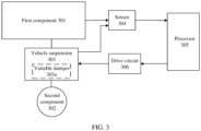
- FIG. 3 is a schematic diagram of a control system for a vehicle suspension according to an example.
- the control system for the vehicle suspension includes but is not limited to a first component 301, a second component 302, a vehicle suspension 303, a sensor 304, a processor 305, and a drive circuit 306.
- the vehicle suspension 303 is located between the first component 301 and the second component 302.
- the first component 301 is connected to one end of the vehicle suspension 303, and the vehicle suspension 303 bears the first component 301 (in other words, the first component 301 is a component that the vehicle suspension 303 bears).
- the first component 301 may also be referred to as a sprung mass, including a frame (namely, a body), an engine, a transmission, and the like.
- the second component 302 is connected to the other end of the vehicle suspension 303, and the second component 302 is configured to bear the vehicle suspension 303 and the first component 301.
- the second component 302 may also be referred to as an unsprung mass.
- the unsprung mass refers to a part other than the sprung mass in a vehicle, including a wheel (namely, a tire), a wheel rim, a brake disc, a caliper, a swing arm, a drive half shaft, and the like.
- the vehicle suspension 303 includes a variable damper 303a (which may also be referred to as a variable damping shock absorber) connected between the first component 301 and the second component 302.
- a variable damper 303a (which may also be referred to as a variable damping shock absorber) connected between the first component 301 and the second component 302.
- the variable damper 303a may be, for example, a magnetorheological damper or an electro-rheological damper, and may provide different first forces to the first component 301 based on different current values.
- the vehicle in this embodiment of this application may be an electric vehicle, a fuel vehicle, a motorcycle, or the like.
- the vehicle is an electric vehicle.
- the electric vehicle includes four wheels, one vehicle suspension is correspondingly disposed for each wheel, and vehicle suspensions may be mutually independent.
- the vehicle suspension provided in this embodiment of this application may be understood as any one of all vehicle suspensions disposed on the vehicle.
- the sensor 304 is configured to sense state variables or a state variable of the first component 301 and/or the second component 302, for example, a speed and/or an acceleration of the first component 301 and/or a speed of the second component 302.
- the sensor 304 includes a first speed sensor and a second speed sensor.
- the first speed sensor is configured to: sense a speed of the first component 301 in a height direction of the vehicle, and send the speed of the first component 301 in the height direction of the vehicle to the processor 305 or an input end of a differential circuit.
- the processor 305 or the differential circuit may calculate an acceleration (namely, a first acceleration) of the first component 301 in the height direction of the vehicle based on the speed of the first component 301 in the height direction of the vehicle.
- the first speed sensor may be disposed at a connection between the first component 301 and the vehicle suspension 303.
- the second speed sensor is configured to: sense a speed of the second component 302 in the height direction of the vehicle, and send the speed of the second component 302 in the height direction of the vehicle to the processor 305.
- the second speed sensor may be disposed at a connection between the vehicle suspension 303 and the second component 302.
- the sensor 304 further includes an acceleration sensor, and the acceleration sensor is configured to: sense the first acceleration of the first component 301, and send the first acceleration to the processor 305.
- the acceleration sensor may be disposed at the connection between the first component 301 and the vehicle suspension 303.
- a control method for a vehicle suspension provided in the embodiments of this application may be performed by the processor 305.
- the processor 305 is connected to the sensor 304, and the processor 305 may receive a signal sent by the sensor 304, for example, the state variables of the first component 301 and the second component 302, and determine, based on the received signal sent by the sensor 304, a first force that is to be provided by the variable damper to the first component 301. Further, the processor 305 calculates a target drive current value of the variable damper in real time based on the first force, generates a drive signal based on the target drive current value, and sends the drive signal to the drive circuit 306.
- the processor 305 may be a central processing unit (CPU), another general-purpose processor, a digital signal processor (DSP), an application-specific integrated circuit (ASIC), a field-programmable gate array (FPGA), another programmable logic device, a discrete gate, a transistor logic device, a discrete hardware component, or the like.
- CPU central processing unit
- DSP digital signal processor
- ASIC application-specific integrated circuit
- FPGA field-programmable gate array
- programmable logic device a discrete gate, a transistor logic device, a discrete hardware component, or the like.
- the drive circuit 306 may receive a drive signal sent by the processor 305, and output a target drive current to the variable damper 303a based on the drive signal.
- the target drive current value may be understood as a current value correspondingly required for outputting the first force by the variable damper 303a.
- the drive circuit 306 may include an electronic element, for example, may be a linear power supply or a switch-mode power supply.
- the drive signal may be a pulse width modulation (PWM) wave, and the PWM wave is used to control conduction duration of each switching transistor in the buck circuit, so that the drive circuit 306 outputs the target drive current.
- PWM pulse width modulation
- FIG. 4 is a schematic diagram of an equivalent model of a vehicle suspension according to another example.
- K2 represents an elastic element of the vehicle suspension
- D2 represents a variable damper of the vehicle suspension
- K1 represents a wheel.
- a displacement of a first component 401 in a height direction of a vehicle is represented as Z 1
- a displacement of a second component 402 in the height direction of the vehicle is represented as Z 2 .
- Both ends of each of the elastic element K2 and the variable damper D2 are separately connected to the first component 401 and the second component 402.
- the elastic element K2 and the variable damper D2 are configured to bear the first component 401.
- the wheel K1 is a part of the second component 402 and is configured to bear components, for example, the first component 401, the elastic element K2, and the variable damper D2, other than the wheel.
- FIG. 5 is a schematic diagram of a model of a control method for a vehicle suspension according to another example.
- the skyhook and the skyhook damper may be used to help understand how to suppress relative motion between the first component 401 and the skyhook.
- the skyhook and the skyhook damper are assumed to measure a swing degree of the first component 401. For example, the first component 401 is approaching the skyhook (in other words, swings upward in the height direction of the vehicle).
- the skyhook damper may provide a push force to the first component 401 to prevent the first component 401 from approaching the skyhook.
- the variable damper D2 provides a pull force to the first component 401 to prevent the first component 401 from approaching the skyhook.
- the first component 401 is being away from the skyhook (in other words, swings downward in the height direction of the vehicle).
- the skyhook damper may provide a pull force to the first component 401 to prevent the first component 401 from being away from the skyhook.
- variable damper D2 provides a push force to the first component 401 to prevent the first component 401 from being away from the skyhook.
- variable damper D2 cannot provide the push force, and can only maintain existing rigidity of the variable damper D2 to prevent the first component 401 from being away from the skyhook.
- a processor may obtain a speed of the first component relative to the second component in the height direction of the vehicle and a first speed, and determine a magnitude relationship between a product of the relative speed and the first speed and zero. It should be noted that the relative speed in this embodiment of this application is the speed of the first component relative to the second component in the height direction of the vehicle, and the first speed is a speed of the first component in the height direction of the vehicle.
- variable damper D2 may provide a first force to the first component 401 based on a first acceleration of the first component 401.
- variable damper D2 is connected to the processor, and the processor calculates, based on the first acceleration of the first component 401, the first force to be provided by the variable damper D2 to the first component 401. For example, the processor multiplies the first acceleration by a first preset control parameter to obtain a first product (namely, the first force to be provided by the variable damper D2 to the first component 401).
- Z ⁇ 1 is a second-order differential representation of Z 1 , in other words, the first acceleration may be obtained by differentiating the displacement Z 1 of the first component 401 in the height direction of the vehicle twice with respect to time.
- a bump in a driving process of the vehicle is mainly measured by an acceleration of the first component 401.
- the processor multiplies the first preset control parameter by the reference acceleration to obtain a fourth product.
- the processor determines the first force based on the first product and the fourth product.
- variable damper D2 may provide a first force to the first component 401 based on the relative speed and a second damping factor of the variable damper D2.
- the relative speed is multiplied by the second damping factor to obtain the first force.
- C 1 is an intrinsic factor (namely, the second damping factor) of the variable damper in a compressed state
- ⁇ 1 is the speed (namely, the first speed) of the first component 401 in the height direction of the vehicle
- ⁇ 2 is a speed of the second component 402 in the height direction of the vehicle
- ⁇ 1 - ⁇ 2 represents the speed of the first component 401 relative to the second component 402 in the height direction of the vehicle.
- the first acceleration of the first component 401 is sensed by an acceleration sensor.
- the acceleration sensor is disposed at a connection between the first component 401 and the variable damper D2 and/or the elastic element K2.
- the acceleration sensor may sense the first acceleration of the first component 401, and send the first acceleration sensed by the acceleration sensor to the processor.
- the first acceleration of the first component 401 is calculated by the processor after a speed sensor performs sensing.
- the speed sensor is disposed at a connection between the first component 401 and the variable damper D2 and/or the elastic element K2.
- the speed sensor may sense the speed of the first component 401 in the height direction of the vehicle, and send the speed to the processor or a differential unit.
- the processor or the differential unit performs a differential operation on the speed of the first component 401 in the height direction of the vehicle with respect to time to obtain the first acceleration of the first component 401 in the height direction of the vehicle.
- the processor may determine a target drive current value based on the first force and the relative speed.
- the processor may obtain an output characteristic of the vehicle suspension, and the output characteristic of the vehicle suspension may be understood as a relationship between the relative speed, the first force, and a drive current. In other words, for the vehicle suspension, there is a mapping relationship between first forces and drive currents when relative speeds are different.
- FIG. 6 is a schematic diagram of an output characteristic of a vehicle suspension according to yet another example.
- the relative speed may be sensed by a speed sensor.
- a first speed sensor is disposed at a connection between the first component 401 and the variable damper D2 and/or the elastic element K2 to sense a speed of the first component 401.
- a second speed sensor is disposed at a connection between the second component 402 and the variable damper D2 and/or the elastic element K2 to sense a speed of the second component 402.
- the speed of the second component 402 is subtracted from the speed of the first component 401 to obtain the speed of the first component 401 relative to the second component 402.
- the processor performs fitting on the first force and the relative speed. For example, an intersection point (namely, a black point shown in FIG. 6 ) of the first force and the relative speed in a two-dimensional coordinate system shown in FIG. 6 is calculated. In this case, the black point is exactly located on a curve of a current 1, and a magnitude of the current 1 is the target drive current value. In another example, if the foregoing intersection point is not located on any curve shown in FIG.
- a half of a sum of current values corresponding to the two curves near the intersection point may be used as the target drive current value, or a current value corresponding to a curve closest to the intersection point may be obtained as the target drive current value. It may be understood that only example descriptions of how to determine the target drive current value based on the first force and the relative speed are provided herein, and the descriptions should not be construed as limiting this embodiment of this application.
- the output characteristic of the vehicle suspension may be specifically represented as a table.
- the table includes a plurality of first forces, a plurality of relative speeds, and a plurality of target drive current values. Each piece of data in the table is obtained through a plurality of tests. Examples are shown in Table 1. Table 1 First force/(N) Relative speed/(m/s) Target drive current value/(A) 10 2 0.9 20 5 4 100 2 6 ...
- the processor may determine, by querying Table 1, that the target drive current value is 4 A.
- the processor cannot find a corresponding target drive current in Table 1, and the processor may perform search within a preset range of first forces to determine the target drive current value, or the processor performs search within a preset range of relative speeds to determine the target drive current value. It should be noted that how to perform data processing on the first force and the relative speed is not limited in this embodiment of this application.
- the output characteristic of the vehicle suspension may be specifically represented by a formula.
- a formula may be obtained by performing fitting on a plurality of first forces, a plurality of relative speeds, and a plurality of target drive current values obtained through a plurality of tests. Independent variables are the first force and the relative speed, and a dependent variable is the target drive current value.
- the processor may substitute the calculated first force and the obtained relative speed into the formula to calculate the target drive current value.
- the processor generates a drive signal based on the target drive current value, and sends the drive signal to a drive circuit of the variable damper D2.
- An input end of the drive circuit is connected to the processor, and an output end of the drive circuit is connected to the variable damper D2.
- the drive circuit outputs a target drive current whose value is the target drive current value to the variable damper D2 based on the drive signal.
- the drive circuit may be specifically a linear power supply or a switch-mode power supply, for example, a buck circuit.
- the drive signal is a PWM wave, and the PWM wave controls conduction duration of each switching transistor in the buck circuit, so that the buck circuit outputs the target drive current to the variable damper D2.
- the variable damper D2 may provide the first force to the first component 401 based on the target drive current.
- the processor further compares the first force with a maximum damping force of the variable damper D2.
- the maximum damping force of the variable damper D2 is an intrinsic attribute of the variable damper D2 and is a fixed value.
- the variable damper D2 uses the maximum damping force of the variable damper D2 as the first force, and provides the first force to the first component 401.
- the processor determines the target drive current value by using the maximum damping force of the variable damper D2 as the first force.
- the first force to be provided by the variable damper to the first component is directly controlled, and the first acceleration of the first component is introduced in a control process of the first force to perform closed-loop control, to implement accurate control over the first acceleration of the first component, thereby effectively reducing bumps in a driving process of the vehicle and improving vehicle ride comfort.
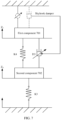
- FIG. 7 is a schematic diagram of another model of a control method for a vehicle suspension to which the invention relates.
- K4 represents an elastic element of the vehicle suspension
- D3 represents a variable damper of the vehicle suspension
- K3 represents a wheel.
- a displacement of a first component 701 in a height direction of a vehicle is represented as Z 3
- a displacement of a second component 702 in the height direction of the vehicle is represented as Z 4 .
- a processor obtains a relative speed and a first speed, and determines a magnitude relationship between a product of the relative speed and the first speed and zero.
- the processor multiplies a first acceleration by a first preset control parameter to obtain a first product.
- the processor multiplies a speed (namely, the first speed) of the first component 701 in the height direction of the vehicle by a second preset control parameter to obtain a second product.
- the processor may determine, based on the first product and the second product, a first force that is to be provided by the variable damper D3 to the first component 701.
- a bump in a driving process of the vehicle is mainly measured by an acceleration of the first component 701.
- the processor multiplies the first preset control parameter by the reference acceleration to obtain a fourth product.
- the processor determines the first force based on the first product, the second product, and the fourth product.
- Z ⁇ 3 * may be preset to 0.
- variable damper D3 may provide the first force to the first component 701 based on the relative speed and a second damping factor of the variable damper D3.
- the relative speed is multiplied by the second damping factor to obtain the first force.
- Formula 6 and Formula 7 may be combined to obtain the following formula representation:
- F ⁇ 1 ⁇ ⁇ C a .
- the first speed of the first component is introduced, so that the first acceleration of the first component can be more accurately controlled, thereby further improving vehicle ride comfort.
- the processor multiplies a first damping factor of the variable damper D3 by the relative speed to obtain a third product.
- the processor determines the first force based on the first product, the second product, the third product, and the fourth product.
- the damping force of the variable damper is considered.
- the damping force of the variable damper is introduced, so that the first acceleration of the first component can be more accurately controlled, thereby further improving vehicle ride comfort.
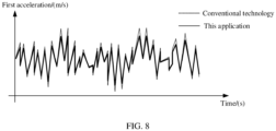
- FIG. 8 is a schematic diagram of a waveform of a first acceleration according to an embodiment of this application. As shown in FIG.
- a dotted-line waveform is a waveform of a first acceleration when the conventional technology is used
- a solid-line waveform is a waveform of a first acceleration when the embodiments of this application are used. It may be understood that vehicle ride comfort may be measured by a first acceleration of a first component. A smaller first acceleration indicates smaller swing amplitude of the first component, a lower vehicle bumping degree, and higher ride comfort. Conversely, a larger first acceleration indicates larger swing amplitude of the first component, a higher vehicle bumping degree, and lower ride comfort. It can be learned from the waveform diagram shown in FIG.
- the invention also provides a control method for a vehicle suspension.
- the method is applicable to the vehicles described in FIG. 7 according to the invention.
- the method may be performed by a processor.
- the method includes the following steps.
- the processor determines, based on a first acceleration of a first component, a first force that is to be provided by a variable damper to the first component, to control a displacement of the first component relative to a second component in a height direction of a vehicle.
- the processor determines, based on a first product of the first acceleration and a first preset control parameter, the first force that is to be provided by the variable damper to the first component, where the first acceleration is an acceleration of the first component in the height direction of the vehicle.
- the processor may determine, based on the first product and a second product, the first force that is to be provided by the variable damper to the first component, where the second product is a product of a first speed and a second preset control parameter, and the first speed is a speed of the first component in the height direction of the vehicle.
- the processor may determine, based on the first product, the second product, and a third product, the first force that is to be provided by the variable damper to the first component, where the third product is a product of a relative speed and a first damping factor of the variable damper, and the relative speed is a speed of the first component relative to the second component in the height direction of the vehicle.
- the processor may determine, based on the first product and a fourth product, the first force that is to be provided by the variable damper to the first component, where the fourth product is a product of a reference acceleration and the first preset control parameter.
- the method may further include: The processor may determine a target drive current value based on the first force and the relative speed, where the relative speed is the speed of the first component relative to the second component in the height direction of the vehicle.
- the processor may generate a drive signal based on the target drive current value, and send the drive signal to a drive circuit of the variable damper, so that the drive circuit of the variable damper outputs a target drive current whose value is the target drive current value to the variable damper based on the drive signal.
- a product of the relative speed and the first speed is greater than zero.
- the relative speed is the speed of the first component relative to the second component in the height direction of the vehicle
- the first speed is the speed of the first component in the height direction of the vehicle.
- the processor determines, based on the relative speed and a second damping factor of the variable damper, the first force that is to be provided by the variable damper to the first component.
- the processor uses the maximum damping force of the variable damper as the first force.
- An embodiment not in accordance with the invention further provides a vehicle suspension.
- the vehicle suspension is located between a first component and a second component, the first component is a component that the vehicle suspension bears, and the second component is configured to bear the vehicle suspension and the first component.
- the vehicle suspension includes a variable damper connected between the first component and the second component, and the variable damper may be configured to implement the functions described in FIG. 7 to FIG. 8 .
- the invention further provides a control device for a vehicle suspension.
- the control device includes a transceiver, a processor, and a memory.
- the transceiver, the processor, and the memory are connected by using a bus system.
- the memory is configured to store instructions, and the processor is configured to invoke the instructions stored in the memory, to implement the functions described in FIG. 3 to FIG. 8 .
- the program may be stored in a computer-readable storage medium. When the program runs, the steps of the method embodiments are performed.
- the foregoing storage medium includes: any medium that can store program code, such as a read-only memory (ROM), a random access memory (RAM), a magnetic disk, or an optical disc.
- the integrated unit When the foregoing integrated unit is implemented in the form of a software functional unit and sold or used as an independent product, the integrated unit may be stored in a computer-readable storage medium. Based on such an understanding, the technical solutions in the present invention may be essentially or the part that contributes to the conventional technology may be implemented in the form of a software product.
- the computer software product is stored in a storage medium, and includes several instructions for instructing a computer device (which may be a personal computer, server, or network device) to perform all or some steps of the methods provided in the embodiments of the present invention.
- the foregoing storage medium includes any medium that can store program code, for example, a mobile storage device, a ROM, a RAM, a magnetic disk, or an optical disc.
Landscapes
- Engineering & Computer Science (AREA)
- Mechanical Engineering (AREA)
- Vehicle Body Suspensions (AREA)
- Fluid-Damping Devices (AREA)
Claims (7)
- Fahrzeug, wobei das Fahrzeug eine erste Komponente (701), eine zweite Komponente (702) und eine Fahrzeugaufhängung umfasst, wobei die Fahrzeugaufhängung zwischen der ersten Komponente (701) und der zweiten Komponente (702) angeordnet ist; und die erste Komponente (701) eine Komponente ist, die die Fahrzeugaufhängung trägt, die zweite Komponente (702) konfiguriert ist, die Fahrzeugaufhängung und die erste Komponente (701) zu tragen, und die Fahrzeugaufhängung einen variablen Dämpfer (D3) umfasst, der zwischen der ersten Komponente (701) und der zweiten Komponente (702) verbunden ist; undder variable Dämpfer (D3) konfiguriert ist, eine erste Kraft (F1) der ersten Komponente (701) bereitzustellen, um eine Versetzung (Z3) der ersten Komponente (701) relativ zu der zweiten Komponente (702) in einer Höhenrichtung des Fahrzeugs zu steuern;wobei der variable Dämpfer (D3) konfiguriert ist, die erste Kraft der ersten Komponente (701) gemäß der folgenden Formel bereitzustellen:
 wobei:Ca ein erster im Voraus eingestellter Steuerparameter ist,Cs ein zweiter im Voraus eingestellter Steuerparameter ist,C 1 der Dämpfungsfaktor des variablen Dämpfers in einem komprimierten Zustand ist,C 2 der Dämpfungsfaktor des variablen Dämpfers in einem gestreckten Zustand ist,
 Z̈ 3 die Beschleunigung der ersten Komponente in der Höhenrichtung des Fahrzeugs ist,Ż 3 die Geschwindigkeit der ersten Komponente in der Höhenrichtung des Fahrzeugs ist,Ż 4 die Geschwindigkeit der zweiten Komponente in der Höhenrichtung des Fahrzeugs ist undŻ 3 - Ż 4 die relative Geschwindigkeit der ersten Komponente relativ zu der zweiten Komponente in der Höhenrichtung des Fahrzeugs repräsentiert.
 - Fahrzeug nach Anspruch 1, wobei das Fahrzeug ferner eine Antriebsschaltung (306) umfasst und die Antriebsschaltung (306) mit dem variablen Dämpfer (D3) verbunden ist; und
die Antriebsschaltung (306) konfiguriert ist zum: Empfangen eines Antriebssignals und Ausgeben eines Ziel-Antriebsstroms, dessen Wert ein Ziel-Antriebsstromwert ist, zu dem variablen Dämpfer (D3) basierend auf dem Antriebssignal, wobei der Ziel-Antriebsstromwert basierend auf der ersten Kraft und der relativen Geschwindigkeit bestimmt wird. - Fahrzeug nach einem der Ansprüche 1 bis 2, wobei, wenn die erste Kraft größer als eine maximale Dämpfungskraft des variablen Dämpfers (D3) ist, der variable Dämpfer (D3) konfiguriert ist zum: Verwenden der maximalen Dämpfungskraft des variablen Dämpfers (D3) als die erste Kraft.
- Steuerverfahren für eine Fahrzeugaufhängung eines Fahrzeugs, wobei die Fahrzeugaufhängung zwischen einer ersten Komponente (701) und einer zweiten Komponente (702) angeordnet ist, die erste Komponente (701) eine Komponente ist, die die Fahrzeugaufhängung trägt, die zweite Komponente (702) konfiguriert ist, die Fahrzeugaufhängung und die erste Komponente (701) zu tragen, die Fahrzeugaufhängung einen variablen Dämpfer (D3) umfasst, der zwischen der ersten Komponente (701) und der zweiten Komponente (702) verbunden ist, und das Steuerverfahren Folgendes umfasst:Bestimmen einer ersten Kraft (F1), die durch den variablen Dämpfer (D3) der ersten Komponente (701) bereitgestellt werden soll, um eine Versetzung (Z3) der ersten Komponente (701) relativ zu der zweiten Komponente (702) in einer Höhenrichtung des Fahrzeugs zu steuern;wobei der variable Dämpfer (D3) die erste Kraft der ersten Komponente (701) gemäß der folgenden Formel bereitstellt:
 wobei:Ca ein erster im Voraus eingestellter Steuerparameter ist,Cs ein zweiter im Voraus eingestellter Steuerparameter ist,C 1 der Dämpfungsfaktor des variablen Dämpfers in einem komprimierten Zustand ist,C 2 der Dämpfungsfaktor des variablen Dämpfers in einem gestreckten Zustand ist,
 Z̈ 3 die Beschleunigung der ersten Komponente in der Höhenrichtung des Fahrzeugs ist,Ż 3 die Geschwindigkeit der ersten Komponente in der Höhenrichtung des Fahrzeugs ist,Ż 4 die Geschwindigkeit der zweiten Komponente in der Höhenrichtung des Fahrzeugs ist undŻ 3 - Ż 4 die relative Geschwindigkeit der ersten Komponente relativ zu der zweiten Komponente in der Höhenrichtung des Fahrzeugs repräsentiert.
 - Steuerverfahren nach Anspruch 4, wobei das Verfahren ferner Folgendes umfasst:Bestimmen eines Ziel-Antriebsstromwerts basierend auf der ersten Kraft und der relativen Geschwindigkeit; undErzeugen eines Antriebssignals basierend auf dem Ziel-Antriebsstromwert und Senden des Antriebssignals an eine Antriebsschaltung (306) des variablen Dämpfers (D3), so dass die Antriebsschaltung (306) des variablen Dämpfers (D3) einen Ziel-Antriebsstrom, dessen Wert der Ziel-Antriebsstromwert ist, zu dem variablen Dämpfer (D3) basierend auf dem Antriebssignal ausgibt.
- Steuerverfahren nach einem der Ansprüche 4 bis 5, wobei das Verfahren ferner Folgendes umfasst:
wenn die erste Kraft größer als eine maximale Dämpfungskraft des variablen Dämpfers (D3) ist, Verwenden der maximalen Dämpfungskraft des variablen Dämpfers (D3) als die erste Kraft. - Steuergerät für eine Fahrzeugaufhängung, wobei das Steuergerät einen Sender/Empfänger, einen Prozessor und einen Speicher umfasst und der Sender/Empfänger, der Prozessor und die Speicher unter Verwendung eines Bussystems verbunden sind;der Speicher konfiguriert ist zum Speichern von Anweisungen; undder Prozessor konfiguriert ist zum Aufrufen der in dem Speicher gespeicherten Anweisungen, um das Fahrzeug nach einem der Ansprüche 1 bis 3 zu veranlassen, das Verfahren nach einem der Ansprüche 4 bis 6 durchzuführen.
Applications Claiming Priority (1)
| Application Number | Priority Date | Filing Date | Title |
|---|---|---|---|
| CN202011530881.XA CN112572086A (zh) | 2020-12-22 | 2020-12-22 | 车辆、车辆悬架的控制方法及其相关设备 |
Publications (2)
| Publication Number | Publication Date |
|---|---|
| EP4019302A1 EP4019302A1 (de) | 2022-06-29 |
| EP4019302B1 true EP4019302B1 (de) | 2024-07-31 |
Family
ID=75139035
Family Applications (1)
| Application Number | Title | Priority Date | Filing Date |
|---|---|---|---|
| EP21214344.0A Active EP4019302B1 (de) | 2020-12-22 | 2021-12-14 | Fahrzeug, steuerungsverfahren für fahrzeugaufhängung und zugehörige steuervorrichtung |
Country Status (4)
| Country | Link |
|---|---|
| US (1) | US11897300B2 (de) |
| EP (1) | EP4019302B1 (de) |
| JP (1) | JP7293326B2 (de) |
| CN (1) | CN112572086A (de) |
Families Citing this family (2)
| Publication number | Priority date | Publication date | Assignee | Title |
|---|---|---|---|---|
| CN116021939B (zh) * | 2021-10-26 | 2025-04-08 | 比亚迪股份有限公司 | 半主动悬架控制方法及控制装置、存储介质及车辆 |
| CN114654957A (zh) * | 2022-04-08 | 2022-06-24 | 成都明然智能科技有限公司 | 悬架的控制方法及车辆 |
Citations (1)
| Publication number | Priority date | Publication date | Assignee | Title |
|---|---|---|---|---|
| US5884921A (en) * | 1996-08-29 | 1999-03-23 | Toyota Jidosha Kabushiki Kaisha | Electric control apparatus for damper device in suspension system of automotive vehicle |
Family Cites Families (32)
| Publication number | Priority date | Publication date | Assignee | Title |
|---|---|---|---|---|
| DE4243979C2 (de) * | 1991-12-26 | 1998-10-01 | Atsugi Unisia Corp | Steuervorrichtung zum Einstellen der Dämpfungscharakteristik einer Fahrzeugaufhängung |
| JPH05238233A (ja) * | 1992-03-02 | 1993-09-17 | Toyota Motor Corp | サスペンションの制御装置 |
| JP3374208B2 (ja) * | 1995-07-06 | 2003-02-04 | 株式会社日立ユニシアオートモティブ | 車両懸架装置 |
| JP3118414B2 (ja) * | 1996-05-22 | 2000-12-18 | 株式会社豊田中央研究所 | 車両のばね上ばね下相対速度算出装置 |
| US6701235B2 (en) * | 2000-08-31 | 2004-03-02 | Tokico Ltd. | Suspension control system |
| JP2002321513A (ja) | 2001-04-27 | 2002-11-05 | Tokico Ltd | サスペンション制御装置 |
| CN100458766C (zh) * | 2002-01-11 | 2009-02-04 | 活力震动公司 | 半有源的减震器控制系统 |
| KR100574898B1 (ko) * | 2003-11-26 | 2006-04-27 | 주식회사 만도 | 전자 제어 현가 장치와 이를 이용한 감쇠력 제어 방법 |
| JP4546308B2 (ja) * | 2005-03-30 | 2010-09-15 | 本田技研工業株式会社 | 可変減衰力ダンパーの制御装置 |
| TWM313192U (en) * | 2006-12-05 | 2007-06-01 | Wen-Hua Guo | Automatic control device for electric current fluid variation vibration absorber |
| JP5246269B2 (ja) * | 2008-12-25 | 2013-07-24 | トヨタ自動車株式会社 | 減衰力制御装置 |
| JP5293264B2 (ja) | 2009-02-25 | 2013-09-18 | 日産自動車株式会社 | 減衰力制御装置、及び減衰力制御方法 |
| CN102205781B (zh) * | 2010-03-31 | 2015-04-01 | 日立汽车系统株式会社 | 悬架控制装置及车辆控制装置 |
| CN102582389B (zh) * | 2012-03-02 | 2014-05-28 | 江苏大学 | 一种基于虚拟阻尼的车辆悬架控制方法 |
| CN102729760B (zh) * | 2012-07-17 | 2014-06-18 | 山东理工大学 | 汽车半主动悬架系统实时最佳阻尼控制算法 |
| JP2017171156A (ja) * | 2016-03-24 | 2017-09-28 | トヨタ自動車株式会社 | 車両用減衰力制御装置 |
| CN105946496A (zh) * | 2016-04-27 | 2016-09-21 | 东华大学 | 一种基于天棚控制算法的悬挂控制系统 |
| CN105857003B (zh) * | 2016-05-11 | 2018-04-17 | 江苏大学 | 一种馈能悬架系统的改进天棚控制方法 |
| DE112017004865B4 (de) * | 2016-09-28 | 2023-05-25 | Hitachi Astemo, Ltd. | Federungssteuervorrichtung |
| CN106515348B (zh) | 2016-12-23 | 2020-04-28 | 浙江孔辉汽车科技有限公司 | 一种用于车辆悬架系统的智能加速度阻尼半主动控制方法 |
| KR102245115B1 (ko) * | 2017-02-24 | 2021-04-28 | 히다치 아스테모 가부시키가이샤 | 차량 거동 제어 장치 |
| JP6589943B2 (ja) * | 2017-06-29 | 2019-10-16 | トヨタ自動車株式会社 | 車両走行制御システム |
| JP6638707B2 (ja) * | 2017-07-27 | 2020-01-29 | トヨタ自動車株式会社 | サスペンション制御システム |
| JP2019031240A (ja) * | 2017-08-09 | 2019-02-28 | アイシン精機株式会社 | 減衰力可変ダンパの制御装置、制御システム、方法及びプログラム |
| CN107825930B (zh) * | 2017-12-08 | 2019-01-25 | 吉林大学 | 一种用于车辆悬架系统的智能模糊混合棚半主动控制方法 |
| KR102414888B1 (ko) * | 2018-03-27 | 2022-07-01 | 히다치 아스테모 가부시키가이샤 | 서스펜션 제어 장치 |
| JP7059791B2 (ja) * | 2018-05-16 | 2022-04-26 | トヨタ自動車株式会社 | 減衰力制御装置 |
| JP2020011597A (ja) * | 2018-07-18 | 2020-01-23 | 本田技研工業株式会社 | 車両のサスペンションシステム |
| CN108891220B (zh) | 2018-07-19 | 2020-07-28 | 燕山大学 | 一种车辆半主动悬架系统的天棚控制改进方法 |
| US12263709B2 (en) * | 2018-10-12 | 2025-04-01 | Hitachi Astemo, Ltd. | Vehicle suspension control device including a damping force adjustable shock absorber |
| JP6734912B2 (ja) * | 2018-12-24 | 2020-08-05 | 本田技研工業株式会社 | 車両のサスペンション制御装置 |
| KR102757181B1 (ko) * | 2019-08-20 | 2025-01-20 | 현대자동차주식회사 | 차량 및 그 제어 방법 |
-
2020
- 2020-12-22 CN CN202011530881.XA patent/CN112572086A/zh active Pending
-
2021
- 2021-12-14 EP EP21214344.0A patent/EP4019302B1/de active Active
- 2021-12-15 US US17/552,285 patent/US11897300B2/en active Active
- 2021-12-21 JP JP2021206681A patent/JP7293326B2/ja active Active
Patent Citations (1)
| Publication number | Priority date | Publication date | Assignee | Title |
|---|---|---|---|---|
| US5884921A (en) * | 1996-08-29 | 1999-03-23 | Toyota Jidosha Kabushiki Kaisha | Electric control apparatus for damper device in suspension system of automotive vehicle |
Also Published As
| Publication number | Publication date |
|---|---|
| CN112572086A (zh) | 2021-03-30 |
| JP2022099304A (ja) | 2022-07-04 |
| JP7293326B2 (ja) | 2023-06-19 |
| EP4019302A1 (de) | 2022-06-29 |
| US20220194157A1 (en) | 2022-06-23 |
| US11897300B2 (en) | 2024-02-13 |
Similar Documents
| Publication | Publication Date | Title |
|---|---|---|
| EP2250038B1 (de) | Verfahren und vorrichtung zur steuerung eines halbaktiven aufhängungssystems für motorräder | |
| CN116101008B (zh) | 基于整车性能的半主动悬架控制方法、系统及车辆 | |
| US9963006B2 (en) | Damper control device | |
| JP4972440B2 (ja) | 減衰力可変ダンパの制御装置 | |
| CN100404293C (zh) | 电控悬架装置以及减振力控制方法 | |
| JP2004237825A (ja) | 車両用電磁サスペンション装置と車両用電磁サスペンション装置のモータ制御方法 | |
| WO2021259004A1 (zh) | 基于车身姿态调节的阻尼可调悬架的控制方法 | |
| CN106515348A (zh) | 一种用于车辆悬架系统的智能加速度阻尼半主动控制方法 | |
| EP4019302B1 (de) | Fahrzeug, steuerungsverfahren für fahrzeugaufhängung und zugehörige steuervorrichtung | |
| JP4926945B2 (ja) | 車両のショックアブソーバシステムを制御する方法、セミアクティブショックアブソーバおよびショックアブソーバシステム | |
| JP2006109642A (ja) | 車両の制駆動力制御装置 | |
| CN109203903B (zh) | 悬架控制系统 | |
| JP2008247261A (ja) | サスペンション制御装置 | |
| US10759248B2 (en) | Traveling control system for vehicle | |
| US20220118812A1 (en) | Suspension stroke related value estimation device and method | |
| US6871731B2 (en) | Adjustable shock absorber for a motor vehicle | |
| EP0579182B1 (de) | Aktive Fahrzeugfederung, insbesondere Fahrerhausfederung eines Nutzfahrzeuges | |
| JP2013241076A (ja) | サスペンション制御装置 | |
| CN119388938A (zh) | 一种电动车辆的轮毂电机悬架系统的ampc控制方法 | |
| JP2012001160A (ja) | ダンパ制御装置 | |
| JP2010095211A (ja) | 車両のサスペンション装置 | |
| Kayisli et al. | Sliding mode control of vehicle suspension system under different road conditions | |
| JP2014043199A (ja) | サスペンション制御装置 | |
| JP2010052488A (ja) | サスペンション制御装置 | |
| Liu et al. | Nonlinear Force Model of Electromagnetic Damper and Its Influence on Vibration Control |
Legal Events
| Date | Code | Title | Description |
|---|---|---|---|
| PUAI | Public reference made under article 153(3) epc to a published international application that has entered the european phase |
Free format text: ORIGINAL CODE: 0009012 |
|
| STAA | Information on the status of an ep patent application or granted ep patent |
Free format text: STATUS: THE APPLICATION HAS BEEN PUBLISHED |
|
| AK | Designated contracting states |
Kind code of ref document: A1 Designated state(s): AL AT BE BG CH CY CZ DE DK EE ES FI FR GB GR HR HU IE IS IT LI LT LU LV MC MK MT NL NO PL PT RO RS SE SI SK SM TR |
|
| STAA | Information on the status of an ep patent application or granted ep patent |
Free format text: STATUS: REQUEST FOR EXAMINATION WAS MADE |
|
| 17P | Request for examination filed |
Effective date: 20220920 |
|
| RBV | Designated contracting states (corrected) |
Designated state(s): AL AT BE BG CH CY CZ DE DK EE ES FI FR GB GR HR HU IE IS IT LI LT LU LV MC MK MT NL NO PL PT RO RS SE SI SK SM TR |
|
| STAA | Information on the status of an ep patent application or granted ep patent |
Free format text: STATUS: EXAMINATION IS IN PROGRESS |
|
| 17Q | First examination report despatched |
Effective date: 20221221 |
|
| GRAP | Despatch of communication of intention to grant a patent |
Free format text: ORIGINAL CODE: EPIDOSNIGR1 |
|
| STAA | Information on the status of an ep patent application or granted ep patent |
Free format text: STATUS: GRANT OF PATENT IS INTENDED |
|
| INTG | Intention to grant announced |
Effective date: 20240325 |
|
| GRAS | Grant fee paid |
Free format text: ORIGINAL CODE: EPIDOSNIGR3 |
|
| GRAA | (expected) grant |
Free format text: ORIGINAL CODE: 0009210 |
|
| STAA | Information on the status of an ep patent application or granted ep patent |
Free format text: STATUS: THE PATENT HAS BEEN GRANTED |
|
| AK | Designated contracting states |
Kind code of ref document: B1 Designated state(s): AL AT BE BG CH CY CZ DE DK EE ES FI FR GB GR HR HU IE IS IT LI LT LU LV MC MK MT NL NO PL PT RO RS SE SI SK SM TR |
|
| REG | Reference to a national code |
Ref country code: CH Ref legal event code: EP Ref country code: GB Ref legal event code: FG4D |
|
| REG | Reference to a national code |
Ref country code: DE Ref legal event code: R096 Ref document number: 602021016437 Country of ref document: DE |
|
| REG | Reference to a national code |
Ref country code: IE Ref legal event code: FG4D |
|
| REG | Reference to a national code |
Ref country code: LT Ref legal event code: MG9D |
|
| REG | Reference to a national code |
Ref country code: NL Ref legal event code: MP Effective date: 20240731 |
|
| PG25 | Lapsed in a contracting state [announced via postgrant information from national office to epo] |
Ref country code: PT Free format text: LAPSE BECAUSE OF FAILURE TO SUBMIT A TRANSLATION OF THE DESCRIPTION OR TO PAY THE FEE WITHIN THE PRESCRIBED TIME-LIMIT Effective date: 20241202 |
|
| REG | Reference to a national code |
Ref country code: AT Ref legal event code: MK05 Ref document number: 1708149 Country of ref document: AT Kind code of ref document: T Effective date: 20240731 |
|
| PG25 | Lapsed in a contracting state [announced via postgrant information from national office to epo] |
Ref country code: PT Free format text: LAPSE BECAUSE OF FAILURE TO SUBMIT A TRANSLATION OF THE DESCRIPTION OR TO PAY THE FEE WITHIN THE PRESCRIBED TIME-LIMIT Effective date: 20241202 |
|
| PG25 | Lapsed in a contracting state [announced via postgrant information from national office to epo] |
Ref country code: NO Free format text: LAPSE BECAUSE OF FAILURE TO SUBMIT A TRANSLATION OF THE DESCRIPTION OR TO PAY THE FEE WITHIN THE PRESCRIBED TIME-LIMIT Effective date: 20241031 |
|
| PG25 | Lapsed in a contracting state [announced via postgrant information from national office to epo] |
Ref country code: NL Free format text: LAPSE BECAUSE OF FAILURE TO SUBMIT A TRANSLATION OF THE DESCRIPTION OR TO PAY THE FEE WITHIN THE PRESCRIBED TIME-LIMIT Effective date: 20240731 Ref country code: PL Free format text: LAPSE BECAUSE OF FAILURE TO SUBMIT A TRANSLATION OF THE DESCRIPTION OR TO PAY THE FEE WITHIN THE PRESCRIBED TIME-LIMIT Effective date: 20240731 Ref country code: GR Free format text: LAPSE BECAUSE OF FAILURE TO SUBMIT A TRANSLATION OF THE DESCRIPTION OR TO PAY THE FEE WITHIN THE PRESCRIBED TIME-LIMIT Effective date: 20241101 Ref country code: FI Free format text: LAPSE BECAUSE OF FAILURE TO SUBMIT A TRANSLATION OF THE DESCRIPTION OR TO PAY THE FEE WITHIN THE PRESCRIBED TIME-LIMIT Effective date: 20240731 |
|
| PG25 | Lapsed in a contracting state [announced via postgrant information from national office to epo] |
Ref country code: BG Free format text: LAPSE BECAUSE OF FAILURE TO SUBMIT A TRANSLATION OF THE DESCRIPTION OR TO PAY THE FEE WITHIN THE PRESCRIBED TIME-LIMIT Effective date: 20240731 |
|
| PG25 | Lapsed in a contracting state [announced via postgrant information from national office to epo] |
Ref country code: LV Free format text: LAPSE BECAUSE OF FAILURE TO SUBMIT A TRANSLATION OF THE DESCRIPTION OR TO PAY THE FEE WITHIN THE PRESCRIBED TIME-LIMIT Effective date: 20240731 |
|
| PG25 | Lapsed in a contracting state [announced via postgrant information from national office to epo] |
Ref country code: AT Free format text: LAPSE BECAUSE OF FAILURE TO SUBMIT A TRANSLATION OF THE DESCRIPTION OR TO PAY THE FEE WITHIN THE PRESCRIBED TIME-LIMIT Effective date: 20240731 Ref country code: IS Free format text: LAPSE BECAUSE OF FAILURE TO SUBMIT A TRANSLATION OF THE DESCRIPTION OR TO PAY THE FEE WITHIN THE PRESCRIBED TIME-LIMIT Effective date: 20241130 |
|
| PG25 | Lapsed in a contracting state [announced via postgrant information from national office to epo] |
Ref country code: HR Free format text: LAPSE BECAUSE OF FAILURE TO SUBMIT A TRANSLATION OF THE DESCRIPTION OR TO PAY THE FEE WITHIN THE PRESCRIBED TIME-LIMIT Effective date: 20240731 |
|
| PG25 | Lapsed in a contracting state [announced via postgrant information from national office to epo] |
Ref country code: ES Free format text: LAPSE BECAUSE OF FAILURE TO SUBMIT A TRANSLATION OF THE DESCRIPTION OR TO PAY THE FEE WITHIN THE PRESCRIBED TIME-LIMIT Effective date: 20240731 Ref country code: RS Free format text: LAPSE BECAUSE OF FAILURE TO SUBMIT A TRANSLATION OF THE DESCRIPTION OR TO PAY THE FEE WITHIN THE PRESCRIBED TIME-LIMIT Effective date: 20241031 |
|
| PG25 | Lapsed in a contracting state [announced via postgrant information from national office to epo] |
Ref country code: RS Free format text: LAPSE BECAUSE OF FAILURE TO SUBMIT A TRANSLATION OF THE DESCRIPTION OR TO PAY THE FEE WITHIN THE PRESCRIBED TIME-LIMIT Effective date: 20241031 Ref country code: PL Free format text: LAPSE BECAUSE OF FAILURE TO SUBMIT A TRANSLATION OF THE DESCRIPTION OR TO PAY THE FEE WITHIN THE PRESCRIBED TIME-LIMIT Effective date: 20240731 Ref country code: NO Free format text: LAPSE BECAUSE OF FAILURE TO SUBMIT A TRANSLATION OF THE DESCRIPTION OR TO PAY THE FEE WITHIN THE PRESCRIBED TIME-LIMIT Effective date: 20241031 Ref country code: NL Free format text: LAPSE BECAUSE OF FAILURE TO SUBMIT A TRANSLATION OF THE DESCRIPTION OR TO PAY THE FEE WITHIN THE PRESCRIBED TIME-LIMIT Effective date: 20240731 Ref country code: LV Free format text: LAPSE BECAUSE OF FAILURE TO SUBMIT A TRANSLATION OF THE DESCRIPTION OR TO PAY THE FEE WITHIN THE PRESCRIBED TIME-LIMIT Effective date: 20240731 Ref country code: IS Free format text: LAPSE BECAUSE OF FAILURE TO SUBMIT A TRANSLATION OF THE DESCRIPTION OR TO PAY THE FEE WITHIN THE PRESCRIBED TIME-LIMIT Effective date: 20241130 Ref country code: HR Free format text: LAPSE BECAUSE OF FAILURE TO SUBMIT A TRANSLATION OF THE DESCRIPTION OR TO PAY THE FEE WITHIN THE PRESCRIBED TIME-LIMIT Effective date: 20240731 Ref country code: GR Free format text: LAPSE BECAUSE OF FAILURE TO SUBMIT A TRANSLATION OF THE DESCRIPTION OR TO PAY THE FEE WITHIN THE PRESCRIBED TIME-LIMIT Effective date: 20241101 Ref country code: FI Free format text: LAPSE BECAUSE OF FAILURE TO SUBMIT A TRANSLATION OF THE DESCRIPTION OR TO PAY THE FEE WITHIN THE PRESCRIBED TIME-LIMIT Effective date: 20240731 Ref country code: ES Free format text: LAPSE BECAUSE OF FAILURE TO SUBMIT A TRANSLATION OF THE DESCRIPTION OR TO PAY THE FEE WITHIN THE PRESCRIBED TIME-LIMIT Effective date: 20240731 Ref country code: BG Free format text: LAPSE BECAUSE OF FAILURE TO SUBMIT A TRANSLATION OF THE DESCRIPTION OR TO PAY THE FEE WITHIN THE PRESCRIBED TIME-LIMIT Effective date: 20240731 Ref country code: AT Free format text: LAPSE BECAUSE OF FAILURE TO SUBMIT A TRANSLATION OF THE DESCRIPTION OR TO PAY THE FEE WITHIN THE PRESCRIBED TIME-LIMIT Effective date: 20240731 |
|
| PG25 | Lapsed in a contracting state [announced via postgrant information from national office to epo] |
Ref country code: RO Free format text: LAPSE BECAUSE OF FAILURE TO SUBMIT A TRANSLATION OF THE DESCRIPTION OR TO PAY THE FEE WITHIN THE PRESCRIBED TIME-LIMIT Effective date: 20240731 Ref country code: SM Free format text: LAPSE BECAUSE OF FAILURE TO SUBMIT A TRANSLATION OF THE DESCRIPTION OR TO PAY THE FEE WITHIN THE PRESCRIBED TIME-LIMIT Effective date: 20240731 Ref country code: DK Free format text: LAPSE BECAUSE OF FAILURE TO SUBMIT A TRANSLATION OF THE DESCRIPTION OR TO PAY THE FEE WITHIN THE PRESCRIBED TIME-LIMIT Effective date: 20240731 |
|
| PG25 | Lapsed in a contracting state [announced via postgrant information from national office to epo] |
Ref country code: EE Free format text: LAPSE BECAUSE OF FAILURE TO SUBMIT A TRANSLATION OF THE DESCRIPTION OR TO PAY THE FEE WITHIN THE PRESCRIBED TIME-LIMIT Effective date: 20240731 |
|
| PG25 | Lapsed in a contracting state [announced via postgrant information from national office to epo] |
Ref country code: CZ Free format text: LAPSE BECAUSE OF FAILURE TO SUBMIT A TRANSLATION OF THE DESCRIPTION OR TO PAY THE FEE WITHIN THE PRESCRIBED TIME-LIMIT Effective date: 20240731 |
|
| PG25 | Lapsed in a contracting state [announced via postgrant information from national office to epo] |
Ref country code: SK Free format text: LAPSE BECAUSE OF FAILURE TO SUBMIT A TRANSLATION OF THE DESCRIPTION OR TO PAY THE FEE WITHIN THE PRESCRIBED TIME-LIMIT Effective date: 20240731 Ref country code: IT Free format text: LAPSE BECAUSE OF FAILURE TO SUBMIT A TRANSLATION OF THE DESCRIPTION OR TO PAY THE FEE WITHIN THE PRESCRIBED TIME-LIMIT Effective date: 20240731 |
|
| REG | Reference to a national code |
Ref country code: DE Ref legal event code: R097 Ref document number: 602021016437 Country of ref document: DE |
|
| PLBE | No opposition filed within time limit |
Free format text: ORIGINAL CODE: 0009261 |
|
| STAA | Information on the status of an ep patent application or granted ep patent |
Free format text: STATUS: NO OPPOSITION FILED WITHIN TIME LIMIT |
|
| PG25 | Lapsed in a contracting state [announced via postgrant information from national office to epo] |
Ref country code: MC Free format text: LAPSE BECAUSE OF FAILURE TO SUBMIT A TRANSLATION OF THE DESCRIPTION OR TO PAY THE FEE WITHIN THE PRESCRIBED TIME-LIMIT Effective date: 20240731 |
|
| 26N | No opposition filed |
Effective date: 20250501 |
|
| REG | Reference to a national code |
Ref country code: CH Ref legal event code: PL |
|
| PG25 | Lapsed in a contracting state [announced via postgrant information from national office to epo] |
Ref country code: LU Free format text: LAPSE BECAUSE OF NON-PAYMENT OF DUE FEES Effective date: 20241214 |
|
| PG25 | Lapsed in a contracting state [announced via postgrant information from national office to epo] |
Ref country code: SE Free format text: LAPSE BECAUSE OF FAILURE TO SUBMIT A TRANSLATION OF THE DESCRIPTION OR TO PAY THE FEE WITHIN THE PRESCRIBED TIME-LIMIT Effective date: 20240731 |
|
| REG | Reference to a national code |
Ref country code: BE Ref legal event code: MM Effective date: 20241231 |
|
| PG25 | Lapsed in a contracting state [announced via postgrant information from national office to epo] |
Ref country code: BE Free format text: LAPSE BECAUSE OF NON-PAYMENT OF DUE FEES Effective date: 20241231 |
|
| PG25 | Lapsed in a contracting state [announced via postgrant information from national office to epo] |
Ref country code: FR Free format text: LAPSE BECAUSE OF NON-PAYMENT OF DUE FEES Effective date: 20241231 |
|
| PG25 | Lapsed in a contracting state [announced via postgrant information from national office to epo] |
Ref country code: CH Free format text: LAPSE BECAUSE OF NON-PAYMENT OF DUE FEES Effective date: 20241231 |
|
| PG25 | Lapsed in a contracting state [announced via postgrant information from national office to epo] |
Ref country code: IE Free format text: LAPSE BECAUSE OF NON-PAYMENT OF DUE FEES Effective date: 20241214 |
|
| PGFP | Annual fee paid to national office [announced via postgrant information from national office to epo] |
Ref country code: DE Payment date: 20251104 Year of fee payment: 5 |