EP4019340A1 - Absorbierendes element für kraftfahrzeug - Google Patents
Absorbierendes element für kraftfahrzeug Download PDFInfo
- Publication number
- EP4019340A1 EP4019340A1 EP21215879.4A EP21215879A EP4019340A1 EP 4019340 A1 EP4019340 A1 EP 4019340A1 EP 21215879 A EP21215879 A EP 21215879A EP 4019340 A1 EP4019340 A1 EP 4019340A1
- Authority
- EP
- European Patent Office
- Prior art keywords
- absorption
- pair
- absorber
- absorber element
- motor vehicle
- Prior art date
- Legal status (The legal status is an assumption and is not a legal conclusion. Google has not performed a legal analysis and makes no representation as to the accuracy of the status listed.)
- Pending
Links
Images


Classifications
-
- B—PERFORMING OPERATIONS; TRANSPORTING
- B60—VEHICLES IN GENERAL
- B60R—VEHICLES, VEHICLE FITTINGS, OR VEHICLE PARTS, NOT OTHERWISE PROVIDED FOR
- B60R19/00—Wheel guards; Radiator guards, e.g. grilles; Obstruction removers; Fittings damping bouncing force in collisions
- B60R19/02—Bumpers, i.e. impact receiving or absorbing members for protecting vehicles or fending off blows from other vehicles or objects
- B60R19/18—Bumpers, i.e. impact receiving or absorbing members for protecting vehicles or fending off blows from other vehicles or objects characterised by the cross-section; Means within the bumper to absorb impact
-
- B—PERFORMING OPERATIONS; TRANSPORTING
- B60—VEHICLES IN GENERAL
- B60R—VEHICLES, VEHICLE FITTINGS, OR VEHICLE PARTS, NOT OTHERWISE PROVIDED FOR
- B60R19/00—Wheel guards; Radiator guards, e.g. grilles; Obstruction removers; Fittings damping bouncing force in collisions
- B60R19/02—Bumpers, i.e. impact receiving or absorbing members for protecting vehicles or fending off blows from other vehicles or objects
- B60R19/04—Bumpers, i.e. impact receiving or absorbing members for protecting vehicles or fending off blows from other vehicles or objects formed from more than one section in a side-by-side arrangement
- B60R19/12—Bumpers, i.e. impact receiving or absorbing members for protecting vehicles or fending off blows from other vehicles or objects formed from more than one section in a side-by-side arrangement vertically spaced
-
- B—PERFORMING OPERATIONS; TRANSPORTING
- B60—VEHICLES IN GENERAL
- B60R—VEHICLES, VEHICLE FITTINGS, OR VEHICLE PARTS, NOT OTHERWISE PROVIDED FOR
- B60R19/00—Wheel guards; Radiator guards, e.g. grilles; Obstruction removers; Fittings damping bouncing force in collisions
- B60R19/02—Bumpers, i.e. impact receiving or absorbing members for protecting vehicles or fending off blows from other vehicles or objects
- B60R19/24—Arrangements for mounting bumpers on vehicles
- B60R19/26—Arrangements for mounting bumpers on vehicles comprising yieldable mounting means
- B60R19/34—Arrangements for mounting bumpers on vehicles comprising yieldable mounting means destroyed upon impact, e.g. one-shot type
-
- B—PERFORMING OPERATIONS; TRANSPORTING
- B60—VEHICLES IN GENERAL
- B60R—VEHICLES, VEHICLE FITTINGS, OR VEHICLE PARTS, NOT OTHERWISE PROVIDED FOR
- B60R19/00—Wheel guards; Radiator guards, e.g. grilles; Obstruction removers; Fittings damping bouncing force in collisions
- B60R19/02—Bumpers, i.e. impact receiving or absorbing members for protecting vehicles or fending off blows from other vehicles or objects
- B60R19/03—Bumpers, i.e. impact receiving or absorbing members for protecting vehicles or fending off blows from other vehicles or objects characterised by material, e.g. composite
-
- B—PERFORMING OPERATIONS; TRANSPORTING
- B60—VEHICLES IN GENERAL
- B60R—VEHICLES, VEHICLE FITTINGS, OR VEHICLE PARTS, NOT OTHERWISE PROVIDED FOR
- B60R19/00—Wheel guards; Radiator guards, e.g. grilles; Obstruction removers; Fittings damping bouncing force in collisions
- B60R19/02—Bumpers, i.e. impact receiving or absorbing members for protecting vehicles or fending off blows from other vehicles or objects
- B60R19/18—Bumpers, i.e. impact receiving or absorbing members for protecting vehicles or fending off blows from other vehicles or objects characterised by the cross-section; Means within the bumper to absorb impact
- B60R2019/1806—Structural beams therefor, e.g. shock-absorbing
Definitions
- the invention relates to the field of bumpers, more particularly shock absorber elements, or absorber elements, for energy absorption systems, or shock absorption systems, for motor vehicles.
- the shock absorption system of a motor vehicle comprises parts of the vehicle capable of absorbing energy during an impact, in particular during a high-speed impact.
- the absorption system may comprise a transverse beam resting on the ends of the longitudinal members of the body in white of the vehicle via a pair of shock-absorbing elements, designated “crash box” or absorbing elements in following the request.
- a pair of absorber elements is a set of two absorber elements intended to be positioned, one on the left side of the absorption system, the other on the right side of the absorption system, the same height in the absorption system.
- the beams then form part of the shock absorption system.
- body in white is a structural assembly of this vehicle, comprising a chassis, side members, as well as the side uprights of the doors of the vehicle.
- the transverse beam can work in flexion, if the impact is between the two side members, or without flexion in the case where the beam is too rigid or in the case where the impact occurs at the right of a spar.
- the absorber elements are urged to deform by absorbing as much of the impact energy as possible so that the side members are spared and the vehicle can be repaired without intervention on its body-in-white.
- Such a conventional shock absorption channel, resting on the side members of the body-in-white, is called the “high absorption channel”.
- Such a high lane makes it possible to deal with high-speed frontal impacts (56 to 64 km/h), as well as insurance impacts.
- a “high speed” impact corresponds to an impact of the vehicle against a rigid or deformable obstacle at a speed of 56 to 64 km/h, treated with the objective of protecting the occupants of the vehicle.
- an "insurance shock” is an impact of the vehicle at around 15 km/h against a rigid wall, such as that known as Danner, or even "AZT", or at around 8 km/h against a pole. (post impact, IIHS standard).
- Such a shock is treated with an objective reduction in vehicle repair costs and a fortiori protection of the body in white of the vehicle.
- Some vehicles have, in addition to such a high absorption channel, a so-called “low shock absorption channel”, resting on engine cradle extensions, or on small side members, substantially parallel to the the high lane but located at the height of a pedestrian impact beam.
- a so-called “low shock absorption channel” resting on engine cradle extensions, or on small side members, substantially parallel to the the high lane but located at the height of a pedestrian impact beam.
- the vehicle comprises in the low track another pair of absorber elements, generally resting on a second transverse beam of the low track.
- a low lane makes it possible to deal with both pedestrian shocks and insurance shocks. It is recalled that a “pedestrian impact” on a bumper corresponds to an impact from an impactor simulating the leg of a pedestrian launched at 40 km/h onto the bumper.
- Such a low track makes it possible to distribute the energy to be absorbed in the event of an impact between this low track and the conventional upper track passing through the side members.
- Energy absorption particularly in the event of an insurance shock, is then generally ensured mainly by the upper route and secondarily by the lower route, for example 2/3 by the upper route and 1/3 by the low.
- the pathway absorbing the most energy is called the main energy absorption pathway.
- the other pathway is called the secondary pathway of energy absorption.
- the absorber element is a part intended to be fixed to a front end of a chassis and which extends in a longitudinal direction of the vehicle.
- the absorber element comprises an absorber part and one or two fixing plates.
- the absorption system On a given vehicle, the absorption system is pre-dimensioned by calculation, mainly according to its mass and the shock specifications and therefore the energy to be able to absorb over a certain stroke.
- This energy level is defined by side (right or left) to correspond to the physical validation tests carried out subsequently for the approval of the vehicle, in frontal impact but offset impact on one side.
- shock absorption One way to reduce the overhang is, for a constant or lower longitudinal bulk of the absorption part, to increase the effective length of the absorption part, i.e. the stroke over which the part of absorption is deformed by crushing before reaching its incompressibility threshold characterized, on a stroke/force reading diagram, by a strong rise in force at the end of the stroke of the shock.
- compressibility means the ability of a body to deform to the maximum, that is to say to leave an incompressible residue as small as possible.
- the incompressibility is the ratio between the remaining length forming the incompressible residue and the initial total length before the impact. It is expressed as a percentage of this total length.
- the compressibility is the ratio between the effective length and the initial total length.
- An absorption part of an absorber element can be characterized by its incompressibility, its effective length, its calibration and its energy capacity.
- the length of the absorption piece is its largest dimension, measured in the longitudinal direction of the vehicle when the absorption piece is mounted on the vehicle.
- the effective length is the length over which the absorption part will deform during the impact, under a compressive force not exceeding the calibration. It corresponds to the length of the absorption piece except for the incompressible residue. “Rating” of the absorption part is understood to mean the maximum force under which the absorption part of the absorber element must deform during the impact. The actual force in the absorption part during the impact must not exceed this maximum force, otherwise the structure located at the rear may be damaged.
- the force limit admissible by the structure of the vehicle, in particular the side members, is also called “rating” in the car manufacturer's specifications: the rating of the absorption part must be sized to be lower than that of the side member.
- “Energy capacity” means the capacity of the absorption part to absorb the energy of impacts. The energy capacity is the maximum energy that the absorption part can absorb over a given stroke and without the structure being damaged. The energy absorbed during the impact is the resultant of the force under which the absorption part is deformed during the impact and of the driving stroke, corresponding to the effective length.
- a 200 mm metal absorption part can deform by 140 mm before the rise in force, i.e. a compressibility of 70% or in other words an incompressible residue or an incompressibility of 30%. It is therefore sought to increase the compressibility of the absorption parts so that they can absorb as much energy as possible in the event of impact in a reduced axial bulk.
- This axial bulk is mainly related to the amount of energy to be absorbed during the impact and is therefore the total of the crushing stroke (during which the energy is absorbed), and of the incompressible residue remaining at the end. In other words, it is sought to reduce the incompressible part of the absorption parts.
- Injection molded absorption parts made of polypropylene are also known. These absorption pieces also have an incompressibility of about 25 to 30%.
- an absorption part composed of composite material, in which the absorption part is composed of two half-shells each integrated in a connecting element.
- the mode of connection of these half-shells implies a mode of deformation of the absorber element of the bunching type favored by the discontinuous connection of the two half-shells (screws, rivets, etc.) and by a priming which takes place between these connection points (energy absorption by deformation of the successive waves of the half-shells).
- the “bundling” mode creates an incompressible residual after impact also of about 25-30%.
- an absorption part made of composite material having the shape of a tube.
- the composite material comprises a plastic matrix and reinforcing fibers.
- the tube is manufactured by a continuous production process through a die imposing a constant shape and section, for example by pultrusion or reactive pultrusion, or even by “pullwinding”. In the pullwinding process, fibers wind around the material pulled by pultrusion.
- the tube thus produced is capable of disintegrating by delamination, i.e. it shears longitudinally in its thickness, which destroys a large part of the absorption part, so that it is not more than one piece.
- the compressibility of such an absorption part is increased considerably.
- Such an absorption piece can reach a compressibility of 95% and absorb more than 10000J, for example 30000J per absorption part, ie 60000J for a right/left pair installed on a 3.5 ton vehicle.
- Such an absorption part is largely destroyed during the impact and must be associated with at least one connecting element whose role is to maintain the beam connected to the vehicle after the impact.
- Such an absorption part the shape of which is a simple tube, cannot be fixed directly to the vehicle and also requires one or two interface plates, which will allow it to be fixed to the beam and/or to the chassis.
- the whole of the absorption part and of the interface plate(s) constitutes an absorber element.
- the implementation of such an absorber element will require not only the manufacture of the absorption part, but also the manufacture of the connecting and fixing element(s), as well as the assembly of these different parts. to form an absorption system.
- the object of the invention is in particular to provide absorber elements having good compressibility, without however requiring complex manufacture, for example by reducing the number of parts to be assembled.
- the invention also aims to provide absorber elements, the absorption performance of which can be easily modified, and the shape of which can be easily adapted to the vehicle that they are to equip. It is thus easy to design and manufacture an absorber element adapted to a given vehicle. Indeed during development for a given vehicle, it is easy during development iterations, to slightly modify the injection mold to modify the absorption capacities of the absorber element, and to obtain precisely the adapted absorber element. to the specifications of the vehicle for which it is developed. Also, it is easy, from an absorber element already developed for a vehicle, to adapt it for another vehicle.
- the subject of the invention is an absorber element for a motor vehicle, comprising an absorption part made of an injection-molded polymer material, said absorption part having an incompressibility of less than or equal to 20%, preferably less than or equal to to 15%, even more preferably less than or equal to 10%, and even more preferably equal to about 5%.
- polymer material means a material mainly containing one or more polymers.
- the absorber elements according to the invention can be used, for example, to manage frontal shocks against an obstacle at a speed of approximately 60 km/h, or insurance shocks at 15 km/h against a fixed wall.
- the absorber element obtained by injection molding does not need to be associated with a fixing plate to be attached during assembly since with this process it is well known to be able to combine and obtain complex shapes and technical functions on the same part during the same molding operation, the fixing plates thus being integral with the absorption part. It is therefore not necessary to manufacture additional fixing parts, nor to assemble them afterwards with the absorber element.
- the absorption parts of the absorber elements according to the invention can be more easily adapted to the required absorption capacity than the absorption part capable of disintegrating by delamination of the state of the art, derived from pultrusion, reactive pultrusion or pullwinding, and their manufacture is less complex.
- the invention also relates to an absorption system for a motor vehicle, comprising at least one pair of absorber elements as described above.
- absorption systems comprising absorber elements according to the invention, have all the advantages of the absorber element according to the invention.
- the absorber elements of the first pair and the absorber elements of the second pair are dimensioned in the same way, that is to say have a substantially identical total length, a substantially identical calibration, and consequently a capacity substantially identical energy.
- the compressibility of the absorption part being very high, the total length of the absorption part is substantially equal to its effective length.
- This absorption system can be used by positioning the first pair opposite the upper channel for transmission of forces from a vehicle, and the second pair facing the lower channel for transmission of forces.
- the absorption parts positioned opposite the high channel have a lower total length, a higher calibration and an energy capacity substantially equal to those of the absorption parts positioned opposite the bass path (low absorption parts).
- This configuration makes it possible to integrate the volume of the beam in the upper lane, or even the volume of the beam and the volume of a pedestrian shock absorber, in the same longitudinal space as the absorber elements in the lower lane.
- the entire shock functionality is contained in the same longitudinal space, i.e. neither of the two tracks "protrudes" from the other, which would create a cantilever for this track. additional compared to the size of the smallest track.
- the absorption system comprises a pair of absorber elements comprising absorption parts able to disintegrate by delamination
- these will be used in the high way.
- these state-of-the-art absorption parts can absorb more energy over shorter crushing strokes.
- This absorption system can also be used by positioning the second pair facing an upper channel for transmitting forces from a vehicle, and the first pair facing a low channel for transmitting forces.
- This absorption system can be used by positioning the first pair facing the high force transmission path of a vehicle and the second pair facing the low force transmission path.
- the high absorption parts therefore have a substantially identical total length and a greater calibration than those of the low absorption parts, it follows that the high absorption parts have a higher energy capacity than that of the low absorption parts.
- This absorption system is therefore suitable for vehicles in which the upper track is the main way of transmitting energy.
- the absorption system comprises a pair state-of-the-art absorber elements (including absorption parts capable of disintegrating by delamination, steel, aluminium, etc.), these will be used in the high way. In fact, these state-of-the-art absorption parts can absorb more energy over shorter distances.
- This absorption system can also be used by positioning the second pair facing the high force transmission path of a motor vehicle and the first pair facing the low force transmission path.
- the high absorption parts therefore have a substantially identical length and a lower calibration than those of the low absorption parts, it follows that the high absorption parts have a lower energy capacity than that of the low absorption parts.
- This absorption system is therefore suitable for vehicles in which the lower track is the main way of energy transmission.
- the absorption system comprises a pair of absorber elements of the state of the art (comprising absorption parts capable of disintegrating by delamination, steel, aluminum, etc.), these will be used in the low way. In fact, these state-of-the-art absorption parts can absorb more energy over shorter distances.
- the invention also relates to a motor vehicle comprising an absorption system as described above.
- Another object of the invention is a polymer material allowing the manufacture of an absorber element described above.
- the invention also relates to a method of manufacturing an absorber element as described above, characterized in that the absorption part is produced by means of an injection molding method of the polymer material. Such a method makes it possible to easily manufacture shock absorption systems having shock absorption capacities adapted to numerous situations.
- the absorption part is dimensioned for a maximum force Fmax, called calibration, under which it deforms over a length L e (effective length).
- the absorption part also has an incompressible length L i which corresponds to an incompressible residue, consisting of a pile of crushed material.
- the total length L t of the absorption part is the sum of these two lengths L e and L.
- the absorption part is dimensioned to be used in a vehicle where only the effective length L e will be used, in order to respect the specifications imposing the absorption of a given level of energy, over a maximum stroke, and with a crushing force remaining below the calibration.
- the incompressible length L i represents approximately 25 to 30% of the total length L t of the absorption piece.
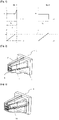
- the absorber element 1 comprises an absorption part 3 and a fixing plate 5.
- the absorption part 3 is a part whose section varies in its length. More precisely in this example, the absorption piece 3 has the shape of a truncated pyramid. The absorption piece could also have a constant section, or have for example the shape of a pyramid, a cone, or a frustoconical shape, or any other shape in which the section is not constant.
- the fixing plate 5 is injection molded with the absorption part 3. However, it could be envisaged to manufacture the fixing plate separately and to assemble it to the absorption part.
- the absorption part 3 is shown with stiffening ribs 7 and stiffening walls 9, the number, thickness and position of which can be varied, to modulate the absorption capacity of the absorption part 3.
- the absorber element 1 is shown in the picture 3 assembled with a connecting element 11 whose role is to maintain a transverse beam 19 connected to the vehicle after the impact.
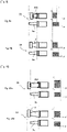
- the absorption system 13 comprises a first pair 15 of absorber elements 1, or first pair, and a second pair 17 of absorber elements 1a, or second pair.
- the absorption system 13 also comprises a transverse beam 19 which rests on the ends of high side members 21 of the body-in-white of the vehicle via the first pair 15 of absorber elements 1.
- the first pair 15 is positioned opposite the upper channel for transmitting the forces of the vehicle.
- the absorption system 13 also comprises low beams 24 positioned opposite the low force transmission path.
- the lower beams 24 are equipped with the absorber elements 1a of the second pair 17.
- the first pair 15 is positioned on the absorption system 13 at a different height than the second pair 17.
- the absorber elements 1 and 1a of the first and second pairs 15 and 17 are absorber elements according to the invention.
- the absorption parts of these absorber elements 1 and 1a according to the invention are parts whose section varies along their length. They have the shape of a truncated pyramid. These absorption parts according to the invention could also have a constant section, or have for example the shape of a pyramid, a cone, or a frustoconical shape, or any other shape in which the section is not constant. .
- the absorption piece 3 of the first pair 15 has an effective length as shown on the corresponding stroke/force plotting diagram, i.e. the distance over which the absorption piece collapses under a effort limited to calibration at Fmax.
- the effective lengths of the absorption parts 3 of the first pair 15 and 3a of the second pair 17 are substantially the same and the settings (maximum forces) are also substantially the same.
- the energy capacities (area under the curve) are substantially the same.
- the absorber elements 1 of the first pair 15 and 1a of the second pair 17 are dimensioned in the same way, that is to say they have the same calibration and the same effective length.
- This absorption system 13 comprising absorber elements 1 and 1a according to the invention, in the high way and in the low way can be used on a very light vehicle.
- the two stroke/force reading diagrams show that the effective length of the absorption part 3 of the first pair 15 is less than the effective length of the absorption part 3a of the second pair 17, and the calibration of the absorption part 3 of the first pair 15 is greater than the calibration of the absorption part 3a of the second pair 17.
- the two stroke/force reading diagrams show that the area under the curve is substantially the same for the two absorption parts 3 and 3a.
- an absorption piece 3 of an absorber element 1 of the first pair 15 has a lower effective length and a greater calibration than those of an absorption piece 3a of the second pair 17, so that a piece absorption 3 of the first pair 15 and an absorption piece 3a of the second pair 17 have a substantially identical energy capacity.
- This configuration makes it possible to integrate the volume of the beam on the upper track, or even the volume of the beam and the volume of a pedestrian shock absorber, the assembly having the same cantilever as the absorber elements in the low way. In other words, in this configuration, the entire shock functionality is contained in the same axial size, i.e. neither of the two tracks "exceeds" which would create for this track an additional overhang with respect to the congestion of the smallest lane.
- the two stroke/force reading diagrams show that the absorption part 3 of the first pair 15 and the absorption part 3a of the second pair 17 have substantially the same effective length.
- the calibration of the absorption piece 3 of the first pair 15 is greater than the calibration at the calibration of the absorption piece 3a of the second pair 17.
- the energy capacity of the absorption piece 3 of the first pair 15 is greater than the energy capacity of the absorption piece 3a of the second pair 17, as shown by the two stroke/force reading diagrams in which the area under the curve is greater for the piece of absorption 3 of the first pair 15.
- the absorption system 23 comprises a first pair 15 and a second pair 17.
- the absorption system 23 also comprises a beam transverse 19 which rests on the ends of the high longitudinal members 21 of the body in white of the vehicle via the first pair 15.
- the first pair 15 is positioned opposite the high transmission path of the vehicle stress.
- the absorption system 23 also comprises uprights 25, called hangers, making it possible to connect the lower channel for transmitting forces to the upper channel. In the lower route, the hangers 25 are equipped with the absorber elements 1a of the second pair 17.
- the effective lengths of the absorption parts 3 of the first pair 15 and 3a of the second pair 17 are substantially the same and the settings are also substantially the same.
- the energy capacities are substantially the same.
- the absorber elements 1 of the first pair 15 and 1a of the second pair 17 are dimensioned in the same way.
- This absorption system 23 comprising absorber elements 1 and 1a according to the invention, in the high way and in the low way can be used on a very light vehicle.
- This absorption system 33 is similar to that of figures 4 and 5 in that it comprises a transverse beam 19 which rests on the ends of high side members 21 of the body in white of the vehicle, and that it comprises low side members 24 positioned opposite the low path of transmission of the forces, and equipped with the absorber elements 1a of the second pair 17.
- the transverse beam 19 rests on the ends of the high side members 21 of the body-in-white via a first pair 35 of absorber elements 31.
- the absorber elements 31 of the first pair 35 are absorber elements according to the state of the art, capable of disintegrating by delamination.
- the absorption piece 313 of the first pair 35 has an effective length as shown on the corresponding stroke/force plotting diagram, i.e. the distance over which the absorption piece undergoes the maximum effort .
- this absorption piece 313 of the state of the art has a constant section; here it has the shape of a tube.
- the effective lengths of the absorption parts 313 of the first pair 35 and 3a of the second pair 17 are substantially the same and the settings (maximum forces) are also substantially the same.
- the energy capacities (area under the curve) are substantially the same.
- the absorber elements 31 of the first pair 35 and 1a of the second pair 17 are dimensioned in the same way, that is to say they have the same calibration and the same effective length.
- the two stroke/force reading diagrams show that the effective length of the absorption part 313 of the first pair 35 is less than the effective length of the absorption part 3a of the second pair 17, and the calibration of the absorption part 313 of the first pair 35 is greater than the calibration of the absorption part 3a of the second pair 17.
- the two stroke/force reading diagrams show that the area under the curve is substantially the same for the two absorption parts 313 and 3a.
- an absorption piece 313 of an absorber element 31 of the first pair 35 has a lower effective length and a greater calibration than those of an absorption piece 3a of the second pair 17, so that a piece absorption 313 of the first pair 35 and an absorption piece 3a of the second pair 17 have a substantially identical energy capacity.
- this configuration makes it possible to integrate the volume of the beam in the upper lane, or even the volume of the beam and the volume of a pedestrian shock absorber, the assembly having the same cantilever as the absorber elements in the lower lane . In other words, in this configuration, the entire shock functionality is contained in the same axial size, i.e. neither of the two tracks "exceeds" which would create for this track an additional overhang with respect to the congestion of the smallest lane.
- the two stroke/force reading diagrams show that the absorption piece 313 of the first pair 35 and the absorption piece 3a of the second pair 17 have substantially the same effective length.
- the calibration of the absorption piece 313 of the first pair 35 is greater than the calibration of the absorption piece 3a of the second pair 17.
- the energy capacity of the absorption piece 313 of the first pair 35 is greater than the energy capacity of the absorption piece 3a of the second pair 17, as shown by the two stroke/force reading diagrams in which the area under the curve is greater for the absorption piece 313 of the first pair 35.
Landscapes
- Engineering & Computer Science (AREA)
- Mechanical Engineering (AREA)
- Vibration Dampers (AREA)
- Motor Or Generator Frames (AREA)
- Insulation, Fastening Of Motor, Generator Windings (AREA)
Applications Claiming Priority (1)
| Application Number | Priority Date | Filing Date | Title |
|---|---|---|---|
| FR2014080A FR3117964A1 (fr) | 2020-12-23 | 2020-12-23 | Élément absorbeur pour véhicule automobile |
Publications (1)
| Publication Number | Publication Date |
|---|---|
| EP4019340A1 true EP4019340A1 (de) | 2022-06-29 |
Family
ID=74759076
Family Applications (1)
| Application Number | Title | Priority Date | Filing Date |
|---|---|---|---|
| EP21215879.4A Pending EP4019340A1 (de) | 2020-12-23 | 2021-12-20 | Absorbierendes element für kraftfahrzeug |
Country Status (3)
| Country | Link |
|---|---|
| EP (1) | EP4019340A1 (de) |
| CN (1) | CN114655149A (de) |
| FR (1) | FR3117964A1 (de) |
Citations (11)
| Publication number | Priority date | Publication date | Assignee | Title |
|---|---|---|---|---|
| CA2094476A1 (en) * | 1992-04-21 | 1993-10-22 | Koki Hirano | Polypropylene resin composition |
| US20090200811A1 (en) * | 2005-12-13 | 2009-08-13 | Gm Global Technology Operations, Inc. | Bumper system for a motor vehicle |
| WO2009126670A1 (en) * | 2008-04-09 | 2009-10-15 | E. I. Du Pont De Nemours And Company | Bumper energy absorbers for pedestrian safety |
| KR20100058227A (ko) * | 2008-11-24 | 2010-06-03 | 현대자동차주식회사 | 자동차 범퍼용 고유동 폴리프로필렌 수지 조성물 |
| DE102009031745A1 (de) * | 2009-07-06 | 2011-01-13 | GM Global Technology Operations, Inc., Detroit | Deformationselement, Stoßfängersystem mit einem Deformationselement und Verfahren zur Herstellung eines Deformationselementes |
| EP2540575A2 (de) * | 2011-06-30 | 2013-01-02 | Benteler Automobiltechnik GmbH | Stoßfängeranordnung für ein Kraftfahrzeug |
| US20140361562A1 (en) * | 2012-01-12 | 2014-12-11 | Thermoplast Composite Gmbh | Energy-absorbing support structure and method for the production thereof |
| EP2621759B1 (de) * | 2010-09-28 | 2016-01-20 | Tres S.r.l. | Crash box |
| FR3061465A1 (fr) | 2016-12-29 | 2018-07-06 | Compagnie Plastic Omnium | Systeme d'absorption de choc pour vehicule automobile |
| EP3738839A1 (de) * | 2019-05-17 | 2020-11-18 | Compagnie Plastic Omnium | Stossdämpfungssystem für kraftfahrzeug |
| WO2021153123A1 (ja) * | 2020-01-31 | 2021-08-05 | 東レ株式会社 | エネルギー吸収部材 |
Family Cites Families (2)
| Publication number | Priority date | Publication date | Assignee | Title |
|---|---|---|---|---|
| FR3028793B1 (fr) * | 2014-11-25 | 2017-05-05 | Plastic Omnium Cie | Procede de surmoulage sur un insert plastique et piece automobile obtenue par ce procede |
| DE102014224444B4 (de) * | 2014-11-28 | 2019-01-31 | Volkswagen Aktiengesellschaft | Aufpralldämpfende Bauteilanordnung für ein Kraftfahrzeug |
-
2020
- 2020-12-23 FR FR2014080A patent/FR3117964A1/fr active Pending
-
2021
- 2021-12-02 CN CN202111457699.0A patent/CN114655149A/zh active Pending
- 2021-12-20 EP EP21215879.4A patent/EP4019340A1/de active Pending
Patent Citations (11)
| Publication number | Priority date | Publication date | Assignee | Title |
|---|---|---|---|---|
| CA2094476A1 (en) * | 1992-04-21 | 1993-10-22 | Koki Hirano | Polypropylene resin composition |
| US20090200811A1 (en) * | 2005-12-13 | 2009-08-13 | Gm Global Technology Operations, Inc. | Bumper system for a motor vehicle |
| WO2009126670A1 (en) * | 2008-04-09 | 2009-10-15 | E. I. Du Pont De Nemours And Company | Bumper energy absorbers for pedestrian safety |
| KR20100058227A (ko) * | 2008-11-24 | 2010-06-03 | 현대자동차주식회사 | 자동차 범퍼용 고유동 폴리프로필렌 수지 조성물 |
| DE102009031745A1 (de) * | 2009-07-06 | 2011-01-13 | GM Global Technology Operations, Inc., Detroit | Deformationselement, Stoßfängersystem mit einem Deformationselement und Verfahren zur Herstellung eines Deformationselementes |
| EP2621759B1 (de) * | 2010-09-28 | 2016-01-20 | Tres S.r.l. | Crash box |
| EP2540575A2 (de) * | 2011-06-30 | 2013-01-02 | Benteler Automobiltechnik GmbH | Stoßfängeranordnung für ein Kraftfahrzeug |
| US20140361562A1 (en) * | 2012-01-12 | 2014-12-11 | Thermoplast Composite Gmbh | Energy-absorbing support structure and method for the production thereof |
| FR3061465A1 (fr) | 2016-12-29 | 2018-07-06 | Compagnie Plastic Omnium | Systeme d'absorption de choc pour vehicule automobile |
| EP3738839A1 (de) * | 2019-05-17 | 2020-11-18 | Compagnie Plastic Omnium | Stossdämpfungssystem für kraftfahrzeug |
| WO2021153123A1 (ja) * | 2020-01-31 | 2021-08-05 | 東レ株式会社 | エネルギー吸収部材 |
Also Published As
| Publication number | Publication date |
|---|---|
| CN114655149A (zh) | 2022-06-24 |
| FR3117964A1 (fr) | 2022-06-24 |
Similar Documents
| Publication | Publication Date | Title |
|---|---|---|
| EP1631752B1 (de) | Kraftfahrzeugbauteil zum dämpfen von stössen durch plastische verformung | |
| EP2934953B1 (de) | Stossdämpfungsvorrichtung für die vorder- oder hinterstruktur eines fahrzeugs | |
| EP2643192B1 (de) | Energieabsorptionsvorrichtung mit in kunststoff eingebetteten fasern und zugehörige vorderseite | |
| FR2936469A1 (fr) | Structure avant de vehicule automobile et vehicule automobile comportant une telle structure avant | |
| EP3844050A1 (de) | Fahrzeug mit einer intelligenten frontalaufpralldämpfungsvorrichtung | |
| FR2984839A1 (fr) | Interface de fixation d'un plancher pour fixation d'un berceau moteur de vehicule et vehicule presentant une telle interface. | |
| FR3117964A1 (fr) | Élément absorbeur pour véhicule automobile | |
| WO2012146851A1 (fr) | Capot de vehicule avec doublure amortissante pour choc pieton | |
| FR2897812A1 (fr) | Vehicule comprenant un support muni d'une butee absorbant l'energie d'un choc | |
| FR3047455A1 (fr) | Vehicule avec glissiere de renfort en cas de choc frontal avant a faible chevauchement | |
| EP3277543B1 (de) | Fahrzeug mit leichtbaustruktur mit zwei blastungswege | |
| EP2210799B1 (de) | Verkleidungseinheit unter dem Motor für eine Frontstruktur eines Kraftfahrzeugs | |
| WO2020174161A1 (fr) | Sous-ensemble de structure de pare-chocs comprenant un element amortisseur associe a un capteur d'impact | |
| FR3120834A1 (fr) | Absorbeur de chocs en mousse pour véhicule automobile | |
| FR3081423A1 (fr) | Vehicule avec dispositif d’absorption a surface d’impact augmentant durant un choc. | |
| FR3072926B1 (fr) | Vehicule comprenant un dispositif de pare-chocs avec un ecran deployable | |
| EP3009305B1 (de) | Automobil-stossfänger | |
| FR2876646A1 (fr) | Poutre tubulaire de structure automobile renforcee pour amelioration du comportement au choc | |
| FR3071808B1 (fr) | Pied avant renforce de vehicule | |
| EP3320223B1 (de) | Stossfängermodul für ein kraftfahrzeug | |
| EP3245108B1 (de) | Energieabsorber element für stossfänger eines fahrzeuges | |
| FR3088268A1 (fr) | Vehicule automobile comprenant un systeme de renfort reliant le dispositif de pare-chocs avant aux ailes avant et/ou aux pare-boue | |
| FR3052720A1 (fr) | Vehicule dont le train arriere comprend au moins un dispositif d’entretoisement | |
| FR3150485A1 (fr) | Dispositif absorbeur d’énergie | |
| EP1997694A1 (de) | Fahrzeug, das ein Gestell umfasst, das mit einem Aufprallenergieabsorber ausgerüstet ist |
Legal Events
| Date | Code | Title | Description |
|---|---|---|---|
| PUAI | Public reference made under article 153(3) epc to a published international application that has entered the european phase |
Free format text: ORIGINAL CODE: 0009012 |
|
| STAA | Information on the status of an ep patent application or granted ep patent |
Free format text: STATUS: THE APPLICATION HAS BEEN PUBLISHED |
|
| AK | Designated contracting states |
Kind code of ref document: A1 Designated state(s): AL AT BE BG CH CY CZ DE DK EE ES FI FR GB GR HR HU IE IS IT LI LT LU LV MC MK MT NL NO PL PT RO RS SE SI SK SM TR |
|
| STAA | Information on the status of an ep patent application or granted ep patent |
Free format text: STATUS: REQUEST FOR EXAMINATION WAS MADE |
|
| 17P | Request for examination filed |
Effective date: 20221024 |
|
| RBV | Designated contracting states (corrected) |
Designated state(s): AL AT BE BG CH CY CZ DE DK EE ES FI FR GB GR HR HU IE IS IT LI LT LU LV MC MK MT NL NO PL PT RO RS SE SI SK SM TR |
|
| P01 | Opt-out of the competence of the unified patent court (upc) registered |
Effective date: 20230517 |
|
| STAA | Information on the status of an ep patent application or granted ep patent |
Free format text: STATUS: EXAMINATION IS IN PROGRESS |
|
| 17Q | First examination report despatched |
Effective date: 20240108 |
|
| RAP3 | Party data changed (applicant data changed or rights of an application transferred) |
Owner name: OPMOBILITY SE |
|
| RAP3 | Party data changed (applicant data changed or rights of an application transferred) |
Owner name: OPMOBILITY SE |