EP4019717B1 - Schliesszylinder mit verbesserter sicherheit - Google Patents
Schliesszylinder mit verbesserter sicherheit Download PDFInfo
- Publication number
- EP4019717B1 EP4019717B1 EP20216498.4A EP20216498A EP4019717B1 EP 4019717 B1 EP4019717 B1 EP 4019717B1 EP 20216498 A EP20216498 A EP 20216498A EP 4019717 B1 EP4019717 B1 EP 4019717B1
- Authority
- EP
- European Patent Office
- Prior art keywords
- abutment
- rotor
- counter
- lock cylinder
- key
- Prior art date
- Legal status (The legal status is an assumption and is not a legal conclusion. Google has not performed a legal analysis and makes no representation as to the accuracy of the status listed.)
- Active
Links
Images




Classifications
-
- E—FIXED CONSTRUCTIONS
- E05—LOCKS; KEYS; WINDOW OR DOOR FITTINGS; SAFES
- E05B—LOCKS; ACCESSORIES THEREFOR; HANDCUFFS
- E05B27/00—Cylinder locks or other locks with tumbler pins or balls that are set by pushing the key in
- E05B27/0042—Cylinder locks or other locks with tumbler pins or balls that are set by pushing the key in with additional key identifying function, e.g. with use of additional key operated rotor-blocking elements, not of split pin tumbler type
-
- E—FIXED CONSTRUCTIONS
- E05—LOCKS; KEYS; WINDOW OR DOOR FITTINGS; SAFES
- E05B—LOCKS; ACCESSORIES THEREFOR; HANDCUFFS
- E05B27/00—Cylinder locks or other locks with tumbler pins or balls that are set by pushing the key in
- E05B27/0057—Cylinder locks or other locks with tumbler pins or balls that are set by pushing the key in with increased picking resistance
- E05B27/006—Cylinder locks or other locks with tumbler pins or balls that are set by pushing the key in with increased picking resistance whereby a small rotation without the correct key blocks further rotation of the rotor
Definitions
- the present invention relates to a lock cylinder for use with a flat key, with a movable counter-abutment as a second security means.
- Lock cylinder has a set of housings aligned in a vertical axis; and each housing containing a pin spring, a body pin, and a rotor pin partly project into a keyway of the rotor; the pins being urged by the spring towards the keyway and ensuring, in the absence of the flat key, blocking of the rotor with respect to the cylinder body.
- a prior art publication in the technical field of the present invention may be referred to as US2016145896 (A1 ) among others, the document disclosing a locking system comprises a lock cylinder which has a cylinder housing, a cylinder core rotatably supported in the cylinder housing, and having a keyway, and has a plurality of tumblers which partly project into the keyway, and an abutment section which is formed at the key shaft between the key bow and the shaft profile.
- the primary object of the present invention is to provide an alternative lock cylinder for a flat key in which the pins play their traditional role with improved security.
- the present invention proposes a lock cylinder for use with a flat key having an abutment section on a key shaft, comprising: a cylinder body having a central longitudinal axis; a rotor having a keyway for receiving the key, rotatable within the cylinder body; a set of housings aligned in a vertical axis relative to the central longitudinal axis; and each housing containing a pin spring, a body pin, and a rotor pin partly project into the keyway; the pins being urged by the spring towards the keyway and ensuring, in the absence of the flat key, blocking of the rotor with respect to the cylinder body.
- the lock cylinder further comprises: a spring-biased movable counter-abutment guided in a hollowed portion formed on the rotor wherein the counter-abutment is movable between a release position in which a corresponding body pin can pass and continue its rotation via the counter-abutment and a lock position in which the corresponding body pin reaches the hollowed portion where the further rotation of the rotor is blocked.
- the movable counter-abutment is arranged and configured such that, when the suitable flat key is not inserted, the counter-abutment stays in the lock position under the spring force, while on an introduction of the key into the keyway, the abutment section pushes the movable counter-abutment to the released position to correspond to the body pin for allowing the rotation of the rotor.
- the invention provides a spring biased counter-abutment, which stays in the lock position under the spring force when the suitable flat key is not inserted.
- the arrangement has a deterrent feature against malicious acts intended to be done in a short time.
- the hollowed portion of the rotor has at least one guiding slot in which a leg of the counter-abutment is guided. Thus, the movement of the counter-abutment is properly aligned.
- the guiding slot extends on the longitudinal axis of the rotor with an enlarged engagement portion wherein one of the body pins engages with said engagement portion of the guiding slot and blocks the rotation of the rotor when the counter-abutment is in the lock position.
- the counter-abutment and the engagement portion of the guiding slot are arranged and configured such that, on an introduction of the key into the keyway, the counter-abutment is guided onto the engagement portion for corresponding to one of the body pins thereby aligning said body pin with others.
- the rotor is provided with two similarly shaped guiding slots on the rotor with a predetermined distance from each other, and the counter-abutment has two similarly shaped legs, where each leg is guided on said guiding slots, respectively.
- the invention provides the same security according to all kinds of opening directions.
- the hollowed portion has at least one elongated cavity in which an arm of the counter-abutment is linearly guided.
- the counter-abutment is biased with a spring in the hollowed portion wherein the spring is placed between the counter-abutment and a planar abutment surface formed on the rotor.
- the counter-abutment has an arc-shaped upper surface that corresponds to the body pin when the rotor is rotated and moves one of the body pins to align with the other body pins.
- the cylinder body has a first cylinder half and a second cylinder half, and the rotor is placed within the first cylinder half.
- any side of the lock cylinder can be used.
- the key actuated counter-abutment is guided on a distal end of the rotor relative to the inlet of the keyway.
- the unauthorized person cannot reach and trigger the counter-abutment.
- the present invention also proposes a locking system for use in a door, comprising:
- the abutment section of the flat key is a raised portion that extends perpendicularly from the key shaft relative to the longitudinal axis of the flat key.
- the keyway of the rotor has an open traverse upper end for insertion of the key shaft.
- the picklock or the like is simply inserted into the keyway of the rotor and turned clockwise with medium torque.
- each of the pins is slowly forced down with up and down movement until they stop, thus binding the body pins behind the shear line of the lock cylinder.
- the shear plane is clear and the lock cylinder opens.
- the proposed counter-abutment partly closes the open traverse upper end of the keyway, therefore, the unauthorized person using picklock will not be able to make up and down movement. This also gives additional security to the lock cylinder.
- the present invention proposes a lock cylinder (10) for use with a flat key (40) having an abutment section (41) on a key shaft (42), comprising: a cylinder body (30) having a central longitudinal axis (X); a rotor (20) having a keyway (11) for receiving the flat key (40), rotatable within the cylinder body (30); a set of housings aligned in a vertical axis (Y) relative to the central longitudinal axis (X); and each housing containing a pin spring (33), a body pin (31), and a rotor pin (32) partly project into the keyway (11); the pins being urged by the spring towards the keyway (11) and ensuring, in the absence of the flat key (40), blocking of the rotor (20) with respect to the cylinder body (30).
- the lock cylinder (10) further comprises: a spring-biased movable counter-abutment (14) guided in a hollowed portion (16) formed on the rotor (20) wherein the counter-abutment (14) is movable between a release position and a lock position in the hollowed portion (16).
- the movable counter-abutment (14) is arranged and configured such that, on an introduction of the key (40) into the keyway (11), the abutment section (41) pushes the movable counter-abutment (14) to the released position to correspond to one of the body pins (31) for allowing the rotation of the rotor (20).
- the counter abutment (14) is arranged to be pushed by the abutment section (41) of the flat key (40).
- the counter-abutment (14) is movable between a release position in which the counter-abutment (14) authorizes rotation of the rotor (20) and a lock position in which the counter-abutment (14) prevents the rotation of the rotor (20).
- Said hollowed portion (16) is formed on the rotor and a volume is created in which the spring-biased movable counter-abutment (14) is guided.
- the hollowed portion (16) of the rotor (20) has at least one guiding slot (13) in which a leg (18) of the counter-abutment (14) is guided.
- the rotor (20) is provided with two similarly shaped guiding slots (13) on the rotor (20) with a predetermined distance from each other and the counter-abutment (14) has two similar shaped legs (18), where each leg (18) is guided on said guiding slots (13), respectively.
- the rotor (20) is provided with two similarly shaped guiding slots (13) on the rotor (20) with a predetermined distance from each other and the counter-abutment (14) has two similar shaped legs (18), where each leg (18) is guided on said guiding slots (13), respectively.
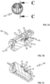
- said guiding slots (13) are formed on the hollowed portion (16). Moreover, the guiding slot (13) extends on the longitudinal axis of the rotor (20) with an enlarged engagement portion (13a) wherein one of the body pins (31) engages with the engagement portion (13a) of the guiding slot (13) and blocks the rotation of the rotor (20) when the counter-abutment (14) is in the lock position (see Fig. 10b ).
- the body pins (31) disclosed in the invention are conventional pins for use in the lock cylinder (10) with a tapered end portion.
- the rotor (20) is arranged with vicinity formed by the hollowed portion (16) into which one of the body pins (31) engages for preventing rotation of the rotor (20).
- the counter-abutment (14) and the engagement portion (13a) of the guiding slot (13) are arranged and configured such that, on an introduction of the key (40) into the keyway (11), the counter-abutment (14) is guided onto the engagement portion (13a) for corresponding to one of the body pins (31) thereby aligning said body pin (31) with others.
- the hollowed portion (16) has at least one elongated cavity (22) in which an arm (17) of the counter-abutment (14) is linearly guided.
- the hollowed portion (16) has two similarly shaped elongated cavities (22) for guiding two arms (17) of the counter-abutment (14).
- the elongated cavity (22) has a rectangular cross-section and can vary with respect to the shape of the arm (17).
- the counter-abutment (14) is a separate one-piece with at least one arm (17), at least one leg (18), a pushing surface (21) to be pushed by the abutment section of the key, and an arc-shaped upper surface for corresponding to the body pin (31).
- the movable counter-abutment (14) are always biased with a spring (15) in the hollowed portion (16) wherein the spring (15) is placed between the counter-abutment (14) and a planar abutment surface (23) formed on the rotor (20).
- two springs (15) can be used for pushing against the legs (18) of the counter-abutment (14).
- Each leg (18) has a spring protrusion (24) for holding the spring (15) properly in its housing.
- One end of the spring (15) pushes the leg (18) and the other end of the spring (15) abuts the planar abutment surface (23) of the rotor (20).
- the planar abutment surface (23) is an extension of an upper-end section (12) of the hollowed portion (16).
- the springs (15) are placed under the guide slots (13), respectively, in order to prevent any external intervention.
- the counter-abutment (14) is movable between a release position and a lock position in the hollowed portion (16).
- the counter-abutment (14) stays in the lock position under the spring force. In this state, as a second security means, even if the all body pins (31) and rotor pins (32) are aligned with a tool and the rotor (20) is rotated, one of the body pins (31) will engage with the corresponding the engagement portion (13a) of the guiding slot (13), as seen in fig. 10b .
- Said counter-abutment (14) When the authorized user inserts the corresponding key (20), the counter-abutment (14) is pushed to the release position wherein the counter-abutment (14) closes the engagement portion (13a) of the guiding slot (13) and said body pin (31) rotates over the counter-abutment (14).
- Said counter-abutment (14) has an arc-shaped upper surface (25) that corresponds to the body pin (31) when the rotor (20) is rotated and aligns the body pin (31) with other body pins (31).
- Said arc-shaped upper surface (25) are partly similar to the upper periphery of the rotor (20).
- Said counter-abutment (14) is key actuated and is guided on a distal end of the rotor (20) relative to the inlet of the keyway (11). So unauthorized person may not reach and trigger the counter-abutment (14).
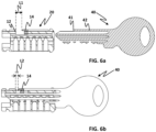
- the counter-abutment (14) is in the first position and has a predetermined first distance which is shown as "L1" in fig. 6a .
- L1 refers to the distance in between the upper-end section (12) and the counter-abutment (14).
- L2 refers to the distance in between the upper-end section (12) and the counter-abutment (14). Said “L2" is shorter than the "L1” and can be arranged to the corresponding body (31).
- the present invention also proposes a locking system, comprising: a lock cylinder (10) as explained above, and a flat key (40) for use with a rotor (20) of the lock cylinder (10).
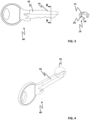
- Said flat key (40) has a key shaft (42) having longitudinal grooves extending a majority of the length of the key shaft (42).
- the flat key (40) has an abutment section (41) on the key shaft (42) for moving the counter-abutment (14) in between a release position and a lock position on the rotor (20).
- the abutment section (41) of the flat key (40) can be a raised portion that extends perpendicularly from the key shaft (42) relative to the longitudinal axis of the flat key (40).
- the pins work in a traditional way and one of the body pins (31) functions as a second security means.
- one of the body pins (31) is selected for engagement. For instance, referring to the fig. 10b , fifth-row body pin (31) matches with the engagement portion (13a).
- the number of the body pin (31) and the order of the matching body pin(s) (31) may vary.
- the cylinder body (30) mainly has a first cylinder half (34a) and a second cylinder half (34b), and the rotor (20) is placed within the first cylinder half (34a).
- a conventional type of lock cylinder can be used.
Landscapes
- Lock And Its Accessories (AREA)
Claims (12)
- Schließzylinder (10) zum Verwenden mit einem Flachschlüssel (40), der einen Anschlagabschnitt (41) an einem Schlüsselschaft (42) aufweist, aufweisend:einen Zylinderkörper (30) mit einer zentralen Längsachse (X);einen Drehzylinder (20) mit einer Schlüsselnut (11) zur Aufnahme des Schlüssels (40), der in dem Zylinderkörper (30) drehbar ist;einen Satz von Gehäusen, die in einer vertikalen Achse (Y) bezüglich der zentralen Längsachse (X) ausgerichtet sind; und wobei jedes Gehäuse eine Stiftfeder (33), einen Körperstift (31) und einen Drehzylinderstift (32) enthält, die teilweise in die Schlüsselnut (11) ragen; wobei die Stifte durch die Feder in Richtung der Schlüsselnut (11) gedrückt werden und in Abwesenheit des Flachschlüssels (40) ein Blockieren des Drehzylinders (20) in Bezug auf den Zylinderkörper (30) gewährleisten,wobei der Schließzylinder (10) ferner aufweist:
ein federvorgespanntes, bewegliches Gegenlager (14), das in einem am Drehzylinder (20) ausgebildeten hohlen Abschnitt (16) geführt ist, wobei das Gegenlager (14) beweglich zwischen einer Freigabeposition, in der ein entsprechender Körperstift (31) passieren kann und seine Drehung über das Gegenlager (14) fortsetzen kann, und einer Sperrposition ist, in der der entsprechende Körperstift (31) den ausgehöhlten Abschnitt (16) erreicht, wobei die weitere Drehung des Drehzylinders (20) blockiert ist, und
wobei das bewegliche Gegenlager (14) so angeordnet und ausgebildet ist, dass, wenn der passende Flachschlüssel (40) nicht eingesteckt ist, das Gegenlager (14) unter der Federkraft in der Sperrstellung verbleibt, während bei einer Einführung des Flachschlüssels (40) in die Schlüsselnut (11) der Anschlagabschnitt (41) das beweglichen Gegenlager (14) in die Freigabestellung schiebt, um dem Körperstift (31) zu entsprechen, um die Drehung des Drehzylinders (20) zu ermöglichen. - Schließzylinder (10) nach Anspruch 1, wobei der ausgehöhlte Teil (16) des Drehzylinders (20) mindestens einen Führungsschlitz (13) aufweist, in dem ein Schenkel (18) des Gegenlagers (14) geführt wird.
- Schließzylinder (10) nach Anspruch 2, wobei der Führungsschlitz (13) sich in der Längsachse des Drehzylinder (20) mit einem vergrößerten Eingriffsabschnitt (13a) erstreckt, wobei einer der Körperstifte (31) in den Eingriffsabschnitt (13a) des Führungsschlitzes (13) eingreift und die Drehung des Drehzylinders (20) blockiert, wenn sich das Gegenlager (14) in der Verriegelungsposition befindet.
- Schließzylinder (10) nach Anspruch 3, wobei der Gegenlager (14) und der Eingriffsabschnitt (13a) des Führungsschlitzes (13) so angeordnet und ausgebildet sind, dass bei einem Einführen des Schlüssels (40) in die Schlüsselnut (11) das Gegenlager (14) auf den Eingriffsabschnitt (13a) geführt wird, um einem der Körperstifte (31) zu entsprechen, damit der Körperstift (31) mit den anderen sich ausrichtet.
- Schließzylinder (10) nach irgendeinem der Ansprüche 2 bis 4, wobei der Drehzylinder (20) mit zwei ähnlich geformten Führungsschlitzen (13) auf dem Drehzylinder (20) versehen ist, die einen vorbestimmten Abstand voneinander haben, und das Gegenlager (14) zwei ähnlich geformte Schenkel (18) aufweist, wobei jeder Schenkel (18) an den jeweiligen Führungsschlitzen (13) geführt wird.
- Schließzylinder (10) nach irgendeinem der vorhergehenden Ansprüche, wobei der ausgehöhlte Abschnitt (16) mindestens einen länglichen Hohlraum (22) aufweist, in dem ein Arm (17) des Gegenlagers (14) linear geführt ist.
- Schließzylinder (10) nach irgendeinem der vorhergehenden Ansprüche, wobei das Gegenlager (14) mit einer Feder (15) in dem ausgehöhlten Abschnitt (16) vorgespannt ist, wobei die Feder (15) zwischen dem Gegenlager (14) und einer an dem Drehzylinder (20) ausgebildeten ebenen Anlagefläche (23) angeordnet ist.
- Schließzylinder (10) nach irgendeinem der vorhergehenden Ansprüche, wobei das Gegenlager (14) eine bogenförmige Oberseite (25) aufweist, die dem Körperstift (31) entspricht, wenn der Drehzylinder (20) gedreht wird und einen der Körperstifte (31) bewegt, um sich nach den anderen Körperstiften (31) auszurichtet.
- Schließzylinder (10) nach irgendeinem der vorhergehenden Ansprüche, wobei der Zylinderkörper (30) eine erste Zylinderhälfte (34a) und eine zweite Zylinderhälfte (34b) aufweist, und der Drehzylinder (20) innerhalb der ersten Zylinderhälfte (34a) angeordnet ist.
- Schließzylinder (10) nach irgendeinem der vorhergehenden Ansprüche, wobei das schlüsselbetätigte Gegenlager (14) an einem Distalende des Drehzylinders (20) bezüglich des Eingangs der Schlüsselnut (11) geführt ist.
- Schließsystem zur Verwendung in einer Tür, aufweisend:- einem Schließzylinder (10) nach irgendeinem der vorhergehenden Ansprüche;
und- einem Flachschlüssel (40) zur Verwendung mit einem Drehzylinder (20) des Schließzylinders (10), wobei der Flachschlüssel (40) einen Schlüsselschaft (42) mit Längsnuten aufweist, die sich über einen Großteil der Länge des Schlüsselschafts (42) erstrecken, wobei der Flachschlüssel (40) einen Anschlagabschnitt (41) an dem Schlüsselschaft (42) hat zum Bewegen des Gegenlagers (14) zwischen einer Freigabe- und einer Sperrposition an dem Drehzylinder (20). - Verriegelungssystem nach Anspruch 11, wobei der Anschlagabschnitt (41) des Flachschlüssels (40) ein erhabener Abschnitt ist, der sich senkrecht vom Schlüsselschaft (42) bezüglich der Längsachse des Flachschlüssels (40) erstreckt.
Priority Applications (1)
| Application Number | Priority Date | Filing Date | Title |
|---|---|---|---|
| EP20216498.4A EP4019717B1 (de) | 2020-12-22 | 2020-12-22 | Schliesszylinder mit verbesserter sicherheit |
Applications Claiming Priority (1)
| Application Number | Priority Date | Filing Date | Title |
|---|---|---|---|
| EP20216498.4A EP4019717B1 (de) | 2020-12-22 | 2020-12-22 | Schliesszylinder mit verbesserter sicherheit |
Publications (2)
| Publication Number | Publication Date |
|---|---|
| EP4019717A1 EP4019717A1 (de) | 2022-06-29 |
| EP4019717B1 true EP4019717B1 (de) | 2023-05-10 |
Family
ID=73856818
Family Applications (1)
| Application Number | Title | Priority Date | Filing Date |
|---|---|---|---|
| EP20216498.4A Active EP4019717B1 (de) | 2020-12-22 | 2020-12-22 | Schliesszylinder mit verbesserter sicherheit |
Country Status (1)
| Country | Link |
|---|---|
| EP (1) | EP4019717B1 (de) |
Citations (3)
| Publication number | Priority date | Publication date | Assignee | Title |
|---|---|---|---|---|
| DE19604594C1 (de) * | 1996-02-08 | 1997-02-20 | August Knapp Schliestechnik Gm | Kombination eines Schließzylinders und eines Flachschlüssels für Waren- und Spielautomaten, Geldwechselautomaten, Fahrkartenautomaten und dergleichen, mit Stiftzuhaltungen |
| DE19939734B4 (de) * | 1999-08-21 | 2007-04-05 | Wilka Schließtechnik GmbH | Aus Schließzylinder und Schlüssel bestehende Schließvorrichtung |
| US20100206026A1 (en) * | 2009-02-18 | 2010-08-19 | Bo Widen | Profile key with local recess |
Family Cites Families (7)
| Publication number | Priority date | Publication date | Assignee | Title |
|---|---|---|---|---|
| FR2388966A1 (fr) * | 1977-04-27 | 1978-11-24 | Gruslin Philippe | Perfectionnement aux serrures a barillet |
| US4341102A (en) * | 1978-06-26 | 1982-07-27 | Ku Chung C | Construction for a cylinder lock and key |
| DE10031972A1 (de) * | 2000-06-30 | 2002-01-10 | Winkhaus Fa August | Schlüssel für einen Profilschliesszylinder und Profilschliesszylinder |
| US7028517B2 (en) * | 2003-07-09 | 2006-04-18 | Kaba High Security Locks Corporation | Cylinder lock with programmable keyway |
| FR2988760B1 (fr) * | 2012-03-28 | 2014-03-21 | Assa Abloy Aube Anjou | Cylindre de securite a embrayeurs, et cle correspondante |
| DE102014116376A1 (de) | 2014-11-10 | 2016-05-12 | ABUS August Bremicker Söhne KG | Schließsystem, Schlüssel und Schlüsselrohling |
| FR3074827B1 (fr) * | 2017-12-13 | 2021-02-12 | Etablissements Thirard | Cle et cylindre pour serrure de surete |
-
2020
- 2020-12-22 EP EP20216498.4A patent/EP4019717B1/de active Active
Patent Citations (3)
| Publication number | Priority date | Publication date | Assignee | Title |
|---|---|---|---|---|
| DE19604594C1 (de) * | 1996-02-08 | 1997-02-20 | August Knapp Schliestechnik Gm | Kombination eines Schließzylinders und eines Flachschlüssels für Waren- und Spielautomaten, Geldwechselautomaten, Fahrkartenautomaten und dergleichen, mit Stiftzuhaltungen |
| DE19939734B4 (de) * | 1999-08-21 | 2007-04-05 | Wilka Schließtechnik GmbH | Aus Schließzylinder und Schlüssel bestehende Schließvorrichtung |
| US20100206026A1 (en) * | 2009-02-18 | 2010-08-19 | Bo Widen | Profile key with local recess |
Also Published As
| Publication number | Publication date |
|---|---|
| EP4019717A1 (de) | 2022-06-29 |
Similar Documents
| Publication | Publication Date | Title |
|---|---|---|
| EP1236849B1 (de) | Schlüssel für ein Zylinderschloss | |
| KR100857572B1 (ko) | 사이드 바아 제어를 구비하는 회전 핀 텀블러 사이드 바아록 | |
| USRE39364E1 (en) | Cylinder lock and key | |
| US10745937B2 (en) | Modular lock plug | |
| EP2126256B1 (de) | Schliesszylinder und zugehöriger schlüssel und schlüsselrohling dafür | |
| EP2899337B1 (de) | Sperrsystem | |
| EP2173954A1 (de) | Hierarchisches zylinderschlosssystem | |
| US20170254113A1 (en) | Cylinder lock | |
| TWI847265B (zh) | 鑰匙、鎖芯、解鎖方法以及形成鑰匙的方法 | |
| JP2020533501A (ja) | ロック装置 | |
| US20060230797A1 (en) | Key core | |
| AU2016429210B2 (en) | Security lock | |
| EP4019717A1 (de) | Schliesszylinder mit verbesserter sicherheit | |
| EP3103944B1 (de) | Schlüssel mit einem drehbaren element und einem schloss | |
| CN113445823B (zh) | 锁芯 | |
| GB2372284A (en) | Cylinder lock having a key retaining catch bar | |
| EP1355023A1 (de) | Schliesszylinder und zugehöriger Schlüssel | |
| US7793528B2 (en) | Key-operated mechanical lock | |
| WO2016179631A1 (en) | Lock and key therefor | |
| EP1366256B1 (de) | Drehstiftzuhaltungsschloss mit seitlichen riegel und steuerung für seitlichen riegel | |
| EP3872283B1 (de) | Verriegelungssystem und schloss | |
| EP4158140B1 (de) | Schloss und zugehöriger schlüssel | |
| AU2013204413A1 (en) | Lock system | |
| AU2013204530B1 (en) | Lock Structure | |
| WO2010130994A1 (en) | Improvements to key-operated pin tumbler locks |
Legal Events
| Date | Code | Title | Description |
|---|---|---|---|
| PUAI | Public reference made under article 153(3) epc to a published international application that has entered the european phase |
Free format text: ORIGINAL CODE: 0009012 |
|
| STAA | Information on the status of an ep patent application or granted ep patent |
Free format text: STATUS: THE APPLICATION HAS BEEN PUBLISHED |
|
| AK | Designated contracting states |
Kind code of ref document: A1 Designated state(s): AL AT BE BG CH CY CZ DE DK EE ES FI FR GB GR HR HU IE IS IT LI LT LU LV MC MK MT NL NO PL PT RO RS SE SI SK SM TR |
|
| STAA | Information on the status of an ep patent application or granted ep patent |
Free format text: STATUS: REQUEST FOR EXAMINATION WAS MADE |
|
| 17P | Request for examination filed |
Effective date: 20221227 |
|
| RBV | Designated contracting states (corrected) |
Designated state(s): AL AT BE BG CH CY CZ DE DK EE ES FI FR GB GR HR HU IE IS IT LI LT LU LV MC MK MT NL NO PL PT RO RS SE SI SK SM TR |
|
| GRAP | Despatch of communication of intention to grant a patent |
Free format text: ORIGINAL CODE: EPIDOSNIGR1 |
|
| STAA | Information on the status of an ep patent application or granted ep patent |
Free format text: STATUS: GRANT OF PATENT IS INTENDED |
|
| GRAS | Grant fee paid |
Free format text: ORIGINAL CODE: EPIDOSNIGR3 |
|
| INTG | Intention to grant announced |
Effective date: 20230309 |
|
| GRAA | (expected) grant |
Free format text: ORIGINAL CODE: 0009210 |
|
| STAA | Information on the status of an ep patent application or granted ep patent |
Free format text: STATUS: THE PATENT HAS BEEN GRANTED |
|
| AK | Designated contracting states |
Kind code of ref document: B1 Designated state(s): AL AT BE BG CH CY CZ DE DK EE ES FI FR GB GR HR HU IE IS IT LI LT LU LV MC MK MT NL NO PL PT RO RS SE SI SK SM TR |
|
| REG | Reference to a national code |
Ref country code: GB Ref legal event code: FG4D |
|
| REG | Reference to a national code |
Ref country code: AT Ref legal event code: REF Ref document number: 1566823 Country of ref document: AT Kind code of ref document: T Effective date: 20230515 Ref country code: CH Ref legal event code: EP |
|
| REG | Reference to a national code |
Ref country code: DE Ref legal event code: R096 Ref document number: 602020010720 Country of ref document: DE |
|
| REG | Reference to a national code |
Ref country code: IE Ref legal event code: FG4D |
|
| P01 | Opt-out of the competence of the unified patent court (upc) registered |
Effective date: 20230611 |
|
| REG | Reference to a national code |
Ref country code: NL Ref legal event code: FP |
|
| REG | Reference to a national code |
Ref country code: LT Ref legal event code: MG9D |
|
| REG | Reference to a national code |
Ref country code: AT Ref legal event code: MK05 Ref document number: 1566823 Country of ref document: AT Kind code of ref document: T Effective date: 20230510 |
|
| PG25 | Lapsed in a contracting state [announced via postgrant information from national office to epo] |
Ref country code: SE Free format text: LAPSE BECAUSE OF FAILURE TO SUBMIT A TRANSLATION OF THE DESCRIPTION OR TO PAY THE FEE WITHIN THE PRESCRIBED TIME-LIMIT Effective date: 20230510 Ref country code: PT Free format text: LAPSE BECAUSE OF FAILURE TO SUBMIT A TRANSLATION OF THE DESCRIPTION OR TO PAY THE FEE WITHIN THE PRESCRIBED TIME-LIMIT Effective date: 20230911 Ref country code: NO Free format text: LAPSE BECAUSE OF FAILURE TO SUBMIT A TRANSLATION OF THE DESCRIPTION OR TO PAY THE FEE WITHIN THE PRESCRIBED TIME-LIMIT Effective date: 20230810 Ref country code: ES Free format text: LAPSE BECAUSE OF FAILURE TO SUBMIT A TRANSLATION OF THE DESCRIPTION OR TO PAY THE FEE WITHIN THE PRESCRIBED TIME-LIMIT Effective date: 20230510 Ref country code: AT Free format text: LAPSE BECAUSE OF FAILURE TO SUBMIT A TRANSLATION OF THE DESCRIPTION OR TO PAY THE FEE WITHIN THE PRESCRIBED TIME-LIMIT Effective date: 20230510 |
|
| PG25 | Lapsed in a contracting state [announced via postgrant information from national office to epo] |
Ref country code: RS Free format text: LAPSE BECAUSE OF FAILURE TO SUBMIT A TRANSLATION OF THE DESCRIPTION OR TO PAY THE FEE WITHIN THE PRESCRIBED TIME-LIMIT Effective date: 20230510 Ref country code: PL Free format text: LAPSE BECAUSE OF FAILURE TO SUBMIT A TRANSLATION OF THE DESCRIPTION OR TO PAY THE FEE WITHIN THE PRESCRIBED TIME-LIMIT Effective date: 20230510 Ref country code: LV Free format text: LAPSE BECAUSE OF FAILURE TO SUBMIT A TRANSLATION OF THE DESCRIPTION OR TO PAY THE FEE WITHIN THE PRESCRIBED TIME-LIMIT Effective date: 20230510 Ref country code: LT Free format text: LAPSE BECAUSE OF FAILURE TO SUBMIT A TRANSLATION OF THE DESCRIPTION OR TO PAY THE FEE WITHIN THE PRESCRIBED TIME-LIMIT Effective date: 20230510 Ref country code: IS Free format text: LAPSE BECAUSE OF FAILURE TO SUBMIT A TRANSLATION OF THE DESCRIPTION OR TO PAY THE FEE WITHIN THE PRESCRIBED TIME-LIMIT Effective date: 20230910 Ref country code: HR Free format text: LAPSE BECAUSE OF FAILURE TO SUBMIT A TRANSLATION OF THE DESCRIPTION OR TO PAY THE FEE WITHIN THE PRESCRIBED TIME-LIMIT Effective date: 20230510 Ref country code: GR Free format text: LAPSE BECAUSE OF FAILURE TO SUBMIT A TRANSLATION OF THE DESCRIPTION OR TO PAY THE FEE WITHIN THE PRESCRIBED TIME-LIMIT Effective date: 20230811 |
|
| PG25 | Lapsed in a contracting state [announced via postgrant information from national office to epo] |
Ref country code: FI Free format text: LAPSE BECAUSE OF FAILURE TO SUBMIT A TRANSLATION OF THE DESCRIPTION OR TO PAY THE FEE WITHIN THE PRESCRIBED TIME-LIMIT Effective date: 20230510 |
|
| PG25 | Lapsed in a contracting state [announced via postgrant information from national office to epo] |
Ref country code: SK Free format text: LAPSE BECAUSE OF FAILURE TO SUBMIT A TRANSLATION OF THE DESCRIPTION OR TO PAY THE FEE WITHIN THE PRESCRIBED TIME-LIMIT Effective date: 20230510 |
|
| PG25 | Lapsed in a contracting state [announced via postgrant information from national office to epo] |
Ref country code: SM Free format text: LAPSE BECAUSE OF FAILURE TO SUBMIT A TRANSLATION OF THE DESCRIPTION OR TO PAY THE FEE WITHIN THE PRESCRIBED TIME-LIMIT Effective date: 20230510 Ref country code: SK Free format text: LAPSE BECAUSE OF FAILURE TO SUBMIT A TRANSLATION OF THE DESCRIPTION OR TO PAY THE FEE WITHIN THE PRESCRIBED TIME-LIMIT Effective date: 20230510 Ref country code: RO Free format text: LAPSE BECAUSE OF FAILURE TO SUBMIT A TRANSLATION OF THE DESCRIPTION OR TO PAY THE FEE WITHIN THE PRESCRIBED TIME-LIMIT Effective date: 20230510 Ref country code: EE Free format text: LAPSE BECAUSE OF FAILURE TO SUBMIT A TRANSLATION OF THE DESCRIPTION OR TO PAY THE FEE WITHIN THE PRESCRIBED TIME-LIMIT Effective date: 20230510 Ref country code: DK Free format text: LAPSE BECAUSE OF FAILURE TO SUBMIT A TRANSLATION OF THE DESCRIPTION OR TO PAY THE FEE WITHIN THE PRESCRIBED TIME-LIMIT Effective date: 20230510 Ref country code: CZ Free format text: LAPSE BECAUSE OF FAILURE TO SUBMIT A TRANSLATION OF THE DESCRIPTION OR TO PAY THE FEE WITHIN THE PRESCRIBED TIME-LIMIT Effective date: 20230510 |
|
| REG | Reference to a national code |
Ref country code: DE Ref legal event code: R097 Ref document number: 602020010720 Country of ref document: DE |
|
| PLBE | No opposition filed within time limit |
Free format text: ORIGINAL CODE: 0009261 |
|
| STAA | Information on the status of an ep patent application or granted ep patent |
Free format text: STATUS: NO OPPOSITION FILED WITHIN TIME LIMIT |
|
| 26N | No opposition filed |
Effective date: 20240213 |
|
| PG25 | Lapsed in a contracting state [announced via postgrant information from national office to epo] |
Ref country code: SI Free format text: LAPSE BECAUSE OF FAILURE TO SUBMIT A TRANSLATION OF THE DESCRIPTION OR TO PAY THE FEE WITHIN THE PRESCRIBED TIME-LIMIT Effective date: 20230510 |
|
| PG25 | Lapsed in a contracting state [announced via postgrant information from national office to epo] |
Ref country code: SI Free format text: LAPSE BECAUSE OF FAILURE TO SUBMIT A TRANSLATION OF THE DESCRIPTION OR TO PAY THE FEE WITHIN THE PRESCRIBED TIME-LIMIT Effective date: 20230510 Ref country code: IT Free format text: LAPSE BECAUSE OF FAILURE TO SUBMIT A TRANSLATION OF THE DESCRIPTION OR TO PAY THE FEE WITHIN THE PRESCRIBED TIME-LIMIT Effective date: 20230510 |
|
| REG | Reference to a national code |
Ref country code: CH Ref legal event code: PL |
|
| PG25 | Lapsed in a contracting state [announced via postgrant information from national office to epo] |
Ref country code: LU Free format text: LAPSE BECAUSE OF NON-PAYMENT OF DUE FEES Effective date: 20231222 |
|
| PG25 | Lapsed in a contracting state [announced via postgrant information from national office to epo] |
Ref country code: MC Free format text: LAPSE BECAUSE OF FAILURE TO SUBMIT A TRANSLATION OF THE DESCRIPTION OR TO PAY THE FEE WITHIN THE PRESCRIBED TIME-LIMIT Effective date: 20230510 |
|
| REG | Reference to a national code |
Ref country code: BE Ref legal event code: MM Effective date: 20231231 |
|
| PG25 | Lapsed in a contracting state [announced via postgrant information from national office to epo] |
Ref country code: MC Free format text: LAPSE BECAUSE OF FAILURE TO SUBMIT A TRANSLATION OF THE DESCRIPTION OR TO PAY THE FEE WITHIN THE PRESCRIBED TIME-LIMIT Effective date: 20230510 Ref country code: LU Free format text: LAPSE BECAUSE OF NON-PAYMENT OF DUE FEES Effective date: 20231222 |
|
| REG | Reference to a national code |
Ref country code: IE Ref legal event code: MM4A |
|
| PG25 | Lapsed in a contracting state [announced via postgrant information from national office to epo] |
Ref country code: IE Free format text: LAPSE BECAUSE OF NON-PAYMENT OF DUE FEES Effective date: 20231222 |
|
| PG25 | Lapsed in a contracting state [announced via postgrant information from national office to epo] |
Ref country code: BE Free format text: LAPSE BECAUSE OF NON-PAYMENT OF DUE FEES Effective date: 20231231 |
|
| PG25 | Lapsed in a contracting state [announced via postgrant information from national office to epo] |
Ref country code: FR Free format text: LAPSE BECAUSE OF NON-PAYMENT OF DUE FEES Effective date: 20231231 |
|
| PG25 | Lapsed in a contracting state [announced via postgrant information from national office to epo] |
Ref country code: CH Free format text: LAPSE BECAUSE OF NON-PAYMENT OF DUE FEES Effective date: 20231231 |
|
| PG25 | Lapsed in a contracting state [announced via postgrant information from national office to epo] |
Ref country code: IE Free format text: LAPSE BECAUSE OF NON-PAYMENT OF DUE FEES Effective date: 20231222 Ref country code: FR Free format text: LAPSE BECAUSE OF NON-PAYMENT OF DUE FEES Effective date: 20231231 Ref country code: CH Free format text: LAPSE BECAUSE OF NON-PAYMENT OF DUE FEES Effective date: 20231231 Ref country code: BE Free format text: LAPSE BECAUSE OF NON-PAYMENT OF DUE FEES Effective date: 20231231 |
|
| PG25 | Lapsed in a contracting state [announced via postgrant information from national office to epo] |
Ref country code: BG Free format text: LAPSE BECAUSE OF FAILURE TO SUBMIT A TRANSLATION OF THE DESCRIPTION OR TO PAY THE FEE WITHIN THE PRESCRIBED TIME-LIMIT Effective date: 20230510 |
|
| PG25 | Lapsed in a contracting state [announced via postgrant information from national office to epo] |
Ref country code: BG Free format text: LAPSE BECAUSE OF FAILURE TO SUBMIT A TRANSLATION OF THE DESCRIPTION OR TO PAY THE FEE WITHIN THE PRESCRIBED TIME-LIMIT Effective date: 20230510 |
|
| PG25 | Lapsed in a contracting state [announced via postgrant information from national office to epo] |
Ref country code: CY Free format text: LAPSE BECAUSE OF FAILURE TO SUBMIT A TRANSLATION OF THE DESCRIPTION OR TO PAY THE FEE WITHIN THE PRESCRIBED TIME-LIMIT; INVALID AB INITIO Effective date: 20201222 |
|
| PG25 | Lapsed in a contracting state [announced via postgrant information from national office to epo] |
Ref country code: HU Free format text: LAPSE BECAUSE OF FAILURE TO SUBMIT A TRANSLATION OF THE DESCRIPTION OR TO PAY THE FEE WITHIN THE PRESCRIBED TIME-LIMIT; INVALID AB INITIO Effective date: 20201222 |
|
| GBPC | Gb: european patent ceased through non-payment of renewal fee |
Effective date: 20241222 |
|
| PG25 | Lapsed in a contracting state [announced via postgrant information from national office to epo] |
Ref country code: GB Free format text: LAPSE BECAUSE OF NON-PAYMENT OF DUE FEES Effective date: 20241222 |
|
| PG25 | Lapsed in a contracting state [announced via postgrant information from national office to epo] |
Ref country code: TR Free format text: LAPSE BECAUSE OF FAILURE TO SUBMIT A TRANSLATION OF THE DESCRIPTION OR TO PAY THE FEE WITHIN THE PRESCRIBED TIME-LIMIT Effective date: 20230510 |
|
| PGFP | Annual fee paid to national office [announced via postgrant information from national office to epo] |
Ref country code: DE Payment date: 20251222 Year of fee payment: 6 |
|
| PGFP | Annual fee paid to national office [announced via postgrant information from national office to epo] |
Ref country code: NL Payment date: 20251216 Year of fee payment: 6 |