EP4019775A1 - Pompe à engrenages avec engrenages comprenant des surfaces gravées - Google Patents
Pompe à engrenages avec engrenages comprenant des surfaces gravées Download PDFInfo
- Publication number
- EP4019775A1 EP4019775A1 EP21206565.0A EP21206565A EP4019775A1 EP 4019775 A1 EP4019775 A1 EP 4019775A1 EP 21206565 A EP21206565 A EP 21206565A EP 4019775 A1 EP4019775 A1 EP 4019775A1
- Authority
- EP
- European Patent Office
- Prior art keywords
- gear
- radially outwardly
- facing surface
- outwardly facing
- chamfered portion
- Prior art date
- Legal status (The legal status is an assumption and is not a legal conclusion. Google has not performed a legal analysis and makes no representation as to the accuracy of the status listed.)
- Pending
Links
- 239000000446 fuel Substances 0.000 claims description 17
- 239000012530 fluid Substances 0.000 description 13
- 239000000463 material Substances 0.000 description 12
- 229910000906 Bronze Inorganic materials 0.000 description 8
- 239000010974 bronze Substances 0.000 description 8
- KUNSUQLRTQLHQQ-UHFFFAOYSA-N copper tin Chemical compound [Cu].[Sn] KUNSUQLRTQLHQQ-UHFFFAOYSA-N 0.000 description 8
- 238000005461 lubrication Methods 0.000 description 4
- 239000000314 lubricant Substances 0.000 description 3
- XAGFODPZIPBFFR-UHFFFAOYSA-N aluminium Chemical compound [Al] XAGFODPZIPBFFR-UHFFFAOYSA-N 0.000 description 2
- 229910052782 aluminium Inorganic materials 0.000 description 2
- 230000020169 heat generation Effects 0.000 description 2
- 230000001050 lubricating effect Effects 0.000 description 2
- 238000000034 method Methods 0.000 description 2
- 230000009467 reduction Effects 0.000 description 2
- 238000012546 transfer Methods 0.000 description 2
- 238000003466 welding Methods 0.000 description 2
- 229910000831 Steel Inorganic materials 0.000 description 1
- 230000008901 benefit Effects 0.000 description 1
- 239000002826 coolant Substances 0.000 description 1
- 230000003247 decreasing effect Effects 0.000 description 1
- 230000003993 interaction Effects 0.000 description 1
- 238000010329 laser etching Methods 0.000 description 1
- 238000012423 maintenance Methods 0.000 description 1
- 238000005259 measurement Methods 0.000 description 1
- 238000012986 modification Methods 0.000 description 1
- 230000004048 modification Effects 0.000 description 1
- 230000008569 process Effects 0.000 description 1
- 230000002035 prolonged effect Effects 0.000 description 1
- 239000010959 steel Substances 0.000 description 1
Images


Classifications
-
- F—MECHANICAL ENGINEERING; LIGHTING; HEATING; WEAPONS; BLASTING
- F04—POSITIVE - DISPLACEMENT MACHINES FOR LIQUIDS; PUMPS FOR LIQUIDS OR ELASTIC FLUIDS
- F04C—ROTARY-PISTON, OR OSCILLATING-PISTON, POSITIVE-DISPLACEMENT MACHINES FOR LIQUIDS; ROTARY-PISTON, OR OSCILLATING-PISTON, POSITIVE-DISPLACEMENT PUMPS
- F04C2/00—Rotary-piston machines or pumps
- F04C2/08—Rotary-piston machines or pumps of intermeshing-engagement type, i.e. with engagement of co-operating members similar to that of toothed gearing
- F04C2/082—Details specially related to intermeshing engagement type machines or pumps
- F04C2/084—Toothed wheels
-
- F—MECHANICAL ENGINEERING; LIGHTING; HEATING; WEAPONS; BLASTING
- F04—POSITIVE - DISPLACEMENT MACHINES FOR LIQUIDS; PUMPS FOR LIQUIDS OR ELASTIC FLUIDS
- F04C—ROTARY-PISTON, OR OSCILLATING-PISTON, POSITIVE-DISPLACEMENT MACHINES FOR LIQUIDS; ROTARY-PISTON, OR OSCILLATING-PISTON, POSITIVE-DISPLACEMENT PUMPS
- F04C2/00—Rotary-piston machines or pumps
- F04C2/08—Rotary-piston machines or pumps of intermeshing-engagement type, i.e. with engagement of co-operating members similar to that of toothed gearing
- F04C2/12—Rotary-piston machines or pumps of intermeshing-engagement type, i.e. with engagement of co-operating members similar to that of toothed gearing of other than internal-axis type
- F04C2/14—Rotary-piston machines or pumps of intermeshing-engagement type, i.e. with engagement of co-operating members similar to that of toothed gearing of other than internal-axis type with toothed rotary pistons
- F04C2/18—Rotary-piston machines or pumps of intermeshing-engagement type, i.e. with engagement of co-operating members similar to that of toothed gearing of other than internal-axis type with toothed rotary pistons with similar tooth forms
-
- F—MECHANICAL ENGINEERING; LIGHTING; HEATING; WEAPONS; BLASTING
- F04—POSITIVE - DISPLACEMENT MACHINES FOR LIQUIDS; PUMPS FOR LIQUIDS OR ELASTIC FLUIDS
- F04C—ROTARY-PISTON, OR OSCILLATING-PISTON, POSITIVE-DISPLACEMENT MACHINES FOR LIQUIDS; ROTARY-PISTON, OR OSCILLATING-PISTON, POSITIVE-DISPLACEMENT PUMPS
- F04C2210/00—Fluid
- F04C2210/10—Fluid working
- F04C2210/1044—Fuel
-
- F—MECHANICAL ENGINEERING; LIGHTING; HEATING; WEAPONS; BLASTING
- F04—POSITIVE - DISPLACEMENT MACHINES FOR LIQUIDS; PUMPS FOR LIQUIDS OR ELASTIC FLUIDS
- F04C—ROTARY-PISTON, OR OSCILLATING-PISTON, POSITIVE-DISPLACEMENT MACHINES FOR LIQUIDS; ROTARY-PISTON, OR OSCILLATING-PISTON, POSITIVE-DISPLACEMENT PUMPS
- F04C2210/00—Fluid
- F04C2210/20—Fluid liquid, i.e. incompressible
- F04C2210/203—Fuel
-
- F—MECHANICAL ENGINEERING; LIGHTING; HEATING; WEAPONS; BLASTING
- F04—POSITIVE - DISPLACEMENT MACHINES FOR LIQUIDS; PUMPS FOR LIQUIDS OR ELASTIC FLUIDS
- F04C—ROTARY-PISTON, OR OSCILLATING-PISTON, POSITIVE-DISPLACEMENT MACHINES FOR LIQUIDS; ROTARY-PISTON, OR OSCILLATING-PISTON, POSITIVE-DISPLACEMENT PUMPS
- F04C2240/00—Components
- F04C2240/30—Casings or housings
-
- F—MECHANICAL ENGINEERING; LIGHTING; HEATING; WEAPONS; BLASTING
- F04—POSITIVE - DISPLACEMENT MACHINES FOR LIQUIDS; PUMPS FOR LIQUIDS OR ELASTIC FLUIDS
- F04C—ROTARY-PISTON, OR OSCILLATING-PISTON, POSITIVE-DISPLACEMENT MACHINES FOR LIQUIDS; ROTARY-PISTON, OR OSCILLATING-PISTON, POSITIVE-DISPLACEMENT PUMPS
- F04C2240/00—Components
- F04C2240/50—Bearings
-
- F—MECHANICAL ENGINEERING; LIGHTING; HEATING; WEAPONS; BLASTING
- F04—POSITIVE - DISPLACEMENT MACHINES FOR LIQUIDS; PUMPS FOR LIQUIDS OR ELASTIC FLUIDS
- F04C—ROTARY-PISTON, OR OSCILLATING-PISTON, POSITIVE-DISPLACEMENT MACHINES FOR LIQUIDS; ROTARY-PISTON, OR OSCILLATING-PISTON, POSITIVE-DISPLACEMENT PUMPS
- F04C2250/00—Geometry
Definitions
- Exemplary embodiments pertain to the art of gear pumps, more specifically to a gear pump having etched gear surfaces.
- gears are supported by bearings that promote rotation. As the gears rotate, gear teeth mesh. The meshing of the gear teeth leads to an inter-tooth decreasing volume causing flow and downstream restrictions that generate pressure in a fluid.
- the fluid is passed through a conduit and, in the case of fuel, often times to an engine.
- the bearings are often formed from leaded bronze. Leaded bronze can withstand prolonged exposure to fuel and possesses a conformability and thermal conductivity that resists galling and friction welding.
- a gear for a pump including a gear body defining a root circle, and a plurality of gear teeth extending from the gear body radially outwardly of the root circle.
- Each of the plurality of gear teeth have a tip portion, a leading edge, a trailing edge, a circular thickness defined between the leading edge and the trailing edge, a first radially outwardly facing surface and a second radially outwardly facing surface.
- At least one of the first radially outwardly facing surface and the second radially outwardly facing surface includes a chamfered portion that extends from the leading edge toward the trailing edge across a portion of the circular thickness.
- a fuel pump including a housing having an interior, an inlet, and an outlet.
- a stationary bearing is mounted in the interior.
- a pressure loaded bearing is positioned in the interior opposite the stationary bearing.
- a gear is rotatably supported between the pressure loaded bearing and the stationary bearing.
- the gear includes a gear body having a root circle, and a plurality of gear teeth extending from the gear body radially outwardly of the root circle.
- Each of the plurality of gear teeth have a tip portion, a leading edge, a trailing edge, a circular thickness defined between the leading edge and the trailing edge, a first radially outwardly facing surface and a second radially outwardly facing surface.
- At least one of the first radially outwardly facing surface and the second radially outwardly facing surface includes a chamfered portion that extends from the leading edge toward the trailing edge across a portion of the circular thickness.
- Fuel pump 10 includes a housing 14 having an interior 18. Housing 14 includes an inlet 20 that leads fluid, such as fuel, into interior 18 and an outlet 22 that may direct the fluid from housing 14.
- a gear system 24 is disposed in interior 18. Gear system 24 is selectively activated in order to create a force that motivates the fluid from inlet 20 through outlet 22.
- gear system 24 includes a drive pressure loaded bearing or bushing 28 mounted in housing 14.
- a drive stationary bearing or bushing 30 is arranged axially opposite drive pressure loaded bearing 28.
- a drive gear 32 is mounted to a drive shaft 34 that is rotatably supported between drive pressure loaded bearing 28 and drive stationary bearing 30. That is, drive pressure loaded bearing 28 includes an opening 38 that receives a first end (not separately labeled) of drive shaft 34 and drive stationary bearing 30 includes an opening 40 that receives a second end (also not separately labeled) of drive shaft 34.
- Drive shaft 34 is connected to a motive source, such as a motor (not shown), and driven to rotate drive gear 32.
- drive pressure loaded bearing 28 and drive stationary bearing 30 are formed from a material such as leaded bronze. However, it should be understood that other materials, such as aluminum, other bronze variants, or other materials that are compatible with the fluid and PV's may also be used.
- Gear system 24 also includes a driven pressure loaded bearing or bushing 46 mounted in housing 14.
- a driven stationary bearing or bushing 48 is arranged axially opposite driven pressure loaded bearing 46.
- a driven gear 50 is mounted to a driven shaft 54 that is rotatably supported between driven pressure loaded bearing 46 and driven stationary bearing 48. That is, driven pressure loaded bearing 46 includes an opening portion 58 that receives a first end portion (not separately labeled) of driven shaft 54 and driven stationary bearing 48 includes an opening portion 60 that receives a second end portion (also not separately labeled) of driven shaft 54. Driven shaft 54 is rotated through an interaction between drive gear 32 and driven gear 50.
- driven pressure loaded bearing 46 and driven stationary bearing 48 are formed from a material such as leaded bronze. However, it should be understood that other materials, such as aluminum, other bronze variants, or other materials that are compatible with the fluid and PV's may also be used.
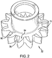
- drive gear 32 includes a gear body 71 that may be press-fit onto drive shaft 34 or machined from a common barstock. Of course, drive gear 32 could also be mounted to drive shaft 34 through a key or through a brazed connection.
- Gear body 71 includes a root circle 78 from which radially outwardly project a plurality of gear teeth, one of which is indicated at 84.
- each gear tooth 84 includes a base portion 90 positioned at root circle 78, a tip portion 92, a leading edge 94, and a trailing edge 96.
- Each gear tooth 84 also includes a first radially outwardly facing surface 99 and a second, opposing, radially outwardly facing surface 104.
- a circular thickness 108 is defined between leading edge 94 and trailing edge 96.
- the gears are a steel, but could be made from any number of other materials.
- gear tooth 84 includes a chamfered portion 116 that extends from leading edge 94 toward trailing edge 96 across a portion of circular thickness 108.
- chamfered portion 116 extends across about 43% of the circular thickness 108 so as to define a roll off width 120.
- chamfered portion 116 extends across about 40% of circular thickness 108.
- chamfered portion 116can range from about 15% to about 50% of the tooth circular thickness containing a chamfered portion.
- Chamfered portion 116 includes a height of between about 2 and about 4 light bands (between about 0.00058 mm and about 0.000116 mm). At this point, it should be understood that while shown on first radially outwardly facing surface 99 second radially outwardly facing surface 104 may also include a chamfered portion.
- Chamfered portion 116 may include a surface flatness of about 2.54 microns. The particular size and shape of the chamfered portion may vary and may be tailored to a particular tooth shape. Chamfered portion 116 forms an edge break that enhances and retains a surface film of lubricant (fuel) that increases service life of the pump, allows for increased pressures and speeds as well as the use of non-traditional bearing and gear material couples. It should be appreciated that the chamfered portion improves fluid entrainment results in an increase in fluid film. The increase in fluid film can results in a film region that exceeds a boundary layer or mixed film layer into full hydrodynamic lubrication which improves the load carrying capability of the gear and bearing material couple, improves heat transfer, and reduces friction and heat generation. Chamfered portion 116 may be formed through various laser etching processes that ensure high repeatability and maintenance of tolerances.
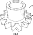
- Gear 130 may take the form of a drive gear or a driven gear.
- gear 130 includes a gear body 134 having a root circle 136.
- each gear tooth 138 includes a base portion 144 at root circle 136 and a tip portion 146.
- Each gear tooth 138 also includes a leading edge 148 and a trailing edge 150 between which is defined a circular thickness 154.
- gear tooth 138 includes a first chamfered portion 158 that extends from leading edge 148 toward trailing edge 150 across about 15% of circular thickness 154.
- Gear tooth 138 also includes a second chamfered portion 160 that extends from trailing edge 150 toward leading edge 148 across about 15% of circular thickness 154.
- Each chamfered portion 158 and 160 includes a height of between about 2 and about 4 light bands (between about 0.00058 mm and about 0.000116 mm) and a surface flatness of about 1 micron.
- first radially outwardly facing surface 99 second radially outwardly facing surface 104 may also include a chamfered portion.
- Each chamfered portion 158, 160 forms an edge break, which depending upon a direction of rotation, enhances and retains a surface film of lubricant (fuel) that increases service life of the pump, allows for increased pressures and speeds as well as the use of non-traditional bearing and gear material couples.
- Chamfered portions 158 and 160 improve fluid entrainment that results in an increase in fluid film generated. The increase in the fluid film can bring the film region out of a boundary layer or mixed film layer into full hydrodynamic lubrication which improves the load carrying capability of the gear and bearing material couple, improves heat transfer, and reduces friction and heat generation.
Landscapes
- Engineering & Computer Science (AREA)
- Mechanical Engineering (AREA)
- General Engineering & Computer Science (AREA)
- Rotary Pumps (AREA)
- Details And Applications Of Rotary Liquid Pumps (AREA)
Applications Claiming Priority (1)
| Application Number | Priority Date | Filing Date | Title |
|---|---|---|---|
| US17/132,534 US11624360B2 (en) | 2020-12-23 | 2020-12-23 | Gear pump with gear including etched surfaces |
Publications (1)
| Publication Number | Publication Date |
|---|---|
| EP4019775A1 true EP4019775A1 (fr) | 2022-06-29 |
Family
ID=78528772
Family Applications (1)
| Application Number | Title | Priority Date | Filing Date |
|---|---|---|---|
| EP21206565.0A Pending EP4019775A1 (fr) | 2020-12-23 | 2021-11-04 | Pompe à engrenages avec engrenages comprenant des surfaces gravées |
Country Status (2)
| Country | Link |
|---|---|
| US (1) | US11624360B2 (fr) |
| EP (1) | EP4019775A1 (fr) |
Families Citing this family (2)
| Publication number | Priority date | Publication date | Assignee | Title |
|---|---|---|---|---|
| US11662026B2 (en) | 2021-08-16 | 2023-05-30 | Hamilton Sandstrand Corporation | Seal with surface indents |
| US11713716B2 (en) * | 2021-08-16 | 2023-08-01 | Hamilton Sundstrand Corporation | Gear and bearing indents to induce fluid film |
Citations (8)
| Publication number | Priority date | Publication date | Assignee | Title |
|---|---|---|---|---|
| GB574364A (en) * | 1943-06-09 | 1946-01-02 | Frank Robert Bell | Improvements in or relating to rotary pumps and engines of the gear-wheel type |
| JPS51109401U (fr) * | 1975-03-01 | 1976-09-03 | ||
| RU2074986C1 (ru) * | 1994-07-26 | 1997-03-10 | Акционерное общество закрытого типа "Инженерный центр "Феникс" | Шестеренная гидравлическая машина |
| EP1832370B1 (fr) * | 2006-03-09 | 2008-10-01 | Winergy AG | Procédé de fabrication d'engrenages à développante de roues dentées |
| WO2009098773A1 (fr) * | 2008-02-08 | 2009-08-13 | Shimadzu Corporation | Pompe à engrenages ou moteur |
| DE102012205406A1 (de) * | 2012-04-03 | 2013-10-10 | Robert Bosch Gmbh | Hydrostatische Verdrängermaschine mit gekrümmter Eingriffslinie und Flankenlinienrücknahme |
| US20140322060A1 (en) * | 2011-12-06 | 2014-10-30 | Sumitomo Precision Products Co., Ltd. | Fluid-pressure apparatus |
| WO2017143340A1 (fr) * | 2016-02-18 | 2017-08-24 | Purdue Research Foundation | Machine à engrenages extérieurs à compensation de pression |
Family Cites Families (12)
| Publication number | Priority date | Publication date | Assignee | Title |
|---|---|---|---|---|
| US4728201A (en) | 1986-12-17 | 1988-03-01 | Kurt Manufacturing Company, Inc. | Low velocity energized gas particle bearing |
| US5164957A (en) | 1991-08-20 | 1992-11-17 | Westinghouse Electric Corp. | Energy beam director apparatus |
| EP1322445A1 (fr) | 2000-09-25 | 2003-07-02 | GearCon GmbH | Procede pour faconner des dentures et des profiles |
| AT5886U1 (de) * | 2002-03-27 | 2003-01-27 | Plansee Ag | Gesinterte schalt- oder schiebemuffe |
| DE10249818B4 (de) | 2002-10-24 | 2005-10-20 | Daimler Chrysler Ag | Oberfläche eines Körpers, auf dem ein anderer Körper in einer bevorzugten Gleitrichtung gegeneinander gleitend anordenbar ist |
| US6939093B2 (en) * | 2002-12-05 | 2005-09-06 | Joseph L. Arvin | Chamfer hob and method of use thereof |
| DE102005027048A1 (de) * | 2005-06-10 | 2006-12-14 | Gkn Sinter Metals Gmbh | Gesintertes Verzahnungselement mit lokal-selektiver Oberflächenverdichtung |
| DE202006014930U1 (de) | 2006-09-28 | 2008-02-14 | Trw Automotive Gmbh | Hydraulische Vorrichtung |
| EP2188529A4 (fr) * | 2007-09-07 | 2014-03-05 | Gkn Sinter Metals Inc | Composant de poudre métallique précis, assemblage et procédé |
| WO2015143141A1 (fr) | 2014-03-21 | 2015-09-24 | Imo Industries, Inc. | Pompe à engrenages avec flasques latéraux ou paliers ayant des rainures en spirale |
| US9488173B2 (en) * | 2014-07-31 | 2016-11-08 | Hamilton Sundstrand Corporation | Gear pump drive gear stationary bearing |
| DE102015201727A1 (de) * | 2015-02-02 | 2016-08-04 | Robert Bosch Gmbh | Innenzahnradpumpe für eine hydraulische Fahrzeugbremsanlage und Verfahren zum Herstellen der Innenzahnradpumpe |
-
2020
- 2020-12-23 US US17/132,534 patent/US11624360B2/en active Active
-
2021
- 2021-11-04 EP EP21206565.0A patent/EP4019775A1/fr active Pending
Patent Citations (8)
| Publication number | Priority date | Publication date | Assignee | Title |
|---|---|---|---|---|
| GB574364A (en) * | 1943-06-09 | 1946-01-02 | Frank Robert Bell | Improvements in or relating to rotary pumps and engines of the gear-wheel type |
| JPS51109401U (fr) * | 1975-03-01 | 1976-09-03 | ||
| RU2074986C1 (ru) * | 1994-07-26 | 1997-03-10 | Акционерное общество закрытого типа "Инженерный центр "Феникс" | Шестеренная гидравлическая машина |
| EP1832370B1 (fr) * | 2006-03-09 | 2008-10-01 | Winergy AG | Procédé de fabrication d'engrenages à développante de roues dentées |
| WO2009098773A1 (fr) * | 2008-02-08 | 2009-08-13 | Shimadzu Corporation | Pompe à engrenages ou moteur |
| US20140322060A1 (en) * | 2011-12-06 | 2014-10-30 | Sumitomo Precision Products Co., Ltd. | Fluid-pressure apparatus |
| DE102012205406A1 (de) * | 2012-04-03 | 2013-10-10 | Robert Bosch Gmbh | Hydrostatische Verdrängermaschine mit gekrümmter Eingriffslinie und Flankenlinienrücknahme |
| WO2017143340A1 (fr) * | 2016-02-18 | 2017-08-24 | Purdue Research Foundation | Machine à engrenages extérieurs à compensation de pression |
Also Published As
| Publication number | Publication date |
|---|---|
| US20220196013A1 (en) | 2022-06-23 |
| US11624360B2 (en) | 2023-04-11 |
Similar Documents
| Publication | Publication Date | Title |
|---|---|---|
| Lynwander | Gear drive systems: Design and application | |
| EP4019775A1 (fr) | Pompe à engrenages avec engrenages comprenant des surfaces gravées | |
| EP3299686A1 (fr) | Élément de coulissement | |
| EP3120027B1 (fr) | Pompe à engrenages avec flasques latéraux ou paliers ayant des rainures en spirale | |
| CN101265917B (zh) | 齿轮驱动涡轮压缩机 | |
| US9127674B2 (en) | High efficiency fixed displacement vane pump including a compression spring | |
| US6991574B2 (en) | Dual level oil impeller for drive axle assembly | |
| CN111828822A (zh) | 车辆用电动机的轴承的润滑机构 | |
| US20190338771A1 (en) | Variable displacement pump | |
| EP1165979B1 (fr) | Palier hybride | |
| CN112460241B (zh) | 一种抑制传动系统搅油功率损耗设计方法 | |
| US8789657B2 (en) | Centrifugal lubricating apparatus | |
| JP4423803B2 (ja) | 横軸型ポンプ | |
| EP2065561A2 (fr) | Pompe à ailettes dotée de paliers radiaux à coussinets basculants | |
| EP0310292A2 (fr) | Douille de palier pour une pompe à engrenages | |
| CN114162337A (zh) | 一种降低高速弧齿锥齿轮喷油润滑风阻损失的挡风罩系统 | |
| CN102132074B (zh) | 斜面摩擦环齿轮 | |
| WO2015098896A1 (fr) | Dispositif de palier et pompe | |
| CN113286947A (zh) | 具有轴承润滑系统的泵 | |
| CN113323868B (zh) | 一种液体输送系统及风力发电机齿轮箱润滑油输送系统 | |
| CN210919828U (zh) | 一种用于流体泵的轴承 | |
| US20110073412A1 (en) | Axial fan compact bearing viscous pump | |
| EP3114350B1 (fr) | Système de pompe à trois roues dentées pour fluides à faible viscosité | |
| CN223984787U (zh) | 一种双向增速油泵 | |
| EP2103778A1 (fr) | Compresseur ou extenseur volumétrique à palettes |
Legal Events
| Date | Code | Title | Description |
|---|---|---|---|
| PUAI | Public reference made under article 153(3) epc to a published international application that has entered the european phase |
Free format text: ORIGINAL CODE: 0009012 |
|
| STAA | Information on the status of an ep patent application or granted ep patent |
Free format text: STATUS: THE APPLICATION HAS BEEN PUBLISHED |
|
| AK | Designated contracting states |
Kind code of ref document: A1 Designated state(s): AL AT BE BG CH CY CZ DE DK EE ES FI FR GB GR HR HU IE IS IT LI LT LU LV MC MK MT NL NO PL PT RO RS SE SI SK SM TR |
|
| STAA | Information on the status of an ep patent application or granted ep patent |
Free format text: STATUS: REQUEST FOR EXAMINATION WAS MADE |
|
| 17P | Request for examination filed |
Effective date: 20221214 |
|
| RBV | Designated contracting states (corrected) |
Designated state(s): AL AT BE BG CH CY CZ DE DK EE ES FI FR GB GR HR HU IE IS IT LI LT LU LV MC MK MT NL NO PL PT RO RS SE SI SK SM TR |
|
| STAA | Information on the status of an ep patent application or granted ep patent |
Free format text: STATUS: EXAMINATION IS IN PROGRESS |
|
| 17Q | First examination report despatched |
Effective date: 20240912 |