EP4019785B1 - Kabinenluftverdichter mit flüssigkeitsgekühltem mantel - Google Patents
Kabinenluftverdichter mit flüssigkeitsgekühltem mantel Download PDFInfo
- Publication number
- EP4019785B1 EP4019785B1 EP21217089.8A EP21217089A EP4019785B1 EP 4019785 B1 EP4019785 B1 EP 4019785B1 EP 21217089 A EP21217089 A EP 21217089A EP 4019785 B1 EP4019785 B1 EP 4019785B1
- Authority
- EP
- European Patent Office
- Prior art keywords
- compressor
- aft
- motor
- bearing
- cooling jacket
- Prior art date
- Legal status (The legal status is an assumption and is not a legal conclusion. Google has not performed a legal analysis and makes no representation as to the accuracy of the status listed.)
- Active
Links
Images

Classifications
-
- F—MECHANICAL ENGINEERING; LIGHTING; HEATING; WEAPONS; BLASTING
- F04—POSITIVE - DISPLACEMENT MACHINES FOR LIQUIDS; PUMPS FOR LIQUIDS OR ELASTIC FLUIDS
- F04D—NON-POSITIVE-DISPLACEMENT PUMPS
- F04D29/00—Details, component parts, or accessories
- F04D29/58—Cooling; Heating; Diminishing heat transfer
- F04D29/5806—Cooling the drive system
-
- B—PERFORMING OPERATIONS; TRANSPORTING
- B64—AIRCRAFT; AVIATION; COSMONAUTICS
- B64D—EQUIPMENT FOR FITTING IN OR TO AIRCRAFT; FLIGHT SUITS; PARACHUTES; ARRANGEMENT OR MOUNTING OF POWER PLANTS OR PROPULSION TRANSMISSIONS IN AIRCRAFT
- B64D13/00—Arrangements or adaptations of air-treatment apparatus for aircraft crew or passengers, or freight space
- B64D13/06—Arrangements or adaptations of air-treatment apparatus for aircraft crew or passengers, or freight space the air being conditioned
- B64D13/08—Arrangements or adaptations of air-treatment apparatus for aircraft crew or passengers, or freight space the air being conditioned the air being heated or cooled
-
- F—MECHANICAL ENGINEERING; LIGHTING; HEATING; WEAPONS; BLASTING
- F04—POSITIVE - DISPLACEMENT MACHINES FOR LIQUIDS; PUMPS FOR LIQUIDS OR ELASTIC FLUIDS
- F04D—NON-POSITIVE-DISPLACEMENT PUMPS
- F04D25/00—Pumping installations or systems
- F04D25/02—Units comprising pumps and their driving means
- F04D25/06—Units comprising pumps and their driving means the pump being electrically driven
-
- H—ELECTRICITY
- H02—GENERATION; CONVERSION OR DISTRIBUTION OF ELECTRIC POWER
- H02K—DYNAMO-ELECTRIC MACHINES
- H02K5/00—Casings; Enclosures; Supports
- H02K5/04—Casings or enclosures characterised by the shape, form or construction thereof
- H02K5/20—Casings or enclosures characterised by the shape, form or construction thereof with channels or ducts for flow of cooling medium
- H02K5/203—Casings or enclosures characterised by the shape, form or construction thereof with channels or ducts for flow of cooling medium specially adapted for liquids, e.g. cooling jackets
-
- B—PERFORMING OPERATIONS; TRANSPORTING
- B64—AIRCRAFT; AVIATION; COSMONAUTICS
- B64D—EQUIPMENT FOR FITTING IN OR TO AIRCRAFT; FLIGHT SUITS; PARACHUTES; ARRANGEMENT OR MOUNTING OF POWER PLANTS OR PROPULSION TRANSMISSIONS IN AIRCRAFT
- B64D13/00—Arrangements or adaptations of air-treatment apparatus for aircraft crew or passengers, or freight space
- B64D13/06—Arrangements or adaptations of air-treatment apparatus for aircraft crew or passengers, or freight space the air being conditioned
- B64D2013/0603—Environmental Control Systems
- B64D2013/0644—Environmental Control Systems including electric motors or generators
Definitions
- the subject matter disclosed herein relates to aircraft environmental control and more specifically to a cabin air compressor with a liquid cooled jacket.
- Environmental control systems are utilized on various types of aircraft for several purposes, such as in cooling systems for the aircraft.
- components of the ECS may be utilized to remove heat from various aircraft lubrication and electrical systems and/or used to condition aircraft cabin air.
- the cabin air conditioner includes one or more cabin air compressors (CACs) which compress air entering the system, from an outside source or from a ram air system. The compressed air is delivered to an environmental control system to bring it to a desired temperature, and then the compressed air is delivered to the aircraft cabin. After passing through the cabin, the air is typically exhausted to the outside.
- the CACs are typically driven by air-cooled electric motors, which are cooled by a flow of cooling air typically drawn by the ram air system. Conditions of the CAC, such as heating of the components therein during use, are controlled to extend a useful life of the CACs.
- US 2008/168796 A1 discloses a cabin air compressor with a cooling jacket.
- a compressor as defined by claim 1 for use as a cabin air compressor (CAC) of an aircraft environmental control system.
- CAC cabin air compressor
- an inlet port and an outlet port of the cooling jacket are fluidly coupled via at least one internal passage or bladder within the cooling jacket.
- cooling jacket may at least partially include insulating material.
- the cooling jacket may be configured to cool a motor, a forward motor support bearing, and an aft motor support bearing of the compressor.
- the cooling jacket may at least partially include a first passage through which a motor air cooling inlet channel of the CAC extends; the cooling jacket may at least partially include a defines a second passage through which a bearing air cooling inlet channel of the CAC extends; and the cooling jacket may at least partially include a third passage through which a cooling outlet channel of the CAC extends.
- Aforward end of the supplemental cooling jacket may be configured to be removably attached to a flange of the CAC.
- an inlet portion of the CAC extends aft of the forward end to a diffuser portion of the CAC; the diffuser portion extends aft of the inlet portion to a compressor rotor portion of the CAC; the compressor rotor portion extends aft of the diffuser portion to a forward bearing portion of the CAC; the forward bearing portion extends aft of the compressor rotor portion to a motor portion of the CAC; the motor portion extends aft of the forward bearing portion to an aft bearing portion of the CAC; and the aft bearing portion extends aft of the motor portion to the aft end of the CAC; wherein the cooling jacket extends over the aft bearing portion, the motor portion and the forward bearing portion of the CAC.
- the cooling jacket terminates at the forward bearing portion of the CAC, adjacent the compressor rotor portion.
- a forward journal bearing of the forward bearing portion is rotationally supported between a forward stationary member of the CAC case and a forward motor shaft operationally connected to the motor; an aft journal bearing of the aft bearing portion is rotationally supported between an aft stationary member of the CAC case and an aft motor shaft operationally connected to the motor.
- a thrust bearing of the aft bearing portion is rotationally supported between the aft end of the CAC case and the aft motor shaft.
- An aircraft including an environmental control system, which includes a compressor having any of the above aspects.
- FIG. 1 illustrates an example of a commercial aircraft 10 having aircraft engines surrounded by (or otherwise carried in) a nacelle 20 housing therein a gas turbine engine.
- the aircraft 10 includes two wings 22 that can each include one or more slats 24 and one or more flaps 26.
- the aircraft may further include ailerons 27, spoilers 28, horizontal stabilizer trim tabs 29, horizontal stabilizer 30 and rudder 31, and vertical stabilizer 32 (the tail structure being collectively referred to as an and empennage) each of which may be typically referred to as "control surfaces" as they are movable under aircraft power systems.
- the aircraft 10 may include an environmental control system (ECS) 50, illustrated schematically, which conditions air that is delivered to the passenger cabin 60 of the aircraft 10.
- the ECS 50 may receive compressed air from a cabin air compressor (CAC) 100, as indicated above.
- CAC cabin air compressor
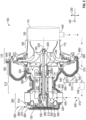
- the components of a CAC 100 are shown in FIG. 2 and includes a CAC case 115 extending from a case forward end 110 to a case aft end 130, where the case aft end 130 is spaced apart from the case forward end 110 in an axial aft direction 140.
- An inlet portion 150 (otherwise referred to as a compressor inlet portion), shown schematically, is defined by the CAC 100, aft of the case forward end 110.
- the inlet portion 150 extends in the axial aft direction 140 from the case forward end 110 to an add heat portion 160 of the CAC 100.
- the inlet portion 150 of the CAC 100 receives, for example, air from outside the aircraft, e.g., from a ram air system of the aircraft 10.
- the add heat portion 160 is defined by the CAC 100, aft of the inlet portion 150.
- the add heat portion 160 extends in the axial aft direction 140 from the inlet portion 150 to a compressor rotor portion 170 of the CAC 100
- the compressor rotor portion 170 is defined by the CAC 100, aft of the add heat portion 160.
- the compressor rotor portion 170 extends axially aft from the add heat portion 160 to a forward bearing portion 180.
- a compressor rotor 190 is housed within the compressor rotor portion 170.
- the compressor rotor 190 rotates about a compressor drive rod 200 (or center drive rod) that extends in the axial aft direction 140 from the compressor rotor 190, toward the case aft end 130, and rotates about a rotation axis 205 (or center rotation axis).
- the forward bearing portion 180 is defined by the CAC 100, aft of the compressor rotor portion 170.
- the forward bearing portion 180 extends in the axial aft direction 140 from the compressor rotor portion 170 to a motor portion 210.
- the compressor drive rod 200 extends axially through the forward bearing portion 180 of the CAC 100.
- a forward motor shaft 215 within the forward bearing portion 180 supports the compressor drive rod 200 via a forward drive rod support 220 that extends in the radial outer direction 230 between the forward motor shaft 215 and compressor drive rod 200.
- a forward journal bearing 240 (or forward motor support bearing) within the forward bearing portion 180 is rotationally positioned between a forward case structure 250 (or stationary member) and the forward motor shaft 215.
- the motor portion 210 of the CAC 100 is defined by the CAC 100, aft of the forward bearing portion 180.
- the motor portion 210 extends in the axial aft direction 140, from the forward bearing portion 180 to an aft bearing portion 260.
- the motor stator 270 is radially exterior to and axially aligned with the motor rotor 280.
- the compressor drive rod 200 extends axially through the motor portion 210 of the CAC 100 and is operationally connected to the motor rotor 280, e.g., to drive the compressor rotor 190.
- the aft bearing portion 260 of the CAC 100 is defined by the CAC 100, aft of the motor portion 210.
- the aft bearing portion 260 extends in the axial aft direction 140, from the motor portion 210 to the case aft end 130 of the CAC case 110.
- the compressor drive rod 200 extends the axial aft direction 140, into the aft bearing portion 260 of the CAC 100.
- An aft motor shaft 290 (or thrust shaft) extends in the axial aft direction 140 from the motor rotor 280 to a thrust plate 300 at the case aft end 130 of the CAC case 110.
- the aft motor shaft 290 supports the compressor drive rod 200 via an aft drive rod support 310 that extends in the radial outer direction 230 between the aft motor shaft 290 and compressor drive rod 200.
- An aft journal bearing 320 is within the aft bearing portion 260, rotationally supported between the aft motor shaft 290 and an aft support structure 330 (another stationary member) of the CAC case 110, thereby supporting the compressor drive rod 200.
- a thrust bearing 340 engages the thrust plate 300 at the aft end of the CAC case 110.
- the aft journal bearing 320 and thrust bearing 340 may together be considered aft motor support bearings.
- a bearing cooling circuit 350 is defined in the CAC 100 for directing a bearing cooling flow 360 of air through the CAC 100.
- the cooling air may also be from a primary heat exchanger of the aircraft or may be from a different source.
- the bearing cooling circuit 350 includes a bearing cooling inlet channel 370, formed as an inlet passage in the aft bearing portion 260 of the CAC case 110.
- a cooling outlet channel 380 is formed as an outlet passage in the forward bearing portion 180 of the CAC case 110.
- the CAC 100 is configured so that bearing cooling flow 360 is directed around the thrust bearing 340, over the aft journal bearing 320, between the compressor drive rod 200 and the motor rotor 280, over the forward journal bearing 240, and out of the cooling outlet channel 380.
- the bearing cooling inlet channel 370 may extend along a bearing cooling inlet channel axis 390 that is normal to the rotation axis 205 for the compressor rotor 190. This configuration is not intended on limiting an orientation of the bearing cooling inlet channel 370.
- a motor cooling circuit 400 is defined in the CAC 100 for directing a motor cooling flow 410 of air through the CAC 100.
- the motor cooling circuit 400 includes a motor cooling inlet channel 420 formed in the aft bearing portion 260 of the CAC 100.
- the motor cooling inlet channel 420 receives the motor cooling flow 410 via a motor cooling duct 430 connected to a bleed channel 440 that is tapped off of the inlet portion 150 of the CAC 100.
- the CAC 100 is configured so that motor cooling flow 410 is directed between the motor rotor 280 and motor stator 270, between the motor stator 270 and the CAC case 110, and out of the cooling outlet channel 380.
- the motor cooling inlet channel 420 may extend along a motor cooling inlet channel axis 450 that is normal to the rotational axis for the compressor rotor 190, and e.g., parallel to bearing cooling inlet channel axis 390. This configuration is not intended on limiting an orientation of the bearing cooling inlet channel 370.
- CAC motor reliability is dependent on the motor and bearings operating efficiently, meaning at least in part that the components are prevented from overheating.
- the CAC motor, as indicated above is cooled at least partially by cooling airflows, which under certain conditions may be insufficient to provide the desired cooling levels to the motor components. This may have a direct impact on system performance.
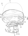
- the CAC 100 includes a supplemental cooling jacket 500 (the jacket).
- the jacket 500 is formed of a synthetic fabric, positioned around the CAC case 110 and conforms to the shape of the CAC case 110.
- the jacket 500 is configured to direct a supplemental cooling medium 510 through it.
- the supplemental cooling medium 510 is a liquid.
- the jacket 500 includes an inlet port 520 ( FIGS. 2 and 3 ) and an outlet port 530 ( FIGS. 2 and 3 ), fluidly coupled via at least one internal passage or bladder 535 within the jacket 500.
- the inlet and the outlet ports 520, 530 may respectively include quick release adaptors 540, 550, to respectively connect with inlet and outlet conduits 560, 570.
- the jacket 500 is at least partially filled with insulating material 580.
- the jacket 500 is disposed around portions of the CAC case 110 that house the motor 265 and forward and aft journal bearings 240, 320. That is, the jacket 500 extends over the aft bearing portion 260, the motor portion 210 and the forward bearing portion 180 of the CAC 100. The jacket 500 terminates at the forward bearing portion 180 of the CAC 100, adjacent the compressor rotor portion 170. With this configuration, the forward bearing portion 180, the motor portion 210 and the aft bearing portion 260, and moving components therein, are configured to be cooled by the jacket 500..
- a primary heat removal circuit of the disclosed embodiments includes heat being removed from the motor portion 210, including the motor 265 therein, and the forward and aft bearing portions 180, 260, the bearings therein, including the forward and aft journal bearings 240, 320, and the thrust bearing 340, via convection by the motor cooling flow 410, and then by the motor cooling flow 410 being cooled by convection against the case 115.
- the case 115 conducts heat to the jacket 500, and the jacket 500 removes heat by convection via fluid flowing in the jacket 500
- the CAC 100 is not covered by the jacket 500 ( FIGS. 2 and 3 ).
- the jacket 500 may be sized and configured to cover more or less of the CAC case 110, such as, for example, covering only the motor portion 210. In some embodiments, more than one jacket 500 is utilized, where each jacket covers one or more portions of the CAC case 110.
- the jacket 500 may define a first passage or aperture 600 through which the motor air cooling inlet channel 420 ( FIGS. 2 and 3 ) of the CAC 100 extends.
- the jacket 500 may further define a second passage or aperture 610 through which the bearing cooling inlet channel 370 of the CAC 100 extends.
- the jacket 500 may further define a third passage or aperture 630 through which the cooling outlet channel 380 of the CAC 100 extends.
- a forward end 640 of the jacket 500 may be removably attached to a flange 650 or other case mounting structure 660 of the CAC 100, to enable removal as needed.
Landscapes
- Engineering & Computer Science (AREA)
- Power Engineering (AREA)
- Mechanical Engineering (AREA)
- General Engineering & Computer Science (AREA)
- Health & Medical Sciences (AREA)
- General Health & Medical Sciences (AREA)
- Pulmonology (AREA)
- Aviation & Aerospace Engineering (AREA)
- Physics & Mathematics (AREA)
- Thermal Sciences (AREA)
- Structures Of Non-Positive Displacement Pumps (AREA)
Claims (11)
- Verdichter, der zur Verwendung als Kabinenluftverdichter (cabin air compressor - CAC) eines Klimatisierungssystems eines Luftfahrzeugs geeignet ist, wobei der Verdichter Folgendes umfasst:ein Verdichtergehäuse (115), das ein vorderes Ende (110) und ein hinteres Ende (130), das axial von dem vorderen Ende beabstandet ist, definiert, wobei das vordere Ende einen Verdichtereinlass (150) definiert; undeinen Kühlmantel (500),wobei der Kühlmantel so konfiguriert ist, dass ein Kühlmittel (510) durch ihn hindurchgeleitet wird;dadurch gekennzeichnet, dassder Kühlmantel ein zusätzlicher Kühlmantel ist, der um mindestens einen Abschnitt des Verdichtergehäuses herum positioniert ist und sich mindestens teilweise an das Verdichtergehäuse anpasst, und dass der zusätzliche Kühlmantel (500) aus einem synthetischen Gewebe gebildet ist.
- Verdichter nach Anspruch 1, wobei:
ein Einlassanschluss (520) und ein Auslassanschluss (530) des Kühlmantels über mindestens einen inneren Durchgang oder eine Blase (535) innerhalb des Kühlmantels fluidisch gekoppelt sind. - Verdichter nach einem der vorhergehenden Ansprüche, wobei:
der Kühlmantel (500) mindestens teilweise Isoliermaterial (580) beinhaltet. - Verdichter nach einem der vorhergehenden Ansprüche, wobei:der Kühlmantel so konfiguriert ist, dass er einen Motor (265),ein vorderes Motorstützlager (240) und ein hinteres Motorstützlager (320) des Verdichters kühlt.
- Verdichter nach einem der vorhergehenden Ansprüche, wobei:der Kühlmantel mindestens teilweise einen ersten Durchgang (600) beinhaltet, durch den sich ein Motorluftkühlungseinlasskanal (420) des Verdichters erstreckt;der Kühlmantel mindestens teilweise einen zweiten Durchgang definiert, durch den sich ein Lagerluftkühlungseinlasskanal des Verdichters erstreckt; undder Kühlmantel mindestens teilweise einen dritten Durchgang beinhaltet, durch den sich ein Kühlauslasskanal des Verdichters erstreckt.
- Verdichter nach einem der vorhergehenden Ansprüche, wobei:
ein vorderes Ende (640) des Kühlmantels so konfiguriert ist, dass es abnehmbar an einem Flansch (650) des Verdichters befestigt werden kann. - Verdichter nach einem der vorhergehenden Ansprüche, wobei:sich ein Einlassabschnitt des Verdichters von hinter dem vorderen Ende bis zu einem Diffusorabschnitt des Verdichters erstreckt;sich der Diffusorabschnitt von hinter dem Einlassabschnitt bis zu einem Verdichterrotorabschnitt des Verdichters erstreckt;sich der Verdichterrotorabschnitt von hinter dem Diffusorabschnitt bis zu einem vorderen Lagerabschnitt des Verdichters erstreckt;sich der vordere Lagerabschnitt von hinter dem Verdichterrotorabschnitt bis zu einem Motorabschnitt des Verdichters erstreckt;sich der Motorabschnitt von hinter dem vorderen Lagerabschnitt bis zu einem hinteren Lagerabschnitt des Verdichters erstreckt; undsich der hintere Lagerabschnitt von hinter dem Motorabschnitt bis zu dem hinteren Ende des Verdichters erstreckt;wobei sich der Kühlmantel über den hinteren Lagerabschnitt, den Motorabschnitt und den vorderen Lagerabschnitt des Verdichters erstreckt.
- Verdichter nach Anspruch 7, wobei:
der zusätzliche Kühlmantel an dem vorderen Lagerabschnitt des Verdichters benachbart zu dem Verdichterrotorabschnitt endet. - Verdichter nach Anspruch 7 oder 8, wobei:ein vorderes Gleitlager (240) des vorderen Lagerabschnitts drehbar zwischen einem vorderen stationären Element des Verdichtergehäuses und einer vorderen Motorwelle abgestützt ist, die betriebsmäßig mit dem Motor verbunden ist;ein hinteres Gleitlager (320) des hinteren Lagerabschnitts drehbar zwischen einem hinteren stationären Element des Verdichtergehäuses und einer hinteren Motorwelle abgestützt ist, die betriebsmäßig mit dem Motor verbunden ist.
- Verdichter nach Anspruch 9, wobei:
ein Drucklager des hinteren Lagerabschnitts drehbar zwischen dem hinteren Ende des Verdichtergehäuses und der hinteren Motorwelle abgestützt ist. - Luftfahrzeug, Folgendes umfassend:
ein Klimatisierungssystem, beinhaltend den Verdichter nach einem der vorhergehenden Ansprüche.
Applications Claiming Priority (1)
| Application Number | Priority Date | Filing Date | Title |
|---|---|---|---|
| US17/132,749 US11658542B2 (en) | 2020-12-23 | 2020-12-23 | Cabin air compressor with liquid cooled jacket |
Publications (2)
| Publication Number | Publication Date |
|---|---|
| EP4019785A1 EP4019785A1 (de) | 2022-06-29 |
| EP4019785B1 true EP4019785B1 (de) | 2024-10-30 |
Family
ID=80035119
Family Applications (1)
| Application Number | Title | Priority Date | Filing Date |
|---|---|---|---|
| EP21217089.8A Active EP4019785B1 (de) | 2020-12-23 | 2021-12-22 | Kabinenluftverdichter mit flüssigkeitsgekühltem mantel |
Country Status (2)
| Country | Link |
|---|---|
| US (1) | US11658542B2 (de) |
| EP (1) | EP4019785B1 (de) |
Families Citing this family (4)
| Publication number | Priority date | Publication date | Assignee | Title |
|---|---|---|---|---|
| JP7547292B2 (ja) * | 2021-08-10 | 2024-09-09 | 本田技研工業株式会社 | 複合動力システム |
| US20230331390A1 (en) * | 2022-04-19 | 2023-10-19 | Hamilton Sundstrand Corporation | Cabin air cooling system |
| US12395044B2 (en) | 2023-02-14 | 2025-08-19 | Hamilton Sundstrand Corporation | CAC motor auxiliary water cooling system |
| US12504016B2 (en) * | 2024-02-01 | 2025-12-23 | Hamilton Sundstrand Corporation | Bearing cooling flow path for a cabin air compressor |
Family Cites Families (11)
| Publication number | Priority date | Publication date | Assignee | Title |
|---|---|---|---|---|
| JP2004343857A (ja) | 2003-05-14 | 2004-12-02 | Kobe Steel Ltd | 液冷式モータ |
| CN101268282B (zh) * | 2005-09-19 | 2013-10-16 | 英格索尔-兰德公司 | 流体压缩系统 |
| DE102006003372A1 (de) | 2006-01-24 | 2007-08-09 | OCé PRINTING SYSTEMS GMBH | Anordnung und Verfahren zum Kühlen einer Maschinenkomponente |
| US7633193B2 (en) * | 2007-01-17 | 2009-12-15 | Honeywell International Inc. | Thermal and secondary flow management of electrically driven compressors |
| US7675209B2 (en) | 2007-02-01 | 2010-03-09 | Honeywell International Inc. | Electric motor cooling jacket |
| US8450888B2 (en) | 2009-04-20 | 2013-05-28 | General Electric Company | Integrated brushless starter/generator system |
| CN103532308B (zh) | 2013-10-30 | 2016-03-23 | 吴家伟 | 一种制冷剂液体冷却电机的半封螺杆压缩机 |
| CN203537174U (zh) | 2013-10-30 | 2014-04-09 | 吴家伟 | 一种制冷剂液体冷却电机的半封螺杆压缩机 |
| US10443619B2 (en) * | 2014-12-31 | 2019-10-15 | Hamilton Sundstrand Corporation | Motor housing assembly for a cabin air compressor |
| JP6982380B2 (ja) | 2016-03-08 | 2021-12-17 | コベルコ・コンプレッサ株式会社 | スクリュ圧縮機 |
| JP2017172444A (ja) * | 2016-03-23 | 2017-09-28 | 株式会社豊田自動織機 | 電動圧縮機、及び、冷却システム |
-
2020
- 2020-12-23 US US17/132,749 patent/US11658542B2/en active Active
-
2021
- 2021-12-22 EP EP21217089.8A patent/EP4019785B1/de active Active
Also Published As
| Publication number | Publication date |
|---|---|
| EP4019785A1 (de) | 2022-06-29 |
| US11658542B2 (en) | 2023-05-23 |
| US20220194601A1 (en) | 2022-06-23 |
Similar Documents
| Publication | Publication Date | Title |
|---|---|---|
| EP4019785B1 (de) | Kabinenluftverdichter mit flüssigkeitsgekühltem mantel | |
| EP4019784B1 (de) | Kabinenluftverdichter mit flüssigkeitsgekühltem durchgang im gehäuse | |
| CN110857663B (zh) | 嵌入式电机 | |
| EP2409919B1 (de) | Stauluftgebläsemotorkühlung | |
| EP2407380B1 (de) | Motorkühlung eines Kabinenluftkompressors | |
| EP1642828B1 (de) | Stauluftgebläsesystem einer Flugzeugklimaanlage | |
| EP1791756B1 (de) | Luftkreislaufmaschine für ein flugzeugklimaanlagensteuerungssystem | |
| EP3539876B1 (de) | Lagergehäuse für stauluftgebläse | |
| CN114790942A (zh) | 嵌入式电机 | |
| EP3543516B1 (de) | Kühlsystem und verfahren für einen elektrischen antriebsmotor | |
| CN114915101B (zh) | 用于集成到推进发动机中的电机 | |
| CN114915102B (zh) | 用于集成到推进发动机中的电机 | |
| EP4001663B1 (de) | Verbesserte lagerkühlungsschemen für flugzeuglüfter | |
| US20130101402A1 (en) | Fan housing with cooling slots | |
| US20130101436A1 (en) | Fan rotor with cooling holes | |
| EP3269946B1 (de) | Rotationsmaschinenkühlkörper | |
| EP4183996B1 (de) | Kühlsystem für einen heckkonusmontierten generator | |
| EP3539875B1 (de) | Gebläserad für stauluftgebläse | |
| EP3539877B1 (de) | Gehäuse für antrieb eines stauluftgebläses | |
| EP4265917A1 (de) | Kabinenluftkühlsystem | |
| EP4517073A2 (de) | Bypass-flusssteuerung für einen flugzeugwärmetauscher mit elektromotor |
Legal Events
| Date | Code | Title | Description |
|---|---|---|---|
| PUAI | Public reference made under article 153(3) epc to a published international application that has entered the european phase |
Free format text: ORIGINAL CODE: 0009012 |
|
| STAA | Information on the status of an ep patent application or granted ep patent |
Free format text: STATUS: THE APPLICATION HAS BEEN PUBLISHED |
|
| AK | Designated contracting states |
Kind code of ref document: A1 Designated state(s): AL AT BE BG CH CY CZ DE DK EE ES FI FR GB GR HR HU IE IS IT LI LT LU LV MC MK MT NL NO PL PT RO RS SE SI SK SM TR |
|
| STAA | Information on the status of an ep patent application or granted ep patent |
Free format text: STATUS: REQUEST FOR EXAMINATION WAS MADE |
|
| 17P | Request for examination filed |
Effective date: 20221228 |
|
| RBV | Designated contracting states (corrected) |
Designated state(s): AL AT BE BG CH CY CZ DE DK EE ES FI FR GB GR HR HU IE IS IT LI LT LU LV MC MK MT NL NO PL PT RO RS SE SI SK SM TR |
|
| GRAP | Despatch of communication of intention to grant a patent |
Free format text: ORIGINAL CODE: EPIDOSNIGR1 |
|
| STAA | Information on the status of an ep patent application or granted ep patent |
Free format text: STATUS: GRANT OF PATENT IS INTENDED |
|
| INTG | Intention to grant announced |
Effective date: 20240528 |
|
| GRAS | Grant fee paid |
Free format text: ORIGINAL CODE: EPIDOSNIGR3 |
|
| GRAA | (expected) grant |
Free format text: ORIGINAL CODE: 0009210 |
|
| STAA | Information on the status of an ep patent application or granted ep patent |
Free format text: STATUS: THE PATENT HAS BEEN GRANTED |
|
| AK | Designated contracting states |
Kind code of ref document: B1 Designated state(s): AL AT BE BG CH CY CZ DE DK EE ES FI FR GB GR HR HU IE IS IT LI LT LU LV MC MK MT NL NO PL PT RO RS SE SI SK SM TR |
|
| REG | Reference to a national code |
Ref country code: GB Ref legal event code: FG4D |
|
| REG | Reference to a national code |
Ref country code: CH Ref legal event code: EP |
|
| REG | Reference to a national code |
Ref country code: DE Ref legal event code: R096 Ref document number: 602021020960 Country of ref document: DE |
|
| REG | Reference to a national code |
Ref country code: IE Ref legal event code: FG4D |
|
| REG | Reference to a national code |
Ref country code: LT Ref legal event code: MG9D |
|
| REG | Reference to a national code |
Ref country code: NL Ref legal event code: MP Effective date: 20241030 |
|
| PG25 | Lapsed in a contracting state [announced via postgrant information from national office to epo] |
Ref country code: PT Free format text: LAPSE BECAUSE OF FAILURE TO SUBMIT A TRANSLATION OF THE DESCRIPTION OR TO PAY THE FEE WITHIN THE PRESCRIBED TIME-LIMIT Effective date: 20250228 Ref country code: HR Free format text: LAPSE BECAUSE OF FAILURE TO SUBMIT A TRANSLATION OF THE DESCRIPTION OR TO PAY THE FEE WITHIN THE PRESCRIBED TIME-LIMIT Effective date: 20241030 Ref country code: IS Free format text: LAPSE BECAUSE OF FAILURE TO SUBMIT A TRANSLATION OF THE DESCRIPTION OR TO PAY THE FEE WITHIN THE PRESCRIBED TIME-LIMIT Effective date: 20250228 |
|
| PG25 | Lapsed in a contracting state [announced via postgrant information from national office to epo] |
Ref country code: FI Free format text: LAPSE BECAUSE OF FAILURE TO SUBMIT A TRANSLATION OF THE DESCRIPTION OR TO PAY THE FEE WITHIN THE PRESCRIBED TIME-LIMIT Effective date: 20241030 Ref country code: NL Free format text: LAPSE BECAUSE OF FAILURE TO SUBMIT A TRANSLATION OF THE DESCRIPTION OR TO PAY THE FEE WITHIN THE PRESCRIBED TIME-LIMIT Effective date: 20241030 |
|
| REG | Reference to a national code |
Ref country code: AT Ref legal event code: MK05 Ref document number: 1737114 Country of ref document: AT Kind code of ref document: T Effective date: 20241030 |
|
| PG25 | Lapsed in a contracting state [announced via postgrant information from national office to epo] |
Ref country code: BG Free format text: LAPSE BECAUSE OF FAILURE TO SUBMIT A TRANSLATION OF THE DESCRIPTION OR TO PAY THE FEE WITHIN THE PRESCRIBED TIME-LIMIT Effective date: 20241030 |
|
| PG25 | Lapsed in a contracting state [announced via postgrant information from national office to epo] |
Ref country code: ES Free format text: LAPSE BECAUSE OF FAILURE TO SUBMIT A TRANSLATION OF THE DESCRIPTION OR TO PAY THE FEE WITHIN THE PRESCRIBED TIME-LIMIT Effective date: 20241030 |
|
| PG25 | Lapsed in a contracting state [announced via postgrant information from national office to epo] |
Ref country code: NO Free format text: LAPSE BECAUSE OF FAILURE TO SUBMIT A TRANSLATION OF THE DESCRIPTION OR TO PAY THE FEE WITHIN THE PRESCRIBED TIME-LIMIT Effective date: 20250130 |
|
| PG25 | Lapsed in a contracting state [announced via postgrant information from national office to epo] |
Ref country code: LV Free format text: LAPSE BECAUSE OF FAILURE TO SUBMIT A TRANSLATION OF THE DESCRIPTION OR TO PAY THE FEE WITHIN THE PRESCRIBED TIME-LIMIT Effective date: 20241030 Ref country code: AT Free format text: LAPSE BECAUSE OF FAILURE TO SUBMIT A TRANSLATION OF THE DESCRIPTION OR TO PAY THE FEE WITHIN THE PRESCRIBED TIME-LIMIT Effective date: 20241030 Ref country code: GR Free format text: LAPSE BECAUSE OF FAILURE TO SUBMIT A TRANSLATION OF THE DESCRIPTION OR TO PAY THE FEE WITHIN THE PRESCRIBED TIME-LIMIT Effective date: 20250131 |
|
| PG25 | Lapsed in a contracting state [announced via postgrant information from national office to epo] |
Ref country code: PL Free format text: LAPSE BECAUSE OF FAILURE TO SUBMIT A TRANSLATION OF THE DESCRIPTION OR TO PAY THE FEE WITHIN THE PRESCRIBED TIME-LIMIT Effective date: 20241030 |
|
| PG25 | Lapsed in a contracting state [announced via postgrant information from national office to epo] |
Ref country code: RS Free format text: LAPSE BECAUSE OF FAILURE TO SUBMIT A TRANSLATION OF THE DESCRIPTION OR TO PAY THE FEE WITHIN THE PRESCRIBED TIME-LIMIT Effective date: 20250130 |
|
| PG25 | Lapsed in a contracting state [announced via postgrant information from national office to epo] |
Ref country code: SM Free format text: LAPSE BECAUSE OF FAILURE TO SUBMIT A TRANSLATION OF THE DESCRIPTION OR TO PAY THE FEE WITHIN THE PRESCRIBED TIME-LIMIT Effective date: 20241030 |
|
| PG25 | Lapsed in a contracting state [announced via postgrant information from national office to epo] |
Ref country code: MC Free format text: LAPSE BECAUSE OF FAILURE TO SUBMIT A TRANSLATION OF THE DESCRIPTION OR TO PAY THE FEE WITHIN THE PRESCRIBED TIME-LIMIT Effective date: 20241030 |
|
| PG25 | Lapsed in a contracting state [announced via postgrant information from national office to epo] |
Ref country code: DK Free format text: LAPSE BECAUSE OF FAILURE TO SUBMIT A TRANSLATION OF THE DESCRIPTION OR TO PAY THE FEE WITHIN THE PRESCRIBED TIME-LIMIT Effective date: 20241030 |
|
| PG25 | Lapsed in a contracting state [announced via postgrant information from national office to epo] |
Ref country code: EE Free format text: LAPSE BECAUSE OF FAILURE TO SUBMIT A TRANSLATION OF THE DESCRIPTION OR TO PAY THE FEE WITHIN THE PRESCRIBED TIME-LIMIT Effective date: 20241030 |
|
| PG25 | Lapsed in a contracting state [announced via postgrant information from national office to epo] |
Ref country code: RO Free format text: LAPSE BECAUSE OF FAILURE TO SUBMIT A TRANSLATION OF THE DESCRIPTION OR TO PAY THE FEE WITHIN THE PRESCRIBED TIME-LIMIT Effective date: 20241030 |
|
| PG25 | Lapsed in a contracting state [announced via postgrant information from national office to epo] |
Ref country code: SK Free format text: LAPSE BECAUSE OF FAILURE TO SUBMIT A TRANSLATION OF THE DESCRIPTION OR TO PAY THE FEE WITHIN THE PRESCRIBED TIME-LIMIT Effective date: 20241030 |
|
| PG25 | Lapsed in a contracting state [announced via postgrant information from national office to epo] |
Ref country code: CZ Free format text: LAPSE BECAUSE OF FAILURE TO SUBMIT A TRANSLATION OF THE DESCRIPTION OR TO PAY THE FEE WITHIN THE PRESCRIBED TIME-LIMIT Effective date: 20241030 |
|
| PG25 | Lapsed in a contracting state [announced via postgrant information from national office to epo] |
Ref country code: IT Free format text: LAPSE BECAUSE OF FAILURE TO SUBMIT A TRANSLATION OF THE DESCRIPTION OR TO PAY THE FEE WITHIN THE PRESCRIBED TIME-LIMIT Effective date: 20241030 |
|
| REG | Reference to a national code |
Ref country code: CH Ref legal event code: PL Ref country code: DE Ref legal event code: R097 Ref document number: 602021020960 Country of ref document: DE |
|
| PG25 | Lapsed in a contracting state [announced via postgrant information from national office to epo] |
Ref country code: LU Free format text: LAPSE BECAUSE OF NON-PAYMENT OF DUE FEES Effective date: 20241222 |
|
| PLBE | No opposition filed within time limit |
Free format text: ORIGINAL CODE: 0009261 |
|
| STAA | Information on the status of an ep patent application or granted ep patent |
Free format text: STATUS: NO OPPOSITION FILED WITHIN TIME LIMIT |
|
| PG25 | Lapsed in a contracting state [announced via postgrant information from national office to epo] |
Ref country code: SE Free format text: LAPSE BECAUSE OF FAILURE TO SUBMIT A TRANSLATION OF THE DESCRIPTION OR TO PAY THE FEE WITHIN THE PRESCRIBED TIME-LIMIT Effective date: 20241030 |
|
| 26N | No opposition filed |
Effective date: 20250731 |
|
| REG | Reference to a national code |
Ref country code: BE Ref legal event code: MM Effective date: 20241231 |
|
| PG25 | Lapsed in a contracting state [announced via postgrant information from national office to epo] |
Ref country code: BE Free format text: LAPSE BECAUSE OF NON-PAYMENT OF DUE FEES Effective date: 20241231 |
|
| PG25 | Lapsed in a contracting state [announced via postgrant information from national office to epo] |
Ref country code: CH Free format text: LAPSE BECAUSE OF NON-PAYMENT OF DUE FEES Effective date: 20241231 |
|
| PG25 | Lapsed in a contracting state [announced via postgrant information from national office to epo] |
Ref country code: IE Free format text: LAPSE BECAUSE OF NON-PAYMENT OF DUE FEES Effective date: 20241222 |
|
| PGFP | Annual fee paid to national office [announced via postgrant information from national office to epo] |
Ref country code: DE Payment date: 20251126 Year of fee payment: 5 |
|
| PGFP | Annual fee paid to national office [announced via postgrant information from national office to epo] |
Ref country code: GB Payment date: 20251119 Year of fee payment: 5 |
|
| PGFP | Annual fee paid to national office [announced via postgrant information from national office to epo] |
Ref country code: FR Payment date: 20251120 Year of fee payment: 5 |