EP4019787B1 - Arrangement de servovanne - Google Patents
Arrangement de servovanne Download PDFInfo
- Publication number
- EP4019787B1 EP4019787B1 EP20461601.5A EP20461601A EP4019787B1 EP 4019787 B1 EP4019787 B1 EP 4019787B1 EP 20461601 A EP20461601 A EP 20461601A EP 4019787 B1 EP4019787 B1 EP 4019787B1
- Authority
- EP
- European Patent Office
- Prior art keywords
- flapper
- nozzles
- sheet
- orifices
- integral
- Prior art date
- Legal status (The legal status is an assumption and is not a legal conclusion. Google has not performed a legal analysis and makes no representation as to the accuracy of the status listed.)
- Active
Links
Images



Classifications
-
- F—MECHANICAL ENGINEERING; LIGHTING; HEATING; WEAPONS; BLASTING
- F15—FLUID-PRESSURE ACTUATORS; HYDRAULICS OR PNEUMATICS IN GENERAL
- F15B—SYSTEMS ACTING BY MEANS OF FLUIDS IN GENERAL; FLUID-PRESSURE ACTUATORS, e.g. SERVOMOTORS; DETAILS OF FLUID-PRESSURE SYSTEMS, NOT OTHERWISE PROVIDED FOR
- F15B13/00—Details of servomotor systems ; Valves for servomotor systems
- F15B13/02—Fluid distribution or supply devices characterised by their adaptation to the control of servomotors
- F15B13/04—Fluid distribution or supply devices characterised by their adaptation to the control of servomotors for use with a single servomotor
- F15B13/042—Fluid distribution or supply devices characterised by their adaptation to the control of servomotors for use with a single servomotor operated by fluid pressure
- F15B13/043—Fluid distribution or supply devices characterised by their adaptation to the control of servomotors for use with a single servomotor operated by fluid pressure with electrically-controlled pilot valves
- F15B13/0438—Fluid distribution or supply devices characterised by their adaptation to the control of servomotors for use with a single servomotor operated by fluid pressure with electrically-controlled pilot valves the pilot valves being of the nozzle-flapper type
-
- F—MECHANICAL ENGINEERING; LIGHTING; HEATING; WEAPONS; BLASTING
- F15—FLUID-PRESSURE ACTUATORS; HYDRAULICS OR PNEUMATICS IN GENERAL
- F15B—SYSTEMS ACTING BY MEANS OF FLUIDS IN GENERAL; FLUID-PRESSURE ACTUATORS, e.g. SERVOMOTORS; DETAILS OF FLUID-PRESSURE SYSTEMS, NOT OTHERWISE PROVIDED FOR
- F15B13/00—Details of servomotor systems ; Valves for servomotor systems
- F15B13/02—Fluid distribution or supply devices characterised by their adaptation to the control of servomotors
- F15B13/04—Fluid distribution or supply devices characterised by their adaptation to the control of servomotors for use with a single servomotor
- F15B13/042—Fluid distribution or supply devices characterised by their adaptation to the control of servomotors for use with a single servomotor operated by fluid pressure
- F15B13/043—Fluid distribution or supply devices characterised by their adaptation to the control of servomotors for use with a single servomotor operated by fluid pressure with electrically-controlled pilot valves
- F15B13/0433—Fluid distribution or supply devices characterised by their adaptation to the control of servomotors for use with a single servomotor operated by fluid pressure with electrically-controlled pilot valves the pilot valves being pressure control valves
-
- F—MECHANICAL ENGINEERING; LIGHTING; HEATING; WEAPONS; BLASTING
- F15—FLUID-PRESSURE ACTUATORS; HYDRAULICS OR PNEUMATICS IN GENERAL
- F15B—SYSTEMS ACTING BY MEANS OF FLUIDS IN GENERAL; FLUID-PRESSURE ACTUATORS, e.g. SERVOMOTORS; DETAILS OF FLUID-PRESSURE SYSTEMS, NOT OTHERWISE PROVIDED FOR
- F15B13/00—Details of servomotor systems ; Valves for servomotor systems
- F15B13/02—Fluid distribution or supply devices characterised by their adaptation to the control of servomotors
- F15B13/04—Fluid distribution or supply devices characterised by their adaptation to the control of servomotors for use with a single servomotor
- F15B13/042—Fluid distribution or supply devices characterised by their adaptation to the control of servomotors for use with a single servomotor operated by fluid pressure
- F15B13/043—Fluid distribution or supply devices characterised by their adaptation to the control of servomotors for use with a single servomotor operated by fluid pressure with electrically-controlled pilot valves
- F15B13/0435—Fluid distribution or supply devices characterised by their adaptation to the control of servomotors for use with a single servomotor operated by fluid pressure with electrically-controlled pilot valves the pilot valves being sliding valves
-
- F—MECHANICAL ENGINEERING; LIGHTING; HEATING; WEAPONS; BLASTING
- F15—FLUID-PRESSURE ACTUATORS; HYDRAULICS OR PNEUMATICS IN GENERAL
- F15B—SYSTEMS ACTING BY MEANS OF FLUIDS IN GENERAL; FLUID-PRESSURE ACTUATORS, e.g. SERVOMOTORS; DETAILS OF FLUID-PRESSURE SYSTEMS, NOT OTHERWISE PROVIDED FOR
- F15B5/00—Transducers converting variations of physical quantities, e.g. expressed by variations in positions of members, into fluid-pressure variations or vice versa; Varying fluid pressure as a function of variations of a plurality of fluid pressures or variations of other quantities
- F15B5/003—Transducers converting variations of physical quantities, e.g. expressed by variations in positions of members, into fluid-pressure variations or vice versa; Varying fluid pressure as a function of variations of a plurality of fluid pressures or variations of other quantities characterised by variation of the pressure in a nozzle or the like, e.g. nozzle-flapper system
-
- F—MECHANICAL ENGINEERING; LIGHTING; HEATING; WEAPONS; BLASTING
- F16—ENGINEERING ELEMENTS AND UNITS; GENERAL MEASURES FOR PRODUCING AND MAINTAINING EFFECTIVE FUNCTIONING OF MACHINES OR INSTALLATIONS; THERMAL INSULATION IN GENERAL
- F16K—VALVES; TAPS; COCKS; ACTUATING-FLOATS; DEVICES FOR VENTING OR AERATING
- F16K11/00—Multiple-way valves, e.g. mixing valves; Pipe fittings incorporating such valves
- F16K11/02—Multiple-way valves, e.g. mixing valves; Pipe fittings incorporating such valves with all movable sealing faces moving as one unit
- F16K11/06—Multiple-way valves, e.g. mixing valves; Pipe fittings incorporating such valves with all movable sealing faces moving as one unit comprising only sliding valves, i.e. sliding closure elements
- F16K11/065—Multiple-way valves, e.g. mixing valves; Pipe fittings incorporating such valves with all movable sealing faces moving as one unit comprising only sliding valves, i.e. sliding closure elements with linearly sliding closure members
- F16K11/07—Multiple-way valves, e.g. mixing valves; Pipe fittings incorporating such valves with all movable sealing faces moving as one unit comprising only sliding valves, i.e. sliding closure elements with linearly sliding closure members with cylindrical slides
-
- F—MECHANICAL ENGINEERING; LIGHTING; HEATING; WEAPONS; BLASTING
- F16—ENGINEERING ELEMENTS AND UNITS; GENERAL MEASURES FOR PRODUCING AND MAINTAINING EFFECTIVE FUNCTIONING OF MACHINES OR INSTALLATIONS; THERMAL INSULATION IN GENERAL
- F16K—VALVES; TAPS; COCKS; ACTUATING-FLOATS; DEVICES FOR VENTING OR AERATING
- F16K31/00—Actuating devices; Operating means; Releasing devices
- F16K31/003—Actuating devices; Operating means; Releasing devices operated without a stable intermediate position, e.g. with snap action
-
- F—MECHANICAL ENGINEERING; LIGHTING; HEATING; WEAPONS; BLASTING
- F16—ENGINEERING ELEMENTS AND UNITS; GENERAL MEASURES FOR PRODUCING AND MAINTAINING EFFECTIVE FUNCTIONING OF MACHINES OR INSTALLATIONS; THERMAL INSULATION IN GENERAL
- F16K—VALVES; TAPS; COCKS; ACTUATING-FLOATS; DEVICES FOR VENTING OR AERATING
- F16K31/00—Actuating devices; Operating means; Releasing devices
- F16K31/02—Actuating devices; Operating means; Releasing devices electric; magnetic
- F16K31/06—Actuating devices; Operating means; Releasing devices electric; magnetic using a magnet, e.g. diaphragm valves, cutting off by means of a liquid
- F16K31/0603—Multiple-way valves
- F16K31/061—Sliding valves
- F16K31/0613—Sliding valves with cylindrical slides
-
- F—MECHANICAL ENGINEERING; LIGHTING; HEATING; WEAPONS; BLASTING
- F16—ENGINEERING ELEMENTS AND UNITS; GENERAL MEASURES FOR PRODUCING AND MAINTAINING EFFECTIVE FUNCTIONING OF MACHINES OR INSTALLATIONS; THERMAL INSULATION IN GENERAL
- F16K—VALVES; TAPS; COCKS; ACTUATING-FLOATS; DEVICES FOR VENTING OR AERATING
- F16K31/00—Actuating devices; Operating means; Releasing devices
- F16K31/02—Actuating devices; Operating means; Releasing devices electric; magnetic
- F16K31/06—Actuating devices; Operating means; Releasing devices electric; magnetic using a magnet, e.g. diaphragm valves, cutting off by means of a liquid
- F16K31/0603—Multiple-way valves
- F16K31/0624—Lift valves
- F16K31/0627—Lift valves with movable valve member positioned between seats
-
- F—MECHANICAL ENGINEERING; LIGHTING; HEATING; WEAPONS; BLASTING
- F16—ENGINEERING ELEMENTS AND UNITS; GENERAL MEASURES FOR PRODUCING AND MAINTAINING EFFECTIVE FUNCTIONING OF MACHINES OR INSTALLATIONS; THERMAL INSULATION IN GENERAL
- F16K—VALVES; TAPS; COCKS; ACTUATING-FLOATS; DEVICES FOR VENTING OR AERATING
- F16K31/00—Actuating devices; Operating means; Releasing devices
- F16K31/02—Actuating devices; Operating means; Releasing devices electric; magnetic
- F16K31/06—Actuating devices; Operating means; Releasing devices electric; magnetic using a magnet, e.g. diaphragm valves, cutting off by means of a liquid
- F16K31/0675—Electromagnet aspects, e.g. electric supply therefor
- F16K31/0679—Electromagnet aspects, e.g. electric supply therefor with more than one energising coil
-
- F—MECHANICAL ENGINEERING; LIGHTING; HEATING; WEAPONS; BLASTING
- F16—ENGINEERING ELEMENTS AND UNITS; GENERAL MEASURES FOR PRODUCING AND MAINTAINING EFFECTIVE FUNCTIONING OF MACHINES OR INSTALLATIONS; THERMAL INSULATION IN GENERAL
- F16K—VALVES; TAPS; COCKS; ACTUATING-FLOATS; DEVICES FOR VENTING OR AERATING
- F16K31/00—Actuating devices; Operating means; Releasing devices
- F16K31/02—Actuating devices; Operating means; Releasing devices electric; magnetic
- F16K31/06—Actuating devices; Operating means; Releasing devices electric; magnetic using a magnet, e.g. diaphragm valves, cutting off by means of a liquid
- F16K31/0682—Actuating devices; Operating means; Releasing devices electric; magnetic using a magnet, e.g. diaphragm valves, cutting off by means of a liquid with an articulated or pivot armature
-
- F—MECHANICAL ENGINEERING; LIGHTING; HEATING; WEAPONS; BLASTING
- F16—ENGINEERING ELEMENTS AND UNITS; GENERAL MEASURES FOR PRODUCING AND MAINTAINING EFFECTIVE FUNCTIONING OF MACHINES OR INSTALLATIONS; THERMAL INSULATION IN GENERAL
- F16K—VALVES; TAPS; COCKS; ACTUATING-FLOATS; DEVICES FOR VENTING OR AERATING
- F16K31/00—Actuating devices; Operating means; Releasing devices
- F16K31/02—Actuating devices; Operating means; Releasing devices electric; magnetic
- F16K31/06—Actuating devices; Operating means; Releasing devices electric; magnetic using a magnet, e.g. diaphragm valves, cutting off by means of a liquid
- F16K31/10—Actuating devices; Operating means; Releasing devices electric; magnetic using a magnet, e.g. diaphragm valves, cutting off by means of a liquid with additional mechanism between armature and closure member
-
- F—MECHANICAL ENGINEERING; LIGHTING; HEATING; WEAPONS; BLASTING
- F16—ENGINEERING ELEMENTS AND UNITS; GENERAL MEASURES FOR PRODUCING AND MAINTAINING EFFECTIVE FUNCTIONING OF MACHINES OR INSTALLATIONS; THERMAL INSULATION IN GENERAL
- F16K—VALVES; TAPS; COCKS; ACTUATING-FLOATS; DEVICES FOR VENTING OR AERATING
- F16K31/00—Actuating devices; Operating means; Releasing devices
- F16K31/12—Actuating devices; Operating means; Releasing devices actuated by fluid
- F16K31/122—Actuating devices; Operating means; Releasing devices actuated by fluid the fluid acting on a piston
- F16K31/124—Actuating devices; Operating means; Releasing devices actuated by fluid the fluid acting on a piston servo actuated
Definitions
- the present invention relates to servo valves used to transfer quantities of, or manage the flow of fluids, e.g., oil, fuel, or air, and, in particular, to a flapper and nozzle structure for a servo valve.
- fluids e.g., oil, fuel, or air
- Servo valves find a wide range of applications for controlling air, fuel, oil or other fluid flows to effect driving or control of another part, e.g., an actuator or in fuel control systems.
- a servo valve assembly may include a drive assembly such as a motor controlled by a control current which controls fluid flow to or from an actuator.
- a servo valve transforms an input control signal into movement of an actuator cylinder.
- the actuator controls another component which, in some examples, may be a valve.
- a servo valve acts as a controller, which commands the actuator, which changes the position of a valve's flow modulating feature.
- Such mechanisms are used, for example, in various parts of aircraft where the management of fluid/air flow is required, such as in engine fuel control, oil flow, engine bleeding systems, anti-ice systems, air conditioning systems and cabin pressure systems.
- Servo valves also are widely used to control the flow and pressure of pneumatic and hydraulic fluids to an actuator, e.g. to control moving parts such as flight control surfaces, flaps, landing gear, and in applications where accurate position or flow rate control is required.
- Some examples of applications are aircraft, automotive systems and in the space industry.
- servo valve systems operate by obtaining pressurised fluid from a high pressure source which is transmitted through a load from which the fluid is output as a control fluid.
- Various types of servo valves are known, examples of which are described in UK Patent Application No. GB 2104249A , U.S. Patent Application Publication No. 2015/0047729 and U.S. Patent No. 9,309,900 .
- Electrohydraulic servo valves can have a first stage with a motor, e.g. an electrical or electromagnetic force motor or torque motor, controlling flow of a hydraulic fluid to drive a valve member e.g. a spool valve of a second stage, which, in turn, can control flow of hydraulic fluid to an actuator for driving a load.
- the motor can operate to position a moveable member, such as a flapper, in response to an input drive signal or control current, to drive the second stage valve member e.g. a spool valve by controlling the flow of fluid acting on the spool. Movement of the spool causes alignment between the ports and fluid channels to be changed to define different flow paths for the control flow.
- a motor e.g. an electrical or electromagnetic force motor or torque motor
- the motor can operate to position a moveable member, such as a flapper, in response to an input drive signal or control current, to drive the second stage valve member e.g. a spool valve by controlling the flow of fluid acting on the
- the present invention provides a servo valve assembly as defined by claim 1.
- Servo valves are generally used when accurate position control is required, such as, for example, control of a primary flight surface. Servo valves can be used to control pneumatic or hydraulic actuators or motors. They are common in industries which include, but are not limited to, automotive systems, aircraft and the space industry.
- a known type of servo valve has a flapper and nozzle arrangement.
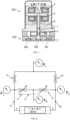
- FIG. 1 shows generally a known arrangement of a flapper and nozzle servo valve.
- the assembly comprises a torque motor subsystem 300 and a flapper-nozzle subsystem 400.
- the assembly comprises a flapper 6 disposed in a flapper cavity 7, a pair of nozzles 9 disposed in a nozzle housing, and an electromagnet 8 surrounding an armature 5.
- the armature has opposed tips, which protrude through gaps in a housing surrounding the electromagnet, and which are arranged to leave spaces between the armature and the housing.
- the electromagnet is connected to an electrical input (not shown) and the armature 5 is connected in a perpendicular manner to the flapper 6, or is an integral part of the flapper - the integral part being perpendicular to the flapper.
- the electromagnet includes coils that surround the armature and a set of permanent magnets that surround the coils.
- the direction of the magnetic flux depends on the sign (direction) of the current.
- the magnetic flux will cause the armature tips to be attracted to the electromagnet (current direction determines which magnetic pole is attracting and which one is repelling) thus varying the size of the spaces.
- This magnetic force creates an applied torque on the flapper, which is proportional to the applied current.
- the flapper rotates and interacts with the nozzles.
- Nozzles 9 are housed within a respective nozzle cavity in the housing, and comprise a fluid outlet and fluid inlet.
- the housing also has a port, which allows communication of fluid to the nozzles.
- the flapper comprises a blocking element at an end thereof which interacts with fluid outlets of nozzles to provide metering of fluid from the fluid outlets to a fluid port in the housing.
- the fluid port in turn allows communication of fluid pressure downstream to a spool valve and actuator arrangement (not shown). The positioning of the flapper between nozzles (controlled by the movement of the armature via electromagnet) will control the amount of fluid pressure communicated to the spool valve and actuator arrangement (not shown), which can be used to control actuator movement.
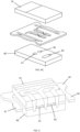
- the flows of pressurised fluid in a conventional flapper type system can also be explained with reference to the simple schematic of Fig. 2 .
- the hydraulic fluid to be regulated by the spool valve for moving the actuator is delivered from a fluid supply with a constant pressure Ps via orifices 10,20. At the orifices, the fluid is divided into two streams. One stream 6,7 is provided to the ends of the valve spool. The other stream is directed to the flapper nozzles 9', 9" where it is used to control movement of the spool due to the position of the flapper 6.
- the servo valve assembly of the present invention comprises an integral flapper and nozzle structure whereby the flapper, orifices and nozzles are formed by a sheet of metal, the integral flapper and nozzle structure being formed into a single component.
- Figs. 3A and 3B show, respectively, the two sides of the integral structure.
- the features of the flapper 15, nozzles 13,14 and orifices 11,12 are formed in a generally rectangular sheet metal structure.
- the orifices 11, 12 are formed in a first area of the sheet and are designed to be fixed in position relative to the other area of the sheet into which the flapper 15 is formed.
- the flapper 15 is formed in the sheet of compliant material such that its position or spacing relative to the nozzles 13,14 can be varied.
- a sheet 50 of flexible material of generally rectangular shape is cut to define two opposing arm portions 51, 52.
- the arms are elastic such that they can move within the plate structure as will be described further below.
- shapes are cut to define two opposing nozzles 61,62 (13, 14 in Fig. 3B ) and two constant orifices 63, 64 (11, 12 in Fig. 3B ) and supply channels 65,66 between the orifices and the nozzles.
- the cutting has to be performed in a highly precise manner e.g. by laser cutting, water-jet cutting, wire-EDM cutting or photoetching.
- a cover plate 70,80 is fixed to either side of the sheet 50.
- One of the cover plates 80 is provided with two output ports 81,82 for piloting channels for the valve spool (not shown) and a single supply port 83 common to the two nozzles 61,62.
- the cover plates 70,80 can be fixed to the metal sheet 50 by any method that ensures strength and tightness of fixation e.g. by electron beam welding.
- a slot 90 is then formed through the sandwich layers as shown in Fig. 6 . This allows a drive member (not shown here) from a torque motor to engage with the flapper for moving the flapper in response to the servo valve control command. It is also possible to locate a feedback spring (not shown) in this slot to provide feedback from the valve spool to the flapper.
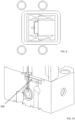
- the next stage involves cutting through the sandwich structure, as shown in Figs. 6B and 6C , along a cutting line 100 to define the flapper 110.
- the cut defining the flapper 110 is made such as to define a precisely calibrated gap 120 between the flapper 110 and the nozzles 61.62. It is critical that the position of the nozzles 61,62 with respect to the flapper 110 is precisely set at this stage.
- the gaps 120 between the flapper and the nozzles may be the same or different for each nozzle but must be precisely set.
- a drive member (not shown) is moved.
- the drive member is engaged with the flapper 110 e.g. by extending through the slot 90. This causes the flapper 110 to move (shown by the arrow) with respect to the rest of the structure containing the nozzles. This movement is enabled by the elasticity of the arms 51,52. The elasticity also biases the flapper 110 to return to the original position when the force of the drive member is removed.
- the gaps between the flapper and the respective nozzles 61,62 change.
- the gap 120 between the flapper and the nozzle 61 increases, while the gap 120' between the flapper and the other nozzle 61 decreases.
- the flapper 110 When assembled into a servo valve assembly, the flapper 110 operates to vary flow between the respective nozzles resulting in a pressure differential that causes movement of the valve spool as previously described for conventional systems.
- Figs. 8 and 9 show how the flapper and nozzle structure 200 can be assembled into the body of a servo-valve assembly between the motor (not shown) and the valve body 300.
- a gasket 130 may be positioned as a seal between the flapper structure and the valve body.
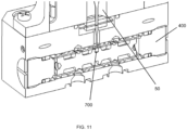
- Figs. 10 and 11 show the flapper and nozzle structure 200 fitted into a servo valve assembly to cause movement of the valve spool 400.
- the drive member can be seen extending from the drive sub-assembly where the motor would be located. This extends through the slot 90 in the flapper and nozzle structure 200 and is drive in response to a control command to move the flapper 110 as described above with reference to Figs. 7A and 7B .
- a spring or feedback wire 700 may also extend through the slot to provide feedback from the valve spool 400.
- the single package structure of this invention integrating the nozzles and orifices and flapper, means that the critical components of the servo valve control structure can all be made precisely and with repeatable accuracy as a single structure. This can then be easily replaced in the valve even during service.
- the structure is simple and cost effective to manufacture and assemble into the valve body.
- the structure can also be easily designed for different performance requirements merely by making different size cuts during manufacture.
Landscapes
- Engineering & Computer Science (AREA)
- General Engineering & Computer Science (AREA)
- Mechanical Engineering (AREA)
- Physics & Mathematics (AREA)
- Fluid Mechanics (AREA)
- Electromagnetism (AREA)
- Servomotors (AREA)
Claims (9)
- Arrangement de servovanne comprenant un corps de tiroir (400), un moteur d'entraînement, un élément d'entraînement se prolongeant à partir du moteur d'entraînement pour commander le mouvement du corps de tiroir, et une structure de clapet et de buse intégrée (200) comprenant un clapet (110), des orifices (63, 64) et des buses (61, 62) formées par une feuille (50) de métal, la structure de clapet et de buse intégrée (200) étant formée en un seul composant, la structure de clapet et de buse intégrée (200) comprenant la feuille (50) de métal flexible découpée pour définir deux parties de bras élastiques flexibles opposées (51, 52) et pourvue, entre les parties de bras, de première et seconde buses opposées (61, 62), de premier et second orifices fixes (63, 64), d'un premier canal (65) entre la première buse et le premier orifice et d'un second canal (66) entre la seconde buse et le second orifice ; moyennant quoi la structure de clapet et de buse intégrée est positionnée de telle sorte que l'élément d'entraînement vient en prise avec le clapet (110) et que le mouvement de l'élément d'entraînement provoque le mouvement du clapet par rapport aux buses en raison de l'élasticité des parties de bras, pour réguler le débit de fluide vers le corps de tiroir pour provoquer le mouvement du corps de tiroir, l'élasticité des parties de bras étant telle qu'elle pousse le clapet à revenir à une position d'origine lorsque la force de l'élément d'entraînement est supprimée.
- Arrangement selon la revendication 1, dans lequel le clapet (110) est formé dans une première zone de la feuille (50) de métal, la feuille étant formée d'un métal souple, et les orifices (63, 64) sont formés dans une seconde zone de la feuille (50) de métal, les première et seconde zones de la feuille (50) étant colocalisées de telle sorte que les orifices (63, 64) sont dans une position spatiale fixe par rapport au clapet (110).
- Arrangement selon la revendication 1 ou 2, la structure de clapet et de buse intégrée (200) comprenant également une première plaque de recouvrement (70) fixée à une première face de la feuille (50) et une seconde plaque de recouvrement (80) fixée à une seconde face opposée de la feuille, l'une des première et seconde plaques de recouvrement étant pourvue d'un premier et d'un second orifices de sortie (81, 82) et d'un orifice d'alimentation unique (83) commun aux première et seconde buses.
- Arrangement selon une quelconque revendication précédente, la structure de clapet et de buse intégrée (200) comprenant également une fente (90) à travers celle-ci agencée pour recevoir l'élément d'entraînement du moteur d'entraînement pour déplacer le clapet.
- Procédé de formation d'un arrangement selon l'une quelconque des revendications 1 à 4, le procédé comprenant la formation, par découpe, du clapet, des buses et des orifices dans la feuille (50) de métal de telle sorte que le clapet soit mobile par rapport aux buses, le procédé comprenant la découpe de la feuille de métal souple (50) pour former les deux parties de bras opposées et pour former, entre les parties de bras, les première et seconde buses, les premier et second orifices et les premier et second canaux reliant respectivement les orifices et les buses.
- Procédé selon la revendication 5, dans lequel la découpe est réalisée par découpe laser, découpe au jet d'eau, découpe par électroérosion à fil ou photogravure.
- Procédé selon la revendication 5 ou 6, comprenant également la fixation de première et seconde plaques de recouvrement respectivement sur des première et seconde faces (70, 80) de la tôle souple, et la formation, dans l'une des plaques de recouvrement, de deux orifices de sortie (81, 82) et d'un orifice d'alimentation unique (83) commun aux première et seconde buses.
- Procédé selon la revendication 5, 6 ou 7, comprenant également la formation d'une fente (90) à travers la structure de clapet et de buse intégrée (200) pour recevoir l'élément d'entraînement du moteur d'entraînement pour provoquer le mouvement du clapet.
- Procédé selon l'une quelconque des revendications 5 à 8, dans lequel le clapet est formé en coupant à travers la structure de clapet et de buse intégrée (200) pour former un espace (120) entre le clapet et les buses.
Priority Applications (5)
| Application Number | Priority Date | Filing Date | Title |
|---|---|---|---|
| EP20461601.5A EP4019787B1 (fr) | 2020-12-22 | 2020-12-22 | Arrangement de servovanne |
| CA3140341A CA3140341A1 (en) | 2020-12-22 | 2021-11-24 | Servo valve flapper and nozzle structure |
| US17/543,923 US11739769B2 (en) | 2020-12-22 | 2021-12-07 | Servo valve flapper and nozzle structure |
| BR102021025452-1A BR102021025452A2 (pt) | 2020-12-22 | 2021-12-16 | Estrutura de aba e bocal integral para uma servoválvula, conjunto de servoválvula, e, método para formar uma estrutura de aba e bocal integral |
| US18/455,950 US12038025B2 (en) | 2020-12-22 | 2023-08-25 | Servo valve flapper and nozzle structure |
Applications Claiming Priority (1)
| Application Number | Priority Date | Filing Date | Title |
|---|---|---|---|
| EP20461601.5A EP4019787B1 (fr) | 2020-12-22 | 2020-12-22 | Arrangement de servovanne |
Publications (2)
| Publication Number | Publication Date |
|---|---|
| EP4019787A1 EP4019787A1 (fr) | 2022-06-29 |
| EP4019787B1 true EP4019787B1 (fr) | 2024-10-30 |
Family
ID=73943288
Family Applications (1)
| Application Number | Title | Priority Date | Filing Date |
|---|---|---|---|
| EP20461601.5A Active EP4019787B1 (fr) | 2020-12-22 | 2020-12-22 | Arrangement de servovanne |
Country Status (4)
| Country | Link |
|---|---|
| US (2) | US11739769B2 (fr) |
| EP (1) | EP4019787B1 (fr) |
| BR (1) | BR102021025452A2 (fr) |
| CA (1) | CA3140341A1 (fr) |
Families Citing this family (1)
| Publication number | Priority date | Publication date | Assignee | Title |
|---|---|---|---|---|
| EP4019787B1 (fr) | 2020-12-22 | 2024-10-30 | Hamilton Sundstrand Corporation | Arrangement de servovanne |
Family Cites Families (11)
| Publication number | Priority date | Publication date | Assignee | Title |
|---|---|---|---|---|
| US4150686A (en) | 1976-11-15 | 1979-04-24 | Textron Inc. | Electrohydraulic control module |
| GB2104249B (en) | 1981-08-19 | 1985-05-15 | Moog Inc | Servovalves |
| FR2689598B1 (fr) * | 1992-04-01 | 1994-05-27 | Univ Toulouse | Dispositif de modulation d'energie d'un distributeur de fluide, et modulateurs d'energie equipes d'un tel dispositif. |
| US20030173311A1 (en) | 2002-01-23 | 2003-09-18 | Bob Younger | Servo sandwich filter assembly |
| US20090321667A1 (en) | 2008-06-25 | 2009-12-31 | Honeywell International Inc. | Servo valve modules and torque motor assemblies |
| EP2812585A1 (fr) | 2012-02-09 | 2014-12-17 | Moog Inc. | Servo-valve électrohydraulique |
| EP2817520B1 (fr) | 2012-02-23 | 2019-01-09 | Moog Inc. | Vanne électro-hydraulique à structure intégrée |
| EP3205913B1 (fr) | 2016-02-11 | 2019-07-03 | Hamilton Sundstrand Corporation | Buse avec ajustement serré modifiable |
| EP3217020B1 (fr) | 2016-03-10 | 2020-04-29 | Hamilton Sundstrand Corporation | Clapet et ensemble armature/clapet destiné à être utilisé dans une servovanne |
| EP3715683B1 (fr) | 2019-03-29 | 2022-05-04 | Hamilton Sundstrand Corporation | Servovanne à tiroir |
| EP4019787B1 (fr) | 2020-12-22 | 2024-10-30 | Hamilton Sundstrand Corporation | Arrangement de servovanne |
-
2020
- 2020-12-22 EP EP20461601.5A patent/EP4019787B1/fr active Active
-
2021
- 2021-11-24 CA CA3140341A patent/CA3140341A1/en active Pending
- 2021-12-07 US US17/543,923 patent/US11739769B2/en active Active
- 2021-12-16 BR BR102021025452-1A patent/BR102021025452A2/pt unknown
-
2023
- 2023-08-25 US US18/455,950 patent/US12038025B2/en active Active
Also Published As
| Publication number | Publication date |
|---|---|
| US20220196040A1 (en) | 2022-06-23 |
| US20230400042A1 (en) | 2023-12-14 |
| US11739769B2 (en) | 2023-08-29 |
| US12038025B2 (en) | 2024-07-16 |
| CA3140341A1 (en) | 2022-06-22 |
| EP4019787A1 (fr) | 2022-06-29 |
| BR102021025452A2 (pt) | 2022-07-05 |
Similar Documents
| Publication | Publication Date | Title |
|---|---|---|
| EP3901473B1 (fr) | Servovanne | |
| US12038025B2 (en) | Servo valve flapper and nozzle structure | |
| EP3660368B1 (fr) | Servovanne | |
| EP3715683B1 (fr) | Servovanne à tiroir | |
| CA2918559A1 (fr) | Ameliorations apportees a des servovalves hydrauliques | |
| EP3715644B1 (fr) | Servovanne de bobine | |
| US11852174B1 (en) | Filter assembly for a servovalve | |
| EP3875783B1 (fr) | Servovanne | |
| US12215791B2 (en) | Flapper servo valve | |
| US12460739B2 (en) | Servovalve | |
| EP3614027B1 (fr) | Servovanne hydraulique | |
| US11506300B2 (en) | Servo valve | |
| US12448990B2 (en) | Two-stage servo valve | |
| EP3597937B1 (fr) | Servovanne | |
| US12486915B2 (en) | Single stage servo valve assembly | |
| US12612977B2 (en) | Single stage servo valve assembly | |
| US11050333B2 (en) | Torque motor assembly |
Legal Events
| Date | Code | Title | Description |
|---|---|---|---|
| PUAI | Public reference made under article 153(3) epc to a published international application that has entered the european phase |
Free format text: ORIGINAL CODE: 0009012 |
|
| STAA | Information on the status of an ep patent application or granted ep patent |
Free format text: STATUS: THE APPLICATION HAS BEEN PUBLISHED |
|
| AK | Designated contracting states |
Kind code of ref document: A1 Designated state(s): AL AT BE BG CH CY CZ DE DK EE ES FI FR GB GR HR HU IE IS IT LI LT LU LV MC MK MT NL NO PL PT RO RS SE SI SK SM TR |
|
| STAA | Information on the status of an ep patent application or granted ep patent |
Free format text: STATUS: REQUEST FOR EXAMINATION WAS MADE |
|
| 17P | Request for examination filed |
Effective date: 20221228 |
|
| RBV | Designated contracting states (corrected) |
Designated state(s): AL AT BE BG CH CY CZ DE DK EE ES FI FR GB GR HR HU IE IS IT LI LT LU LV MC MK MT NL NO PL PT RO RS SE SI SK SM TR |
|
| STAA | Information on the status of an ep patent application or granted ep patent |
Free format text: STATUS: EXAMINATION IS IN PROGRESS |
|
| 17Q | First examination report despatched |
Effective date: 20230725 |
|
| GRAP | Despatch of communication of intention to grant a patent |
Free format text: ORIGINAL CODE: EPIDOSNIGR1 |
|
| STAA | Information on the status of an ep patent application or granted ep patent |
Free format text: STATUS: GRANT OF PATENT IS INTENDED |
|
| INTG | Intention to grant announced |
Effective date: 20240527 |
|
| RAP1 | Party data changed (applicant data changed or rights of an application transferred) |
Owner name: HAMILTON SUNDSTRAND CORPORATION |
|
| GRAS | Grant fee paid |
Free format text: ORIGINAL CODE: EPIDOSNIGR3 |
|
| GRAA | (expected) grant |
Free format text: ORIGINAL CODE: 0009210 |
|
| STAA | Information on the status of an ep patent application or granted ep patent |
Free format text: STATUS: THE PATENT HAS BEEN GRANTED |
|
| AK | Designated contracting states |
Kind code of ref document: B1 Designated state(s): AL AT BE BG CH CY CZ DE DK EE ES FI FR GB GR HR HU IE IS IT LI LT LU LV MC MK MT NL NO PL PT RO RS SE SI SK SM TR |
|
| REG | Reference to a national code |
Ref country code: GB Ref legal event code: FG4D |
|
| REG | Reference to a national code |
Ref country code: CH Ref legal event code: EP |
|
| REG | Reference to a national code |
Ref country code: IE Ref legal event code: FG4D |
|
| REG | Reference to a national code |
Ref country code: DE Ref legal event code: R096 Ref document number: 602020040246 Country of ref document: DE |
|
| REG | Reference to a national code |
Ref country code: LT Ref legal event code: MG9D |
|
| REG | Reference to a national code |
Ref country code: NL Ref legal event code: MP Effective date: 20241030 |
|
| PG25 | Lapsed in a contracting state [announced via postgrant information from national office to epo] |
Ref country code: HR Free format text: LAPSE BECAUSE OF FAILURE TO SUBMIT A TRANSLATION OF THE DESCRIPTION OR TO PAY THE FEE WITHIN THE PRESCRIBED TIME-LIMIT Effective date: 20241030 Ref country code: IS Free format text: LAPSE BECAUSE OF FAILURE TO SUBMIT A TRANSLATION OF THE DESCRIPTION OR TO PAY THE FEE WITHIN THE PRESCRIBED TIME-LIMIT Effective date: 20250228 Ref country code: PT Free format text: LAPSE BECAUSE OF FAILURE TO SUBMIT A TRANSLATION OF THE DESCRIPTION OR TO PAY THE FEE WITHIN THE PRESCRIBED TIME-LIMIT Effective date: 20250228 |
|
| PG25 | Lapsed in a contracting state [announced via postgrant information from national office to epo] |
Ref country code: NL Free format text: LAPSE BECAUSE OF FAILURE TO SUBMIT A TRANSLATION OF THE DESCRIPTION OR TO PAY THE FEE WITHIN THE PRESCRIBED TIME-LIMIT Effective date: 20241030 Ref country code: FI Free format text: LAPSE BECAUSE OF FAILURE TO SUBMIT A TRANSLATION OF THE DESCRIPTION OR TO PAY THE FEE WITHIN THE PRESCRIBED TIME-LIMIT Effective date: 20241030 |
|
| REG | Reference to a national code |
Ref country code: AT Ref legal event code: MK05 Ref document number: 1737118 Country of ref document: AT Kind code of ref document: T Effective date: 20241030 |
|
| PG25 | Lapsed in a contracting state [announced via postgrant information from national office to epo] |
Ref country code: BG Free format text: LAPSE BECAUSE OF FAILURE TO SUBMIT A TRANSLATION OF THE DESCRIPTION OR TO PAY THE FEE WITHIN THE PRESCRIBED TIME-LIMIT Effective date: 20241030 |
|
| PG25 | Lapsed in a contracting state [announced via postgrant information from national office to epo] |
Ref country code: ES Free format text: LAPSE BECAUSE OF FAILURE TO SUBMIT A TRANSLATION OF THE DESCRIPTION OR TO PAY THE FEE WITHIN THE PRESCRIBED TIME-LIMIT Effective date: 20241030 |
|
| PG25 | Lapsed in a contracting state [announced via postgrant information from national office to epo] |
Ref country code: NO Free format text: LAPSE BECAUSE OF FAILURE TO SUBMIT A TRANSLATION OF THE DESCRIPTION OR TO PAY THE FEE WITHIN THE PRESCRIBED TIME-LIMIT Effective date: 20250130 |
|
| PG25 | Lapsed in a contracting state [announced via postgrant information from national office to epo] |
Ref country code: LV Free format text: LAPSE BECAUSE OF FAILURE TO SUBMIT A TRANSLATION OF THE DESCRIPTION OR TO PAY THE FEE WITHIN THE PRESCRIBED TIME-LIMIT Effective date: 20241030 Ref country code: AT Free format text: LAPSE BECAUSE OF FAILURE TO SUBMIT A TRANSLATION OF THE DESCRIPTION OR TO PAY THE FEE WITHIN THE PRESCRIBED TIME-LIMIT Effective date: 20241030 Ref country code: GR Free format text: LAPSE BECAUSE OF FAILURE TO SUBMIT A TRANSLATION OF THE DESCRIPTION OR TO PAY THE FEE WITHIN THE PRESCRIBED TIME-LIMIT Effective date: 20250131 |
|
| PG25 | Lapsed in a contracting state [announced via postgrant information from national office to epo] |
Ref country code: PL Free format text: LAPSE BECAUSE OF FAILURE TO SUBMIT A TRANSLATION OF THE DESCRIPTION OR TO PAY THE FEE WITHIN THE PRESCRIBED TIME-LIMIT Effective date: 20241030 |
|
| PG25 | Lapsed in a contracting state [announced via postgrant information from national office to epo] |
Ref country code: RS Free format text: LAPSE BECAUSE OF FAILURE TO SUBMIT A TRANSLATION OF THE DESCRIPTION OR TO PAY THE FEE WITHIN THE PRESCRIBED TIME-LIMIT Effective date: 20250130 |
|
| PG25 | Lapsed in a contracting state [announced via postgrant information from national office to epo] |
Ref country code: SM Free format text: LAPSE BECAUSE OF FAILURE TO SUBMIT A TRANSLATION OF THE DESCRIPTION OR TO PAY THE FEE WITHIN THE PRESCRIBED TIME-LIMIT Effective date: 20241030 |
|
| PG25 | Lapsed in a contracting state [announced via postgrant information from national office to epo] |
Ref country code: MC Free format text: LAPSE BECAUSE OF FAILURE TO SUBMIT A TRANSLATION OF THE DESCRIPTION OR TO PAY THE FEE WITHIN THE PRESCRIBED TIME-LIMIT Effective date: 20241030 |
|
| PG25 | Lapsed in a contracting state [announced via postgrant information from national office to epo] |
Ref country code: DK Free format text: LAPSE BECAUSE OF FAILURE TO SUBMIT A TRANSLATION OF THE DESCRIPTION OR TO PAY THE FEE WITHIN THE PRESCRIBED TIME-LIMIT Effective date: 20241030 |
|
| PG25 | Lapsed in a contracting state [announced via postgrant information from national office to epo] |
Ref country code: EE Free format text: LAPSE BECAUSE OF FAILURE TO SUBMIT A TRANSLATION OF THE DESCRIPTION OR TO PAY THE FEE WITHIN THE PRESCRIBED TIME-LIMIT Effective date: 20241030 |
|
| PG25 | Lapsed in a contracting state [announced via postgrant information from national office to epo] |
Ref country code: RO Free format text: LAPSE BECAUSE OF FAILURE TO SUBMIT A TRANSLATION OF THE DESCRIPTION OR TO PAY THE FEE WITHIN THE PRESCRIBED TIME-LIMIT Effective date: 20241030 |
|
| PG25 | Lapsed in a contracting state [announced via postgrant information from national office to epo] |
Ref country code: SK Free format text: LAPSE BECAUSE OF FAILURE TO SUBMIT A TRANSLATION OF THE DESCRIPTION OR TO PAY THE FEE WITHIN THE PRESCRIBED TIME-LIMIT Effective date: 20241030 |
|
| PG25 | Lapsed in a contracting state [announced via postgrant information from national office to epo] |
Ref country code: CZ Free format text: LAPSE BECAUSE OF FAILURE TO SUBMIT A TRANSLATION OF THE DESCRIPTION OR TO PAY THE FEE WITHIN THE PRESCRIBED TIME-LIMIT Effective date: 20241030 |
|
| REG | Reference to a national code |
Ref country code: CH Ref legal event code: PL Ref country code: DE Ref legal event code: R097 Ref document number: 602020040246 Country of ref document: DE |
|
| PG25 | Lapsed in a contracting state [announced via postgrant information from national office to epo] |
Ref country code: LU Free format text: LAPSE BECAUSE OF NON-PAYMENT OF DUE FEES Effective date: 20241222 |
|
| PLBE | No opposition filed within time limit |
Free format text: ORIGINAL CODE: 0009261 |
|
| STAA | Information on the status of an ep patent application or granted ep patent |
Free format text: STATUS: NO OPPOSITION FILED WITHIN TIME LIMIT |
|
| PG25 | Lapsed in a contracting state [announced via postgrant information from national office to epo] |
Ref country code: SE Free format text: LAPSE BECAUSE OF FAILURE TO SUBMIT A TRANSLATION OF THE DESCRIPTION OR TO PAY THE FEE WITHIN THE PRESCRIBED TIME-LIMIT Effective date: 20241030 |
|
| 26N | No opposition filed |
Effective date: 20250731 |
|
| REG | Reference to a national code |
Ref country code: BE Ref legal event code: MM Effective date: 20241231 |
|
| PG25 | Lapsed in a contracting state [announced via postgrant information from national office to epo] |
Ref country code: BE Free format text: LAPSE BECAUSE OF NON-PAYMENT OF DUE FEES Effective date: 20241231 |
|
| PG25 | Lapsed in a contracting state [announced via postgrant information from national office to epo] |
Ref country code: CH Free format text: LAPSE BECAUSE OF NON-PAYMENT OF DUE FEES Effective date: 20241231 |
|
| PG25 | Lapsed in a contracting state [announced via postgrant information from national office to epo] |
Ref country code: IE Free format text: LAPSE BECAUSE OF NON-PAYMENT OF DUE FEES Effective date: 20241222 |
|
| PGFP | Annual fee paid to national office [announced via postgrant information from national office to epo] |
Ref country code: GB Payment date: 20251229 Year of fee payment: 6 |
|
| PGFP | Annual fee paid to national office [announced via postgrant information from national office to epo] |
Ref country code: IT Payment date: 20251210 Year of fee payment: 6 |
|
| PGFP | Annual fee paid to national office [announced via postgrant information from national office to epo] |
Ref country code: FR Payment date: 20251230 Year of fee payment: 6 |
|
| PGFP | Annual fee paid to national office [announced via postgrant information from national office to epo] |
Ref country code: DE Payment date: 20251231 Year of fee payment: 6 |