EP4019802B1 - Agencement de soupape pour un amortisseur de vibrations - Google Patents
Agencement de soupape pour un amortisseur de vibrations Download PDFInfo
- Publication number
- EP4019802B1 EP4019802B1 EP21206193.1A EP21206193A EP4019802B1 EP 4019802 B1 EP4019802 B1 EP 4019802B1 EP 21206193 A EP21206193 A EP 21206193A EP 4019802 B1 EP4019802 B1 EP 4019802B1
- Authority
- EP
- European Patent Office
- Prior art keywords
- valve
- disc
- disk
- support
- region
- Prior art date
- Legal status (The legal status is an assumption and is not a legal conclusion. Google has not performed a legal analysis and makes no representation as to the accuracy of the status listed.)
- Active
Links
Images







Classifications
-
- F—MECHANICAL ENGINEERING; LIGHTING; HEATING; WEAPONS; BLASTING
- F16—ENGINEERING ELEMENTS AND UNITS; GENERAL MEASURES FOR PRODUCING AND MAINTAINING EFFECTIVE FUNCTIONING OF MACHINES OR INSTALLATIONS; THERMAL INSULATION IN GENERAL
- F16F—SPRINGS; SHOCK-ABSORBERS; MEANS FOR DAMPING VIBRATION
- F16F9/00—Springs, vibration-dampers, shock-absorbers, or similarly-constructed movement-dampers using a fluid or the equivalent as damping medium
- F16F9/32—Details
- F16F9/34—Special valve constructions; Shape or construction of throttling passages
- F16F9/348—Throttling passages in the form of annular discs or other plate-like elements which may or may not have a spring action, operating in opposite directions or singly, e.g. annular discs positioned on top of the valve or piston body
- F16F9/3485—Throttling passages in the form of annular discs or other plate-like elements which may or may not have a spring action, operating in opposite directions or singly, e.g. annular discs positioned on top of the valve or piston body characterised by features of supporting elements intended to guide or limit the movement of the annular discs
- F16F9/3487—Throttling passages in the form of annular discs or other plate-like elements which may or may not have a spring action, operating in opposite directions or singly, e.g. annular discs positioned on top of the valve or piston body characterised by features of supporting elements intended to guide or limit the movement of the annular discs with spacers or spacing rings
-
- F—MECHANICAL ENGINEERING; LIGHTING; HEATING; WEAPONS; BLASTING
- F16—ENGINEERING ELEMENTS AND UNITS; GENERAL MEASURES FOR PRODUCING AND MAINTAINING EFFECTIVE FUNCTIONING OF MACHINES OR INSTALLATIONS; THERMAL INSULATION IN GENERAL
- F16F—SPRINGS; SHOCK-ABSORBERS; MEANS FOR DAMPING VIBRATION
- F16F9/00—Springs, vibration-dampers, shock-absorbers, or similarly-constructed movement-dampers using a fluid or the equivalent as damping medium
- F16F9/32—Details
- F16F9/34—Special valve constructions; Shape or construction of throttling passages
- F16F9/348—Throttling passages in the form of annular discs or other plate-like elements which may or may not have a spring action, operating in opposite directions or singly, e.g. annular discs positioned on top of the valve or piston body
- F16F9/3484—Throttling passages in the form of annular discs or other plate-like elements which may or may not have a spring action, operating in opposite directions or singly, e.g. annular discs positioned on top of the valve or piston body characterised by features of the annular discs per se, singularly or in combination
-
- F—MECHANICAL ENGINEERING; LIGHTING; HEATING; WEAPONS; BLASTING
- F16—ENGINEERING ELEMENTS AND UNITS; GENERAL MEASURES FOR PRODUCING AND MAINTAINING EFFECTIVE FUNCTIONING OF MACHINES OR INSTALLATIONS; THERMAL INSULATION IN GENERAL
- F16F—SPRINGS; SHOCK-ABSORBERS; MEANS FOR DAMPING VIBRATION
- F16F9/00—Springs, vibration-dampers, shock-absorbers, or similarly-constructed movement-dampers using a fluid or the equivalent as damping medium
- F16F9/10—Springs, vibration-dampers, shock-absorbers, or similarly-constructed movement-dampers using a fluid or the equivalent as damping medium using liquid only; using a fluid of which the nature is immaterial
- F16F9/14—Devices with one or more members, e.g. pistons, vanes, moving to and fro in chambers and using throttling effect
- F16F9/16—Devices with one or more members, e.g. pistons, vanes, moving to and fro in chambers and using throttling effect involving only straight-line movement of the effective parts
- F16F9/18—Devices with one or more members, e.g. pistons, vanes, moving to and fro in chambers and using throttling effect involving only straight-line movement of the effective parts with a closed cylinder and a piston separating two or more working spaces therein
-
- F—MECHANICAL ENGINEERING; LIGHTING; HEATING; WEAPONS; BLASTING
- F16—ENGINEERING ELEMENTS AND UNITS; GENERAL MEASURES FOR PRODUCING AND MAINTAINING EFFECTIVE FUNCTIONING OF MACHINES OR INSTALLATIONS; THERMAL INSULATION IN GENERAL
- F16F—SPRINGS; SHOCK-ABSORBERS; MEANS FOR DAMPING VIBRATION
- F16F9/00—Springs, vibration-dampers, shock-absorbers, or similarly-constructed movement-dampers using a fluid or the equivalent as damping medium
- F16F9/32—Details
- F16F9/36—Special sealings, including sealings or guides for piston-rods
- F16F9/369—Sealings for elements other than pistons or piston rods, e.g. valves
-
- F—MECHANICAL ENGINEERING; LIGHTING; HEATING; WEAPONS; BLASTING
- F16—ENGINEERING ELEMENTS AND UNITS; GENERAL MEASURES FOR PRODUCING AND MAINTAINING EFFECTIVE FUNCTIONING OF MACHINES OR INSTALLATIONS; THERMAL INSULATION IN GENERAL
- F16F—SPRINGS; SHOCK-ABSORBERS; MEANS FOR DAMPING VIBRATION
- F16F9/00—Springs, vibration-dampers, shock-absorbers, or similarly-constructed movement-dampers using a fluid or the equivalent as damping medium
- F16F9/32—Details
- F16F9/44—Means on or in the damper for manual or non-automatic adjustment; such means combined with temperature correction
- F16F9/46—Means on or in the damper for manual or non-automatic adjustment; such means combined with temperature correction allowing control from a distance, i.e. location of means for control input being remote from site of valves, e.g. on damper external wall
- F16F9/465—Means on or in the damper for manual or non-automatic adjustment; such means combined with temperature correction allowing control from a distance, i.e. location of means for control input being remote from site of valves, e.g. on damper external wall using servo control, the servo pressure being created by the flow of damping fluid, e.g. controlling pressure in a chamber downstream of a pilot passage
-
- F—MECHANICAL ENGINEERING; LIGHTING; HEATING; WEAPONS; BLASTING
- F16—ENGINEERING ELEMENTS AND UNITS; GENERAL MEASURES FOR PRODUCING AND MAINTAINING EFFECTIVE FUNCTIONING OF MACHINES OR INSTALLATIONS; THERMAL INSULATION IN GENERAL
- F16F—SPRINGS; SHOCK-ABSORBERS; MEANS FOR DAMPING VIBRATION
- F16F9/00—Springs, vibration-dampers, shock-absorbers, or similarly-constructed movement-dampers using a fluid or the equivalent as damping medium
- F16F9/32—Details
- F16F9/44—Means on or in the damper for manual or non-automatic adjustment; such means combined with temperature correction
- F16F9/46—Means on or in the damper for manual or non-automatic adjustment; such means combined with temperature correction allowing control from a distance, i.e. location of means for control input being remote from site of valves, e.g. on damper external wall
- F16F9/466—Throttling control, i.e. regulation of flow passage geometry
-
- F—MECHANICAL ENGINEERING; LIGHTING; HEATING; WEAPONS; BLASTING
- F16—ENGINEERING ELEMENTS AND UNITS; GENERAL MEASURES FOR PRODUCING AND MAINTAINING EFFECTIVE FUNCTIONING OF MACHINES OR INSTALLATIONS; THERMAL INSULATION IN GENERAL
- F16F—SPRINGS; SHOCK-ABSORBERS; MEANS FOR DAMPING VIBRATION
- F16F9/00—Springs, vibration-dampers, shock-absorbers, or similarly-constructed movement-dampers using a fluid or the equivalent as damping medium
- F16F9/32—Details
- F16F9/44—Means on or in the damper for manual or non-automatic adjustment; such means combined with temperature correction
- F16F9/46—Means on or in the damper for manual or non-automatic adjustment; such means combined with temperature correction allowing control from a distance, i.e. location of means for control input being remote from site of valves, e.g. on damper external wall
- F16F9/466—Throttling control, i.e. regulation of flow passage geometry
- F16F9/469—Valves incorporated in the piston
-
- F—MECHANICAL ENGINEERING; LIGHTING; HEATING; WEAPONS; BLASTING
- F16—ENGINEERING ELEMENTS AND UNITS; GENERAL MEASURES FOR PRODUCING AND MAINTAINING EFFECTIVE FUNCTIONING OF MACHINES OR INSTALLATIONS; THERMAL INSULATION IN GENERAL
- F16K—VALVES; TAPS; COCKS; ACTUATING-FLOATS; DEVICES FOR VENTING OR AERATING
- F16K15/00—Check valves
- F16K15/14—Check valves with flexible valve members
- F16K15/148—Check valves with flexible valve members the closure elements being fixed in their centre
-
- F—MECHANICAL ENGINEERING; LIGHTING; HEATING; WEAPONS; BLASTING
- F16—ENGINEERING ELEMENTS AND UNITS; GENERAL MEASURES FOR PRODUCING AND MAINTAINING EFFECTIVE FUNCTIONING OF MACHINES OR INSTALLATIONS; THERMAL INSULATION IN GENERAL
- F16K—VALVES; TAPS; COCKS; ACTUATING-FLOATS; DEVICES FOR VENTING OR AERATING
- F16K27/00—Construction of housing; Use of materials therefor
- F16K27/02—Construction of housing; Use of materials therefor of lift valves
- F16K27/0209—Check valves or pivoted valves
-
- F—MECHANICAL ENGINEERING; LIGHTING; HEATING; WEAPONS; BLASTING
- F16—ENGINEERING ELEMENTS AND UNITS; GENERAL MEASURES FOR PRODUCING AND MAINTAINING EFFECTIVE FUNCTIONING OF MACHINES OR INSTALLATIONS; THERMAL INSULATION IN GENERAL
- F16K—VALVES; TAPS; COCKS; ACTUATING-FLOATS; DEVICES FOR VENTING OR AERATING
- F16K31/00—Actuating devices; Operating means; Releasing devices
- F16K31/12—Actuating devices; Operating means; Releasing devices actuated by fluid
- F16K31/36—Actuating devices; Operating means; Releasing devices actuated by fluid in which fluid from the circuit is constantly supplied to the fluid motor
- F16K31/40—Actuating devices; Operating means; Releasing devices actuated by fluid in which fluid from the circuit is constantly supplied to the fluid motor with electrically-actuated member in the discharge of the motor
- F16K31/402—Actuating devices; Operating means; Releasing devices actuated by fluid in which fluid from the circuit is constantly supplied to the fluid motor with electrically-actuated member in the discharge of the motor acting on a diaphragm
-
- B—PERFORMING OPERATIONS; TRANSPORTING
- B62—LAND VEHICLES FOR TRAVELLING OTHERWISE THAN ON RAILS
- B62K—CYCLES; CYCLE FRAMES; CYCLE STEERING DEVICES; RIDER-OPERATED TERMINAL CONTROLS SPECIALLY ADAPTED FOR CYCLES; CYCLE AXLE SUSPENSIONS; CYCLE SIDECARS, FORECARS, OR THE LIKE
- B62K25/00—Axle suspensions
- B62K25/04—Axle suspensions for mounting axles resiliently on cycle frame or fork
- B62K25/06—Axle suspensions for mounting axles resiliently on cycle frame or fork with telescopic fork, e.g. including auxiliary rocking arms
- B62K25/08—Axle suspensions for mounting axles resiliently on cycle frame or fork with telescopic fork, e.g. including auxiliary rocking arms for front wheel
-
- F—MECHANICAL ENGINEERING; LIGHTING; HEATING; WEAPONS; BLASTING
- F16—ENGINEERING ELEMENTS AND UNITS; GENERAL MEASURES FOR PRODUCING AND MAINTAINING EFFECTIVE FUNCTIONING OF MACHINES OR INSTALLATIONS; THERMAL INSULATION IN GENERAL
- F16F—SPRINGS; SHOCK-ABSORBERS; MEANS FOR DAMPING VIBRATION
- F16F2222/00—Special physical effects, e.g. nature of damping effects
- F16F2222/12—Fluid damping
-
- F—MECHANICAL ENGINEERING; LIGHTING; HEATING; WEAPONS; BLASTING
- F16—ENGINEERING ELEMENTS AND UNITS; GENERAL MEASURES FOR PRODUCING AND MAINTAINING EFFECTIVE FUNCTIONING OF MACHINES OR INSTALLATIONS; THERMAL INSULATION IN GENERAL
- F16F—SPRINGS; SHOCK-ABSORBERS; MEANS FOR DAMPING VIBRATION
- F16F2228/00—Functional characteristics, e.g. variability, frequency-dependence
- F16F2228/06—Stiffness
- F16F2228/066—Variable stiffness
-
- F—MECHANICAL ENGINEERING; LIGHTING; HEATING; WEAPONS; BLASTING
- F16—ENGINEERING ELEMENTS AND UNITS; GENERAL MEASURES FOR PRODUCING AND MAINTAINING EFFECTIVE FUNCTIONING OF MACHINES OR INSTALLATIONS; THERMAL INSULATION IN GENERAL
- F16F—SPRINGS; SHOCK-ABSORBERS; MEANS FOR DAMPING VIBRATION
- F16F2232/00—Nature of movement
- F16F2232/08—Linear
-
- F—MECHANICAL ENGINEERING; LIGHTING; HEATING; WEAPONS; BLASTING
- F16—ENGINEERING ELEMENTS AND UNITS; GENERAL MEASURES FOR PRODUCING AND MAINTAINING EFFECTIVE FUNCTIONING OF MACHINES OR INSTALLATIONS; THERMAL INSULATION IN GENERAL
- F16F—SPRINGS; SHOCK-ABSORBERS; MEANS FOR DAMPING VIBRATION
- F16F2234/00—Shape
- F16F2234/02—Shape cylindrical
Definitions
- the present invention relates to a valve arrangement for a vibration damper according to the preamble of claim 1.
- the invention also relates to a vibration damper according to claim 12 and a vehicle with such a vibration damper according to claim 13.
- the US2016/025 178 A1 is considered the closest prior art and discloses the preamble of claim 1.
- the vibration damper can be, for example, a telescopic spring fork leg of a motorcycle or a shock absorber for a vehicle with more than one track, for example a passenger car.
- the vibration damper can also be provided for use in the industrial sector.
- the valve arrangement can have a pilot valve which acts as a pressure regulator.
- the damping device or the vibration damper usually has two fluid chambers, between which damping fluid is exchanged.
- the fluid chambers are a first chamber or compression chamber and a second chamber or rebound chamber. During the compression process of the damper device, damping fluid flows out of the compression chamber in the direction of the second chamber or rebound chamber.
- damping fluid flows from the rebound stage chamber in the direction of the compression stage chamber, with the damping fluid flowing through the valve arrangement, with the help of which damping work is performed and the vibration amplitudes acting on the damper device are damped.
- the pilot valve can be used to influence the opening behavior of the valve arrangement or pilot-operated valve by building up a control pressure in a pilot chamber, which acts on the valve piston of the main valve or a valve arrangement arranged on the valve piston.
- the damping force changes with the speed of movement of the piston rod on which the valve piston is arranged.
- a valve arrangement with a pilot valve which has become known, which has a disk-shaped valve body which can be brought into contact with two control edges, namely a radially inner control edge 26, which is provided with a through-flow opening, so that damping fluid can flow into an adjacent recess 25 and can act on the valve body up to an area that rests on a radially outer control edge 27.
- the disk-shaped valve body 9 can lift slightly from the radially outer control edge during the compression movement of the vibration damper provided with it, in order to prevent a jerky or abrupt opening of the main valve, but not during the rebound movement acting on the vibration damper.
- the disk-shaped valve body is in a position that is separate from the two control edges and is lifted upwards, and the flow opening between the two openings through which the damping fluid flows is open.
- this known valve arrangement has the disadvantage that the disk-shaped valve body bears against the inner recess of the valve housing with a radially outer area of the valve body.
- the valve body in the form of a valve disk is therefore guided outside in the housing.
- the disc-shaped valve body is subjected to pressure from the top side by the damping fluid. This pressurization leads to the valve body being inclined and tilted relative to the inner recess and therefore assuming an undefined position.
- the present invention is based on the object of providing a valve arrangement which on the one hand eliminates the problem of tilting of the valve disk and on the other hand both during the compression movement and during the rebound movement allows the main valve to open smoothly and evenly.
- a vibration damper is also to be provided which provides a comfortable transition from the compression movement to the rebound movement.
- a vehicle with such a vibration damper is also to be provided.
- the invention has the features specified in patent claim 1 with regard to the valve arrangement. Advantageous configurations of this are described in the further claims.
- the invention has the features specified in patent claim 12 with regard to the vibration damper.
- the invention has the features specified in patent claim 13 .
- the invention provides a valve arrangement for a vibration damper, with a valve housing that has an annular valve seat and is provided for receiving damping fluid, and a valve piston that is arranged in an interior space of the valve housing so that it can be displaced axially relative to the valve seat, and the valve piston has a main valve that has a flexible, circular valve disk that can be brought into detachable contact with a contact surface side on the valve seat, and the valve disk is arranged by means of a guide pin on the valve piston so that it can be moved axially relative to it and is guided radially, and the valve arrangement has an electromagnet an armature for acting on a pilot valve, a flexible support disk being arranged on the contact surface side of the valve disk facing away from the contact surface side of the valve disk, on which flexible support disk the valve disk rests along a partial peripheral region extending in the circumferential direction of the valve disk.
- the support disk is therefore in contact with the valve disk and supports it when pressure is applied or force is applied to the valve disk in the direction of support washer.
- the valve disk rests on the supporting disk only along a partial circumferential region that extends in the circumferential direction of the valve disk, the valve disk has partial regions or segments or surface regions, viewed in the circumferential direction, on which the supporting disk cannot support the valve disk in the opposite direction to the direction of force acting on the valve disk when pressure is applied to the valve disk in the direction of the supporting disk, i.e. in the areas mentioned it cannot absorb any force supporting the valve disk, i.e. cannot build up an abutment force, which causes the valve to deflect disc bends or deforms in these areas not supported by the support disc.
- the application of a damping pressure to the valve disk via the damping fluid means that the valve disk can deform or bend in the area of the sub-areas or segments or surface areas as a result of the force applied by the damping pressure.
- valve disc detaches from the contact with the annular valve seat on which the valve disc lies flat in the unloaded state and as a result the valve disc lifts off the valve seat in areas, resulting in a gap space between the deformed areas of the valve disc and the valve seat and damping fluid can pass through the gap space and damping work is thus performed.
- valve disc of the main valve lies on the annular valve seat over its entire surface, namely until the main piston or Valve piston performs a slight movement in the direction of force of pressurization due to the pressurization of the valve disc or the main piston.
- the solution according to the invention provides a remedy here by influencing the opening behavior of the main valve in such a way that the main valve begins to open, i.e. a volume flow of damping fluid begins to flow through the main valve, at a point in time before a force equilibrium between the pressure force acting on the main valve and the counterforce due to the pilot pressure and any additional spring force components is established - at such a point in time the main valve would open by lifting off the valve seat.
- This volume flow occurs due to the lifting movement of the valve disk from the valve seat in certain areas or in sections in the area of the surfaces of the valve disk that are not supported by the supporting disk.
- the support disk has at least one clearance in the circumferential direction at which the valve disk is not supported by the support disk and the valve disk bends more when pressure is applied in the direction of the support disk in the area of the clearance than in the area of the support disk without clearance.
- the exemption can therefore be an area or surface area or section or segment of the support disk on which it does not rest against the valve disk and the valve disk can therefore bend or deform or bend relative to the support disk and thus a gap space is created between the valve disk and a section or surface area or segment of a sealing surface on which the valve disk rests or can be brought into contact.
- the sealing surface may be the annular valve seat mentioned above or another sealing surface that occurs between the valve disc and another component.
- the valve disk can therefore provide a flow of damping fluid in the area of the clearance even before the forces acting on the main piston lead to a displacement movement of the main piston, which leads to a complete opening of the main valve on the main piston. If the forces acting on the main piston then lead to a displacement movement of the main piston and thus to an opening movement of the main valve provided on the main piston, a flow of damping fluid takes place in the area between the valve disc of the main valve and the valve seat immediately before the main valve is lifted from the valve seat, so that the flow of damping fluid does not begin or start immediately when the main valve is lifted from the valve seat and in this way the above-described overshooting movement of the main piston is avoided.
- the support disk has a circular first area in a plan view with a first diameter, which is smaller than the outer diameter of the valve disk and, starting from the outer circumference of the first area, at least one second area, which has a second diameter or a second extension, extends radially outwards, which extends along a partial area of the circumference of the support disc in the circumferential direction of the support disc.
- the supporting disc has a circular first area. Starting from this first area, at least one second area extends outwards, which has an external dimension on the outer edge, viewed from the center of the support disk, which is larger in absolute terms than the diameter of the first area.
- this support disk can also have an external configuration that deviates from the circular shape, for example, be rectangular, polygonal, oval, ellipsoid or the like.
- a second region or extension then extends outwards from the outer peripheral region of the first region, the outer edge of which has a greater distance to the center or center when viewed from the center or center of the support disc. This second area then has a smaller extent in the outer peripheral direction of the first area than the outer peripheral area of the first area.
- the second region may be, for example, a region extending away from the first region in the shape of a wing or lobe. More than one such second region can be provided on the outer peripheral region of the first region, for example two such second regions which, viewed from the middle or the center of the supporting disc, are opposite one another or are angularly offset from one another.
- the support disk has at least two radially outwardly extending, opposite projections which, viewed from the center of the support disk, have a radial extension that is less than or equal to the outer diameter of the valve disk.
- valve disk resting on the support disk is supported in the region of the first region of the support disk by the first region when a force is applied by damping fluid in the direction of the support disk, and also the regions of the valve disk which are on the projections resting on the support disk are supported by the support disk, whereas those areas of the valve disk which lie outside the first area of the support disk and also do not rest on the projections of the support disk can largely freely deform or bend when a force is applied by damping fluid. These deforming or deflecting areas of the valve disk are then also no longer in contact with a sealing surface on which the non-deflecting areas of the valve disk are still in contact.
- valve disk Due to the fact that the valve disk only lifts off the sealing surface along a partial area of its outer circumference in this way, a volume flow of damping fluid takes place along the areas that lift off from the sealing surface.
- the valve disc thus assumes a configuration similar to a domed spring washer.
- the valve arrangement has at least one bearing disk, on which the supporting disk rests with its side facing away from the valve disk.
- This support disk is stiffer than the valve disk and/or the support disk, so that the support disk is supported by the support disk when pressure is applied to the valve disk in the direction of the support disk.
- the support disk thus absorbs the compressive force which, as a result of the pressure being applied to the valve disk with damping pressure in the direction of the support disk, acts on the valve disk and thus the support disk.
- the support disk also avoids overloading of the valve disk and/or the support disk, since the areas of the valve disk that are not supported by the support disk can only bend or deform when pressure is applied in the direction of the support disk until the bent or deformed areas of the valve disk come into contact with the support disk, which is designed to be rigid.
- the valve disk is designed to be flexible, so that it can easily deform in the area of the release or releases of the support disk when the damping pressure increases and can release a gap space or gaps for the passage of damping fluid.
- the damping pressure acting on the valve disk can have high values, which could lead to a possible overloading of the flexible valve disk.
- valve disk is supported on the support disk via the support disk, with more than one support disk being able to be provided to support the support disk and thus the valve disk, the result is that the valve disk does not deform beyond the predetermined extent when the damping pressure absorbs high values.
- this configuration also avoids any damage to the flexible valve disk caused by high damping pressure.
- valve arrangement has a sleeve body in the form of a piece of pipe which, along a partial region of its longitudinal extension, has a slot forming the wall of the sleeve body with recesses lying opposite one another, and cylindrical tube segments which are adjacent to the recesses and extend away from a bottom of the sleeve body and run in the longitudinal direction of the sleeve body.
- the sleeve body thus has a configuration in the form of a tubular piece with a base on a front end region of the cylindrical tubular piece. Beginning approximately from the region of the bottom or at a distance from the bottom, the cylindrical tubular piece body has two recesses lying opposite one another, which are therefore designed as rectangular recesses in a plan view are, which break through the wall or wall of the pipe section body opposite one another on both sides and, starting from the floor or at a distance from the floor, extend to the opposite front side end region of the pipe section body.
- valve disk and/or the support disk is/are provided with two recesses within the outer circumference, between which a central web is formed, the pipe segments passing through the recesses.
- valve disk with the two recesses can be placed on the sleeve body, so that the central web passes through the two recesses of the sleeve body and the valve disk and/or the support disk is guided in a torsion-proof manner via physical contact between the two pipe segments and inner peripheral areas of the recesses.
- the discs are guided radially by the guide pin.
- This radial guidance ensures that the valve disk and/or the support disk does not cant relative to the guide pin and/or sleeve body when pressure is applied by damping pressure both via the contact surface side and via the contact surface side, but is arranged on the guide pin and/or sleeve body so that it can move axially, but is guided radially and does not assume an inclined position relative to a longitudinal axis of the sleeve body that would lead to canting.
- the support disk and/or the bearing disk also does not tilt relative to the longitudinal axis of the sleeve body when pressure is applied accordingly.
- both the valve disk and the support disk as well as the bearing disk are guided radially on the sleeve body and can neither cant nor tilt relative to the longitudinal axis of the sleeve body, so that the risk of the valve disk and/or the support disk being inclined relative to the longitudinal axis of the sleeve body when pressure is applied is avoided.
- the pilot valve has a sealing body provided with an outer cone, which can be brought into contact with an annular valve seat of a discharge valve by means of a spring.
- the sealing body can be brought into contact with the annular valve seat of the discharge valve when the electromagnet is in a de-energized position.
- a Woodruff key is provided, which presses the sealing body onto the ring-shaped valve seat.
- valve body can be moved against the action of the disc spring into a position that opens the drain valve, so that a fluid flow of damping fluid from the pilot chamber via the drain valve is enabled.
- the pilot valve has a valve disc which, when the electromagnet is not energized, enables a flow of fluid from a pilot chamber of the pilot valve via the valve housing.
- a safety position of the pilot valve can be brought about by means of this configuration become. This is because the outer cone of the sealing body then rests against the annular valve seat of the outflow valve of the pilot valve, so that the outflow of damping fluid via the outflow valve is prevented. In such a position, the damping fluid is then guided in the direction of a valve disk lying against a valve seat, i.e. an emergency valve disk, which is opened by the system pressure of the damping fluid, so that the damping fluid can drain and no system pressure exceeding the predetermined opening pressure of the emergency valve disk can occur.
- an emergency position of the pilot valve and thus of the valve arrangement can be achieved.
- valve disk has an inner recess which has a larger diameter than the support disk arranged below it in the vertical axis direction of the valve arrangement and the edge region of the inner recess lifts off the support disk when pressure is applied with damping fluid in the direction from the interior of the valve housing.
- valve disk has an edge region arranged on the outer diameter, which is lifted off the valve seat in the direction of the inner space when pressure is applied with damping fluid in the direction of the inner space.
- this lifting movement of the valve disk from the valve seat means that damping work is performed long before the valve disk lifts completely from the valve seat due to a high piston rod speed.
- the invention also provides a shock absorber having a tube and a piston rod, the pipe having an interior space configured to receive the damping fluid, and the shock absorber having a valve assembly as discussed above, and the shock absorber having a compression chamber and a rebound chamber, the two chambers having a respective interior space that is physically separated from the valve assembly.
- the valve arrangement according to the invention therefore physically separates the two chambers, but both chambers are fluidically connected to one another via the valve arrangement, ie designed for fluid exchange via the valve arrangement.
- the invention also creates a vehicle with at least one front wheel and at least one rear wheel, the vehicle having a vibration damper that has been described above.
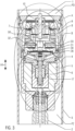
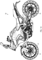
- the drawing shows a sectional view of a telescopic spring fork leg 40 of a motorcycle 80 according to an embodiment of the valve assembly 1.
- the telescopic fork leg 40 has on in the drawing 1 lower end a clamping fist 41 for receiving a quick-release axle 81 of the in 14 the front wheel 82 of the motorcycle 70 shown in the drawing.
- the telescopic spring fork leg 40 is a telescopic spring fork leg designed in an upside-down configuration, in which the compression stage chamber PD is arranged below the valve arrangement 1 in the vertical axis direction H of the telescopic spring fork leg 40 and the rebound stage chamber PZ is arranged above the valve arrangement 1.
- the valve arrangement 1 can also be used in a telescopic spring fork leg, not shown in detail, in which the compression chamber PD is arranged in the vertical axis direction H above the valve arrangement and the rebound chamber PZ is arranged below the valve arrangement 1 .
- the drawing also shows a section II, which is closer based on 2 shown in the drawing.
- the valve arrangement 1 can therefore be used, for example, on a vibration damper 42 designed as a telescopic spring fork leg 40, as is shown in 2 the drawing is shown in more detail.
- the vibration damper 42 has a tube 3 and a piston rod 2 which is arranged in an interior space 43 of the tube 3 together with the valve arrangement 1 .
- the interior space 43 is designed to accommodate a damping fluid, not shown in detail, which is fork oil in the illustrated embodiment.
- the rebound chamber PZ and the compression chamber PD are physically separated from the valve assembly 1 but are fluidically connected via the valve assembly 1 for exchanging fork oil, ie for exchanging damping fluid.
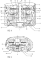
- the valve assembly 1 is supported via a spring 44 on a basis of 1 and 2 abutment 45 shown in the drawing.
- valve assembly 1 shows the valve assembly 1 and other components in a position rotated by 180 degrees compared to the installation position of the valve assembly 1 in the telescopic spring fork leg 40 for ease of illustration and explanation.
- the valve assembly 1 has an annular valve seat 16a and has a valve housing 14 which is adapted to receive damping fluid in the form of the fork oil mentioned above.
- the valve assembly 1 has a valve piston 13 on which a main valve 11 is arranged with valve discs 12, which the basis of 13 visible valve disks 12a, 12b and 12c.
- valve disk 12c or support disk 12c is supported on an annular valve seat 16b which is arranged on an upper side of the valve piston 13 .
- the valve arrangement 1 has a passage 27 which acts as a pre-throttle for the rebound stage and also has a passage 26 which acts as a pre-throttle for the compression stage.
- valve disks 12 are arranged on a guide pin 37, namely guided axially movable relative to the valve piston 13 and radially, for which purpose a closer reference to FIG 13
- the sleeve body 10 shown in the drawing is provided, on which the valve disks 12 are guided radially, so that they cannot cant relative to the longitudinal axis 38 of the guide pin 37 and thus relative to the longitudinal axis 38 of the valve arrangement 1 .
- the valve arrangement 1 also has a plurality of non-return valves 7, 8, 9, 10, which will be discussed below, it being mentioned at this point that the sleeve body 10 also acts as a non-return valve.
- the valve arrangement 1 also has a disk spring 15 which is designed to meander, as can be seen from the illustration 13 can be seen in the drawing.
- valve piston 13 is arranged in an interior space 39 of the valve housing 14 in an axially displaceable manner, and a pilot chamber 25 is also formed in the interior space 39, in which a pilot pressure or pilot pressure can be formed.
- the guide pin 37 is arranged on a stop disk 34 and also accommodates the slotted sleeve body 10 on which the valve disks 12 are guided radially and accommodated in an axially displaceable manner.
- valve housing 14 is radially supported in the tube 3 of the vibration damper 42 via a sealing device 46 and sealed.
- FIG. 5 The drawing shows the pilot valve B with a sealing body 19 which, in the illustrated embodiment, is in the form of a truncated cone in sections and has an outer cone 47 which is pressed by a spring 20 against an annular valve seat 21 of a discharge valve 24 .
- the drawing shows that the pilot valve B has an electromagnet 4, the armature 17 of which can be displaced in the vertical axis direction H1 by applying current, counter to the action of the valve spring 18.
- the pilot valve B has an operating valve 22, which on the basis of Figure 8a can be seen as a passage opening between a supporting edge 48 of a valve seat 30 and the valve spring 18.
- an operating valve 22 When the pilot valve B is in the de-energized position, a fluid flow induced by the system pressure takes place via the operating valve 22.
- the system pressure ensures via the incompressible fork oil that there is an in 12 the. Fluid flow shown in dashed lines occurs because the emergency valve disk 23 can be opened by the system pressure and a predetermined pressure relief can occur.
- a coil 6 is arranged in the visible housing 5, via which the armature 17 of the electromagnet 4 can be energized in such a way that the valve spring or valve disk 18 can be opened against its spring force and in this way, with increasing energization, the operating valve 22 is closed more continuously against the action of the valve spring 18, thereby generating a higher pressure drop.
- the armature 17 When the electromagnet 4 is energized from the de-energized position to a position supplied with a minimum current, the armature 17 generates a thrust force in the direction of the pilot valve B and opens the drain valve 24 against the action of the force of the spring 20, as a result of which the emergency valve formed by the emergency valve disk 23 is short-circuited.
- the valve spring 18 that can be seen has a recess 49 which is provided for the passage of damping fluid (fork oil).
- the valve seat 30 mentioned above is arranged on the valve spring 18 with the interposition of a spacer washer 28 .
- the cover disk 33 is arranged with the interposition of adjusting disks 31 and an O-ring 32 and is supported on a radially inner collar 50 on the spring disk 15 .
- the non-return valves 7, 8 and the non-return valve 9 as well as the sleeve body 10, which also functions as a non-return valve, ensure that the pilot valve B is always supplied with damping fluid from the pressure-generating side and the damping fluid can flow to the side facing away from the pressure, regardless of the direction of movement of the valve arrangement 1, i.e. regardless of whether there is a compression movement or a rebound movement of the vibration damper 2.
- the spring washer 35 shown acts on the check valve 9 and is fixed by a retaining ring 36.
- the inside 4 apparent sleeve body 10 is based on 13 shown in perspective.
- the sleeve body 10 has a tubular configuration with a wall 51, which is formed by a hollow-cylindrical body 52, which is arranged with an end face seated on a circular base 53 and has opposing recesses 54, which are rectangular in plan view and form a respective slot 77.
- the rectangular recesses 54 or slots 77 serve to accommodate a respective central web 55 of the 13 also shown valve disk 12a, the support disk 12b and the two support disks 12c.
- the respective central webs 55 are received in the recesses 54 and are supported via the spring 29 on the bottom 53 of the sleeve body 10 .
- the valve disc 12a has a contact surface side 74, as is the case, for example, with reference to FIG 9 of the drawing and also a support surface side 75 opposite the contact surface side 74, which is also shown in 9 shown in the drawing, with the valve disk 12a resting in some areas with the contact surface side 75 on the support disk 12b arranged underneath.
- the support disk 12b cannot support the valve disk 12a in the area of the clearances 76 of the support disk 12b.
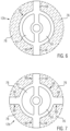
- the exemptions 76 are at the in 6 and 7 the drawing shown support disc 12b dotted line hatched areas shown. In other words, the areas where the support disk 12b does not support the valve disk 12a.
- the wall 51 is in the form of two cylindrical tube segments, which extend away from the base 53 at right angles thereto.
- the two support disks 12c are designed to be rigid and have two recesses 57 which are provided for receiving the tube segments 56 of the sleeve body 10. In addition, damping fluid can also flow through the two recesses 57 .
- the support disk 12b shown is based on two embodiments in 6 and 7 shown enlarged in the drawing.
- the drawing shows a first embodiment of the support disk 12b with two projections 58
- 7 the drawing shows a second embodiment of the support disc 12b with four projections 58.
- the support disk 12b shown in a respective top view has a first region 59 which is circular in a top view and in the illustration shown in FIG 6 two second regions 60 extending radially outwards from the outer circumference of the first region 59, which are designed as projections or wings 58 in the illustrated embodiment.
- the in 7 Support disk 12b shown according to the second embodiment has a first circular area 59, from which four second areas 60 extend radially outwards, each of which is designed as a projection or vane 58.
- the respective first region 59 of the support disk 12b has a smaller outside diameter than the valve disk 12a arranged to rest thereon.
- the support disk 12b also has recesses 61 through which the cylindrical tube segments 56 of the sleeve body 10 pass and which are also designed for the passage of damping fluid.
- valve disc 12a has an edge region 62 on the outer peripheral region which is intended to rest against the annular valve seat 16a of the valve housing 14 and also itself from this to form gap spaces between the valve disc 12a and the valve seat 16a and can also be completely separated from the valve seat 16a when the valve piston 13 is moved axially away from the valve seat 16a, as will be explained in more detail below.
- the drawing shows an enlarged sectional view of the valve assembly 1 to show the fluid flow in the compression stage at low speed of the piston rod 2.
- the motorcycle 80 provided with the valve arrangement 1 according to the invention drives over a bump in the ground with the front wheel 82, this leads to a compression movement of the telescopic spring fork leg 40.
- different piston rod speeds of the piston rod 2 can occur.
- the vibration damper 42 can also be used to dampen movements of the rear wheel 83 of the motorcycle 80 .
- the valve assembly 1 attached to the piston rod 2 moves back and forth within the tube 3 filled with damping fluid in the form of, for example, fork oil.
- the valve arrangement 1 also includes the electromagnet 4 described above and, for example, in 4
- the valve assembly 1 shown has the damping fluid flowing through it during a movement both in the compression direction and in the tension direction.
- the movement in the compression direction occurs when the vibration damper 42, which is designed as a telescopic spring fork leg 40 only for the sake of explanation, experiences a compression movement, while the movement in the tension direction occurs when the vibration damper 42 experiences an extension movement or rebound movement.
- compression stage corresponds to the state that occurs during the compression movement
- the moving rebound stage corresponds to the state that occurs during the rebound movement.
- the pressure drop in both directions of movement can be influenced with the aid of the electromagnet 4 via a corresponding displacement movement of the valve disk 18 .
- part of the oil flow resulting from the respective movement is fed to the pilot valve B, which is acted upon by the electromagnet 4 .
- the system of four check valves 7, 8, 9, 10 already described above makes it possible for the pilot valve B to always be supplied with damping fluid from the pressure-generating side and for the damping fluid to flow away to the side facing away from the pressure.
- the pilot pressure generated by the pilot valve B acts on the rear surface of the main valve 11 and thus influences the pressure drop that occurs at the main valve 11 or the valve arrangement 1 .
- the valve piston 13 is sealed against the valve housing 14 with a hydraulic fit and is thereby radial guided and axially supported.
- the valve piston 13 is pressed against the valve seat 16a in the valve housing 14 by means of the disc spring or spring washer 15 .
- the pilot valve B takes the in 12 the safety position shown in the drawing.
- the outer cone 19 is acted upon by the spring 20 against the valve seat 21 of the discharge valve 24 and an oil flow which is set up flows through the open service valve 22 in the direction of the emergency valve formed by the emergency valve disk 23 .
- Energizing electromagnet 4 with a minimum operating current ensures that armature 17 of electromagnet 4 exerts a thrust force in the direction of pilot valve B, opening drain valve 24 against the force of spring 20 and short-circuiting emergency valve 23.
- the operating valve 22 is still in a wide open position and in this way only generates a small drop in pressure. With increasing energization of the electromagnet 4, the operating valve 22 is closed further and thereby generates a higher pressure drop.
- the drawing shows the flow of damping fluid at a low piston rod speed.
- the flow of damping fluid can be seen from the arrows and the dashed lines.
- the main valve 11 remains closed and there is only a slight flow of oil through the main valve 11 instead of by the recesses 63 of the valve disk 12a, the recesses 61 of the support disk 12b and the recesses 57 of the disks 12c are flown through and the damping fluid passes the restrictor 26 and enters the pilot chamber 25 and from there via the service valve ( Figure 8a ) and the open valve seat 21 and the check valve 9 and the housing 14 in the direction of the rebound chamber PZ.
- the course of the damping force labeled II shows the course of the damping force when the support disk 12b is formed with four projections, as shown in the illustration 7
- the course of the damping force denoted by III shows the course of the damping force when the support disk 12b is formed with two projections 58 as shown in FIG 6 shows.
- the 8 illustrated and denoted by the case 65 further flow of damping fluid. Due to the increase in pressure in the compression chamber PD, a portion of the damping fluid still flows via the recesses 63 of the valve disc 12a, the recesses 61 of the support disc 12b and the recesses 57 of the discs 12c, as described above.
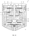
- the recesses 63 of the valve disc 12a have an inner recess in the area of the opposite curved outer peripheral areas, which has a larger diameter than the support disc 12b arranged below it in the vertical axis direction of the valve assembly 1 and the edge area 68 of the inner recess lifts off the support disc 12b when pressure is applied with damping fluid in the direction from the interior 39 of the valve housing 14, as is shown in FIG 10 shown in the drawing.
- the pressure rise in the compression chamber PD also ensures that the edge area 62 of the flexible valve disk 12a is lifted off the valve seat 16a to open a gap space between the edge area 62 and the valve seat 16a.
- the support disk 12b has a circular first area 59, which is smaller than the outer diameter of the valve disk 12a, and the valve disk 12a on the support disk 12b outside of the first area 59 only rests on the projections 58, but these are not present along the entire circumferential extent of the circular first area 59, the valve disk 12a can relative to the support disk 12b at the projections 58 deform from below supported areas similar to a spring washer and in this way forms between the edge portion 62 of the valve disc 12a and the annular Valve seat 16a along a partial peripheral area of the valve disk 12a and an oil flow symbolized by the arrow 65 takes place directly via the channel 64 in the direction of the rebound stage chamber PZ.
- the configuration according to the invention of the valve arrangement 1 with the support disk 12b, which has radially outwardly projecting projections 58, which only partially support the valve disk 12a on the contact side of the valve disk 12a on the support disk 12b, means that the valve disk 12a can open a gap space or gap spaces to the annular valve seat 16a at a time when others in the circumferential direction of the edge region 62 of the valve disk 1 2a running other edge regions, namely those that are supported or supported by the projections 58 of the support disk 12b, still rest on the valve seat 16a.
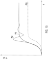
- the drawing shows a diagram to explain the course of the volume flow of damping fluid and the pressure course plotted against time.
- the pressure profile denoted by P1 occurs as a result of the volume flow of damping fluid through the valve arrangement 1, denoted by Q1.
- the oscillating pressure profile is eliminated, as is the loss of comfort associated with the known valve assembly.
- valve disks 12 of the main valve i.e. the valve disk 12a, the support disk 12b and the bearing disks 12c, are completely released from the valve seat 16a, as is shown in Fig 9 shown in the drawing.
- the counterforce on the back of the main valve 11 is determined by the pressure-loaded area of the valve piston 13 multiplied by the pressure that is built up by the pilot valve B and the force of the spring 15.
- the flexible valve disk 12a can release a passage cross section at the annular valve seat 16a depending on the pressure, even if the main valve 11 is not yet fully open, since the above-described equilibrium of forces has not yet been reached.
- This configuration ensures a constant opening behavior of the main valve 11 according to the curve II, III in 16 according to segment "B".
- the piston rod 2, on which the valve arrangement 1 is arranged moves out out of the area of the compression chamber PD in the direction of the rebound chamber PZ. This movement leads to an increase in the system pressure in the rebound chamber and thus to a flow of oil in the direction of the compression chamber.
- the drawing shows an enlarged sectional view of the valve assembly 1 to show the fluid flow in the rebound at low and medium speed of the piston rod, which occurs during the rebound movement.
- the main valve 11 remains closed with the valve discs 12 and an oil flow takes place via the pilot valve B, which in turn corresponds to the curve according to segment "A". 16 .
- Damping fluid flows from the rebound chamber via the restrictor 27 of the main valve 11 and the check valve 7, which opens due to the system pressure, into the pilot chamber 25 of the pilot valve B and from there via the pilot valve B and the housing 14 or the oil channel 66 and the recesses 57, 61 and 63 (see Fig 13 ), towards the compression chamber PD.
- the sleeve body 10 is designed in such a way that it holds the valve disc 12a and the support disc 12b and the stop discs 12c in a mutually aligned position. This is achieved in that the sleeve body 10 with its cylindrical tube segments 56 passes through the respective recesses 57, 61 and 63 of the disks 12a, 12b, 12c and thus ensures that the disks are arranged such that they cannot rotate relative to one another.
- the cross-sectional area of the respective recesses 57, 61 and 63 of the stacked discs thus remains constant and it is avoided that central webs 55 of the discs 12a, 12b, 12c can twist relative to one another, which would lead to a change in the cross-sectional area through which flow can take place.
- the predetermined effective flow cross section formed by the recesses is thus retained in a predetermined manner.
- This function of the sleeve body 10 would also be retained in the case of a possible embodiment of the support disk 12b as a full-surface disk without any cut-outs.
- the increase in system pressure leads to a lifting movement of the radially inner area 69 of the valve disk 12a from the supporting disk 12b, since the system pressure can penetrate into the intermediate space 70 between the underside of the valve disk 12a and the upper side of the first underlying supporting disk 12c, since this intermediate space is not closed by the outer peripheral area of the supporting disk 12b, since this is not formed over the entire surface in this area, but has gaps 76 and the valve disk 12a at the Top of the support disc 12b rests only in the area of the projections 58.
- the resulting oil flow 71 allows the system pressure to relax and a sudden or abrupt or jerky lifting of the valve disks 12 (ie the valve disk 12a, support disk 12b, bearing disks 12c) from the annular valve seat 16a is avoided.
- the second or lower thrust washer 12c still abuts the annular valve seat 16b, as illustrated in FIG 10 can be seen in the drawing.
- valve disc 12a continues to abut annular valve seat 16a.
- the increasing system pressure leads to the main valve 11 opening, since the counterforce acting on the back of the valve piston 13 is exceeded and the annular valve seat 16b opens, since the valve piston 13 detaches with its control edge 72 from the support disk 12c and thus releases the gap space which allows damping fluid to pass through in accordance with the arrow 73 11 the drawing leads.
- the counterforce acting on the valve piston 13 is determined from the pressure-loaded area of the rear side of the valve piston 13 multiplied by the pressure that is built up by the pilot valve B and the pretensioning force of the Woodruff key 15.
- the gap space between the control edge 72 and the bearing disk 12c opens and oil flow can take place through the recesses 57, 61 and 63 in the bearing disks 12c, support disk 12b and the valve disk 12a, as illustrated by the oil flow arrow 73 11 shown in the drawing.
- the valve arrangement according to the invention can therefore also release the passage cross section of the main valve 11 during the rebound movement depending on the system pressure, even if the main valve 11 has not yet lifted off the annular valve seat 16 .
- This also contributes to a constant opening behavior of the main valve in the area of segment "B" during the rebound movement, i.e. at medium damper speeds or piston rod speeds, and the course of the damper force plotted against the damper speed can be influenced by the design of the support disk 12b with two or more projections 58.
- the configuration of the support disk 12b with two projections or wings 58 leads to a more linear curve III of the damping force plotted against the damper speed in the range of medium piston rod speeds, while the design of the support disk 12b with four projections or wings 58 leads to a slightly rounded curve II of the damping force. 16 .
- Drawing shows the course of the damping force over the damper speed with a high current supply to the electromagnet 4 and the course of the respective curves II, III can be changed by changing the current applied to the coil 6 of the electromagnet 4 accordingly.
Landscapes
- Engineering & Computer Science (AREA)
- General Engineering & Computer Science (AREA)
- Mechanical Engineering (AREA)
- Fluid-Damping Devices (AREA)
Claims (13)
- Ensemble formant soupape (1) destiné à un amortisseur de vibrations, comportant un carter de soupape (14) qui présente un siège de soupape (16a) annulaire et est prévu pour recevoir du liquide d'amortissement, et un piston de soupape (13) qui est agencé axialement mobile par rapport au siège de soupape (16) dans une chambre intérieure (39) du carter de soupape (14), ledit piston de soupape (13) présentant une soupape principale (11) présentant un disque de soupape (12a) circulaire flexible susceptible de venir en butée contre le siège de soupape (16) de manière amovible par un côté surface d'appui (74), et ledit disque de soupape (12a) étant agencé sur le piston de soupape (13) au moyen d'une broche de guidage (37) en étant axialement mobile par rapport à ce dernier et apte à subir un guidage radial et ledit ensemble formant soupape (1) présentant un électroaimant (4) doté d'une armature (17) permettant de solliciter une soupape pilote (B), caractérisé en ce que, sur le côté surface de support (75) du disque de soupape (12a), qui est opposé au côté surface d'appui (74) du disque de soupape (12a), il est agencé un disque de soutien (12b) flexible conçu de manière que le disque de soupape (12a) repose sur le disque de soutien (12b) flexible le long d'une première partie circonférentielle partielle s'étendant dans le sens circonférentiel du disque de soupape (12a) et que le disque de soupape (12a) est déformable le long d'une deuxième partie circonférentielle partielle s'étendant dans le sens circonférentiel du disque de soupape (12a) sous l'effet d'une pression assurée par le liquide d'amortissement.
- Ensemble formant soupape (1) selon la revendication 1, caractérisé en ce que le disque de soutien (12b) présente au moins une découpe (76) dans le sens circonférentiel, au niveau de laquelle le disque de soupape (12a) est non soutenu par le disque de soutien (12b) et en ce que le disque de soupape (12a) subit une flexion plus forte dans la zone de la découpe (76), en cas de pression exercée en direction du disque de soutien (12b), que dans la zone du disque de soutien (12b) exempte de découpe (76).
- Ensemble formant soupape (1) selon la revendication 1 ou 2, caractérisé en ce que le disque de soutien (12b) présente une première zone (59) de conception circulaire, vue de dessus, qui présente un premier diamètre qui est inférieur au diamètre extérieur du disque de soupape (12a), et en ce qu'au moins une deuxième zone (60) présentant un deuxième diamètre s'étend radialement vers l'extérieur, en partant de la circonférence extérieure de la première zone (59) et s'étend le long d'une zone partielle de la circonférence du disque de soutien (12b) dans le sens circonférentiel du disque de soutien (12b).
- Ensemble formant soupape (1) selon l'une des revendications précédentes, caractérisé en ce que le disque de soutien (12b) présente au moins deux porte-à-faux (58) mutuellement opposés qui s'étendent radialement vers l'extérieur et qui présentent, vus à partir du centre du disque de soutien (12b), une étendue radiale inférieure ou égale au diamètre extérieur du disque de soupape (12a).
- Ensemble formant soupape (1) selon l'une des revendications précédentes, caractérisé en ce que l'ensemble formant soupape (1) présente au moins un disque d'appui (12c) sur lequel repose le disque de soutien (12b) par son côté détourné du disque de soupape (12a).
- Ensemble formant soupape (1) selon l'une des revendications précédentes, caractérisé en ce que l'ensemble formant soupape (1) présente un corps de douille (10) tubulaire présentant, le long d'une zone partielle de son étendue en longueur, une fente (77) formant la paroi (51) du corps de douille (10) et comportant des évidements (54) opposés, et en ce que sont formés des segments de tube (56) cylindriques adjacents aux évidements (54), qui s'étendent à partir d'un fond du corps de douille (10) selon la direction longitudinale du corps de douille (10).
- Ensemble formant soupape selon la revendication 6, caractérisé en ce que le disque de soupape (12a) et/ou le disque de soutien (12b) sont pourvus, sur l'intérieur de leur circonférence extérieure, de deux évidements (63, 61) entre lesquels est formée une traverse centrale (55), lesdits évidements (63, 61) étant pénétrés par les segments de tube (56).
- Ensemble formant soupape (1) selon l'une des revendications précédentes, caractérisé en ce que la soupape pilote (B) présente un corps d'étanchéité (19) doté d'un cône extérieur (47) et qui, sollicité au moyen d'un ressort (20), est susceptible de venir en butée contre un siège de soupape (21) annulaire d'une soupape de drainage (29).
- Ensemble formant soupape (1) selon l'une des revendications précédentes, caractérisé en ce que la soupape pilote (3) présente un disque de soupape (18) qui, à l'état non alimenté de l'électroaimant (4), permet un écoulement de fluide hors d'une chambre pilote (25) de la soupape pilote (B) par le biais du carter de soupape (14).
- Ensemble formant soupape (1) selon l'une des revendications précédentes, caractérisé en ce que le disque de soupape (12a) présente un évidement interne présentant un plus grand diamètre que celui du disque de soutien (12b) situé sous celui-ci, vu selon le sens de l'axe vertical de l'ensemble formant soupape (1), et en ce que la zone de bord (68) de l'évidement interne se relève par rapport au disque de soutien (12b), en cas de sollicitation par une pression de liquide d'amortissement, vers l'extérieur de la chambre intérieure (39) du carter de soupape (14).
- Ensemble formant soupape (1) selon l'une des revendications précédentes, caractérisé en ce que le disque de soupape (12a) présente une zone de bord (62) agencée au niveau du diamètre extérieur qui se relève par rapport au siège de soupape (16), en cas de sollicitation par une pression de liquide d'amortissement, vers l'intérieur de la chambre intérieure (39).
- Amortisseur de vibrations comportant un tube (3) et une tige de piston (2), ledit tube (3) présentant une chambre intérieure (43) destinée à recevoir le liquide d'amortissement, caractérisé par un ensemble formant soupape (1) selon l'une des revendications précédentes, et comportant une chambre d'étage de compression (PD) ainsi qu'une chambre d'étage de traction (PZ), lesdites deux chambres présentant une chambre intérieure respective séparée physiquement de l'ensemble formant soupape (1) mais reliée fluidiquement à celui-ci.
- Véhicule doté d'une roue avant (82) et d'une roue arrière (83), caractérisé par un amortisseur de vibrations (42) selon la revendication 12.
Applications Claiming Priority (1)
| Application Number | Priority Date | Filing Date | Title |
|---|---|---|---|
| DE102020134820.7A DE102020134820A1 (de) | 2020-12-23 | 2020-12-23 | Ventilanordnung für einen Schwingungsdämpfer |
Publications (2)
| Publication Number | Publication Date |
|---|---|
| EP4019802A1 EP4019802A1 (fr) | 2022-06-29 |
| EP4019802B1 true EP4019802B1 (fr) | 2023-07-26 |
Family
ID=78516615
Family Applications (1)
| Application Number | Title | Priority Date | Filing Date |
|---|---|---|---|
| EP21206193.1A Active EP4019802B1 (fr) | 2020-12-23 | 2021-11-03 | Agencement de soupape pour un amortisseur de vibrations |
Country Status (5)
| Country | Link |
|---|---|
| US (1) | US12044284B2 (fr) |
| EP (1) | EP4019802B1 (fr) |
| JP (1) | JP7365390B2 (fr) |
| DE (1) | DE102020134820A1 (fr) |
| ES (1) | ES2961412T3 (fr) |
Cited By (2)
| Publication number | Priority date | Publication date | Assignee | Title |
|---|---|---|---|---|
| DE202024105093U1 (de) | 2024-07-16 | 2024-09-19 | Ktm Ag | Ventilanordnung eines Schwingungsdämpfers und Schwingungsdämpfer damit |
| DE102024002306A1 (de) * | 2024-07-16 | 2026-01-22 | Ktm Ag | Ventilanordnung eines Schwingungsdämpfers und Schwingungsdämpfer damit |
Families Citing this family (6)
| Publication number | Priority date | Publication date | Assignee | Title |
|---|---|---|---|---|
| US11719304B2 (en) | 2020-03-27 | 2023-08-08 | DRiV Automotive Inc. | Damper assembly |
| US11808323B2 (en) * | 2021-02-15 | 2023-11-07 | DRiV Automotive Inc. | Open bleed-base valve |
| JP7723564B2 (ja) * | 2021-10-04 | 2025-08-14 | カヤバ株式会社 | ショックアブソーバ |
| US20240376953A1 (en) * | 2023-05-08 | 2024-11-14 | DRiV Automotive Inc. | Fulcrum and check discs for shock absorber with optimized bleed range and tuneability |
| KR102858438B1 (ko) * | 2023-07-12 | 2025-09-11 | 에이치엘만도 주식회사 | 내장형 전자 제어 밸브 조립체 및 이를 포함하는 전자 제어 댐퍼 |
| CN120667560B (zh) * | 2025-08-22 | 2025-10-28 | 成都裕鸢航空智能制造股份有限公司 | 飞机用双瓣单向阀、双瓣单向阀开闭系统、开闭方法 |
Family Cites Families (41)
| Publication number | Priority date | Publication date | Assignee | Title |
|---|---|---|---|---|
| JPS5818543B2 (ja) * | 1975-05-23 | 1983-04-13 | トキコ株式会社 | カンシヨウキニオケル ゲンスイリヨクハツセイソウチ |
| US4785920A (en) * | 1986-04-16 | 1988-11-22 | Boge Ag | Hydraulic adjustable shock absorber |
| US5316113A (en) * | 1987-11-19 | 1994-05-31 | Atsugi Motor Parts Company Ltd. | Hydraulic shock absorber |
| US4964493A (en) * | 1988-04-06 | 1990-10-23 | Atsugi Motor Parts Company, Limited | Shock absorber with variable damping characteristics depending upon stroke speed |
| US5211420A (en) * | 1988-09-16 | 1993-05-18 | Honda Giken Kogyo Kabushiki Kaisha | Adjustable height suspension mechanism for two-wheeled motor vehicles |
| US5261448A (en) * | 1989-11-16 | 1993-11-16 | Atsugi Unisia Corp. | Vibration mode responsive variable damping force shock absorber with feature of automatic selection of damping mode depending upon vibration mode of vehicular body |
| JP3471438B2 (ja) * | 1993-12-06 | 2003-12-02 | 株式会社ショーワ | 緩衝器のバルブ構造 |
| KR100443884B1 (ko) * | 2000-11-24 | 2004-08-09 | 주식회사 만도 | 쇽 업소버의 극 저속용 피스톤 밸브 |
| JP4840557B2 (ja) * | 2005-04-12 | 2011-12-21 | 日立オートモティブシステムズ株式会社 | 減衰力調整式油圧緩衝器 |
| DE102007005288B4 (de) | 2007-02-02 | 2013-09-12 | Thyssenkrupp Bilstein Gmbh | Hydraulischer Schwingungsdämpfer |
| KR100841928B1 (ko) * | 2007-02-02 | 2008-06-30 | 주식회사 만도 | 감쇠력 가변식 쇽업소버 |
| US20080185246A1 (en) * | 2007-02-02 | 2008-08-07 | Mando Corporation | Damping force variable shock absorber |
| JP2009209960A (ja) * | 2008-02-29 | 2009-09-17 | Hitachi Ltd | 緩衝器 |
| KR101568042B1 (ko) * | 2008-03-31 | 2015-11-10 | 가부시끼가이샤 히다치 세이사꾸쇼 | 감쇠력 조정식 완충기 |
| DE112010005255T5 (de) * | 2010-02-12 | 2013-05-02 | Hitachi Automotive Systems, Ltd. | Fahrzeugaufhängungsvorrichtung |
| JP5924979B2 (ja) * | 2011-05-31 | 2016-05-25 | 日立オートモティブシステムズ株式会社 | 緩衝器 |
| DE102012210685A1 (de) | 2012-06-25 | 2014-01-02 | Zf Friedrichshafen Ag | Verstellbare Dämpfventileinrichtung |
| JP5781479B2 (ja) * | 2012-08-30 | 2015-09-24 | 株式会社ショーワ | 圧力緩衝装置 |
| DE102012019321B4 (de) | 2012-10-02 | 2015-07-02 | Zf Friedrichshafen Ag | Verstellbare Dämpfventileinrichtung |
| JP5952762B2 (ja) * | 2013-03-13 | 2016-07-13 | Kyb株式会社 | 減衰弁 |
| JP5952760B2 (ja) * | 2013-03-13 | 2016-07-13 | Kyb株式会社 | 減衰弁 |
| US9067471B2 (en) * | 2013-03-15 | 2015-06-30 | Tenneco Automotive Operating Company Inc. | Piston assembly with open bleed |
| US9441699B2 (en) * | 2013-05-13 | 2016-09-13 | Tenneco Automotive Operating Company Inc. | Orifice disc for regulating flow in damper |
| JP6188207B2 (ja) * | 2013-07-31 | 2017-08-30 | 日立オートモティブシステムズ株式会社 | シリンダ装置 |
| JP5787961B2 (ja) * | 2013-10-31 | 2015-09-30 | 日立オートモティブシステムズ株式会社 | 緩衝器 |
| US9500251B2 (en) * | 2014-11-25 | 2016-11-22 | Tenneco Automotive Operating Company Inc. | Shock absorber having orifice check disc |
| KR20170078755A (ko) * | 2014-11-25 | 2017-07-07 | 케이와이비 가부시키가이샤 | 감쇠 밸브 및 완충기 |
| JP6505510B2 (ja) * | 2015-06-08 | 2019-04-24 | 株式会社ショーワ | 圧力緩衝装置 |
| KR102482569B1 (ko) * | 2015-09-17 | 2022-12-29 | 에이치엘만도 주식회사 | 쇽업소버 |
| JP6581511B2 (ja) * | 2016-01-05 | 2019-09-25 | Kyb株式会社 | フロントフォーク |
| US9845839B2 (en) * | 2016-02-18 | 2017-12-19 | Tenneco Automotive Operating Company Inc. | Shock absorber having check disc for orifice passage |
| EP3208489B1 (fr) | 2016-02-22 | 2020-04-29 | Öhlins Racing Ab | Agencement de vanne à 2 voies à ouverture souple pour un amortisseur de choc |
| DE102016218376A1 (de) | 2016-09-23 | 2018-03-29 | Zf Friedrichshafen Ag | Dämpfventil für einen Schwingungsdämpfer |
| US10344820B2 (en) * | 2016-10-28 | 2019-07-09 | Mf Ip Holding, Llc | Digressive valve for a damper |
| JP6291633B1 (ja) * | 2017-10-04 | 2018-03-14 | 株式会社ショーワ | 圧力緩衝装置および減衰力発生機構 |
| JP6701242B2 (ja) * | 2018-02-21 | 2020-05-27 | Kyb株式会社 | バルブおよび緩衝器 |
| WO2019239521A1 (fr) | 2018-06-13 | 2019-12-19 | 株式会社ショーワ | Amortisseur de chocs de pression |
| JP6466041B1 (ja) * | 2018-07-31 | 2019-02-06 | 株式会社ショーワ | 弁機構および緩衝器 |
| CN111536186B (zh) * | 2019-05-06 | 2021-07-23 | 北京京西重工有限公司 | 阻尼器组件和用于阻尼器组件的活塞 |
| JP7402017B2 (ja) * | 2019-11-06 | 2023-12-20 | カヤバ株式会社 | バルブ及び緩衝器 |
| US11719304B2 (en) * | 2020-03-27 | 2023-08-08 | DRiV Automotive Inc. | Damper assembly |
-
2020
- 2020-12-23 DE DE102020134820.7A patent/DE102020134820A1/de not_active Ceased
-
2021
- 2021-11-03 EP EP21206193.1A patent/EP4019802B1/fr active Active
- 2021-11-03 ES ES21206193T patent/ES2961412T3/es active Active
- 2021-12-13 JP JP2021202025A patent/JP7365390B2/ja active Active
- 2021-12-16 US US17/552,563 patent/US12044284B2/en active Active
Cited By (3)
| Publication number | Priority date | Publication date | Assignee | Title |
|---|---|---|---|---|
| DE202024105093U1 (de) | 2024-07-16 | 2024-09-19 | Ktm Ag | Ventilanordnung eines Schwingungsdämpfers und Schwingungsdämpfer damit |
| DE102024002306A1 (de) * | 2024-07-16 | 2026-01-22 | Ktm Ag | Ventilanordnung eines Schwingungsdämpfers und Schwingungsdämpfer damit |
| WO2026017279A1 (fr) | 2024-07-16 | 2026-01-22 | Ktm Ag | Ensemble soupape d'un amortisseur de vibrations et amortisseur de vibrations équipé d'un tel ensemble |
Also Published As
| Publication number | Publication date |
|---|---|
| DE102020134820A1 (de) | 2022-06-23 |
| ES2961412T3 (es) | 2024-03-11 |
| JP2022101492A (ja) | 2022-07-06 |
| JP7365390B2 (ja) | 2023-10-19 |
| US20220196106A1 (en) | 2022-06-23 |
| EP4019802A1 (fr) | 2022-06-29 |
| US12044284B2 (en) | 2024-07-23 |
Similar Documents
| Publication | Publication Date | Title |
|---|---|---|
| EP4019802B1 (fr) | Agencement de soupape pour un amortisseur de vibrations | |
| DE3932669C2 (de) | Hydraulischer Stoßdämpfer | |
| EP3212958B1 (fr) | Procédé pour faire fonctionner un amortisseur de vibrations réglable destiné à des véhicules automobiles | |
| EP0602121B1 (fr) | Dispositif a soupape pilotable pour amortisseurs de vibrations bitubes reglables | |
| DE4019221C2 (de) | Stoßdämpfer mit variabler Dämpfungskraft | |
| EP1788276B1 (fr) | Amortisseur de vibrations avec une force d'amortissement dépendant de l'amplitude | |
| EP0400395B1 (fr) | Amortisseur de choc | |
| EP1767810B1 (fr) | Dispositf de valve d'amortisseur ayant une évolution progressive de la force d'amortissement | |
| WO2017202647A1 (fr) | Amortisseur de vibrations sélectif en fréquence pour des véhicules à moteur comprenant une soupape de commande de dérivation | |
| EP2746615B1 (fr) | Ensemble de soupapes d'amortissement pour un amortisseur d'oscillations semi-actif | |
| DE69023793T2 (de) | Druckregelventil. | |
| EP1629336A1 (fr) | Soupape | |
| EP3464933B1 (fr) | Amortisseur de vibrations sélectif en fréquence pour des véhicules à moteur comprenant une soupape de commande de dérivation | |
| DE102016217112B4 (de) | Frequenzabhängige Dämpfventilanordnung | |
| EP0504624A2 (fr) | Amortisseur de choc | |
| DE102016200935A1 (de) | Schwingungsdämpfer mit frequenzabhängig arbeitender Ventilanordnung | |
| WO2008006659A1 (fr) | Bloc soupape | |
| DE102005052755A1 (de) | Hydraulisch betätigte Klemmeinheit und damit ausgeführte hydraulische Regelachse | |
| DE112020000941T5 (de) | Stossdämpfer | |
| EP1657470B1 (fr) | Elément ressort hydropneumatique pour véhicule automobile, particulièrement pour véhicule à chenilles | |
| WO2018046194A1 (fr) | Ensemble soupape d'amortissement dépendant de la fréquence | |
| EP1034108A1 (fr) | Direction assistee hydraulique | |
| DE3630454C1 (en) | Device for controlling hydraulic drives | |
| EP0616146A1 (fr) | Assemblage de clapet amortisseur | |
| DE3729187A1 (de) | Verstellbare daempfung |
Legal Events
| Date | Code | Title | Description |
|---|---|---|---|
| PUAI | Public reference made under article 153(3) epc to a published international application that has entered the european phase |
Free format text: ORIGINAL CODE: 0009012 |
|
| STAA | Information on the status of an ep patent application or granted ep patent |
Free format text: STATUS: REQUEST FOR EXAMINATION WAS MADE |
|
| 17P | Request for examination filed |
Effective date: 20211109 |
|
| AK | Designated contracting states |
Kind code of ref document: A1 Designated state(s): AL AT BE BG CH CY CZ DE DK EE ES FI FR GB GR HR HU IE IS IT LI LT LU LV MC MK MT NL NO PL PT RO RS SE SI SK SM TR |
|
| GRAP | Despatch of communication of intention to grant a patent |
Free format text: ORIGINAL CODE: EPIDOSNIGR1 |
|
| STAA | Information on the status of an ep patent application or granted ep patent |
Free format text: STATUS: GRANT OF PATENT IS INTENDED |
|
| INTG | Intention to grant announced |
Effective date: 20230224 |
|
| GRAJ | Information related to disapproval of communication of intention to grant by the applicant or resumption of examination proceedings by the epo deleted |
Free format text: ORIGINAL CODE: EPIDOSDIGR1 |
|
| STAA | Information on the status of an ep patent application or granted ep patent |
Free format text: STATUS: REQUEST FOR EXAMINATION WAS MADE |
|
| INTC | Intention to grant announced (deleted) | ||
| GRAP | Despatch of communication of intention to grant a patent |
Free format text: ORIGINAL CODE: EPIDOSNIGR1 |
|
| STAA | Information on the status of an ep patent application or granted ep patent |
Free format text: STATUS: GRANT OF PATENT IS INTENDED |
|
| INTG | Intention to grant announced |
Effective date: 20230516 |
|
| GRAS | Grant fee paid |
Free format text: ORIGINAL CODE: EPIDOSNIGR3 |
|
| P01 | Opt-out of the competence of the unified patent court (upc) registered |
Effective date: 20230514 |
|
| GRAA | (expected) grant |
Free format text: ORIGINAL CODE: 0009210 |
|
| STAA | Information on the status of an ep patent application or granted ep patent |
Free format text: STATUS: THE PATENT HAS BEEN GRANTED |
|
| AK | Designated contracting states |
Kind code of ref document: B1 Designated state(s): AL AT BE BG CH CY CZ DE DK EE ES FI FR GB GR HR HU IE IS IT LI LT LU LV MC MK MT NL NO PL PT RO RS SE SI SK SM TR |
|
| REG | Reference to a national code |
Ref country code: CH Ref legal event code: EP |
|
| REG | Reference to a national code |
Ref country code: IE Ref legal event code: FG4D Free format text: LANGUAGE OF EP DOCUMENT: GERMAN |
|
| REG | Reference to a national code |
Ref country code: DE Ref legal event code: R096 Ref document number: 502021001085 Country of ref document: DE |
|
| REG | Reference to a national code |
Ref country code: SE Ref legal event code: TRGR |
|
| REG | Reference to a national code |
Ref country code: NL Ref legal event code: FP |
|
| REG | Reference to a national code |
Ref country code: LT Ref legal event code: MG9D |
|
| PG25 | Lapsed in a contracting state [announced via postgrant information from national office to epo] |
Ref country code: GR Free format text: LAPSE BECAUSE OF FAILURE TO SUBMIT A TRANSLATION OF THE DESCRIPTION OR TO PAY THE FEE WITHIN THE PRESCRIBED TIME-LIMIT Effective date: 20231027 |
|
| PG25 | Lapsed in a contracting state [announced via postgrant information from national office to epo] |
Ref country code: IS Free format text: LAPSE BECAUSE OF FAILURE TO SUBMIT A TRANSLATION OF THE DESCRIPTION OR TO PAY THE FEE WITHIN THE PRESCRIBED TIME-LIMIT Effective date: 20231126 |
|
| PG25 | Lapsed in a contracting state [announced via postgrant information from national office to epo] |
Ref country code: RS Free format text: LAPSE BECAUSE OF FAILURE TO SUBMIT A TRANSLATION OF THE DESCRIPTION OR TO PAY THE FEE WITHIN THE PRESCRIBED TIME-LIMIT Effective date: 20230726 Ref country code: PT Free format text: LAPSE BECAUSE OF FAILURE TO SUBMIT A TRANSLATION OF THE DESCRIPTION OR TO PAY THE FEE WITHIN THE PRESCRIBED TIME-LIMIT Effective date: 20231127 Ref country code: NO Free format text: LAPSE BECAUSE OF FAILURE TO SUBMIT A TRANSLATION OF THE DESCRIPTION OR TO PAY THE FEE WITHIN THE PRESCRIBED TIME-LIMIT Effective date: 20231026 Ref country code: LV Free format text: LAPSE BECAUSE OF FAILURE TO SUBMIT A TRANSLATION OF THE DESCRIPTION OR TO PAY THE FEE WITHIN THE PRESCRIBED TIME-LIMIT Effective date: 20230726 Ref country code: LT Free format text: LAPSE BECAUSE OF FAILURE TO SUBMIT A TRANSLATION OF THE DESCRIPTION OR TO PAY THE FEE WITHIN THE PRESCRIBED TIME-LIMIT Effective date: 20230726 Ref country code: IS Free format text: LAPSE BECAUSE OF FAILURE TO SUBMIT A TRANSLATION OF THE DESCRIPTION OR TO PAY THE FEE WITHIN THE PRESCRIBED TIME-LIMIT Effective date: 20231126 Ref country code: HR Free format text: LAPSE BECAUSE OF FAILURE TO SUBMIT A TRANSLATION OF THE DESCRIPTION OR TO PAY THE FEE WITHIN THE PRESCRIBED TIME-LIMIT Effective date: 20230726 Ref country code: GR Free format text: LAPSE BECAUSE OF FAILURE TO SUBMIT A TRANSLATION OF THE DESCRIPTION OR TO PAY THE FEE WITHIN THE PRESCRIBED TIME-LIMIT Effective date: 20231027 Ref country code: FI Free format text: LAPSE BECAUSE OF FAILURE TO SUBMIT A TRANSLATION OF THE DESCRIPTION OR TO PAY THE FEE WITHIN THE PRESCRIBED TIME-LIMIT Effective date: 20230726 |
|
| PG25 | Lapsed in a contracting state [announced via postgrant information from national office to epo] |
Ref country code: PL Free format text: LAPSE BECAUSE OF FAILURE TO SUBMIT A TRANSLATION OF THE DESCRIPTION OR TO PAY THE FEE WITHIN THE PRESCRIBED TIME-LIMIT Effective date: 20230726 |
|
| REG | Reference to a national code |
Ref country code: ES Ref legal event code: FG2A Ref document number: 2961412 Country of ref document: ES Kind code of ref document: T3 Effective date: 20240311 |
|
| REG | Reference to a national code |
Ref country code: DE Ref legal event code: R097 Ref document number: 502021001085 Country of ref document: DE |
|
| PG25 | Lapsed in a contracting state [announced via postgrant information from national office to epo] |
Ref country code: SM Free format text: LAPSE BECAUSE OF FAILURE TO SUBMIT A TRANSLATION OF THE DESCRIPTION OR TO PAY THE FEE WITHIN THE PRESCRIBED TIME-LIMIT Effective date: 20230726 Ref country code: RO Free format text: LAPSE BECAUSE OF FAILURE TO SUBMIT A TRANSLATION OF THE DESCRIPTION OR TO PAY THE FEE WITHIN THE PRESCRIBED TIME-LIMIT Effective date: 20230726 Ref country code: EE Free format text: LAPSE BECAUSE OF FAILURE TO SUBMIT A TRANSLATION OF THE DESCRIPTION OR TO PAY THE FEE WITHIN THE PRESCRIBED TIME-LIMIT Effective date: 20230726 Ref country code: DK Free format text: LAPSE BECAUSE OF FAILURE TO SUBMIT A TRANSLATION OF THE DESCRIPTION OR TO PAY THE FEE WITHIN THE PRESCRIBED TIME-LIMIT Effective date: 20230726 Ref country code: CZ Free format text: LAPSE BECAUSE OF FAILURE TO SUBMIT A TRANSLATION OF THE DESCRIPTION OR TO PAY THE FEE WITHIN THE PRESCRIBED TIME-LIMIT Effective date: 20230726 Ref country code: SK Free format text: LAPSE BECAUSE OF FAILURE TO SUBMIT A TRANSLATION OF THE DESCRIPTION OR TO PAY THE FEE WITHIN THE PRESCRIBED TIME-LIMIT Effective date: 20230726 |
|
| PLBE | No opposition filed within time limit |
Free format text: ORIGINAL CODE: 0009261 |
|
| STAA | Information on the status of an ep patent application or granted ep patent |
Free format text: STATUS: NO OPPOSITION FILED WITHIN TIME LIMIT |
|
| PG25 | Lapsed in a contracting state [announced via postgrant information from national office to epo] |
Ref country code: MC Free format text: LAPSE BECAUSE OF FAILURE TO SUBMIT A TRANSLATION OF THE DESCRIPTION OR TO PAY THE FEE WITHIN THE PRESCRIBED TIME-LIMIT Effective date: 20230726 |
|
| 26N | No opposition filed |
Effective date: 20240429 |
|
| PG25 | Lapsed in a contracting state [announced via postgrant information from national office to epo] |
Ref country code: LU Free format text: LAPSE BECAUSE OF NON-PAYMENT OF DUE FEES Effective date: 20231103 |
|
| PG25 | Lapsed in a contracting state [announced via postgrant information from national office to epo] |
Ref country code: MC Free format text: LAPSE BECAUSE OF FAILURE TO SUBMIT A TRANSLATION OF THE DESCRIPTION OR TO PAY THE FEE WITHIN THE PRESCRIBED TIME-LIMIT Effective date: 20230726 Ref country code: LU Free format text: LAPSE BECAUSE OF NON-PAYMENT OF DUE FEES Effective date: 20231103 Ref country code: SI Free format text: LAPSE BECAUSE OF FAILURE TO SUBMIT A TRANSLATION OF THE DESCRIPTION OR TO PAY THE FEE WITHIN THE PRESCRIBED TIME-LIMIT Effective date: 20230726 |
|
| REG | Reference to a national code |
Ref country code: BE Ref legal event code: MM Effective date: 20231130 |
|
| REG | Reference to a national code |
Ref country code: IE Ref legal event code: MM4A |
|
| PG25 | Lapsed in a contracting state [announced via postgrant information from national office to epo] |
Ref country code: IE Free format text: LAPSE BECAUSE OF NON-PAYMENT OF DUE FEES Effective date: 20231103 |
|
| PG25 | Lapsed in a contracting state [announced via postgrant information from national office to epo] |
Ref country code: BE Free format text: LAPSE BECAUSE OF NON-PAYMENT OF DUE FEES Effective date: 20231130 |
|
| PG25 | Lapsed in a contracting state [announced via postgrant information from national office to epo] |
Ref country code: IE Free format text: LAPSE BECAUSE OF NON-PAYMENT OF DUE FEES Effective date: 20231103 Ref country code: BE Free format text: LAPSE BECAUSE OF NON-PAYMENT OF DUE FEES Effective date: 20231130 |
|
| PG25 | Lapsed in a contracting state [announced via postgrant information from national office to epo] |
Ref country code: BG Free format text: LAPSE BECAUSE OF FAILURE TO SUBMIT A TRANSLATION OF THE DESCRIPTION OR TO PAY THE FEE WITHIN THE PRESCRIBED TIME-LIMIT Effective date: 20230726 |
|
| PG25 | Lapsed in a contracting state [announced via postgrant information from national office to epo] |
Ref country code: BG Free format text: LAPSE BECAUSE OF FAILURE TO SUBMIT A TRANSLATION OF THE DESCRIPTION OR TO PAY THE FEE WITHIN THE PRESCRIBED TIME-LIMIT Effective date: 20230726 |
|
| PGFP | Annual fee paid to national office [announced via postgrant information from national office to epo] |
Ref country code: IT Payment date: 20241130 Year of fee payment: 4 |
|
| REG | Reference to a national code |
Ref country code: CH Ref legal event code: PL |
|
| REG | Reference to a national code |
Ref country code: CH Ref legal event code: PL |
|
| PG25 | Lapsed in a contracting state [announced via postgrant information from national office to epo] |
Ref country code: CH Free format text: LAPSE BECAUSE OF NON-PAYMENT OF DUE FEES Effective date: 20241130 |
|
| PG25 | Lapsed in a contracting state [announced via postgrant information from national office to epo] |
Ref country code: CY Free format text: LAPSE BECAUSE OF FAILURE TO SUBMIT A TRANSLATION OF THE DESCRIPTION OR TO PAY THE FEE WITHIN THE PRESCRIBED TIME-LIMIT; INVALID AB INITIO Effective date: 20211103 |
|
| PG25 | Lapsed in a contracting state [announced via postgrant information from national office to epo] |
Ref country code: TR Free format text: LAPSE BECAUSE OF FAILURE TO SUBMIT A TRANSLATION OF THE DESCRIPTION OR TO PAY THE FEE WITHIN THE PRESCRIBED TIME-LIMIT Effective date: 20230726 |
|
| PGFP | Annual fee paid to national office [announced via postgrant information from national office to epo] |
Ref country code: NL Payment date: 20251119 Year of fee payment: 5 |
|
| PGFP | Annual fee paid to national office [announced via postgrant information from national office to epo] |
Ref country code: DE Payment date: 20250915 Year of fee payment: 5 |
|
| PGFP | Annual fee paid to national office [announced via postgrant information from national office to epo] |
Ref country code: AT Payment date: 20260113 Year of fee payment: 5 |
|
| PGFP | Annual fee paid to national office [announced via postgrant information from national office to epo] |
Ref country code: FR Payment date: 20251125 Year of fee payment: 5 |
|
| PGFP | Annual fee paid to national office [announced via postgrant information from national office to epo] |
Ref country code: SE Payment date: 20251119 Year of fee payment: 5 |
|
| PGFP | Annual fee paid to national office [announced via postgrant information from national office to epo] |
Ref country code: ES Payment date: 20251216 Year of fee payment: 5 |
|
| PG25 | Lapsed in a contracting state [announced via postgrant information from national office to epo] |
Ref country code: HU Free format text: LAPSE BECAUSE OF FAILURE TO SUBMIT A TRANSLATION OF THE DESCRIPTION OR TO PAY THE FEE WITHIN THE PRESCRIBED TIME-LIMIT; INVALID AB INITIO Effective date: 20211103 |