EP4019819B1 - Dispositif à deux composants, en particulier collier doté d'un anneau de collier - Google Patents
Dispositif à deux composants, en particulier collier doté d'un anneau de collier Download PDFInfo
- Publication number
- EP4019819B1 EP4019819B1 EP21215887.7A EP21215887A EP4019819B1 EP 4019819 B1 EP4019819 B1 EP 4019819B1 EP 21215887 A EP21215887 A EP 21215887A EP 4019819 B1 EP4019819 B1 EP 4019819B1
- Authority
- EP
- European Patent Office
- Prior art keywords
- closure flap
- closure
- pin
- tab
- opening
- Prior art date
- Legal status (The legal status is an assumption and is not a legal conclusion. Google has not performed a legal analysis and makes no representation as to the accuracy of the status listed.)
- Active
Links
Images




Classifications
-
- F—MECHANICAL ENGINEERING; LIGHTING; HEATING; WEAPONS; BLASTING
- F16—ENGINEERING ELEMENTS AND UNITS; GENERAL MEASURES FOR PRODUCING AND MAINTAINING EFFECTIVE FUNCTIONING OF MACHINES OR INSTALLATIONS; THERMAL INSULATION IN GENERAL
- F16L—PIPES; JOINTS OR FITTINGS FOR PIPES; SUPPORTS FOR PIPES, CABLES OR PROTECTIVE TUBING; MEANS FOR THERMAL INSULATION IN GENERAL
- F16L3/00—Supports for pipes, cables or protective tubing, e.g. hangers, holders, clamps, cleats, clips, brackets
- F16L3/08—Supports for pipes, cables or protective tubing, e.g. hangers, holders, clamps, cleats, clips, brackets substantially surrounding the pipe, cable or protective tubing
- F16L3/10—Supports for pipes, cables or protective tubing, e.g. hangers, holders, clamps, cleats, clips, brackets substantially surrounding the pipe, cable or protective tubing divided, i.e. with two members engaging the pipe, cable or protective tubing
- F16L3/1008—Supports for pipes, cables or protective tubing, e.g. hangers, holders, clamps, cleats, clips, brackets substantially surrounding the pipe, cable or protective tubing divided, i.e. with two members engaging the pipe, cable or protective tubing with two members engaging the pipe, cable or tubing, both being made of thin band material completely surrounding the pipe
- F16L3/1016—Supports for pipes, cables or protective tubing, e.g. hangers, holders, clamps, cleats, clips, brackets substantially surrounding the pipe, cable or protective tubing divided, i.e. with two members engaging the pipe, cable or protective tubing with two members engaging the pipe, cable or tubing, both being made of thin band material completely surrounding the pipe the members being joined by means of two screws
Definitions
- the invention relates to a device with two components, of which a first component is designed as an upper part and a second component as a lower part, on each of which components at least one tab protrudes at an angle in the region of a bend, which tabs are assigned to one another in pairs and form at least one closure of the device and of which one tab has a through-opening through which a locking pin held by the assigned other tab with a pin head provided on the free pin end can be pushed through in such a way that the locking pin with its pin head pivots a locking flap from an initial position resting on the adjacent tab against the restoring force of a spring element into an open position until the locking flap pivots back into its initial position in which the locking flap penetrated by a pin shaft of the locking pin engages behind the pin head.
- a device of the type mentioned at the beginning is already known, which is designed as a pipe clamp with which a pipe section or similar elongated object can be held on a wall, a ceiling or a comparable supporting structure.
- the previously known pipe clamp has a one- or two-part clamp bracket or clamp ring, which has a receiving space enclosed by the clamp bracket for receiving the elongated object and at least one insertion opening for inserting the elongated object into the receiving space.
- the at least one insertion opening is delimited by two components which are connected to one another in an articulated or flexible manner, of which a first component is designed as the lower part and a second component as the upper part of the clamp bracket.
- These two tabs on the upper and lower parts are assigned to one another and form at least one closure with which the insertion opening on the clamp bracket can be closed at least temporarily.
- one of the tabs assigned to one another has a through-opening through which a locking pin held by the other associated tab with a pin head provided on the free pin end can be pushed through in such a way that the locking pin, which is preferably designed as a threaded screw there, with its screw head or similar pin head pivots a locking flap from an initial position resting on the adjacent tab into an open position against the restoring force of a spring element designed as a rubber ring until the locking flap pivots back into its initial position in which the locking flap, penetrated by a threaded or similar pin shaft of the locking pin, engages behind the screw or pin head.
- the locking flap runs through the through-opening for the locking pin.
- the closure flap rests largely on the adjacent tab in the starting or catch position and is largely lifted off this tab in the open position.
- the closure flap has a catch area for catching, i.e. for holding the closure pin in a form-fitting manner and engaging behind its pin head. This catch area can be designed approximately in a U-shape so that the closure pin can be used for particularly good force transmission. can be grasped.
- the catch area is followed by a feed-through area of the closure flap, where the closure flap runs through the push-through opening.
- the catch area and feed-through area form the legs of an L-shape.
- the feed-through area of the closure flap is in turn followed by a rear area, which is not mandatory.
- the catch area, feed-through area and rear area of the closure flap form the legs of a Z-shape, with the feed-through area being arranged between the catch area and the rear area.
- this through-opening represents a not insignificant material weakening of the known device in the area of its closure, which can significantly reduce the load-bearing capacity of the known device in this area.
- a pipe clamp which consists of two approximately semi-circular brackets with a common central axis and connected at one end by means of a joint.
- One bracket is connected at its other end to a threaded flange into which a screw is screwed.
- the other bracket is provided at its other end with a locking flange which is associated with the threaded flange and is provided with a device for catching the head of the screw.
- the pipe clamp previously known from this publication is characterized in that the locking flange has a passage opening whose diameter corresponds at least to that of the head of the screw, and that on the side of the locking flange facing away from the threaded flange there is attached a catching plate which can be pivoted away from the locking flange about a pivot axis against the force of an elastic member, and which has an opening whose width is smaller than the diameter of the head of the screw and which is open towards the edge of the catching plate which is opposite the pivot axis.
- a pipe clamp for fastening a pipe to a wall, a ceiling or another support comprising: a clamp body with an opening for fastening the pipe clamp around the pipe, the opening being delimited by a first and a second end of the clamp body, a clamping element having a head and a shaft, the head of the clamping element engaging the first end of the clamp body, a female fastening element pivotally connected to the second end of the clamp body and into which the shaft of the clamping element is inserted, the first end of the clamp body having a first flange with a recess for the shaft of the clamping element, the recess being dimensioned such that the head of the clamping element fits through it, and that a locking plate is pivotally attached to the side of the first flange facing away from the second end of the clamp body, said locking plate having a recess open on one side for the shaft of the clamping element, so that when the head of the clamping element is pressed against the locking
- a pipe clamp is previously known, consisting of two approximately semicircular brackets, each having a common central axis and connected to one another at one end by means of a joint, wherein one bracket is provided at its other end with a hole flange in which a screw is arranged, and wherein the other bracket is provided at its other end with an abutment flange associated with the hole flange, which is provided with a device for receiving the external thread of the screw.
- This pipe clamp is characterized in that the flange designed as an abutment flange has a passage opening whose diameter corresponds at least to that of the external thread of the screw, and that on the side of the abutment flange facing away from the hole flange, a locking plate is arranged on the abutment flange, which can be pivoted away from the abutment flange about a pivot axis against the force of an elastic member, and which has a locking opening which is delimited on one side by an approximately semi-cylindrical internal thread corresponding to the external thread of the screw and on the other side by a stop offset in the direction of the longitudinal axis of the locking opening relative to the internal thread, wherein when the locking plate rests against the abutment flange, the external thread of the screw is held in the internal thread of the locking opening by the stop, while when the locking plate is pivoted relative to the abutment flange, the external thread of the screw is free relative to the internal thread of the locking opening.
- a closure flap also in the form of a tab, engages the tab of one of the components and has a threaded hole into which the threaded shaft of a threaded screw serving as a closure pin is screwed.
- the closure flap has an offset which engages in recesses in the upper part.
- the threaded screw screwed into the threaded hole of the closure flap engages in a slot that is open at the edge of the opposite tab of the other component.
- the particular task is therefore to create a device of the type mentioned at the outset, which can also be used in
- the closure area is characterized by a comparatively high load-bearing capacity.
- the solution to this problem according to the invention is defined by claim 1 and, in the case of the device of the type mentioned at the outset, consists in particular in that the closure flap can be pivoted in the region of the bend about a pivot axis arranged in the longitudinal direction of the bend line of the bend, that at least the component carrying the tab with the closure flap has at least one bead in the region of the bend, that the closure flap has a first recess or protrusion on its transverse side facing the adjacent component and rests against the at least one bead with this first recess or protrusion in such a way that the closure flap is secured against slipping in the longitudinal direction of the bend line, and that the spring element is held securely on at least one longitudinal side of the closure flap by at least one second protrusion or intrusion of the closure flap.
- the present invention relates to a device with at least two components, of which a first component is designed as an upper part and a second component as a lower part. These at least two components, which are assigned to one another, can be connected to one another by means of a closure.
- the two components, which are assigned to one another and can be connected to one another by means of the closure, can be designed as separate and/or separable components of the device or can be connected to one another in an articulated or flexible manner at a distance from the closure.
- the device according to the invention can be designed, for example, as a box with a lower part and a lid or as an assembly holder and in particular as a clamp, in which the mutually assigned clamp ends of at least one clamp bracket are held together in an assembly or pre-assembly position by means of the lock.
- At least one tab protrudes at an angle in the region of a bend.
- one tab has a through-opening through which a closure pin held on the other associated tab with a pin head provided on the free pin end can be pushed through in such a way that the closure pin with its pin head pivots a closure flap from an initial position resting on the adjacent tab into an open position against the restoring force of a spring element until the closure flap pivots back into its initial position in which the closure flap penetrated by a pin shaft of the closure pin engages behind the pin head.
- the closure flap can be pivoted in the area of the bend about a pivot axis arranged in the longitudinal direction of the bend line of the bend, and since the closure pin held on the other tab opposite is pushed with its pin head through the through-opening, where the closure pin pivots the closure flap with its pin head abutting the closure flap, the closure can be closed easily with a comparatively low expenditure of force.
- At least the component carrying the tab with the closure flap has at least one bead in the area of the bend. This at least one bead not only increases the load-bearing capacity of this component, but also secures the closure flap in the longitudinal direction of the bend line of the bend against slipping, in particular during the pivoting movement of the closure flap.
- the closure flap has a first recess on its transverse side facing the adjacent component. or formation with which the closure flap rests against the at least one bead of the component.
- the spring element serving as a restoring force is secured against rolling or slipping on at least one long side of the closure flap by at least a second formation or indentation of the closure flap.
- the device according to the invention Since the closure flap on the device according to the invention does not have to be guided through a through-opening of the adjacent tab in order to achieve pivotability of the closure flap, and since the through-opening provided on at least one of the tabs only has to be dimensioned such that the pin head of the closure pin fits through, the device according to the invention is also characterized in the region of its closure by a comparatively high load-bearing capacity, wherein the various components of the device according to the invention are comparatively easy to manufacture.
- a preferred embodiment according to the invention provides that the device is designed as a clamp and in particular as a pipe clamp, which has a clamp ring which has a receiving space for receiving an elongated object and in particular a pipe section and an insertion opening for inserting the elongated object into the receiving space, which can be closed with the aid of the at least one closure.
- the device according to the invention is also characterized by a high load-bearing capacity in the area of its closure, longer and correspondingly heavy pipe sections can also be inserted through the insertion opening into the receiving space delimited by the clamp ring, which, after the locking pin has pierced the through-opening and after the locking flap has been swung open into the open position and the locking flap has subsequently been swung back into the starting position adjacent to the adjacent tab, in which the pin head of the locking pin is engaged behind by the locking flap, are securely held in the receiving space in a pre-assembly position.
- At least one second recess or indentation is provided on opposite long sides of the closure flap to securely hold the spring element. Since at least one second recess or indentation is provided on opposite long sides of the closure flap to securely hold the spring element, unintentional rolling or slipping of the spring element from the closure flap is prevented.
- a further embodiment according to the invention provides that the spring element is held securely on the closure flap on the side facing the adjacent component by means of a pin-shaped protrusion protruding from the closure flap.
- second pin-shaped protrusions protrude from the closure flap on both sides, which hold the spring element on the side facing the adjacent component on the closure flap, even when the closure flap is pivoted from its starting position to its open position and the spring element is stretched accordingly.
- a design is preferred in which the Spring element on both long sides of the closure flap engages around the closure flap in a respective recess or notch that is open at the edge, wherein the spring element on the side of these recesses or notches facing the adjacent component is additionally held securely to the closure flap by means of peg-shaped projections protruding on both sides of the closure flap, even during the pivoting movements of the closure flap.
- the through-opening for the passage of the locking pin and its pin head does not have to accommodate any other parts of the locking flap in an articulated manner, it is not only sufficient but also advantageous if the through-opening has an opening diameter that is as little enlarged as possible compared to the diameter of the pin head and is preferably circular.
- a shaft opening or notch which is open at the edge and is preferably in the shape of a segment of a circle is provided on the transverse side of the closure flap facing the closure pin, the contour of which is adapted to the cross-section of the pin shaft.
- the closure pin could also be, for example, a locking rod with a recess or with two or more recesses arranged one above the other for the closure flap.
- the locking pin is designed as a threaded screw, the screw head of which forms the pin head and the threaded shaft of which forms the pin shaft.
- the locking pin can be welded, molded or otherwise held immovably or firmly in place on the tab facing away from the pin head.
- a preferred development according to the invention provides that the threaded screw can be screwed into an internal thread on the tab facing away from the screw head.
- This further development allows the threaded screw to be screwed into the internal thread on the tab until the closure flap engaging behind the screw head is firmly clamped between the screw head on the one hand and the adjacent tab on the other hand and the closure flap is secured against pivoting in this assembly position.
- the elongated object can be held firmly and securely in the receiving space of the clamp by simply pushing the closure pin through the push-through opening in a pre-assembly position.
- the closure flap engaging behind the screw head can be clamped between the screw head on the one hand and the closure flap resting on the adjacent tab on the other hand in such a way that the closure of the clamp-shaped
- the device according to the invention is secured against unintentional release in this mounting position.
- the tab carrying the closure flap has a recess in the edge region of the push-through opening facing the adjacent component, and if the closure flap has a bend or bulge which rests against the recess in the starting position and is designed to match its shape.
- the recess extends from the transverse side of the tab adjacent to the adjacent component to approximately a center line of the through-opening parallel to the bending line.
- a particularly resilient embodiment according to the invention in which the closure flap engages behind the pin head over a large area and in which the closure flap simultaneously also rests over a large area on the adjacent tab, provides that the transverse side of the closure flap facing away from the component has a cut or drawn-in edge section in the region of the recess, which in the initial position rests against the adjacent transverse side of the recess.
- the tab carrying the closure flap has a bead or a bend on the edge region of the through-opening facing away from the adjacent component.
- the spring element is designed as at least one preferably elastic rubber ring and/or as at least one leg spring and/or as at least one helical tension spring.
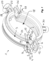
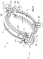
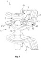
- a device 1 which has at least two components 2, 3, of which a first component 2 is designed as an upper part and a second component 3 as a lower part. These at least two components 2, 3 assigned to one another can be connected to one another using a closure 4.
- the two components 2, 3 assigned to one another and connectable to one another using the closure 4 can - as here - be designed as separate and/or separable components of the device 1 or can also be connected to one another in an articulated or flexible manner at a distance from the closure 4.
- the device 1 shown here is designed as a clamp and in particular as a pipe clamp, the clamp ring of which is formed by the ring halves serving as upper and lower components 2, 3.
- At least one tab 5, 6 protrudes at an angle in the area of a bend.
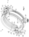
- one tab 5 has a through-opening 7 through which a locking pin 8 held by the associated other tab 6 with a pin head 9 provided at the free pin end can be pushed through in such a way that the locking pin 8 with its pin head 9 pivots a locking flap 10 from an initial position adjacent to the adjacent tab 5 against the restoring force of a spring element 11 into an open position until the locking flap 10 pivots back into its initial position in which the locking flap 10 penetrated by a pin shaft 12 of the locking pin 8 engages behind the pin head 9.
- the spring element 11 is designed here as a rubber ring 11. However, it is also possible for the spring element to be formed by several rubber rings, at least one leg spring and/or at least one spiral tension spring.
- closure flap 10 can be pivoted in the area of the bend about a pivot axis arranged in the longitudinal direction Pf1 of the bend line 13 of the bend and since the closure pin 8 held on the opposite other tab 6 is pushed with its pin head 9 through the through-opening 7, where the closure pin 8 pivots the closure flap 10 with its pin head 9 abutting the closure flap 10, the closure 4 can be closed in a simple manner with a comparatively low expenditure of force.
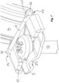
- At least the component 3 carrying the tab 5 with the closure flap 10 has at least one bead 14 in the area of the bend.
- This at least one bead 14 not only increases the load-bearing capacity of the component 3, but also secures the closure flap 10 in the longitudinal direction Pf1 of the bending line 13 of the bend against slipping, in particular during the pivoting movement of the closure flap 10.
- the closure flap 10 has at least one first recess or formation 15 on its transverse side facing the adjacent component 3, with which the closure flap 10 rests against the at least one bead 14 of the component 3.
- the spring element 11, which serves as a restoring force and is designed here as a rubber ring 11, is secured against rolling or slipping on at least one long side of the closure flap 10 by at least one second recess 16 or formation 17 of the closure flap 10.
- the device 1 shown here is also characterized by a comparatively high load-bearing capacity in the area of its closure 4, wherein the various components of the device 1 are designed and manufactured comparatively simply.
- the device 1 shown here is designed as a clamp and in particular as a pipe clamp.
- the clamp ring of the device 1 is formed from the ring halves, which are also referred to here as components 2, 3.
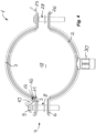
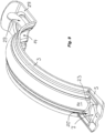
- the clamp ring formed from the components 2, 3 delimits a receiving space 18 which serves to receive an elongated object, in particular an elongated pipe section.
- An insertion opening is provided for inserting the elongated object into the receiving space 18 of the clamp ring, which can be closed using at least one closure 4.
- the device 1 is also characterized by a high load capacity in the area of its closure 4, Longer and correspondingly heavy pipe sections can also be inserted into the receiving space 18 delimited by the clamp ring, which are held securely in a pre-assembly position in the receiving space 18 after the locking pin 8 has been pushed through the through-opening 7 and after the locking flap 10 has been pivoted into the open position and the locking flap 10 has subsequently been pivoted back into the starting position adjacent to the adjacent tab 5, in which the pin head 9 of the locking pin 8 is gripped behind by the locking flap 10.
- At least one second protrusion 16 or indentation 17 is provided on opposite long sides of the closure flap 10 to securely hold the spring element 11, which is designed here as a rubber ring 11. Since at least one second protrusion 16 or indentation 17 is provided on opposite long sides of the closure flap 10, an unintentional rolling or slipping of the spring element 11 from the closure flap 10 is prevented.
- the spring element 11 which is designed here as a rubber ring 11, is secured on the closure flap 10 on both sides of the side facing the adjacent component 3 by means of a peg-shaped formation 16 protruding from the closure flap 10.
- the closure flap 10 additionally has on its opposite long sides a second recess 17 or notch which is open at the edge, in which recesses 17 the spring element 11 surrounds the closure flap 10.
- the spring element 11 which is designed here as a rubber ring 11, surrounds the closure flap 10 on both long sides of the closure flap 10 in a recess 17 or notch which is open at the edge, and since the spring element 11 is additionally secured on the Since the side of these recesses 17 facing the adjacent component 3 is secured by means of peg-shaped projections 16 protruding on both sides of the closure flap 10, the spring element 11 is also held securely on the closure flap 10 during the pivoting movements thereof.
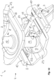
- a shaft opening 19 is provided which is open at the edge and is preferably in the shape of a circular segment. This opening is designed here as a recess or notch and whose contour is adapted to the cross-section of the pin shaft. Since the pin shaft 9 can penetrate the closure flap 10 in the area of the shaft opening 19 in the starting position of the closure flap 10, the closure flap 10 can pivot back into its starting position resting on the adjacent tab 5 and at the same time engage behind a comparatively large rear part of the pin head 9.
- the locking pin 8 is designed here as a threaded screw, the screw head of which forms the pin head 9 and the threaded shaft of which forms the pin shaft 12.
- the threaded screw serving as the locking pin 8 can be screwed with its external thread on the pin shaft 12 into an internal thread on the tab 6 facing away from the screw head.
- the tab 5 carrying the closure flap 10 has a recess 20 in the edge region of the through-opening 7 facing the adjacent component 3, wherein the closure flap 10 has a bend or bulge 21 which in the starting position rests against the recess 20 and is designed to be shaped to match it.
- the recess 20 extends from the transverse side of the tab 5 adjacent to the adjacent component 3 to approximately a center line of the through-opening 7 parallel to the bending line 13.
- the transverse side of the closure flap 10 facing away from the component 3 has a cut or drawn-in edge section 22 in the area of the recess 20, which in the initial position rests against the adjacent transverse side of the recess 20.
- the push-through opening 7 on the tab 5 and the shaft opening 19 on the closure flap 10, which is open at the edge as a notch or molding, are arranged concentrically to one another in the initial position.
- closure pin 8 with its pin head 9 is held half over the shaft diameter and half over the head diameter of the pin head 9, which prevents the parts forming the closure 4 from slipping relative to one another in any direction.
- Previously known closures which are also intended as clamp closures on the clamp ring of previously known clamps, usually have an open slot contour in at least one of the components of the closure, which then allows the locking pin 8 to slip in the longitudinal direction of the elongated hole.
- the contour positioning provided here does not require any further breakthrough through the tab 5, since the tab 5 and the closure flap 10 are aligned in position with each other by simply placing them on top of each other.
- the comparable closure flaps are hooked into the clamp ring via recesses or cutouts, which always results in a further weakening of the clamp ring.
- the surfaces on the tab 5 which delimit the recess 20 in the longitudinal direction form a positive connection with the surfaces on the closure flap 10 which delimit the bulge 21 in the longitudinal direction, whereby the tab 5 and the closure flap 10 are positioned relative to one another.
- the parts thus positioned relative to one another, namely the tab 5 and the closure flap 10 held on it now have two circular segments which are aligned concentrically to one another and which delimit the push-through opening 7 and the shaft opening 19 respectively.
- the tab 5 carrying the closure cap 10 is on the adjacent component 3 Since the edge region of the through-opening 7 facing away from the component 3 has a bead 23 or a bend which secures the pin head 9 against displacement in the direction facing away from the component 3, the concentricity of the through-opening 7 and the shaft opening 19 ensures that the locking pin 8, which is designed here as a threaded screw, is enclosed over the two diameters and thus the pin head is precisely fixed in position on the closure 4.
- clamp inserts 24, 25 on the inside, in particular made of an insulating plastic material. These clamp inserts 24, 25 enclose the adjacent component 2, 3 with the approximately U-shaped bent longitudinal edges of these clamp inserts 24, 25.
- the device 1 shown here and designed as a pipe clamp has a clamp ring that is made up of two separate ring halves.
- Each of these ring halves of the clamp ring also referred to here as components 2, 3, has a tab 5, 6; 26, 27 at the free ends of the ring halves, which is integrally formed on the adjacent ring half and protrudes outwards from it in an approximately radial direction in the area of a bend.
- These tabs 5, 6; 26, 27 are assigned to one another in pairs.
- the closure 4 is provided on the tabs 5, 6, the tabs 26, 27 are connected to one another via a clamping or fastening screw 28.
- the tab 26 has a threaded hole with an internal thread, into which the fastening screw 28 is screwed.
- a screw opening 29 is provided on the tab 27, through which the threaded shaft of the fastening screw 28 passes.
- the screw opening 29 is designed here as an elongated hole, the longitudinal direction of which extends in the longitudinal direction of the tab 27.
- the tab 27 is at its free tab end area angled so that the ring halves designed as components 2, 3 can be opened wide on the side of the clamp ring opposite the closure 4 at the insertion opening provided there to accommodate an elongated object.
- the tabs 26, 27 and the fastening screw 28 connecting them to one another serve as a joint of the device 1 designed as a pipe clamp.
- a threaded pin 30 is provided on the clamp ring and preferably on one of its two ring halves, in particular at an approximately equal distance from the tabs 5, 6; 26, 27, to which a threaded rod, a screw or similar connecting element can be mounted.
- the device 1 designed here as a clamp can be connected to the wall, ceiling or floor with a device carrier (not shown here).
Landscapes
- Engineering & Computer Science (AREA)
- General Engineering & Computer Science (AREA)
- Mechanical Engineering (AREA)
- Clamps And Clips (AREA)
- Package Frames And Binding Bands (AREA)
- Supports For Pipes And Cables (AREA)
Claims (15)
- Dispositif (1) comprenant deux éléments (2, 3), dont un premier élément (2) est réalisé en tant que partie supérieure et un deuxième élément (3) en tant que partie inférieure, sur chacun desquels éléments (2, 3) au moins une patte (5, 6) fait saillie de manière coudée dans la zone d'une courbure, lesquelles pattes (5, 6) sont associées par paires et forment au moins une fermeture (4) du dispositif (1), et dont une patte (5) présente une ouverture de passage (7) à travers laquelle un tenon de fermeture (8), maintenu par l'autre patte (6) associée et présentant une tête de tenon (9) prévue à l'extrémité libre du tenon, peut être inséré, de telle sorte que le tenon de fermeture (8) fait pivoter avec sa tête de tenon (9) un clapet de fermeture (10) d'une position initiale appliquée contre la patte (5) voisine dans une position ouverte à l'encontre de la force de rappel d'un élément élastique (11), jusqu'à ce que le clapet de fermeture (10) revienne dans sa position initiale dans laquelle le clapet de fermeture (10), traversé par une tige de tenon (12) du tenon de fermeture (8), s'engage derrière la tête de tenon (9), le clapet de fermeture (10) pouvant pivoter dans la zone de la courbure autour d'un axe de pivotement disposé dans la direction longitudinale (PF1) de la ligne de pliage (13) de la courbure, au moins l'élément (3) portant la patte (5) avec le clapet de fermeture (10) présentant au moins une nervure (14) dans la zone de la courbure, le clapet de fermeture (10) présentant, sur son côté transversal tourné vers l'élément (3) voisin, une première formation en creux ou en relief (15) et s'appliquant, par cette première formation en creux ou en relief (15), contre ladite au moins une nervure (14), et le clapet de fermeture (10) étant protégé contre un glissement dans la direction longitudinale (PF1) de la ligne de pliage (13),
caractérisé en ce que l'élément élastique (11), qui est réalisé sous la forme d'au moins un anneau en caoutchouc (11), d'au moins un ressort à branches et/ou d'au moins un ressort de traction hélicoïdal, est maintenu de manière sûre sur au moins un côté longitudinal du clapet de fermeture (10) par au moins une deuxième formation en creux ou en relief (16, 17) du clapet de fermeture (10) sur celui-ci. - Dispositif selon la revendication 1, caractérisé en ce que le dispositif (1) est réalisé sous la forme d'un collier et en particulier d'un collier de serrage qui possède une bague de collier qui présente un espace de réception (18) pour recevoir un objet allongé et une ouverture d'introduction pour introduire l'objet allongé dans l'espace de réception (18), laquelle peut être fermée à l'aide de ladite au moins une fermeture (4).
- Dispositif selon la revendication 1 ou 2, caractérisé en ce qu'il est prévu sur chacun des côtés longitudinaux opposés du clapet de fermeture (10) au moins une deuxième formation en relief (16) et/ou en creux (17) pour le maintien sûr de l'élément élastique (11).
- Dispositif selon l'une des revendications 1 à 3, caractérisé en ce que l'élément élastique (11) est maintenu de manière sûre sur le clapet de fermeture (10) des deux côtés, sur le côté tourné vers l'élément (3) voisin, au moyen d'une formation en relief (16) en forme de tenon faisant saillie sur le clapet de fermeture (10).
- Dispositif selon l'une des revendications 1 à 4, caractérisé en ce que, sur chacun des côtés opposés du clapet de fermeture (10), il est prévu sur celui-ci une deuxième formation en creux (17) ouverte sur le bord, dans lesquelles deuxièmes formations en creux (17) l'élément élastique (11) entoure le clapet de fermeture (10).
- Dispositif selon l'une des revendications 1 à 5, caractérisé en ce que des bords opposés du clapet de fermeture (10) sont coudés de telle sorte que le clapet de fermeture (10) reçoit entre lui, par ses bords longitudinaux coudés, la patte (5) voisine dans la position initiale.
- Dispositif selon l'une des revendications 1 à 6, caractérisé en ce que l'ouverture de passage (7) présente un diamètre d'ouverture agrandi par rapport au diamètre de la tête de tenon (9) et de préférence circulaire.
- Dispositif selon l'une des revendications 1 à 7, caractérisé en ce qu'il est prévu, sur le côté transversal du clapet de fermeture (10) tourné vers le tenon de fermeture (8), une ouverture de tige (19) ouverte sur le bord et de préférence en forme de segment de cercle, dont le contour est en particulier adapté à la forme de la section transversale de la tige de tenon (12).
- Dispositif selon l'une des revendications 1 à 8, caractérisé en ce que le tenon de fermeture (8) est réalisé sous la forme d'une vis filetée dont la tête de vis forme la tête de tenon (9) et dont la tige filetée forme la tige de tenon (12).
- Dispositif selon la revendication 9, caractérisé en ce que la vis filetée peut être vissée dans un filetage intérieur sur la patte (6) opposée à la tête de vis.
- Dispositif selon l'une des revendications 1 à 10, caractérisé en ce que la patte (5) portant le clapet de fermeture (10) présente un renfoncement (20) dans la zone de bordure de l'ouverture de passage (7) tournée vers l'élément (3) voisin, et en ce que le clapet de fermeture (10) possède un renflement ou un bombement (21) qui, dans la position initiale, s'applique contre le renfoncement (20) et est de préférence réalisé de manière adaptée à la forme de ce dernier.
- Dispositif selon la revendication 11, caractérisé en ce que le renfoncement (20) s'étend depuis le côté transversal de la patte (5) adjacent à l'élément (3) voisin jusqu'à environ une ligne médiane de l'ouverture de passage (7) parallèle à la ligne de pliage (13).
- Dispositif selon la revendication 11 ou 12, caractérisé en ce que le côté transversal du clapet de fermeture (10) opposé à l'élément (3) possède, dans la zone du renfoncement (20), une section de bord (22) entaillée ou renfoncée qui, dans la position initiale, s'applique contre le côté transversal voisin du renfoncement (20).
- Dispositif selon l'une des revendications 1 à 13, caractérisé en ce que l'ouverture de passage (7) sur la patte (5) et l'ouverture de tige (19) sur le clapet de fermeture (10) sont disposées concentriquement l'une par rapport à l'autre dans la position initiale.
- Dispositif selon l'une des revendications 1 à 14, caractérisé en ce que la patte (5) portant le clapet de fermeture (10) présente, sur la zone de bord de l'ouverture de passage (7) opposée à l'élément (3) voisin, une nervure (23) ou un renflement qui empêche la tête du tenon (9) de se déplacer dans la direction opposée à l'élément (3).
Applications Claiming Priority (1)
| Application Number | Priority Date | Filing Date | Title |
|---|---|---|---|
| DE102020134433.3A DE102020134433A1 (de) | 2020-12-21 | 2020-12-21 | Vorrichtung mit zwei Bauteilen, insbesondere Schelle mit einem Schellenring |
Publications (2)
| Publication Number | Publication Date |
|---|---|
| EP4019819A1 EP4019819A1 (fr) | 2022-06-29 |
| EP4019819B1 true EP4019819B1 (fr) | 2024-10-30 |
Family
ID=78957568
Family Applications (1)
| Application Number | Title | Priority Date | Filing Date |
|---|---|---|---|
| EP21215887.7A Active EP4019819B1 (fr) | 2020-12-21 | 2021-12-20 | Dispositif à deux composants, en particulier collier doté d'un anneau de collier |
Country Status (4)
| Country | Link |
|---|---|
| EP (1) | EP4019819B1 (fr) |
| DE (1) | DE102020134433A1 (fr) |
| ES (1) | ES3012390T3 (fr) |
| PL (1) | PL4019819T3 (fr) |
Families Citing this family (1)
| Publication number | Priority date | Publication date | Assignee | Title |
|---|---|---|---|---|
| CA3097280A1 (fr) * | 2020-10-23 | 2022-04-23 | Airbus Canada Limited Partnership | Collier |
Family Cites Families (5)
| Publication number | Priority date | Publication date | Assignee | Title |
|---|---|---|---|---|
| DE4026636A1 (de) * | 1990-08-23 | 1992-02-27 | Toge Duebel A Gerhard Gmbh | Rohrschelle |
| DE4124122A1 (de) | 1991-07-20 | 1993-01-21 | Wolfgang Halpaus | Vorrichtung zur verbindung zweier bauteile |
| DE4306870A1 (de) * | 1992-04-29 | 1993-11-04 | Toge Duebel A Gerhard Gmbh | Rohrschelle |
| NL1032991C2 (nl) * | 2006-12-05 | 2008-06-06 | Walraven Holding Bv J Van | Pijpbeugel. |
| EP3444513A1 (fr) | 2017-08-17 | 2019-02-20 | HILTI Aktiengesellschaft | Collier pourvu de patte de fermeture dans l'ouverture de passage pour bouchonde fermeture |
-
2020
- 2020-12-21 DE DE102020134433.3A patent/DE102020134433A1/de not_active Ceased
-
2021
- 2021-12-20 PL PL21215887.7T patent/PL4019819T3/pl unknown
- 2021-12-20 ES ES21215887T patent/ES3012390T3/es active Active
- 2021-12-20 EP EP21215887.7A patent/EP4019819B1/fr active Active
Also Published As
| Publication number | Publication date |
|---|---|
| ES3012390T3 (en) | 2025-04-09 |
| DE102020134433A1 (de) | 2022-06-23 |
| PL4019819T3 (pl) | 2025-03-17 |
| EP4019819A1 (fr) | 2022-06-29 |
Similar Documents
| Publication | Publication Date | Title |
|---|---|---|
| DE602004001734T2 (de) | Ein Befestigungselement zur Verbindung von an einem Trägerteil | |
| EP0205665B1 (fr) | Manchen d'ustensile de cuisine apte à être fixé sur un goujon | |
| EP0761130A2 (fr) | Ferrure de fixation pour panneaux frontaux de tiroir | |
| CH667139A5 (de) | Verbindungsbeschlag. | |
| EP1898105A2 (fr) | Fermeture rapide destinée à la liaison de deux composants | |
| EP3839275B1 (fr) | Pince de maintien d'une fermeture rapide, fermeture rapide ainsi que raccord de composant doté d'une telle fermeture rapide | |
| WO2000068582A1 (fr) | Element d'assemblage | |
| DE9311243U1 (de) | Drehverschluß | |
| DE3445935A1 (de) | Einteiliger schellenfoermiger halter fuer laengliche gegenstaende | |
| EP0471989B1 (fr) | Collier de serrage | |
| EP1439364A1 (fr) | Support pour échangeur de chaleur | |
| DE102007015129B3 (de) | Nicht demontierbarer Clip aus Kunststoff | |
| DE3436710C2 (de) | Rohrschelle | |
| DE10160729B4 (de) | Befestigungsanker mit Schraubenmutter | |
| EP0235629B1 (fr) | Dispositif de fixation pour conduites | |
| DD262893A5 (de) | Zweiteiliger verbindungsbeschlag | |
| EP0872677A2 (fr) | Collier de serrage | |
| EP0536471B1 (fr) | Plaque de moulage pour charnières de meubles | |
| EP4019819A1 (fr) | Dispositif à deux composants, en particulier collier doté d'un anneau de collier | |
| DE102019206750B4 (de) | Vorrichtung zum Ausgleichen von Toleranzen zwischen einem ersten Bauteil und einem zweiten Bauteil | |
| DE202006014151U1 (de) | Clip, Mutter und Clipmutter | |
| EP0454077B1 (fr) | Moyens de guidages pour les barres d'une espagnolette | |
| DE29822770U1 (de) | Scharnier | |
| DE2837373C2 (de) | Möbelbeschlagteil, insbesondere Montageplatte für einen Möbelscharnierarm | |
| DE2720096A1 (de) | Moebelscharnier |
Legal Events
| Date | Code | Title | Description |
|---|---|---|---|
| PUAI | Public reference made under article 153(3) epc to a published international application that has entered the european phase |
Free format text: ORIGINAL CODE: 0009012 |
|
| STAA | Information on the status of an ep patent application or granted ep patent |
Free format text: STATUS: THE APPLICATION HAS BEEN PUBLISHED |
|
| AK | Designated contracting states |
Kind code of ref document: A1 Designated state(s): AL AT BE BG CH CY CZ DE DK EE ES FI FR GB GR HR HU IE IS IT LI LT LU LV MC MK MT NL NO PL PT RO RS SE SI SK SM TR |
|
| STAA | Information on the status of an ep patent application or granted ep patent |
Free format text: STATUS: REQUEST FOR EXAMINATION WAS MADE |
|
| 17P | Request for examination filed |
Effective date: 20221019 |
|
| RBV | Designated contracting states (corrected) |
Designated state(s): AL AT BE BG CH CY CZ DE DK EE ES FI FR GB GR HR HU IE IS IT LI LT LU LV MC MK MT NL NO PL PT RO RS SE SI SK SM TR |
|
| RAV | Requested validation state of the european patent: fee paid |
Extension state: TN Effective date: 20230102 Extension state: MD Effective date: 20230102 Extension state: MA Effective date: 20230102 Extension state: KH Effective date: 20230102 |
|
| RAX | Requested extension states of the european patent have changed |
Extension state: ME Payment date: 20230102 Extension state: BA Payment date: 20230102 |
|
| STAA | Information on the status of an ep patent application or granted ep patent |
Free format text: STATUS: EXAMINATION IS IN PROGRESS |
|
| 17Q | First examination report despatched |
Effective date: 20230607 |
|
| GRAJ | Information related to disapproval of communication of intention to grant by the applicant or resumption of examination proceedings by the epo deleted |
Free format text: ORIGINAL CODE: EPIDOSDIGR1 |
|
| STAA | Information on the status of an ep patent application or granted ep patent |
Free format text: STATUS: GRANT OF PATENT IS INTENDED |
|
| GRAP | Despatch of communication of intention to grant a patent |
Free format text: ORIGINAL CODE: EPIDOSNIGR1 |
|
| GRAP | Despatch of communication of intention to grant a patent |
Free format text: ORIGINAL CODE: EPIDOSNIGR1 |
|
| INTG | Intention to grant announced |
Effective date: 20240614 |
|
| GRAS | Grant fee paid |
Free format text: ORIGINAL CODE: EPIDOSNIGR3 |
|
| GRAA | (expected) grant |
Free format text: ORIGINAL CODE: 0009210 |
|
| STAA | Information on the status of an ep patent application or granted ep patent |
Free format text: STATUS: THE PATENT HAS BEEN GRANTED |
|
| AK | Designated contracting states |
Kind code of ref document: B1 Designated state(s): AL AT BE BG CH CY CZ DE DK EE ES FI FR GB GR HR HU IE IS IT LI LT LU LV MC MK MT NL NO PL PT RO RS SE SI SK SM TR |
|
| REG | Reference to a national code |
Ref country code: GB Ref legal event code: FG4D Free format text: NOT ENGLISH |
|
| REG | Reference to a national code |
Ref country code: CH Ref legal event code: EP |
|
| REG | Reference to a national code |
Ref country code: DE Ref legal event code: R096 Ref document number: 502021005630 Country of ref document: DE |
|
| REG | Reference to a national code |
Ref country code: IE Ref legal event code: FG4D Free format text: LANGUAGE OF EP DOCUMENT: GERMAN |
|
| REG | Reference to a national code |
Ref country code: NL Ref legal event code: FP |
|
| REG | Reference to a national code |
Ref country code: LT Ref legal event code: MG9D |
|
| REG | Reference to a national code |
Ref country code: ES Ref legal event code: FG2A Ref document number: 3012390 Country of ref document: ES Kind code of ref document: T3 Effective date: 20250409 |
|
| PG25 | Lapsed in a contracting state [announced via postgrant information from national office to epo] |
Ref country code: PT Free format text: LAPSE BECAUSE OF FAILURE TO SUBMIT A TRANSLATION OF THE DESCRIPTION OR TO PAY THE FEE WITHIN THE PRESCRIBED TIME-LIMIT Effective date: 20250228 Ref country code: HR Free format text: LAPSE BECAUSE OF FAILURE TO SUBMIT A TRANSLATION OF THE DESCRIPTION OR TO PAY THE FEE WITHIN THE PRESCRIBED TIME-LIMIT Effective date: 20241030 Ref country code: IS Free format text: LAPSE BECAUSE OF FAILURE TO SUBMIT A TRANSLATION OF THE DESCRIPTION OR TO PAY THE FEE WITHIN THE PRESCRIBED TIME-LIMIT Effective date: 20250228 |
|
| PG25 | Lapsed in a contracting state [announced via postgrant information from national office to epo] |
Ref country code: FI Free format text: LAPSE BECAUSE OF FAILURE TO SUBMIT A TRANSLATION OF THE DESCRIPTION OR TO PAY THE FEE WITHIN THE PRESCRIBED TIME-LIMIT Effective date: 20241030 |
|
| PG25 | Lapsed in a contracting state [announced via postgrant information from national office to epo] |
Ref country code: BG Free format text: LAPSE BECAUSE OF FAILURE TO SUBMIT A TRANSLATION OF THE DESCRIPTION OR TO PAY THE FEE WITHIN THE PRESCRIBED TIME-LIMIT Effective date: 20241030 |
|
| PG25 | Lapsed in a contracting state [announced via postgrant information from national office to epo] |
Ref country code: NO Free format text: LAPSE BECAUSE OF FAILURE TO SUBMIT A TRANSLATION OF THE DESCRIPTION OR TO PAY THE FEE WITHIN THE PRESCRIBED TIME-LIMIT Effective date: 20250130 |
|
| PG25 | Lapsed in a contracting state [announced via postgrant information from national office to epo] |
Ref country code: LV Free format text: LAPSE BECAUSE OF FAILURE TO SUBMIT A TRANSLATION OF THE DESCRIPTION OR TO PAY THE FEE WITHIN THE PRESCRIBED TIME-LIMIT Effective date: 20241030 Ref country code: GR Free format text: LAPSE BECAUSE OF FAILURE TO SUBMIT A TRANSLATION OF THE DESCRIPTION OR TO PAY THE FEE WITHIN THE PRESCRIBED TIME-LIMIT Effective date: 20250131 |
|
| PG25 | Lapsed in a contracting state [announced via postgrant information from national office to epo] |
Ref country code: RS Free format text: LAPSE BECAUSE OF FAILURE TO SUBMIT A TRANSLATION OF THE DESCRIPTION OR TO PAY THE FEE WITHIN THE PRESCRIBED TIME-LIMIT Effective date: 20250130 |
|
| PG25 | Lapsed in a contracting state [announced via postgrant information from national office to epo] |
Ref country code: SM Free format text: LAPSE BECAUSE OF FAILURE TO SUBMIT A TRANSLATION OF THE DESCRIPTION OR TO PAY THE FEE WITHIN THE PRESCRIBED TIME-LIMIT Effective date: 20241030 |
|
| PG25 | Lapsed in a contracting state [announced via postgrant information from national office to epo] |
Ref country code: MC Free format text: LAPSE BECAUSE OF FAILURE TO SUBMIT A TRANSLATION OF THE DESCRIPTION OR TO PAY THE FEE WITHIN THE PRESCRIBED TIME-LIMIT Effective date: 20241030 |
|
| PG25 | Lapsed in a contracting state [announced via postgrant information from national office to epo] |
Ref country code: DK Free format text: LAPSE BECAUSE OF FAILURE TO SUBMIT A TRANSLATION OF THE DESCRIPTION OR TO PAY THE FEE WITHIN THE PRESCRIBED TIME-LIMIT Effective date: 20241030 |
|
| VS25 | Lapsed in a validation state [announced via postgrant information from nat. office to epo] |
Ref country code: MD Free format text: LAPSE BECAUSE OF FAILURE TO SUBMIT A TRANSLATION OF THE DESCRIPTION OR TO PAY THE FEE WITHIN THE PRESCRIBED TIME-LIMIT Effective date: 20241030 |
|
| PG25 | Lapsed in a contracting state [announced via postgrant information from national office to epo] |
Ref country code: EE Free format text: LAPSE BECAUSE OF FAILURE TO SUBMIT A TRANSLATION OF THE DESCRIPTION OR TO PAY THE FEE WITHIN THE PRESCRIBED TIME-LIMIT Effective date: 20241030 |
|
| PG25 | Lapsed in a contracting state [announced via postgrant information from national office to epo] |
Ref country code: RO Free format text: LAPSE BECAUSE OF FAILURE TO SUBMIT A TRANSLATION OF THE DESCRIPTION OR TO PAY THE FEE WITHIN THE PRESCRIBED TIME-LIMIT Effective date: 20241030 |
|
| PG25 | Lapsed in a contracting state [announced via postgrant information from national office to epo] |
Ref country code: SK Free format text: LAPSE BECAUSE OF FAILURE TO SUBMIT A TRANSLATION OF THE DESCRIPTION OR TO PAY THE FEE WITHIN THE PRESCRIBED TIME-LIMIT Effective date: 20241030 |
|
| PG25 | Lapsed in a contracting state [announced via postgrant information from national office to epo] |
Ref country code: CZ Free format text: LAPSE BECAUSE OF FAILURE TO SUBMIT A TRANSLATION OF THE DESCRIPTION OR TO PAY THE FEE WITHIN THE PRESCRIBED TIME-LIMIT Effective date: 20241030 |
|
| PG25 | Lapsed in a contracting state [announced via postgrant information from national office to epo] |
Ref country code: IT Free format text: LAPSE BECAUSE OF FAILURE TO SUBMIT A TRANSLATION OF THE DESCRIPTION OR TO PAY THE FEE WITHIN THE PRESCRIBED TIME-LIMIT Effective date: 20241030 |
|
| REG | Reference to a national code |
Ref country code: DE Ref legal event code: R097 Ref document number: 502021005630 Country of ref document: DE |
|
| PG25 | Lapsed in a contracting state [announced via postgrant information from national office to epo] |
Ref country code: LU Free format text: LAPSE BECAUSE OF NON-PAYMENT OF DUE FEES Effective date: 20241220 |
|
| PLBE | No opposition filed within time limit |
Free format text: ORIGINAL CODE: 0009261 |
|
| STAA | Information on the status of an ep patent application or granted ep patent |
Free format text: STATUS: NO OPPOSITION FILED WITHIN TIME LIMIT |
|
| PG25 | Lapsed in a contracting state [announced via postgrant information from national office to epo] |
Ref country code: SE Free format text: LAPSE BECAUSE OF FAILURE TO SUBMIT A TRANSLATION OF THE DESCRIPTION OR TO PAY THE FEE WITHIN THE PRESCRIBED TIME-LIMIT Effective date: 20241030 |
|
| 26N | No opposition filed |
Effective date: 20250731 |
|
| REG | Reference to a national code |
Ref country code: BE Ref legal event code: MM Effective date: 20241231 |
|
| PG25 | Lapsed in a contracting state [announced via postgrant information from national office to epo] |
Ref country code: BE Free format text: LAPSE BECAUSE OF NON-PAYMENT OF DUE FEES Effective date: 20241231 |
|
| PG25 | Lapsed in a contracting state [announced via postgrant information from national office to epo] |
Ref country code: FR Free format text: LAPSE BECAUSE OF NON-PAYMENT OF DUE FEES Effective date: 20241230 |
|
| PG25 | Lapsed in a contracting state [announced via postgrant information from national office to epo] |
Ref country code: IE Free format text: LAPSE BECAUSE OF NON-PAYMENT OF DUE FEES Effective date: 20241220 |
|
| REG | Reference to a national code |
Ref country code: CH Ref legal event code: U11 Free format text: ST27 STATUS EVENT CODE: U-0-0-U10-U11 (AS PROVIDED BY THE NATIONAL OFFICE) Effective date: 20260101 |
|
| PGFP | Annual fee paid to national office [announced via postgrant information from national office to epo] |
Ref country code: GB Payment date: 20251218 Year of fee payment: 5 |
|
| PGFP | Annual fee paid to national office [announced via postgrant information from national office to epo] |
Ref country code: AT Payment date: 20260113 Year of fee payment: 5 |
|
| PGFP | Annual fee paid to national office [announced via postgrant information from national office to epo] |
Ref country code: NL Payment date: 20251217 Year of fee payment: 5 |
|
| PGFP | Annual fee paid to national office [announced via postgrant information from national office to epo] |
Ref country code: TR Payment date: 20251216 Year of fee payment: 5 |
|
| PGFP | Annual fee paid to national office [announced via postgrant information from national office to epo] |
Ref country code: PL Payment date: 20251208 Year of fee payment: 5 |
|
| VS25 | Lapsed in a validation state [announced via postgrant information from nat. office to epo] |
Ref country code: MA Free format text: FAILURE TO ELECT DOMICILE IN THE NATIONAL COUNTRY Effective date: 20250131 |
|
| VS25 | Lapsed in a validation state [announced via postgrant information from nat. office to epo] |
Ref country code: MA Free format text: LAPSE BECAUSE OF FAILURE TO SUBMIT A TRANSLATION OF THE DESCRIPTION OR TO PAY THE FEE WITHIN THE PRESCRIBED TIME-LIMIT Effective date: 20241030 |
|
| PGFP | Annual fee paid to national office [announced via postgrant information from national office to epo] |
Ref country code: ES Payment date: 20260119 Year of fee payment: 5 |
|
| PGFP | Annual fee paid to national office [announced via postgrant information from national office to epo] |
Ref country code: DE Payment date: 20251223 Year of fee payment: 5 |
|
| PGFP | Annual fee paid to national office [announced via postgrant information from national office to epo] |
Ref country code: CH Payment date: 20260101 Year of fee payment: 5 |