EP4019824A1 - System und verfahren zur vorkühlung einer benzinzapfsäule - Google Patents
System und verfahren zur vorkühlung einer benzinzapfsäule Download PDFInfo
- Publication number
- EP4019824A1 EP4019824A1 EP21154230.3A EP21154230A EP4019824A1 EP 4019824 A1 EP4019824 A1 EP 4019824A1 EP 21154230 A EP21154230 A EP 21154230A EP 4019824 A1 EP4019824 A1 EP 4019824A1
- Authority
- EP
- European Patent Office
- Prior art keywords
- dispenser
- vapor
- storage tank
- fuel
- liquefied fuel
- Prior art date
- Legal status (The legal status is an assumption and is not a legal conclusion. Google has not performed a legal analysis and makes no representation as to the accuracy of the status listed.)
- Granted
Links
Images


Classifications
-
- B—PERFORMING OPERATIONS; TRANSPORTING
- B67—OPENING, CLOSING OR CLEANING BOTTLES, JARS OR SIMILAR CONTAINERS; LIQUID HANDLING
- B67D—DISPENSING, DELIVERING OR TRANSFERRING LIQUIDS, NOT OTHERWISE PROVIDED FOR
- B67D7/00—Apparatus or devices for transferring liquids from bulk storage containers or reservoirs into vehicles or into portable containers, e.g. for retail sale purposes
- B67D7/06—Details or accessories
- B67D7/80—Arrangements of heating or cooling devices for liquids to be transferred
-
- B—PERFORMING OPERATIONS; TRANSPORTING
- B67—OPENING, CLOSING OR CLEANING BOTTLES, JARS OR SIMILAR CONTAINERS; LIQUID HANDLING
- B67D—DISPENSING, DELIVERING OR TRANSFERRING LIQUIDS, NOT OTHERWISE PROVIDED FOR
- B67D7/00—Apparatus or devices for transferring liquids from bulk storage containers or reservoirs into vehicles or into portable containers, e.g. for retail sale purposes
- B67D7/06—Details or accessories
- B67D7/36—Arrangements of flow- or pressure-control valves
-
- F—MECHANICAL ENGINEERING; LIGHTING; HEATING; WEAPONS; BLASTING
- F17—STORING OR DISTRIBUTING GASES OR LIQUIDS
- F17C—VESSELS FOR CONTAINING OR STORING COMPRESSED, LIQUEFIED OR SOLIDIFIED GASES; FIXED-CAPACITY GAS-HOLDERS; FILLING VESSELS WITH, OR DISCHARGING FROM VESSELS, COMPRESSED, LIQUEFIED, OR SOLIDIFIED GASES
- F17C13/00—Details of vessels or of the filling or discharging of vessels
- F17C13/002—Details of vessels or of the filling or discharging of vessels for vessels under pressure
-
- F—MECHANICAL ENGINEERING; LIGHTING; HEATING; WEAPONS; BLASTING
- F17—STORING OR DISTRIBUTING GASES OR LIQUIDS
- F17C—VESSELS FOR CONTAINING OR STORING COMPRESSED, LIQUEFIED OR SOLIDIFIED GASES; FIXED-CAPACITY GAS-HOLDERS; FILLING VESSELS WITH, OR DISCHARGING FROM VESSELS, COMPRESSED, LIQUEFIED, OR SOLIDIFIED GASES
- F17C13/00—Details of vessels or of the filling or discharging of vessels
- F17C13/02—Special adaptations of indicating, measuring, or monitoring equipment
- F17C13/025—Special adaptations of indicating, measuring, or monitoring equipment having the pressure as the parameter
-
- F—MECHANICAL ENGINEERING; LIGHTING; HEATING; WEAPONS; BLASTING
- F17—STORING OR DISTRIBUTING GASES OR LIQUIDS
- F17C—VESSELS FOR CONTAINING OR STORING COMPRESSED, LIQUEFIED OR SOLIDIFIED GASES; FIXED-CAPACITY GAS-HOLDERS; FILLING VESSELS WITH, OR DISCHARGING FROM VESSELS, COMPRESSED, LIQUEFIED, OR SOLIDIFIED GASES
- F17C13/00—Details of vessels or of the filling or discharging of vessels
- F17C13/02—Special adaptations of indicating, measuring, or monitoring equipment
- F17C13/026—Special adaptations of indicating, measuring, or monitoring equipment having the temperature as the parameter
-
- F—MECHANICAL ENGINEERING; LIGHTING; HEATING; WEAPONS; BLASTING
- F17—STORING OR DISTRIBUTING GASES OR LIQUIDS
- F17C—VESSELS FOR CONTAINING OR STORING COMPRESSED, LIQUEFIED OR SOLIDIFIED GASES; FIXED-CAPACITY GAS-HOLDERS; FILLING VESSELS WITH, OR DISCHARGING FROM VESSELS, COMPRESSED, LIQUEFIED, OR SOLIDIFIED GASES
- F17C13/00—Details of vessels or of the filling or discharging of vessels
- F17C13/04—Arrangement or mounting of valves
-
- F—MECHANICAL ENGINEERING; LIGHTING; HEATING; WEAPONS; BLASTING
- F17—STORING OR DISTRIBUTING GASES OR LIQUIDS
- F17C—VESSELS FOR CONTAINING OR STORING COMPRESSED, LIQUEFIED OR SOLIDIFIED GASES; FIXED-CAPACITY GAS-HOLDERS; FILLING VESSELS WITH, OR DISCHARGING FROM VESSELS, COMPRESSED, LIQUEFIED, OR SOLIDIFIED GASES
- F17C5/00—Methods or apparatus for filling containers with liquefied, solidified, or compressed gases under pressures
- F17C5/002—Automated filling apparatus
- F17C5/007—Automated filling apparatus for individual gas tanks or containers, e.g. in vehicles
-
- F—MECHANICAL ENGINEERING; LIGHTING; HEATING; WEAPONS; BLASTING
- F17—STORING OR DISTRIBUTING GASES OR LIQUIDS
- F17C—VESSELS FOR CONTAINING OR STORING COMPRESSED, LIQUEFIED OR SOLIDIFIED GASES; FIXED-CAPACITY GAS-HOLDERS; FILLING VESSELS WITH, OR DISCHARGING FROM VESSELS, COMPRESSED, LIQUEFIED, OR SOLIDIFIED GASES
- F17C5/00—Methods or apparatus for filling containers with liquefied, solidified, or compressed gases under pressures
- F17C5/06—Methods or apparatus for filling containers with liquefied, solidified, or compressed gases under pressures for filling with compressed gases
-
- F—MECHANICAL ENGINEERING; LIGHTING; HEATING; WEAPONS; BLASTING
- F17—STORING OR DISTRIBUTING GASES OR LIQUIDS
- F17C—VESSELS FOR CONTAINING OR STORING COMPRESSED, LIQUEFIED OR SOLIDIFIED GASES; FIXED-CAPACITY GAS-HOLDERS; FILLING VESSELS WITH, OR DISCHARGING FROM VESSELS, COMPRESSED, LIQUEFIED, OR SOLIDIFIED GASES
- F17C7/00—Methods or apparatus for discharging liquefied, solidified, or compressed gases from pressure vessels, not covered by another subclass
-
- F—MECHANICAL ENGINEERING; LIGHTING; HEATING; WEAPONS; BLASTING
- F17—STORING OR DISTRIBUTING GASES OR LIQUIDS
- F17C—VESSELS FOR CONTAINING OR STORING COMPRESSED, LIQUEFIED OR SOLIDIFIED GASES; FIXED-CAPACITY GAS-HOLDERS; FILLING VESSELS WITH, OR DISCHARGING FROM VESSELS, COMPRESSED, LIQUEFIED, OR SOLIDIFIED GASES
- F17C7/00—Methods or apparatus for discharging liquefied, solidified, or compressed gases from pressure vessels, not covered by another subclass
- F17C7/02—Discharging liquefied gases
- F17C7/04—Discharging liquefied gases with change of state, e.g. vaporisation
-
- F—MECHANICAL ENGINEERING; LIGHTING; HEATING; WEAPONS; BLASTING
- F17—STORING OR DISTRIBUTING GASES OR LIQUIDS
- F17D—PIPE-LINE SYSTEMS; PIPE-LINES
- F17D1/00—Pipe-line systems
- F17D1/02—Pipe-line systems for gases or vapours
-
- F—MECHANICAL ENGINEERING; LIGHTING; HEATING; WEAPONS; BLASTING
- F17—STORING OR DISTRIBUTING GASES OR LIQUIDS
- F17D—PIPE-LINE SYSTEMS; PIPE-LINES
- F17D1/00—Pipe-line systems
- F17D1/08—Pipe-line systems for liquids or viscous products
- F17D1/14—Conveying liquids or viscous products by pumping
-
- F—MECHANICAL ENGINEERING; LIGHTING; HEATING; WEAPONS; BLASTING
- F17—STORING OR DISTRIBUTING GASES OR LIQUIDS
- F17D—PIPE-LINE SYSTEMS; PIPE-LINES
- F17D3/00—Arrangements for supervising or controlling working operations
-
- F—MECHANICAL ENGINEERING; LIGHTING; HEATING; WEAPONS; BLASTING
- F17—STORING OR DISTRIBUTING GASES OR LIQUIDS
- F17D—PIPE-LINE SYSTEMS; PIPE-LINES
- F17D3/00—Arrangements for supervising or controlling working operations
- F17D3/01—Arrangements for supervising or controlling working operations for controlling, signalling, or supervising the conveyance of a product
-
- F—MECHANICAL ENGINEERING; LIGHTING; HEATING; WEAPONS; BLASTING
- F17—STORING OR DISTRIBUTING GASES OR LIQUIDS
- F17C—VESSELS FOR CONTAINING OR STORING COMPRESSED, LIQUEFIED OR SOLIDIFIED GASES; FIXED-CAPACITY GAS-HOLDERS; FILLING VESSELS WITH, OR DISCHARGING FROM VESSELS, COMPRESSED, LIQUEFIED, OR SOLIDIFIED GASES
- F17C2205/00—Vessel construction, in particular mounting arrangements, attachments or identifications means
- F17C2205/03—Fluid connections, filters, valves, closure means or other attachments
- F17C2205/0302—Fittings, valves, filters, or components in connection with the gas storage device
- F17C2205/0323—Valves
-
- F—MECHANICAL ENGINEERING; LIGHTING; HEATING; WEAPONS; BLASTING
- F17—STORING OR DISTRIBUTING GASES OR LIQUIDS
- F17C—VESSELS FOR CONTAINING OR STORING COMPRESSED, LIQUEFIED OR SOLIDIFIED GASES; FIXED-CAPACITY GAS-HOLDERS; FILLING VESSELS WITH, OR DISCHARGING FROM VESSELS, COMPRESSED, LIQUEFIED, OR SOLIDIFIED GASES
- F17C2205/00—Vessel construction, in particular mounting arrangements, attachments or identifications means
- F17C2205/03—Fluid connections, filters, valves, closure means or other attachments
- F17C2205/0302—Fittings, valves, filters, or components in connection with the gas storage device
- F17C2205/0323—Valves
- F17C2205/0332—Safety valves or pressure relief valves
-
- F—MECHANICAL ENGINEERING; LIGHTING; HEATING; WEAPONS; BLASTING
- F17—STORING OR DISTRIBUTING GASES OR LIQUIDS
- F17C—VESSELS FOR CONTAINING OR STORING COMPRESSED, LIQUEFIED OR SOLIDIFIED GASES; FIXED-CAPACITY GAS-HOLDERS; FILLING VESSELS WITH, OR DISCHARGING FROM VESSELS, COMPRESSED, LIQUEFIED, OR SOLIDIFIED GASES
- F17C2205/00—Vessel construction, in particular mounting arrangements, attachments or identifications means
- F17C2205/03—Fluid connections, filters, valves, closure means or other attachments
- F17C2205/0302—Fittings, valves, filters, or components in connection with the gas storage device
- F17C2205/0376—Dispensing pistols
-
- F—MECHANICAL ENGINEERING; LIGHTING; HEATING; WEAPONS; BLASTING
- F17—STORING OR DISTRIBUTING GASES OR LIQUIDS
- F17C—VESSELS FOR CONTAINING OR STORING COMPRESSED, LIQUEFIED OR SOLIDIFIED GASES; FIXED-CAPACITY GAS-HOLDERS; FILLING VESSELS WITH, OR DISCHARGING FROM VESSELS, COMPRESSED, LIQUEFIED, OR SOLIDIFIED GASES
- F17C2221/00—Handled fluid, in particular type of fluid
- F17C2221/01—Pure fluids
- F17C2221/012—Hydrogen
-
- F—MECHANICAL ENGINEERING; LIGHTING; HEATING; WEAPONS; BLASTING
- F17—STORING OR DISTRIBUTING GASES OR LIQUIDS
- F17C—VESSELS FOR CONTAINING OR STORING COMPRESSED, LIQUEFIED OR SOLIDIFIED GASES; FIXED-CAPACITY GAS-HOLDERS; FILLING VESSELS WITH, OR DISCHARGING FROM VESSELS, COMPRESSED, LIQUEFIED, OR SOLIDIFIED GASES
- F17C2223/00—Handled fluid before transfer, i.e. state of fluid when stored in the vessel or before transfer from the vessel
- F17C2223/01—Handled fluid before transfer, i.e. state of fluid when stored in the vessel or before transfer from the vessel characterised by the phase
- F17C2223/0146—Two-phase
- F17C2223/0153—Liquefied gas, e.g. LPG, GPL
-
- F—MECHANICAL ENGINEERING; LIGHTING; HEATING; WEAPONS; BLASTING
- F17—STORING OR DISTRIBUTING GASES OR LIQUIDS
- F17C—VESSELS FOR CONTAINING OR STORING COMPRESSED, LIQUEFIED OR SOLIDIFIED GASES; FIXED-CAPACITY GAS-HOLDERS; FILLING VESSELS WITH, OR DISCHARGING FROM VESSELS, COMPRESSED, LIQUEFIED, OR SOLIDIFIED GASES
- F17C2223/00—Handled fluid before transfer, i.e. state of fluid when stored in the vessel or before transfer from the vessel
- F17C2223/01—Handled fluid before transfer, i.e. state of fluid when stored in the vessel or before transfer from the vessel characterised by the phase
- F17C2223/0146—Two-phase
- F17C2223/0153—Liquefied gas, e.g. LPG, GPL
- F17C2223/0161—Liquefied gas, e.g. LPG, GPL cryogenic, e.g. LNG, GNL, PLNG
-
- F—MECHANICAL ENGINEERING; LIGHTING; HEATING; WEAPONS; BLASTING
- F17—STORING OR DISTRIBUTING GASES OR LIQUIDS
- F17C—VESSELS FOR CONTAINING OR STORING COMPRESSED, LIQUEFIED OR SOLIDIFIED GASES; FIXED-CAPACITY GAS-HOLDERS; FILLING VESSELS WITH, OR DISCHARGING FROM VESSELS, COMPRESSED, LIQUEFIED, OR SOLIDIFIED GASES
- F17C2223/00—Handled fluid before transfer, i.e. state of fluid when stored in the vessel or before transfer from the vessel
- F17C2223/03—Handled fluid before transfer, i.e. state of fluid when stored in the vessel or before transfer from the vessel characterised by the pressure level
- F17C2223/033—Small pressure, e.g. for liquefied gas
-
- F—MECHANICAL ENGINEERING; LIGHTING; HEATING; WEAPONS; BLASTING
- F17—STORING OR DISTRIBUTING GASES OR LIQUIDS
- F17C—VESSELS FOR CONTAINING OR STORING COMPRESSED, LIQUEFIED OR SOLIDIFIED GASES; FIXED-CAPACITY GAS-HOLDERS; FILLING VESSELS WITH, OR DISCHARGING FROM VESSELS, COMPRESSED, LIQUEFIED, OR SOLIDIFIED GASES
- F17C2225/00—Handled fluid after transfer, i.e. state of fluid after transfer from the vessel
- F17C2225/01—Handled fluid after transfer, i.e. state of fluid after transfer from the vessel characterised by the phase
- F17C2225/0107—Single phase
- F17C2225/0115—Single phase dense or supercritical, i.e. at high pressure and high density
-
- F—MECHANICAL ENGINEERING; LIGHTING; HEATING; WEAPONS; BLASTING
- F17—STORING OR DISTRIBUTING GASES OR LIQUIDS
- F17C—VESSELS FOR CONTAINING OR STORING COMPRESSED, LIQUEFIED OR SOLIDIFIED GASES; FIXED-CAPACITY GAS-HOLDERS; FILLING VESSELS WITH, OR DISCHARGING FROM VESSELS, COMPRESSED, LIQUEFIED, OR SOLIDIFIED GASES
- F17C2225/00—Handled fluid after transfer, i.e. state of fluid after transfer from the vessel
- F17C2225/01—Handled fluid after transfer, i.e. state of fluid after transfer from the vessel characterised by the phase
- F17C2225/0107—Single phase
- F17C2225/0123—Single phase gaseous, e.g. CNG, GNC
-
- F—MECHANICAL ENGINEERING; LIGHTING; HEATING; WEAPONS; BLASTING
- F17—STORING OR DISTRIBUTING GASES OR LIQUIDS
- F17C—VESSELS FOR CONTAINING OR STORING COMPRESSED, LIQUEFIED OR SOLIDIFIED GASES; FIXED-CAPACITY GAS-HOLDERS; FILLING VESSELS WITH, OR DISCHARGING FROM VESSELS, COMPRESSED, LIQUEFIED, OR SOLIDIFIED GASES
- F17C2225/00—Handled fluid after transfer, i.e. state of fluid after transfer from the vessel
- F17C2225/03—Handled fluid after transfer, i.e. state of fluid after transfer from the vessel characterised by the pressure level
- F17C2225/036—Very high pressure, i.e. above 80 bars
-
- F—MECHANICAL ENGINEERING; LIGHTING; HEATING; WEAPONS; BLASTING
- F17—STORING OR DISTRIBUTING GASES OR LIQUIDS
- F17C—VESSELS FOR CONTAINING OR STORING COMPRESSED, LIQUEFIED OR SOLIDIFIED GASES; FIXED-CAPACITY GAS-HOLDERS; FILLING VESSELS WITH, OR DISCHARGING FROM VESSELS, COMPRESSED, LIQUEFIED, OR SOLIDIFIED GASES
- F17C2227/00—Transfer of fluids, i.e. method or means for transferring the fluid; Heat exchange with the fluid
- F17C2227/01—Propulsion of the fluid
- F17C2227/0128—Propulsion of the fluid with pumps or compressors
- F17C2227/0135—Pumps
-
- F—MECHANICAL ENGINEERING; LIGHTING; HEATING; WEAPONS; BLASTING
- F17—STORING OR DISTRIBUTING GASES OR LIQUIDS
- F17C—VESSELS FOR CONTAINING OR STORING COMPRESSED, LIQUEFIED OR SOLIDIFIED GASES; FIXED-CAPACITY GAS-HOLDERS; FILLING VESSELS WITH, OR DISCHARGING FROM VESSELS, COMPRESSED, LIQUEFIED, OR SOLIDIFIED GASES
- F17C2227/00—Transfer of fluids, i.e. method or means for transferring the fluid; Heat exchange with the fluid
- F17C2227/03—Heat exchange with the fluid
- F17C2227/0302—Heat exchange with the fluid by heating
- F17C2227/0306—Heat exchange with the fluid by heating using the same fluid
-
- F—MECHANICAL ENGINEERING; LIGHTING; HEATING; WEAPONS; BLASTING
- F17—STORING OR DISTRIBUTING GASES OR LIQUIDS
- F17C—VESSELS FOR CONTAINING OR STORING COMPRESSED, LIQUEFIED OR SOLIDIFIED GASES; FIXED-CAPACITY GAS-HOLDERS; FILLING VESSELS WITH, OR DISCHARGING FROM VESSELS, COMPRESSED, LIQUEFIED, OR SOLIDIFIED GASES
- F17C2227/00—Transfer of fluids, i.e. method or means for transferring the fluid; Heat exchange with the fluid
- F17C2227/03—Heat exchange with the fluid
- F17C2227/0302—Heat exchange with the fluid by heating
- F17C2227/0309—Heat exchange with the fluid by heating using another fluid
-
- F—MECHANICAL ENGINEERING; LIGHTING; HEATING; WEAPONS; BLASTING
- F17—STORING OR DISTRIBUTING GASES OR LIQUIDS
- F17C—VESSELS FOR CONTAINING OR STORING COMPRESSED, LIQUEFIED OR SOLIDIFIED GASES; FIXED-CAPACITY GAS-HOLDERS; FILLING VESSELS WITH, OR DISCHARGING FROM VESSELS, COMPRESSED, LIQUEFIED, OR SOLIDIFIED GASES
- F17C2227/00—Transfer of fluids, i.e. method or means for transferring the fluid; Heat exchange with the fluid
- F17C2227/03—Heat exchange with the fluid
- F17C2227/0337—Heat exchange with the fluid by cooling
- F17C2227/0339—Heat exchange with the fluid by cooling using the same fluid
-
- F—MECHANICAL ENGINEERING; LIGHTING; HEATING; WEAPONS; BLASTING
- F17—STORING OR DISTRIBUTING GASES OR LIQUIDS
- F17C—VESSELS FOR CONTAINING OR STORING COMPRESSED, LIQUEFIED OR SOLIDIFIED GASES; FIXED-CAPACITY GAS-HOLDERS; FILLING VESSELS WITH, OR DISCHARGING FROM VESSELS, COMPRESSED, LIQUEFIED, OR SOLIDIFIED GASES
- F17C2227/00—Transfer of fluids, i.e. method or means for transferring the fluid; Heat exchange with the fluid
- F17C2227/03—Heat exchange with the fluid
- F17C2227/0367—Localisation of heat exchange
- F17C2227/0388—Localisation of heat exchange separate
-
- F—MECHANICAL ENGINEERING; LIGHTING; HEATING; WEAPONS; BLASTING
- F17—STORING OR DISTRIBUTING GASES OR LIQUIDS
- F17C—VESSELS FOR CONTAINING OR STORING COMPRESSED, LIQUEFIED OR SOLIDIFIED GASES; FIXED-CAPACITY GAS-HOLDERS; FILLING VESSELS WITH, OR DISCHARGING FROM VESSELS, COMPRESSED, LIQUEFIED, OR SOLIDIFIED GASES
- F17C2227/00—Transfer of fluids, i.e. method or means for transferring the fluid; Heat exchange with the fluid
- F17C2227/03—Heat exchange with the fluid
- F17C2227/0367—Localisation of heat exchange
- F17C2227/0388—Localisation of heat exchange separate
- F17C2227/0393—Localisation of heat exchange separate using a vaporiser
-
- F—MECHANICAL ENGINEERING; LIGHTING; HEATING; WEAPONS; BLASTING
- F17—STORING OR DISTRIBUTING GASES OR LIQUIDS
- F17C—VESSELS FOR CONTAINING OR STORING COMPRESSED, LIQUEFIED OR SOLIDIFIED GASES; FIXED-CAPACITY GAS-HOLDERS; FILLING VESSELS WITH, OR DISCHARGING FROM VESSELS, COMPRESSED, LIQUEFIED, OR SOLIDIFIED GASES
- F17C2250/00—Accessories; Control means; Indicating, measuring or monitoring of parameters
- F17C2250/03—Control means
- F17C2250/032—Control means using computers
-
- F—MECHANICAL ENGINEERING; LIGHTING; HEATING; WEAPONS; BLASTING
- F17—STORING OR DISTRIBUTING GASES OR LIQUIDS
- F17C—VESSELS FOR CONTAINING OR STORING COMPRESSED, LIQUEFIED OR SOLIDIFIED GASES; FIXED-CAPACITY GAS-HOLDERS; FILLING VESSELS WITH, OR DISCHARGING FROM VESSELS, COMPRESSED, LIQUEFIED, OR SOLIDIFIED GASES
- F17C2250/00—Accessories; Control means; Indicating, measuring or monitoring of parameters
- F17C2250/04—Indicating or measuring of parameters as input values
- F17C2250/0404—Parameters indicated or measured
- F17C2250/043—Pressure
-
- F—MECHANICAL ENGINEERING; LIGHTING; HEATING; WEAPONS; BLASTING
- F17—STORING OR DISTRIBUTING GASES OR LIQUIDS
- F17C—VESSELS FOR CONTAINING OR STORING COMPRESSED, LIQUEFIED OR SOLIDIFIED GASES; FIXED-CAPACITY GAS-HOLDERS; FILLING VESSELS WITH, OR DISCHARGING FROM VESSELS, COMPRESSED, LIQUEFIED, OR SOLIDIFIED GASES
- F17C2250/00—Accessories; Control means; Indicating, measuring or monitoring of parameters
- F17C2250/04—Indicating or measuring of parameters as input values
- F17C2250/0404—Parameters indicated or measured
- F17C2250/0439—Temperature
-
- F—MECHANICAL ENGINEERING; LIGHTING; HEATING; WEAPONS; BLASTING
- F17—STORING OR DISTRIBUTING GASES OR LIQUIDS
- F17C—VESSELS FOR CONTAINING OR STORING COMPRESSED, LIQUEFIED OR SOLIDIFIED GASES; FIXED-CAPACITY GAS-HOLDERS; FILLING VESSELS WITH, OR DISCHARGING FROM VESSELS, COMPRESSED, LIQUEFIED, OR SOLIDIFIED GASES
- F17C2250/00—Accessories; Control means; Indicating, measuring or monitoring of parameters
- F17C2250/06—Controlling or regulating of parameters as output values
- F17C2250/0605—Parameters
- F17C2250/0626—Pressure
-
- F—MECHANICAL ENGINEERING; LIGHTING; HEATING; WEAPONS; BLASTING
- F17—STORING OR DISTRIBUTING GASES OR LIQUIDS
- F17C—VESSELS FOR CONTAINING OR STORING COMPRESSED, LIQUEFIED OR SOLIDIFIED GASES; FIXED-CAPACITY GAS-HOLDERS; FILLING VESSELS WITH, OR DISCHARGING FROM VESSELS, COMPRESSED, LIQUEFIED, OR SOLIDIFIED GASES
- F17C2250/00—Accessories; Control means; Indicating, measuring or monitoring of parameters
- F17C2250/06—Controlling or regulating of parameters as output values
- F17C2250/0605—Parameters
- F17C2250/0631—Temperature
-
- F—MECHANICAL ENGINEERING; LIGHTING; HEATING; WEAPONS; BLASTING
- F17—STORING OR DISTRIBUTING GASES OR LIQUIDS
- F17C—VESSELS FOR CONTAINING OR STORING COMPRESSED, LIQUEFIED OR SOLIDIFIED GASES; FIXED-CAPACITY GAS-HOLDERS; FILLING VESSELS WITH, OR DISCHARGING FROM VESSELS, COMPRESSED, LIQUEFIED, OR SOLIDIFIED GASES
- F17C2250/00—Accessories; Control means; Indicating, measuring or monitoring of parameters
- F17C2250/06—Controlling or regulating of parameters as output values
- F17C2250/0605—Parameters
- F17C2250/0636—Flow or movement of content
-
- F—MECHANICAL ENGINEERING; LIGHTING; HEATING; WEAPONS; BLASTING
- F17—STORING OR DISTRIBUTING GASES OR LIQUIDS
- F17C—VESSELS FOR CONTAINING OR STORING COMPRESSED, LIQUEFIED OR SOLIDIFIED GASES; FIXED-CAPACITY GAS-HOLDERS; FILLING VESSELS WITH, OR DISCHARGING FROM VESSELS, COMPRESSED, LIQUEFIED, OR SOLIDIFIED GASES
- F17C2260/00—Purposes of gas storage and gas handling
- F17C2260/02—Improving properties related to fluid or fluid transfer
- F17C2260/023—Avoiding overheating
-
- F—MECHANICAL ENGINEERING; LIGHTING; HEATING; WEAPONS; BLASTING
- F17—STORING OR DISTRIBUTING GASES OR LIQUIDS
- F17C—VESSELS FOR CONTAINING OR STORING COMPRESSED, LIQUEFIED OR SOLIDIFIED GASES; FIXED-CAPACITY GAS-HOLDERS; FILLING VESSELS WITH, OR DISCHARGING FROM VESSELS, COMPRESSED, LIQUEFIED, OR SOLIDIFIED GASES
- F17C2260/00—Purposes of gas storage and gas handling
- F17C2260/02—Improving properties related to fluid or fluid transfer
- F17C2260/025—Reducing transfer time
-
- F—MECHANICAL ENGINEERING; LIGHTING; HEATING; WEAPONS; BLASTING
- F17—STORING OR DISTRIBUTING GASES OR LIQUIDS
- F17C—VESSELS FOR CONTAINING OR STORING COMPRESSED, LIQUEFIED OR SOLIDIFIED GASES; FIXED-CAPACITY GAS-HOLDERS; FILLING VESSELS WITH, OR DISCHARGING FROM VESSELS, COMPRESSED, LIQUEFIED, OR SOLIDIFIED GASES
- F17C2265/00—Effects achieved by gas storage or gas handling
- F17C2265/03—Treating the boil-off
- F17C2265/032—Treating the boil-off by recovery
-
- F—MECHANICAL ENGINEERING; LIGHTING; HEATING; WEAPONS; BLASTING
- F17—STORING OR DISTRIBUTING GASES OR LIQUIDS
- F17C—VESSELS FOR CONTAINING OR STORING COMPRESSED, LIQUEFIED OR SOLIDIFIED GASES; FIXED-CAPACITY GAS-HOLDERS; FILLING VESSELS WITH, OR DISCHARGING FROM VESSELS, COMPRESSED, LIQUEFIED, OR SOLIDIFIED GASES
- F17C2265/00—Effects achieved by gas storage or gas handling
- F17C2265/06—Fluid distribution
- F17C2265/065—Fluid distribution for refuelling vehicle fuel tanks
-
- F—MECHANICAL ENGINEERING; LIGHTING; HEATING; WEAPONS; BLASTING
- F17—STORING OR DISTRIBUTING GASES OR LIQUIDS
- F17C—VESSELS FOR CONTAINING OR STORING COMPRESSED, LIQUEFIED OR SOLIDIFIED GASES; FIXED-CAPACITY GAS-HOLDERS; FILLING VESSELS WITH, OR DISCHARGING FROM VESSELS, COMPRESSED, LIQUEFIED, OR SOLIDIFIED GASES
- F17C2270/00—Applications
- F17C2270/01—Applications for fluid transport or storage
- F17C2270/0165—Applications for fluid transport or storage on the road
- F17C2270/0168—Applications for fluid transport or storage on the road by vehicles
-
- F—MECHANICAL ENGINEERING; LIGHTING; HEATING; WEAPONS; BLASTING
- F17—STORING OR DISTRIBUTING GASES OR LIQUIDS
- F17C—VESSELS FOR CONTAINING OR STORING COMPRESSED, LIQUEFIED OR SOLIDIFIED GASES; FIXED-CAPACITY GAS-HOLDERS; FILLING VESSELS WITH, OR DISCHARGING FROM VESSELS, COMPRESSED, LIQUEFIED, OR SOLIDIFIED GASES
- F17C2270/00—Applications
- F17C2270/01—Applications for fluid transport or storage
- F17C2270/0165—Applications for fluid transport or storage on the road
- F17C2270/0184—Fuel cells
-
- Y—GENERAL TAGGING OF NEW TECHNOLOGICAL DEVELOPMENTS; GENERAL TAGGING OF CROSS-SECTIONAL TECHNOLOGIES SPANNING OVER SEVERAL SECTIONS OF THE IPC; TECHNICAL SUBJECTS COVERED BY FORMER USPC CROSS-REFERENCE ART COLLECTIONS [XRACs] AND DIGESTS
- Y02—TECHNOLOGIES OR APPLICATIONS FOR MITIGATION OR ADAPTATION AGAINST CLIMATE CHANGE
- Y02E—REDUCTION OF GREENHOUSE GAS [GHG] EMISSIONS, RELATED TO ENERGY GENERATION, TRANSMISSION OR DISTRIBUTION
- Y02E60/00—Enabling technologies; Technologies with a potential or indirect contribution to GHG emissions mitigation
- Y02E60/30—Hydrogen technology
- Y02E60/32—Hydrogen storage
Definitions
- the disclosure relates to methods and systems for transferring or dispensing a liquefied fuel or a pressurized gas generally. More particularly, the disclosed subject matter relates to a system or a fueling station and a method for fueling or refueling a gaseous hydrogen to vehicles, tanks, or devices.
- the fuel cells can be used to produce electric power by electrochemically reacting hydrogen fuel with an oxidant such as air.
- Other hydrogen-powered vehicles can be powered by combustion of hydrogen.
- Liquefied fuel gases such as hydrogen are stored in pressure vessel storage tanks and dispensed into receiving vehicle tanks via fuel dispensers.
- Fueling or refueling a liquefied fuel such as hydrogen to fuel cell vehicles (FCV) and other hydrogen-powered vehicles presents different challenges from adding petroleum-based fuels like gasoline into a vehicle.
- FCV fuel cell vehicles
- U.S. Patent No. 6,619,336 discloses a system and method for dispensing a pressurized gas.
- the system may include a refrigeration system for cooling the gas exiting the pressurized gas source.
- the refrigeration system may use a mechanical refrigeration cycle with a hydrofluorocarbon.
- the refrigeration system may include a liquid hydrogen source and a cold storage device, wherein the cold storage device is cooled by hydrogen from the liquid hydrogen source and the refrigeration system also includes a heat exchanger adapted to receive and cool gas exiting the pressurized gas source prior to its flowing to the receiving tank.
- the cold storage device may use a condensable refrigerant to store the refrigeration until cooling is needed when filling the receiving tank.
- the refrigerant may be a hydrofluorocarbon.
- the cold storage device may also use a compressed gas such as argon or nitrogen.
- the refrigeration system may include a refrigerated container that at least partially surrounds the pressurized gas source.
- the present disclosure provides a system for dispensing a gaseous fuel from a liquefied fuel, a method of using or operating such a system such as a fuel station, and a method of refueling a gaseous fuel such as hydrogen into a vehicle.
- such a system for dispensing a liquefied fuel comprising a storage tank, a pressure sensor, a dispenser, a heat exchanger, a temperature sensor, and a vapor supply unit.
- the storage tank is configured to store a liquefied fuel therein.
- the liquefied fuel comprises phases of liquid and vapor.
- the pressure sensor is coupled to the storage tank and configured to measure a vapor pressure inside the storage tank.
- the dispenser is configured to receive the liquefied fuel from the storage tank.
- the heat exchanger is thermally coupled with the dispenser and configured to convert the liquefied fuel in the dispenser to a gaseous fuel.
- the dispenser is configured to dispense the gaseous fuel to a receiving fuel tank in a vehicle.
- the dispenser is configured to regulate temperature, pressure, and mass flow rate of the gaseous fuel to the receiving fuel tank.
- the temperature sensor is coupled to the dispenser and configured to measure temperature of the dispenser.
- the vapor supply unit is fluidly coupled with the storage tank and configured to provide the vapor of the liquefied fuel from the storage tank into the dispenser or in thermal contact with at least one portion of the dispenser so as to pre-cool the dispenser before a refueling process.
- the system further comprises a pump and a first isolation valve fluidly coupled with the storage tank, and is also fluidly connected with the dispenser.
- the pump and the first isolation valve are configured to provide the liquefied fuel in the liquid phase to the dispenser.
- the vapor supply unit is configured to adjust flow rate of the vapor of the liquefied fuel so as to maintain the vapor pressure inside the storage tank and the temperature of the dispenser within predetermined ranges.
- the vapor supply unit comprises a second isolation valve configured to adjust the flow rate of the vapor of the liquefied fuel. The adjustment is based on the inputs of the vapor pressure inside the storage tank and the temperature of the dispenser.
- the system may further comprise an electronic controller electronically connected with the pressure sensor and the temperature sensor, and configured to adjust the flow rate of the vapor of the liquefied fuel based on the vapor pressure inside the storage tank and the temperature of the dispenser within predetermined ranges.
- the system further comprises a refrigeration unit fluidly coupled with the heat exchanger.
- the heat exchanger and/or the refrigeration unit are configured to adjust the temperature of the dispenser before or during a refueling process.
- the heat exchanger is integrally coupled with the dispenser and disposed inside the dispenser.
- the vapor supply unit is configured to supply the vapor of the liquefied fuel from the storage tank into the dispenser.
- the vapor is used to directly cool the disperser.
- the vapor supply unit is configured to supply the vapor of the liquefied fuel from the storage tank into a circulation line of the heat exchanger. The vapor is used in combination with the heat exchanger and the refrigeration unit to cool the dispenser.
- the vapor supply unit includes no pump or compressor in a path of a vapor from the storage tank to the dispenser.
- a suitable liquefied fuel examples include, but are not limited to liquefied hydrogen, which may include a liquid phase, a vapor phase, or a combination thereof.
- the liquefied fuel comprises or is liquid hydrogen.
- the fuel is stored as liquid hydrogen in a storage tank and is dispersed as a gaseous hydrogen into a vehicle.
- the present disclosure provides a method for operating a system for dispensing a liquefied fuel.
- a liquefied fuel stored inside a storage tank is provided.
- the liquefied fuel comprises phases of liquid and vapor.
- a vapor pressure inside the storage tank is measured using a pressure sensor coupled to the storage tank.
- Temperature inside a dispenser is measured using a temperature sensor coupled to the dispenser.
- the dispenser, a pump and a first isolation valve are fluidly coupled with the storage tank, and are configured to dispense the liquefied fuel from the storage tank.
- the heat exchanger is thermally coupled with the dispenser and configured to convert the liquefied fuel in the dispenser to a gaseous fuel.
- the dispenser is configured to dispense the gaseous fuel to a receiving fuel tank in a vehicle.
- the dispenser is configured to regulate temperature, pressure, and mass flow rate of the gaseous fuel to the receiving fuel tank.
- the method comprises a step of pre-cooling the dispenser before a refueling process using a vapor supply unit fluidly coupled with the storage tank.
- the supply unit provides the vapor of the liquefied fuel from the storage tank into the dispenser or in thermally contact with at least one portion of the dispenser.
- the method further comprises adjusting a flow rate of the vapor of the liquefied fuel through a second isolation valve in the vapor supply unit so as to maintain the vapor pressure inside the storage tank and the temperature of the dispenser within predetermined ranges.
- a step of adjustment is performed using an electronic control unit as described herein, according to the vapor pressure inside the storage tank and the temperature of the dispenser as the input information.
- the pressure of the storage tank is maintained below a pressure relief valve setting.
- the method further comprises a step of dispensing the gaseous fuel into a receiving fuel tank in a vehicle through the dispenser in the refueling process.
- the dispenser is pre-cooled so that the refueling process can be performed very quickly under the temperature and pressure specified based on the standard SAE J2601.
- the dispenser is pre-cooled to provide a start-up time within a time limit selected the group consisting of 10 minutes, 9 minutes, 7 minutes, 6 minutes, 5 minutes, 4 minutes, and 3 minutes.
- the start-up time can be within 10 minutes, or within 5 minutes, or within 3 minutes.
- the gaseous fuel is dispensed in a temperature of the dispenser in a range from 0 °C to -40 °C.
- the gaseous fuel is dispensed at a pressure being 350 bar (35 MPa) or 700 bar (70 MPa) and the dispenser starts up within 10 minutes.
- the method includes a step or steps of adjusting the temperature of the dispenser before or during a refueling process using a heat exchanger thermally coupled with the dispenser, and a refrigeration unit fluidly coupled with the heat exchanger.
- the vapor of the liquefied fuel from the storage tank may be provided into a circulation line of the heat exchanger.
- the liquefied fuel comprises hydrogen, and the dispenser starts up within 3 minutes.
- the system and the method as described herein can keep the dispenser at a desired low temperature using the vapor of the liquefied fuel so that the dispenser is ready for refueling.
- the refueling process can be performed continuously without or with minimal idle time.
- the term "substantially constant” or “substantially the same” used herein will be understood to encompass a parameter with a fluctuation in a suitable range, for example, with ⁇ 10% or ⁇ 15% fluctuation of the parameter. In some embodiments, the range of fluctuation is within ⁇ 10%.
- the terms “fueling” and “refueling” are used interchangeably.
- fueling a vehicle and “refueling a vehicle” have the same meaning.
- references to "a liquefied fuel” made herein will be understood to encompass any liquid fuel comprising a pressurized or compressed gas. Such a liquid fuel may also include a mixture of a liquid phase from the pressurized or compressed gas and a gas phase.
- a suitable liquefied fuel include, but are not limited to liquefied hydrogen, which may include a liquid phase, a vapor phase, or a combination thereof.
- the liquefied fuel comprises or is liquid hydrogen.
- the fuel is stored as liquid hydrogen in a storage tank and is dispersed as a gaseous hydrogen into a vehicle.
- references to "fill pressure” made herein will be understood to refer to the pressure inside the vehicle storage tank (i.e. an onboard fuel tank), and references to “pumping pressure” or “nozzle pressure” made herein refers to the discharge pressure of the pump (or the nozzle) for fuel such as hydrogen.
- the difference between pumping pressure and fill pressure is the pressure drop across the piping and additional equipment such as heat exchangers and flow regulator in the dispensing system. Nozzle pressure is essentially equal to the fill pressure with only minor pressure losses downstream the regulator. Sometimes with zero or negligible pressure drop, the fill pressure and pumping pressure are approximately the same.
- thermally coupled to or “thermally coupled with” used herein will be understood that the components are coupled together directly or through an intervening component so that heat can be transferred among the components, and the components may be in direct contacted with each other or the intervening component contact the components.
- fluidly coupled to or “fluidly coupled with” used herein will be understood that the components are connected with pipes or lines and configured to have gas or liquid flow through the components.
- electronically connected or “electrically connected” used herein will be understood to encompass electrical connection using wires or wireless connection.
- the present disclosure provides a system such as a fueling station for dispensing a gaseous fuel from a liquefied fuel, a method of using or operating such a system, and a method for fueling or refueling a fuel such as hydrogen to vehicles, tanks, or devices.
- FIGS. 1 and 3-4 like items are indicated by like reference numerals, and for brevity, descriptions of the structure, provided above with reference to the preceding figures, are not repeated.
- the methods described in FIG. 5 are described with reference to the exemplary structure described in FIGS. 3-4 .
- the SAE J2601 standard is the first word-wide light duty hydrogen vehicle fueling standard for hydrogen fuel cell electrical vehicles (FCEV).
- FCEV hydrogen fuel cell electrical vehicles
- the standard provides guidance for refueling of hydrogen surface vehicles.
- the standard provides guidance for the filling process in a manner that provides for rapid refueling of on-board storage tanks on the vehicle.
- the filling process involves delivery of compressed hydrogen to an on-board tank. This compression process results in heating of the tank, and the inlet temperature of the hydrogen fuel must be controlled to manage the final temperature of the tank.
- the J2601 protocol allows for pre-cooling of the hydrogen fuel to manage the temperature rise of the tank during rapid refueling.
- the protocol provides guidance in the form of pressure-temperature-flow rate bounds for the filling process.
- SAE J2601 includes protocols for two pressure classes (35 and 70 MPa), three fuel delivery temperatures (-40 °C, -30 °C, -20 °C) and compressed hydrogen storage system sizes of various sizes, classified as categories A through D.
- Liquefied fuel gases are stored in pressure vessel storage tanks, and a gaseous fuel is dispensed into receiving vehicle tanks via fuel dispensers.
- the speed of dispensing is improved by refrigerating the fuel as it is dispensed.
- such a system or method utilizes boil-off vapor (or vapor boil-off) from the pressure vessel fuel storage tank as a refrigerant.
- the vapor boil-off from a liquefied fuel in the storage tank is used as a source of refrigeration that can pre-cool the dispenser, allowing time for the mechanical refrigeration system to ramp up to full load and take over the full load refrigeration duty.
- the liquefied fuel can be liquid hydrogen (LH2), and the gaseous fuel can be hydrogen gas.
- LH2 liquid hydrogen
- the natural boil-off vapor accumulated in the pressure vessel storage tank is used as a refrigerant to refrigerate at least a portion of the dispenser or the whole dispenser in between fueling events.
- Pre-cooling the dispenser between fueling events stores this valuable refrigeration that would otherwise be wasted, and prevents the refrigeration system from running in-between fueling events. While it's beneficial to reduce boil-off, there are costs and physical limits to such efforts, and finding beneficial use for boil-off is valuable.
- Pre-cooling the dispenser allows the refrigeration system the time to ramp up to full load quickly and achieve dispensing temperatures between 0 °C and - 40 °C.
- the method or system pre-cools the dispenser so that the dispenser can achieve a fast start-up.
- Such a method with such a pre-cooling can significantly increase the speed of dispensing.
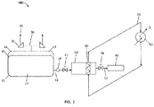
- the system 100 includes a pressure vessel or storage tank 10.
- the storage tank 10 is configured to store a liquefied fuel 20 such as hydrogen therein, which includes phases of liquid 22 and vapor 24.
- the vapor phase is in the headspace 23 of the tank 10.
- a pressure relief valve tree 30 including valves 32 is fluidly connected with the tank 10 in the headspace 23, and is used to release excessive vapor 26.
- the system 100 also includes a pump 34, a pressure vessel isolation valve 40, a dispenser 50, a heat exchanger 60, and a dispenser isolation valve 70.
- a vaporizer is implied in the dispenser 50 but not specifically shown.
- the tank 10, the pump 34, the pressure vessel isolation valve 40, the dispenser 50, and a dispenser isolation valve 70 are fluidly connected with each other. Pipe lines 12 may be used for the connection.
- the isolation valve 70 may be included as a portion of a nozzle, and is configured to add the gaseous fuel from the liquefied fuel to a receiving tank 80 in a vehicle.
- the heat exchanger 60 which may be known in the industry as a trim cooler that controls the final dispensing temperature to vehicle, is thermally coupled with the dispenser 50.
- the expected natural evaporation due to heat intrusion from the environment may be as high as 3% of nominal mass per day.
- MAWP maximum allowable working pressure
- such a storage tank or pressure vessel 10 must have the pressure relief valve tree 30 that provides the evaporated liquid, also known as boil-off 24, a pathway to the atmosphere to prevent the pressure from rising above the MAWP.
- the released extra boil-off or vapor phase 24 is labelled as excessive vapor 26.
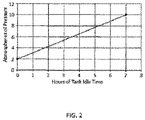
- the storage tank is 95% filled with liquid fuel to start, if the tank sits idle for 7 hours with no dispensing, the vapor pressure in the headspace 23 will rise from 2 atmospheres to 10 atmospheres. If the tank has an MAWP of 10 atmospheres, then the pressure relief valve tree 30 will have to vent 3%/day of the nominal storage mass in order to keep the tank at 10 atmospheres. For hydrogen fuel, this vapor will be vented at 32 Kelvin (K), thus such vented cold vapor is a significant waste.
- K Kelvin
- the fueling process needs to occur as close to -40 °C as possible.
- the dispenser 50 warms up to ambient temperature, which is above the desired dispensing temperature range of between 0 and -40 °C.
- the refrigeration unit 90 will have to "ramp-up" to full capacity in order to refrigerate the fuel below ambient temperature, which results in lag time, during which the fuel is warmer than the desired dispensing temperature.
- boil-off vapor is released to the atmosphere at 32 K.
- the present disclosure provides a system and a method, which utilize the accumulated boil-off vapor 24 in vapor headspace 23 to pre-cool the dispenser 50 in accordance with some embodiments. This pre-cooling enables fast startup which is defined as cooling the dispensed fuel to between 0 and -40 °C within 30 seconds from the start of dispensing.
- the cold vapor 24 from the storage tank 10 is delivered through at least a part of the dispenser 50.
- the cold boil-off vapor 24 will cool the dispenser when the dispenser is in-between fueling events.
- the cold vapor 24 is directed through the normal flow path that the fuel takes through the dispenser 50, thus pre-cooling the dispenser by direct contact between the dispenser 50 and the cold vapor 24.
- the cold boil-off vapor 24 travels through the heat exchanger 60 in the refrigeration system 90 and pre-cools the refrigeration system 90.
- FIG. 3 and FIG. 4 are for illustration only. The first and second exemplary systems in FIGS. 3-4 could be combined to pre-cool both the fuel dispensing flow path and the refrigeration system.
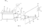
- the first exemplary system 200 is used for dispensing a gaseous fuel (e.g., H 2 ) from a liquefied fuel.
- exemplary system 200 comprises a storage tank 10, a dispenser 50, a heat exchanger 60, a pressure sensor 122, a vapor supply unit 125, and a temperature sensor 126.
- the storage tank 10 is configured to store a liquefied fuel 20 therein.
- the liquefied fuel 20 comprises phases of liquid 22 and vapor 24.
- the vapor 24 is in the headspace 23 as described above.
- a pressure relief valve tree 30 including valves 32 is fluidly connected with the tank 10 in the headspace 23, and is used to release excessive vapor 26.
- the pressure sensor 122 is coupled to the storage tank 10 and configured to measure a vapor pressure inside the storage tank 10.
- the exemplary system 200 further comprises a pump 34 and a first isolation valve 40 fluidly coupled with the storage tank 10, and is also fluidly connected with the dispenser 50. All the components fluidly coupled together are connected through suitable connection lines 12.
- the pump 34 and the first isolation valve 40 are configured to provide the liquefied fuel 20 in the liquid phase to the dispenser 50. After being pumped, the liquefied fuel 20 may be in a supercritical state.
- the dispenser 50 is configured to receive the liquefied fuel 20 from the storage tank 10. Such a liquefied fuel may be in a supercritical state.
- a heat exchanger 60 is thermally coupled with the dispenser 50 and configured to convert the liquid phase 22 of the liquefied fuel 20 in the dispenser 50 to a gaseous fuel.
- the dispenser 50 is configured to dispense the gaseous fuel to a receiving fuel tank 80 in a vehicle.
- the dispenser 50 is configured to regulate temperature, pressure, and mass flow rate of the gaseous fuel to the receiving fuel tank 80.
- the temperature sensor 126 is coupled to the dispenser 50 and configured to measure temperature of the dispenser 50.
- the vapor supply unit 125 is fluidly coupled with the storage tank 10 and configured to provide the vapor 24 of the liquefied fuel 20 from the storage tank 10 into the dispenser 50 or in thermally contact with at least one portion of the dispenser 50 so as to pre-cool the dispenser 50 before a refueling process.
- the vapor supply unit 125 is configured to adjust flow rate of the vapor 24 of the liquefied fuel 20 so as to maintain the vapor pressure inside the storage tank 10 and the temperature of the dispenser 50 within predetermined ranges.
- the vapor supply unit 125 comprises a second isolation valve 120 and suitable connections 124.
- the second isolation valve 120 is configured to adjust the flow rate of the vapor 24 of the liquefied fuel 20 going into the dispenser 50 or going to contact at least one portion of the dispenser 50. The adjustment is based on the inputs of the vapor pressure inside the storage tank 10 and the temperature of the dispenser 50.
- the second isolation valve 120 is a cryogenic valve with long stems, and can be actuated either manually or automatically. Such valves can be available from suppliers such as ACME Cryogenics Inc. of Pennsylvania, U.S.
- the exemplary system 200 may further comprise an electronic controller 130 electronically connected with at least the pressure sensor 122 and the temperature sensor 126, and configured to adjust the flow rate of the vapor 24 of the liquefied fuel 20 through the second isolation valve 120 based on the vapor pressure inside the storage tank 10 and the temperature of the dispenser 50 within predetermined ranges.
- the electronic controller 130 may be electronically connected with other components, and such electronic connections may be through wire connection, wireless connection, and may include cloud based connection.
- the electronic controller 130 and all the sensors can be also connected to an industrial control such as a programmable logic controller (PLC), which is supervised by a supervisory control and data acquisition (SCADA) computer with a human-machine interface (HMI).
- PLC programmable logic controller
- SCADA supervisory control and data acquisition
- HMI human-machine interface
- the SCADA computer is versatile and can be programmed to have easy-use features.
- the exemplary system 200 further comprises a refrigeration unit 90 fluidly coupled with the heat exchanger 60 through connection lines 92 with refrigerant inside.
- the heat exchanger 60 and/or the refrigeration unit 90 are configured to adjust the temperature of the dispenser 50 before or during a refueling process.
- the heat exchanger 60 is integrally coupled with the dispenser 50 and disposed inside the dispenser 50.
- the refrigerant inside the heat exchanger 60 does not contact or mix with the fuel inside the dispenser 50.
- the vapor supply unit 125 is configured to supply the vapor of the liquefied fuel from the storage tank 10 into the dispenser 50. As illustrated in FIG. 3 , the vapor 24 is used to directly cool the disperser 50.
- the vapor supply unit 125 includes no pump or compressor in a path of a vapor from the storage tank 10 to the dispenser 50.
- a suitable liquefied fuel 20 examples include, but are not limited to liquefied hydrogen, which may include a liquid phase 22, a vapor phase 24, or a combination thereof.
- the liquefied fuel 20 comprises or is liquid hydrogen.
- the fuel is stored as liquid hydrogen in a storage tank 10 and is dispersed as a gaseous hydrogen in a vehicle.
- the accumulated cold boil-off vapor 24 from the storage tank 10 is conducted through the dispenser 50 via automatic operation of the cold boil-off isolation valve 120.
- the cold boil-off vapor 24 cools the dispenser 50 by direct contact through a short burst of flow, which may be is released to the atmosphere by a vent valve or can be combined into the gaseous fuel to be added into a vehicle.
- each system described herein may include more than one dispenser 50 for refueling multiple vehicles at the same time.
- Table 1 shows the effectiveness of using liquid hydrogen boil-off to cool fuel dispenser(s).
- Table 1 shows how a 1,000 kg pressure vessel fuel storage tank 10 containing liquid hydrogen can supply enough refrigeration by means of natural evaporation to cool 1 or 2 dispensers.
- the dispenser is pre-cooled to -40 °C in 8.6 seconds.
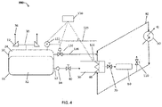
- a second exemplary system 300 is illustrated.
- the cold boil-off vapor 24 is used to pre-cool the refrigeration unit 90 and heat exchanger 60 through direct cooling.
- the exemplary system 300 is the same as the exemplary system 200, except the pre-cooling unit.
- the vapor supply unit 125 is configured to supply the vapor 24 of the liquefied fuel 20 into a circulation line 92 of the heat exchanger 60 and/or the refrigeration unit 90.
- the vapor 24 can be flushed into the refrigeration unit and circuited to the heat exchanger 60 before each refueling process.
- the vapor can be used in combination with a refrigerant in the refrigeration unit 90, and work together with the heat exchanger 60 to cool the dispenser 50 before and/or during a refueling process.
- the vapor 24 may be supplied to the circulation line 92 to cool the refrigeration unit 90 only without going into the heat exchanger 60.
- the vapor 24 can be released by a vent valve 110 before going into the heat exchanger 60.
- the accumulated cold boil-off vapor 24 from the storage tank 10 is conducted through the refrigeration unit 90 by automatic operation of cold boil-off isolation valve 120.
- the cold boil-off vapor 24 cools the refrigeration unit 90 and its circulation system by direct contact through a short burst of flow that is released to the atmosphere by a vent valve 110.
- the present disclosure provides a system having the combined features of the exemplary systems 200 and 300.
- One stream of the boil-off vapor 24 can be directly supplied into the disperser 50.
- Another stream of the boil-off vapor 24 can be a circulation line of the refrigeration unit 90 and the heat exchanger 60.
- an exemplary method 500 may comprise the following generalized steps.
- a liquefied fuel 20 stored inside a storage tank 10 is provided.
- the liquefied fuel 20 comprises phases of liquid 22 and vapor 24. Natural evaporation in the storage tank 10 produces pressure in the vapor 24 in the head space 23.
- a vapor pressure inside the storage tank 10 is measured using the pressure sensor 122 coupled to the storage tank 10.
- the temperature inside the dispenser 50 is measured using the temperature sensor 126 coupled to the dispenser 50.
- the pump 34, the first isolation valve 40, and the dispenser 50 are fluidly coupled with the storage tank 10.
- the heat exchanger 60 is thermally coupled with the dispenser 50 and configured to convert the liquefied fuel 20 in the dispenser 50 to a gaseous fuel.
- the dispenser 50 is configured to dispense the gaseous fuel to a receiving fuel tank 80 in a vehicle.
- the dispenser 50 is configured to regulate temperature, pressure, and mass flow rate of the gaseous fuel to the receiving fuel tank 80.
- the dispenser 50 is pre-cooled before a refueling process using a vapor supply unit 125 fluidly coupled with the storage tank 10.
- the vapor supply unit 125 provides the vapor 24 of the liquefied fuel 20 from the storage tank 10 into the dispenser 50 or in thermally contact with at least one portion of the dispenser 50 as described above.
- the boil-off 24 from natural evaporation may directed through the dispenser 50 or in a circulation line for the heat exchanger 60 and the refrigeration unit 90 dispensers 50 so that the vapor 24 is thermally in contact with the dispenser 50.
- the vapor 24 may be supplied in a short burst of flow. For example, within less than 30 seconds, for example, 8.6 seconds as described in Table 1, the dispenser 50 is pre-cooled to below ambient temperature.
- the boil-off 24 may be directed to the atmosphere via vent valve 110 instead of the pressure valve relief tree 30.
- the method 500 may further comprise a step 512 of adjusting a flow rate of the vapor 24 of the liquefied fuel 20 through a second isolation valve 120 in the vapor supply unit 125 so as to maintain the vapor pressure inside the storage tank 10 and the temperature of the dispenser 50 within predetermined ranges.
- a step of adjustment is performed using the 130 electronic control unit, according to the vapor pressure inside the storage tank 10 and the temperature of the dispenser 50 as the input parameters.
- the pressure of the storage tank 10 is maintained below a pressure relief valve setting.
- the gaseous fuel from the liquefied fuel 20 is dispensed into a receiving fuel tank 80 in a vehicle through the dispenser 50 in the refueling process. More than one dispensers 50 can be used to refuel multiple vehicles simultaneously in some embodiments.
- the method disclosed herein allows the cold boil-off vapor 24 from the storage tank 10 to be utilized as a refrigerant.
- the boil-off vapor 24 can be also used to refrigerate the fuel dispenser equipment in order to pre-cool the dispenser 50 in between fueling events.
- the dispenser 50 is pre-cooled so that the refueling process can be performed very quickly under the temperature and pressure specified based on the standard SAE J2601.
- the dispenser 50 is pre-cooled to provide a start-up time within a time limit selected the group consisting of 10 minutes, 9 minutes, 7 minutes, 6 minutes, 5 minutes, 4 minutes, and 3 minutes.
- the start-up time can be within 10 minutes, or within 5 minutes, or within 3 minutes.
- the start-up time is the time of starting up a refueling process following SAE 2601.
- the gaseous fuel is dispensed in a temperature of the dispenser 50 in a range from 0 °C to -40 °C. In some embodiments, the gaseous fuel is dispensed at a pressure being 350 bar (35 MPa) or 700 bar (70 MPa) and the dispenser 50 starts up within 10 minutes.
- the method includes a step 516 or steps of adjusting the temperature of the dispenser 50 before or during a refueling process using a heat exchanger 60 thermally coupled with the dispenser 50, and a refrigeration unit 90 fluidly coupled with the heat exchanger 60.
- the vapor 24 of the liquefied fuel 20 from the storage tank 10 may be provided into a circulation line of the heat exchanger.
- the liquefied fuel comprises or is hydrogen, and the dispenser 50 starts up within 3 minutes.
- the pre-cooling is performed using the boil-off vapor 24 before a refueling process
- the step of cooling the dispenser 50 during the refueling process is performed using the refrigerant going from the refrigeration unit 90 through the heat exchanger 60.
- the methods and system described herein may be at least partially embodied in the form of computer-implemented processes and apparatus for practicing those processes.
- the disclosed methods may also be at least partially embodied in the form of tangible, non-transient machine readable storage media encoded with computer program code, for example, in the control unit 130.
- the media may include, for example, RAMs, ROMs, CD-ROMs, DVD-ROMs, BD-ROMs, hard disk drives, flash memories, or any other non-transient machine-readable storage medium, or any combination of these mediums, wherein, when the computer program code is loaded into and executed by a computer, the computer becomes an apparatus for practicing the method.
- the methods may also be at least partially embodied in the form of a computer into which computer program code is loaded and/or executed, such that, the computer becomes an apparatus for practicing the methods.
- the computer program code segments configure the processor to create specific logic circuits.
- the methods may alternatively be at least partially embodied in a digital signal processor formed of application specific integrated circuits for performing the methods.
- the computer or the control unit may be operated remotely using a cloud based system.
Landscapes
- Engineering & Computer Science (AREA)
- Mechanical Engineering (AREA)
- General Engineering & Computer Science (AREA)
- Health & Medical Sciences (AREA)
- Public Health (AREA)
- Water Supply & Treatment (AREA)
- Filling Or Discharging Of Gas Storage Vessels (AREA)
Applications Claiming Priority (1)
| Application Number | Priority Date | Filing Date | Title |
|---|---|---|---|
| US17/135,366 US11649156B2 (en) | 2020-12-28 | 2020-12-28 | System and method for pre-cooling fuel dispenser |
Publications (2)
| Publication Number | Publication Date |
|---|---|
| EP4019824A1 true EP4019824A1 (de) | 2022-06-29 |
| EP4019824B1 EP4019824B1 (de) | 2023-11-15 |
Family
ID=74418223
Family Applications (1)
| Application Number | Title | Priority Date | Filing Date |
|---|---|---|---|
| EP21154230.3A Active EP4019824B1 (de) | 2020-12-28 | 2021-01-29 | System und verfahren zur vorkühlung einer benzinzapfsäule |
Country Status (3)
| Country | Link |
|---|---|
| US (1) | US11649156B2 (de) |
| EP (1) | EP4019824B1 (de) |
| CN (1) | CN114688451B (de) |
Families Citing this family (4)
| Publication number | Priority date | Publication date | Assignee | Title |
|---|---|---|---|---|
| DE102021202900A1 (de) * | 2021-03-24 | 2022-09-29 | Magna Steyr Fahrzeugtechnik Ag & Co Kg | Flüssigwasserstoffspeicher |
| US12405594B2 (en) * | 2021-09-02 | 2025-09-02 | L'air Liquide, Societe Anonyme Pour L'etude Et L'exploitation Des Procedes Georges Claude | Pumping of liquid cryogen from a storage tank |
| CN116291973B (zh) * | 2023-05-23 | 2023-07-28 | 北京航天试验技术研究所 | 一种火箭液氢箱自增压模拟及验证装置 |
| US20260028217A1 (en) * | 2024-07-26 | 2026-01-29 | Fca Us Llc | System and method for refueling hydrogen vehicles |
Citations (5)
| Publication number | Priority date | Publication date | Assignee | Title |
|---|---|---|---|---|
| US6619336B2 (en) | 2002-02-14 | 2003-09-16 | Air Products And Chemicals, Inc. | System and method for dispensing pressurized gas |
| EP2175187A2 (de) * | 2008-10-09 | 2010-04-14 | Linde Aktiengesellschaft | Betanken von Fahrzeugen mit unter Druck stehenden, gasförmigen Medien |
| DE102009037108A1 (de) * | 2009-08-11 | 2011-02-17 | Linde Aktiengesellschaft | Befüllen eines Speicherbehälters mit einem verdichteten Medium |
| US20190331298A1 (en) * | 2018-04-26 | 2019-10-31 | Chart Inc. | Cryogenic Fluid Dispensing System Having a Chilling Reservoir |
| US10655784B2 (en) * | 2015-10-02 | 2020-05-19 | Kobe Steel, Ltd. | Gas supply device and gas supply method |
Family Cites Families (9)
| Publication number | Priority date | Publication date | Assignee | Title |
|---|---|---|---|---|
| CA2401926C (en) * | 2002-09-06 | 2004-11-23 | Westport Research Inc. | Combined liquefied gas and compressed gas re-fueling station and method of operating a combined liquefied gas and compressed gas re-fueling station |
| DE102009037109A1 (de) | 2009-08-11 | 2011-02-17 | Linde Aktiengesellschaft | Befüllen eines Speicherbehälters mit einem verdichteten Medium |
| CA2796794C (en) * | 2012-11-23 | 2015-06-16 | Westport Power Inc. | Method and system for delivering a gaseous fuel into the air intake system of an internal combustion engine |
| CA2833619C (en) * | 2013-11-21 | 2020-06-30 | Westport Power Inc. | Method and system for delivering a gaseous fuel into the air intake system of an internal combustion engine |
| DE102014015987A1 (de) | 2014-10-28 | 2016-04-28 | Linde Aktiengesellschaft | Boil-Off-Gas-Management an Wasserstoff-Tankstellen |
| CN107614962B (zh) * | 2015-04-30 | 2020-09-11 | 西港能源有限公司 | 用于低温流体系统的智能压力管理系统 |
| DK201600136A1 (en) * | 2016-03-02 | 2017-10-02 | Nel Hydrogen As | Cooling of a supply pipe in a hydrogen refueling system |
| US11009185B2 (en) * | 2018-11-16 | 2021-05-18 | China Energy Investment Corporation Limited | Method and system of dispensing liquefied gas |
| US10760506B2 (en) * | 2019-02-06 | 2020-09-01 | Caterpillar Inc. | Liquified gaseous fuel storage tank level calibration control system |
-
2020
- 2020-12-28 US US17/135,366 patent/US11649156B2/en active Active
-
2021
- 2021-01-28 CN CN202110116946.4A patent/CN114688451B/zh active Active
- 2021-01-29 EP EP21154230.3A patent/EP4019824B1/de active Active
Patent Citations (5)
| Publication number | Priority date | Publication date | Assignee | Title |
|---|---|---|---|---|
| US6619336B2 (en) | 2002-02-14 | 2003-09-16 | Air Products And Chemicals, Inc. | System and method for dispensing pressurized gas |
| EP2175187A2 (de) * | 2008-10-09 | 2010-04-14 | Linde Aktiengesellschaft | Betanken von Fahrzeugen mit unter Druck stehenden, gasförmigen Medien |
| DE102009037108A1 (de) * | 2009-08-11 | 2011-02-17 | Linde Aktiengesellschaft | Befüllen eines Speicherbehälters mit einem verdichteten Medium |
| US10655784B2 (en) * | 2015-10-02 | 2020-05-19 | Kobe Steel, Ltd. | Gas supply device and gas supply method |
| US20190331298A1 (en) * | 2018-04-26 | 2019-10-31 | Chart Inc. | Cryogenic Fluid Dispensing System Having a Chilling Reservoir |
Also Published As
| Publication number | Publication date |
|---|---|
| US20220204337A1 (en) | 2022-06-30 |
| EP4019824B1 (de) | 2023-11-15 |
| CN114688451A (zh) | 2022-07-01 |
| CN114688451B (zh) | 2024-08-30 |
| US11649156B2 (en) | 2023-05-16 |
Similar Documents
| Publication | Publication Date | Title |
|---|---|---|
| EP4019824B1 (de) | System und verfahren zur vorkühlung einer benzinzapfsäule | |
| US11499675B2 (en) | Method and facility for storing and distributing liquefied hydrogen | |
| US10961109B2 (en) | Fluid bypass method and system for controlling the temperature of a non-petroleum fuel | |
| KR102566242B1 (ko) | 액화가스를 분배하는 방법 및 시스템 | |
| US8671997B2 (en) | Device and method for filling a container with a gas under pressure | |
| US9458968B2 (en) | Hydrogen dispensing process and system | |
| US20190137041A1 (en) | Method and device for filling a high pressure storage tank | |
| EP3759564B1 (de) | Mobiler wasserstoffspender für brennstoffzellenfahrzeuge | |
| CN107923669A (zh) | 在三相点处用制冷剂冷却流体 | |
| US20230067726A1 (en) | Pumping of liquid cryogen from a storage tank | |
| KR20210006289A (ko) | 액체 수소의 제조를 위한 공정 및 플랜트 | |
| EP4023928B1 (de) | Verfahren zur minimierung des leistungsbedarfs für eine wasserstofftankstelle | |
| CN108700258B (zh) | 用于冷却第一低温压力容器的方法和具有压力容器系统的机动车 | |
| US10415509B2 (en) | Cooling system for cryogenic fuel delivery components | |
| JP2017032122A (ja) | 水素プレクールシステム | |
| US7484540B2 (en) | Liquid hydrogen storage tank with reduced tanking losses | |
| US10358148B2 (en) | System and method for reducing vapor generation in liquefied natural gas fueled vehicle | |
| CN113790389B (zh) | 加氢站冷水机组冷冻水流量调节方法及系统 | |
| US20060130896A1 (en) | High reliability gas mixture back-up system |
Legal Events
| Date | Code | Title | Description |
|---|---|---|---|
| STAA | Information on the status of an ep patent application or granted ep patent |
Free format text: STATUS: EXAMINATION IS IN PROGRESS |
|
| PUAI | Public reference made under article 153(3) epc to a published international application that has entered the european phase |
Free format text: ORIGINAL CODE: 0009012 |
|
| 17P | Request for examination filed |
Effective date: 20210930 |
|
| AK | Designated contracting states |
Kind code of ref document: A1 Designated state(s): AL AT BE BG CH CY CZ DE DK EE ES FI FR GB GR HR HU IE IS IT LI LT LU LV MC MK MT NL NO PL PT RO RS SE SI SK SM TR |
|
| GRAP | Despatch of communication of intention to grant a patent |
Free format text: ORIGINAL CODE: EPIDOSNIGR1 |
|
| STAA | Information on the status of an ep patent application or granted ep patent |
Free format text: STATUS: GRANT OF PATENT IS INTENDED |
|
| INTG | Intention to grant announced |
Effective date: 20230510 |
|
| GRAJ | Information related to disapproval of communication of intention to grant by the applicant or resumption of examination proceedings by the epo deleted |
Free format text: ORIGINAL CODE: EPIDOSDIGR1 |
|
| STAA | Information on the status of an ep patent application or granted ep patent |
Free format text: STATUS: EXAMINATION IS IN PROGRESS |
|
| GRAP | Despatch of communication of intention to grant a patent |
Free format text: ORIGINAL CODE: EPIDOSNIGR1 |
|
| STAA | Information on the status of an ep patent application or granted ep patent |
Free format text: STATUS: GRANT OF PATENT IS INTENDED |
|
| GRAS | Grant fee paid |
Free format text: ORIGINAL CODE: EPIDOSNIGR3 |
|
| INTC | Intention to grant announced (deleted) | ||
| GRAA | (expected) grant |
Free format text: ORIGINAL CODE: 0009210 |
|
| STAA | Information on the status of an ep patent application or granted ep patent |
Free format text: STATUS: THE PATENT HAS BEEN GRANTED |
|
| INTG | Intention to grant announced |
Effective date: 20231004 |
|
| AK | Designated contracting states |
Kind code of ref document: B1 Designated state(s): AL AT BE BG CH CY CZ DE DK EE ES FI FR GB GR HR HU IE IS IT LI LT LU LV MC MK MT NL NO PL PT RO RS SE SI SK SM TR |
|
| REG | Reference to a national code |
Ref country code: CH Ref legal event code: EP Ref country code: GB Ref legal event code: FG4D |
|
| REG | Reference to a national code |
Ref country code: DE Ref legal event code: R096 Ref document number: 602021006719 Country of ref document: DE |
|
| REG | Reference to a national code |
Ref country code: IE Ref legal event code: FG4D |
|
| REG | Reference to a national code |
Ref country code: LT Ref legal event code: MG9D |
|
| REG | Reference to a national code |
Ref country code: NL Ref legal event code: MP Effective date: 20231115 |
|
| PG25 | Lapsed in a contracting state [announced via postgrant information from national office to epo] |
Ref country code: GR Free format text: LAPSE BECAUSE OF FAILURE TO SUBMIT A TRANSLATION OF THE DESCRIPTION OR TO PAY THE FEE WITHIN THE PRESCRIBED TIME-LIMIT Effective date: 20240216 |
|
| PG25 | Lapsed in a contracting state [announced via postgrant information from national office to epo] |
Ref country code: IS Free format text: LAPSE BECAUSE OF FAILURE TO SUBMIT A TRANSLATION OF THE DESCRIPTION OR TO PAY THE FEE WITHIN THE PRESCRIBED TIME-LIMIT Effective date: 20240315 |
|
| PG25 | Lapsed in a contracting state [announced via postgrant information from national office to epo] |
Ref country code: LT Free format text: LAPSE BECAUSE OF FAILURE TO SUBMIT A TRANSLATION OF THE DESCRIPTION OR TO PAY THE FEE WITHIN THE PRESCRIBED TIME-LIMIT Effective date: 20231115 |
|
| REG | Reference to a national code |
Ref country code: AT Ref legal event code: MK05 Ref document number: 1632076 Country of ref document: AT Kind code of ref document: T Effective date: 20231115 |
|
| PG25 | Lapsed in a contracting state [announced via postgrant information from national office to epo] |
Ref country code: NL Free format text: LAPSE BECAUSE OF FAILURE TO SUBMIT A TRANSLATION OF THE DESCRIPTION OR TO PAY THE FEE WITHIN THE PRESCRIBED TIME-LIMIT Effective date: 20231115 |
|
| PG25 | Lapsed in a contracting state [announced via postgrant information from national office to epo] |
Ref country code: AT Free format text: LAPSE BECAUSE OF FAILURE TO SUBMIT A TRANSLATION OF THE DESCRIPTION OR TO PAY THE FEE WITHIN THE PRESCRIBED TIME-LIMIT Effective date: 20231115 |
|
| PG25 | Lapsed in a contracting state [announced via postgrant information from national office to epo] |
Ref country code: ES Free format text: LAPSE BECAUSE OF FAILURE TO SUBMIT A TRANSLATION OF THE DESCRIPTION OR TO PAY THE FEE WITHIN THE PRESCRIBED TIME-LIMIT Effective date: 20231115 |
|
| PG25 | Lapsed in a contracting state [announced via postgrant information from national office to epo] |
Ref country code: NL Free format text: LAPSE BECAUSE OF FAILURE TO SUBMIT A TRANSLATION OF THE DESCRIPTION OR TO PAY THE FEE WITHIN THE PRESCRIBED TIME-LIMIT Effective date: 20231115 Ref country code: LT Free format text: LAPSE BECAUSE OF FAILURE TO SUBMIT A TRANSLATION OF THE DESCRIPTION OR TO PAY THE FEE WITHIN THE PRESCRIBED TIME-LIMIT Effective date: 20231115 Ref country code: IS Free format text: LAPSE BECAUSE OF FAILURE TO SUBMIT A TRANSLATION OF THE DESCRIPTION OR TO PAY THE FEE WITHIN THE PRESCRIBED TIME-LIMIT Effective date: 20240315 Ref country code: GR Free format text: LAPSE BECAUSE OF FAILURE TO SUBMIT A TRANSLATION OF THE DESCRIPTION OR TO PAY THE FEE WITHIN THE PRESCRIBED TIME-LIMIT Effective date: 20240216 Ref country code: ES Free format text: LAPSE BECAUSE OF FAILURE TO SUBMIT A TRANSLATION OF THE DESCRIPTION OR TO PAY THE FEE WITHIN THE PRESCRIBED TIME-LIMIT Effective date: 20231115 Ref country code: BG Free format text: LAPSE BECAUSE OF FAILURE TO SUBMIT A TRANSLATION OF THE DESCRIPTION OR TO PAY THE FEE WITHIN THE PRESCRIBED TIME-LIMIT Effective date: 20240215 Ref country code: AT Free format text: LAPSE BECAUSE OF FAILURE TO SUBMIT A TRANSLATION OF THE DESCRIPTION OR TO PAY THE FEE WITHIN THE PRESCRIBED TIME-LIMIT Effective date: 20231115 Ref country code: PT Free format text: LAPSE BECAUSE OF FAILURE TO SUBMIT A TRANSLATION OF THE DESCRIPTION OR TO PAY THE FEE WITHIN THE PRESCRIBED TIME-LIMIT Effective date: 20240315 |
|
| PG25 | Lapsed in a contracting state [announced via postgrant information from national office to epo] |
Ref country code: SE Free format text: LAPSE BECAUSE OF FAILURE TO SUBMIT A TRANSLATION OF THE DESCRIPTION OR TO PAY THE FEE WITHIN THE PRESCRIBED TIME-LIMIT Effective date: 20231115 Ref country code: RS Free format text: LAPSE BECAUSE OF FAILURE TO SUBMIT A TRANSLATION OF THE DESCRIPTION OR TO PAY THE FEE WITHIN THE PRESCRIBED TIME-LIMIT Effective date: 20231115 Ref country code: PL Free format text: LAPSE BECAUSE OF FAILURE TO SUBMIT A TRANSLATION OF THE DESCRIPTION OR TO PAY THE FEE WITHIN THE PRESCRIBED TIME-LIMIT Effective date: 20231115 Ref country code: NO Free format text: LAPSE BECAUSE OF FAILURE TO SUBMIT A TRANSLATION OF THE DESCRIPTION OR TO PAY THE FEE WITHIN THE PRESCRIBED TIME-LIMIT Effective date: 20240215 Ref country code: LV Free format text: LAPSE BECAUSE OF FAILURE TO SUBMIT A TRANSLATION OF THE DESCRIPTION OR TO PAY THE FEE WITHIN THE PRESCRIBED TIME-LIMIT Effective date: 20231115 Ref country code: HR Free format text: LAPSE BECAUSE OF FAILURE TO SUBMIT A TRANSLATION OF THE DESCRIPTION OR TO PAY THE FEE WITHIN THE PRESCRIBED TIME-LIMIT Effective date: 20231115 |
|
| PG25 | Lapsed in a contracting state [announced via postgrant information from national office to epo] |
Ref country code: DK Free format text: LAPSE BECAUSE OF FAILURE TO SUBMIT A TRANSLATION OF THE DESCRIPTION OR TO PAY THE FEE WITHIN THE PRESCRIBED TIME-LIMIT Effective date: 20231115 |
|
| PG25 | Lapsed in a contracting state [announced via postgrant information from national office to epo] |
Ref country code: CZ Free format text: LAPSE BECAUSE OF FAILURE TO SUBMIT A TRANSLATION OF THE DESCRIPTION OR TO PAY THE FEE WITHIN THE PRESCRIBED TIME-LIMIT Effective date: 20231115 |
|
| PG25 | Lapsed in a contracting state [announced via postgrant information from national office to epo] |
Ref country code: SK Free format text: LAPSE BECAUSE OF FAILURE TO SUBMIT A TRANSLATION OF THE DESCRIPTION OR TO PAY THE FEE WITHIN THE PRESCRIBED TIME-LIMIT Effective date: 20231115 |
|
| PG25 | Lapsed in a contracting state [announced via postgrant information from national office to epo] |
Ref country code: SM Free format text: LAPSE BECAUSE OF FAILURE TO SUBMIT A TRANSLATION OF THE DESCRIPTION OR TO PAY THE FEE WITHIN THE PRESCRIBED TIME-LIMIT Effective date: 20231115 Ref country code: SK Free format text: LAPSE BECAUSE OF FAILURE TO SUBMIT A TRANSLATION OF THE DESCRIPTION OR TO PAY THE FEE WITHIN THE PRESCRIBED TIME-LIMIT Effective date: 20231115 Ref country code: RO Free format text: LAPSE BECAUSE OF FAILURE TO SUBMIT A TRANSLATION OF THE DESCRIPTION OR TO PAY THE FEE WITHIN THE PRESCRIBED TIME-LIMIT Effective date: 20231115 Ref country code: IT Free format text: LAPSE BECAUSE OF FAILURE TO SUBMIT A TRANSLATION OF THE DESCRIPTION OR TO PAY THE FEE WITHIN THE PRESCRIBED TIME-LIMIT Effective date: 20231115 Ref country code: EE Free format text: LAPSE BECAUSE OF FAILURE TO SUBMIT A TRANSLATION OF THE DESCRIPTION OR TO PAY THE FEE WITHIN THE PRESCRIBED TIME-LIMIT Effective date: 20231115 Ref country code: DK Free format text: LAPSE BECAUSE OF FAILURE TO SUBMIT A TRANSLATION OF THE DESCRIPTION OR TO PAY THE FEE WITHIN THE PRESCRIBED TIME-LIMIT Effective date: 20231115 Ref country code: CZ Free format text: LAPSE BECAUSE OF FAILURE TO SUBMIT A TRANSLATION OF THE DESCRIPTION OR TO PAY THE FEE WITHIN THE PRESCRIBED TIME-LIMIT Effective date: 20231115 |
|
| REG | Reference to a national code |
Ref country code: DE Ref legal event code: R097 Ref document number: 602021006719 Country of ref document: DE |
|
| PG25 | Lapsed in a contracting state [announced via postgrant information from national office to epo] |
Ref country code: MC Free format text: LAPSE BECAUSE OF FAILURE TO SUBMIT A TRANSLATION OF THE DESCRIPTION OR TO PAY THE FEE WITHIN THE PRESCRIBED TIME-LIMIT Effective date: 20231115 |
|
| PG25 | Lapsed in a contracting state [announced via postgrant information from national office to epo] |
Ref country code: MC Free format text: LAPSE BECAUSE OF FAILURE TO SUBMIT A TRANSLATION OF THE DESCRIPTION OR TO PAY THE FEE WITHIN THE PRESCRIBED TIME-LIMIT Effective date: 20231115 |
|
| REG | Reference to a national code |
Ref country code: CH Ref legal event code: PL |
|
| PG25 | Lapsed in a contracting state [announced via postgrant information from national office to epo] |
Ref country code: LU Free format text: LAPSE BECAUSE OF NON-PAYMENT OF DUE FEES Effective date: 20240129 |
|
| PLBE | No opposition filed within time limit |
Free format text: ORIGINAL CODE: 0009261 |
|
| STAA | Information on the status of an ep patent application or granted ep patent |
Free format text: STATUS: NO OPPOSITION FILED WITHIN TIME LIMIT |
|
| PG25 | Lapsed in a contracting state [announced via postgrant information from national office to epo] |
Ref country code: LU Free format text: LAPSE BECAUSE OF NON-PAYMENT OF DUE FEES Effective date: 20240129 |
|
| PG25 | Lapsed in a contracting state [announced via postgrant information from national office to epo] |
Ref country code: BE Free format text: LAPSE BECAUSE OF NON-PAYMENT OF DUE FEES Effective date: 20240131 |
|
| PG25 | Lapsed in a contracting state [announced via postgrant information from national office to epo] |
Ref country code: CH Free format text: LAPSE BECAUSE OF NON-PAYMENT OF DUE FEES Effective date: 20240131 |
|
| 26N | No opposition filed |
Effective date: 20240819 |
|
| PG25 | Lapsed in a contracting state [announced via postgrant information from national office to epo] |
Ref country code: SI Free format text: LAPSE BECAUSE OF FAILURE TO SUBMIT A TRANSLATION OF THE DESCRIPTION OR TO PAY THE FEE WITHIN THE PRESCRIBED TIME-LIMIT Effective date: 20231115 |
|
| PG25 | Lapsed in a contracting state [announced via postgrant information from national office to epo] |
Ref country code: SI Free format text: LAPSE BECAUSE OF FAILURE TO SUBMIT A TRANSLATION OF THE DESCRIPTION OR TO PAY THE FEE WITHIN THE PRESCRIBED TIME-LIMIT Effective date: 20231115 Ref country code: CH Free format text: LAPSE BECAUSE OF NON-PAYMENT OF DUE FEES Effective date: 20240131 Ref country code: BE Free format text: LAPSE BECAUSE OF NON-PAYMENT OF DUE FEES Effective date: 20240131 |
|
| REG | Reference to a national code |
Ref country code: BE Ref legal event code: MM Effective date: 20240131 |
|
| PG25 | Lapsed in a contracting state [announced via postgrant information from national office to epo] |
Ref country code: IE Free format text: LAPSE BECAUSE OF NON-PAYMENT OF DUE FEES Effective date: 20240129 |
|
| PG25 | Lapsed in a contracting state [announced via postgrant information from national office to epo] |
Ref country code: IE Free format text: LAPSE BECAUSE OF NON-PAYMENT OF DUE FEES Effective date: 20240129 |
|
| PG25 | Lapsed in a contracting state [announced via postgrant information from national office to epo] |
Ref country code: CY Free format text: LAPSE BECAUSE OF FAILURE TO SUBMIT A TRANSLATION OF THE DESCRIPTION OR TO PAY THE FEE WITHIN THE PRESCRIBED TIME-LIMIT; INVALID AB INITIO Effective date: 20210129 |
|
| PG25 | Lapsed in a contracting state [announced via postgrant information from national office to epo] |
Ref country code: HU Free format text: LAPSE BECAUSE OF FAILURE TO SUBMIT A TRANSLATION OF THE DESCRIPTION OR TO PAY THE FEE WITHIN THE PRESCRIBED TIME-LIMIT; INVALID AB INITIO Effective date: 20210129 |
|
| PG25 | Lapsed in a contracting state [announced via postgrant information from national office to epo] |
Ref country code: FI Free format text: LAPSE BECAUSE OF FAILURE TO SUBMIT A TRANSLATION OF THE DESCRIPTION OR TO PAY THE FEE WITHIN THE PRESCRIBED TIME-LIMIT Effective date: 20231115 |
|
| PG25 | Lapsed in a contracting state [announced via postgrant information from national office to epo] |
Ref country code: TR Free format text: LAPSE BECAUSE OF FAILURE TO SUBMIT A TRANSLATION OF THE DESCRIPTION OR TO PAY THE FEE WITHIN THE PRESCRIBED TIME-LIMIT Effective date: 20231115 |
|
| PGFP | Annual fee paid to national office [announced via postgrant information from national office to epo] |
Ref country code: GB Payment date: 20260127 Year of fee payment: 6 |
|
| PGFP | Annual fee paid to national office [announced via postgrant information from national office to epo] |
Ref country code: DE Payment date: 20260114 Year of fee payment: 6 |
|
| PGFP | Annual fee paid to national office [announced via postgrant information from national office to epo] |
Ref country code: FR Payment date: 20260128 Year of fee payment: 6 |