EP4019929A1 - Système et procédé de sous-échantillonnage d'un sous-échantillon gazeux d'un fluide monophasique pour une analyse de gaz rare - Google Patents
Système et procédé de sous-échantillonnage d'un sous-échantillon gazeux d'un fluide monophasique pour une analyse de gaz rare Download PDFInfo
- Publication number
- EP4019929A1 EP4019929A1 EP20306665.9A EP20306665A EP4019929A1 EP 4019929 A1 EP4019929 A1 EP 4019929A1 EP 20306665 A EP20306665 A EP 20306665A EP 4019929 A1 EP4019929 A1 EP 4019929A1
- Authority
- EP
- European Patent Office
- Prior art keywords
- cell
- subsampling
- pressure
- fluid
- expandable
- Prior art date
- Legal status (The legal status is an assumption and is not a legal conclusion. Google has not performed a legal analysis and makes no representation as to the accuracy of the status listed.)
- Withdrawn
Links
Images


Classifications
-
- G—PHYSICS
- G01—MEASURING; TESTING
- G01N—INVESTIGATING OR ANALYSING MATERIALS BY DETERMINING THEIR CHEMICAL OR PHYSICAL PROPERTIES
- G01N1/00—Sampling; Preparing specimens for investigation
- G01N1/02—Devices for withdrawing samples
- G01N1/10—Devices for withdrawing samples in the liquid or fluent state
-
- G—PHYSICS
- G01—MEASURING; TESTING
- G01N—INVESTIGATING OR ANALYSING MATERIALS BY DETERMINING THEIR CHEMICAL OR PHYSICAL PROPERTIES
- G01N1/00—Sampling; Preparing specimens for investigation
- G01N1/02—Devices for withdrawing samples
- G01N1/22—Devices for withdrawing samples in the gaseous state
- G01N1/2247—Sampling from a flowing stream of gas
-
- G—PHYSICS
- G01—MEASURING; TESTING
- G01N—INVESTIGATING OR ANALYSING MATERIALS BY DETERMINING THEIR CHEMICAL OR PHYSICAL PROPERTIES
- G01N1/00—Sampling; Preparing specimens for investigation
- G01N1/02—Devices for withdrawing samples
- G01N1/22—Devices for withdrawing samples in the gaseous state
- G01N1/2294—Sampling soil gases or the like
-
- G—PHYSICS
- G01—MEASURING; TESTING
- G01N—INVESTIGATING OR ANALYSING MATERIALS BY DETERMINING THEIR CHEMICAL OR PHYSICAL PROPERTIES
- G01N1/00—Sampling; Preparing specimens for investigation
- G01N1/02—Devices for withdrawing samples
- G01N1/10—Devices for withdrawing samples in the liquid or fluent state
- G01N2001/1062—Sampling under constant temperature, pressure, or the like
-
- G—PHYSICS
- G01—MEASURING; TESTING
- G01N—INVESTIGATING OR ANALYSING MATERIALS BY DETERMINING THEIR CHEMICAL OR PHYSICAL PROPERTIES
- G01N1/00—Sampling; Preparing specimens for investigation
- G01N1/02—Devices for withdrawing samples
- G01N1/22—Devices for withdrawing samples in the gaseous state
- G01N1/2247—Sampling from a flowing stream of gas
- G01N2001/2267—Sampling from a flowing stream of gas separating gas from liquid, e.g. bubbles
Definitions
- the present invention relates to the field of chemical analysis.
- the invention relates to the preparation of samples for chemical analysis.
- This invention provides a new subsampling method and system for the preparation of a gaseous subsample from a monophasic fluid.
- the invention is particularly adapted to the preparation of a subsample for the analysis of noble gas abundances.
- Noble gases namely helium (He), neon (Ne), argon (Ar), krypton (Kr), and xenon (Xe), have proven to be powerful tools to better understand many geological processes due to their properties of low abundance and chemical inertness.
- noble gas studies play an important role in investigating earthquakes and volcanic activity, as well as for reconstructing paleoclimate conditions and interpreting ocean circulation histories.
- Noble gases are unaffected by inorganic or organic chemical reactions and only sensitive to physical processes. As noble gas are present under trace in all fluids and minerals, it makes them ideal tracers for investigating the origin and evolution of subsurface fluids, whatever water, oil and/or gas systems.
- noble gases in fluids are derived from three main sources, which are the atmosphere, crust, and mantle.
- the presence of noble gases in fluids and their relative abundances can provide new insights into surface or subsurface fluid evolution (e.g., fluid origins, fluid flow paths, fluid circulation, and fluid contamination).
- the noble gas elemental and isotope compositions in crustal fluids are critical for the understanding of the interactions among various crustal subsurface fluids (water, oil and gas).
- various crustal subsurface fluids water, oil and gas
- the measured atmospheric noble gases in oil and gas reservoirs can result from the interactions between groundwater and the hydrocarbon system.
- reservoir characterization it has been proposed to measure concentrations and isotopic ratios of noble gases present in a seep sample, which are measured and compared to a concentration of the formation water. Such a comparison allows the determination of a type, quality, hydrocarbon/water volume ratio, and/or volume of hydrocarbons associated with the subsurface accumulation ( WO2013148442 ).
- noble gas isotopes are powerful tracers of subsurface fluid provenance and can be used to understand the impact of enhanced oil recovery on hydrocarbon systems and potentially overlying aquifers.
- gas samples e.g., no heavy compounds that condense in the purification line
- a relatively low pressure to limit the number of molecules to be purified
- noble gas sampling system should avoid any air pollution.
- the invention aims to overcome the disadvantages of the prior art.
- the invention proposes a subsampling method and system, said method or system allowing the preparation of a gaseous subsample from a monophasic fluid that can be used for example for the noble gas abundance analysis.
- the pressure, volume and temperature conditions are fully controlled when the monophasic fluid is transformed in a diphasic fluid (i.e., bubble point pressure, PV curve).
- a diphasic fluid i.e., bubble point pressure, PV curve
- By knowing the precise condition when the bubble point occurred it is possible to accurately calculate the original noble gas signature of the monophasic fluid.
- monophasic liquid samples a split of the sample in diphasic domain under equilibrium and under controlled conditions of pressure and temperature enable an analyze dedicated to the gas phase to rebuild the initial fluid composition.
- a subsampling system of a monophasic fluid for the preparation of a gaseous subsample comprising:
- a system according to the invention allows the collection of an aliquot of a monophasic fluid. Such an aliquot is subject to pressure variation in the expandable cell until a bubble point occurs, the monophasic fluid becoming a diphasic fluid made of a liquid phase and a gas phase.
- the invention allows a phase split under controlled conditions in order to recombine the initial chemical content such as noble gas content of the initial monophasic fluid.
- a system according to the invention allows the preparation of representative samples of the monophasic fluid which are not fractionated. All steps are well constrained and the conditions of sampling are controlled and recorded; This allows a true determination of chemical content such as noble gas fingerprint of a monophasic fluid.
- subsampling system it can optionally include one or more of the following characteristics alone or in combination:
- a method of subsampling a monophasic fluid for the preparation of a gaseous subsample using a subsampling system comprising a first inlet valve, an expandable cell, a second valve, and an expansion cell; said subsampling method comprising:
- Such a method allows the subsampling of noble gases from a monophasic fluid, where the pressure, volume and temperature conditions are known and preferably volume and temperature are controlled. By knowing the precise condition in which the bubble point occurred, and the fluid properties it is possible to accurately calculate the original noble gas signature of the monophasic fluid.
- This method is particularly relevant for all noble gas studies that use monophasic liquids.
- Subsampling means or implies a procedure by which a smaller, representative sample is taken from a larger sample.
- a monophasic fluid corresponds to a particular state of a fluid having one phase which is liquid form or gas form, or supercritical form.
- a monophasic fluid corresponds to a state of a fluid having one phase which is liquid form.
- gaseous subsample is about collecting a fraction of a sample in a gas form
- low-pressure section means a section of a subsampling system configured to an operating pressure of less than 20 bar.
- high-pressure means a pressure higher than 20 bar
- a “high-pressure section” means a section of a subsampling system configured to an operating pressure of more than 20 bar.
- noble gases refers to a series of chemically inert elements that exhibit similar properties.
- the noble gases are a group of chemically inert, or conservative, gases which have a low natural abundance in natural fluids.
- Various physical processes have resulted in different pools of noble gases (the mantle, atmospheric and crustal pools) becoming distinct in their isotopic composition and relative elemental abundances.
- the five noble gases of particular interest in the present invention are helium (He), neon (Ne), argon (Ar), krypton (Kr) and xenon (Xe).
- process By “process”, “compute”, “determine”, “display”, “extract”, “compare” or more broadly “executable operation” is meant, within the meaning of the invention, an action performed by a computer device or a processor unless the context indicates otherwise.
- the operations relate to actions and/or processes of a data processing system, for example a computer system or an electronic computing device, which manipulates and transforms the data represented as physical (electronic) quantities in the memories of the computer system or other devices for storing, transmitting or displaying information.
- calculation operations are carried out by the processor of the device, the produced data are entered in a corresponding field in a data memory and this field or these fields can be returned to a user for example through a Human-Machine Interface formatting such data.
- These operations may be based on applications or software.
- application means any expression, code or notation, of a set of instructions intended to cause a data processing to perform a particular function directly or indirectly (for example after a conversion operation into another code).
- exemplary program codes may include, but are not limited to, a subprogram, a function, an executable application, a source code, an object code, a library and/or any other sequence of instructions designed for being performed on a computer system.
- processor is meant, within the meaning of the invention, at least one hardware circuit configured to perform operations according to instructions contained in a code.
- the hardware circuit may be an integrated circuit. Examples of a processor include, but are not limited to, a central processing unit, a graphics processor, an application-specific integrated circuit ("ASIC" according to Anglo-Saxon terminology), and a programmable logic circuit. A single processor or several other units may be used to implement the invention.
- Coupled is meant, within the meaning of the invention, connected, directly or indirectly, with one or more intermediate elements. Two elements may be coupled mechanically, electrically or linked by a communication channel.
- human-machine interface within the meaning of the invention, corresponds to any element allowing a human being to communicate with a computer, in particular and without that list being exhaustive, a keyboard and means allowing in response to the commands entered on the keyboard to perform displays and optionally to select with the mouse or a touchpad items displayed on the screen.
- a touch screen for selecting directly on the screen the elements touched by the finger or an object and optionally with the possibility of displaying a virtual keyboard.
- computer device any device comprising a processing unit or a processor, for example in the form of a microcontroller cooperating with a data memory, possibly a program memory, said memories possibly being dissociated.
- the processing unit cooperates with said memories by means of internal communication bus.
- references to "one embodiment” or “an embodiment” of the present disclosure are not intended to be interpreted as excluding the existence of additional embodiments that also incorporate the recited features.
- Chemical elements can partition differently between phases. Hence the analysis of a monophasic fluid sampled in extreme environment (i.e., pressure more than 20 bar or temperature > 100 °C) can be biased when the subsampling is not correctly done. To calculate the concentration of chemical elements, such as noble gas, in each phase at the time of sampling, several approximations are usually done, this leading to inaccurate results.
- PVT sampling bottles containing a complex fluid
- PVT sampling bottles are used through a pressure decrease to create gaseous samples.
- a generation of gaseous samples when it is done without any parameter control, lead to a degradation of the content of the sampling bottle and show a low reproduction rate.
- the inventors developed a new solution for isolating chemical elements, in particular noble gases, from complex fluids such as fluids containing water-gas-oil mixtures.
- the solution can be described as an offline extraction system configured to isolate a gaseous subsample from a high-pressure monophasic fluid.
- the invention thus relates to a method or system for obtaining a representative noble gas sample from a monophasic sample, where the precise pressure, volume and temperature conditions are known or controlled, allowing for the calculation of the original noble gas composition in a monophasic fluid.
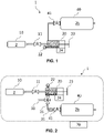
- the invention relates to a subsampling system 1 of a monophasic fluid 2.
- Such a subsampling system 1 is particularly relevant for the preparation of a gaseous subsample 2b from the monophasic fluid 2, said gaseous subsample being adapted to noble gas analysis.
- the subsampling system 1 comprises a first inlet valve 11, an expandable cell 20, a second valve 41, and an expansion cell 40.
- this subsampling system 1 can be used under various arrangements.
- this subsampling system 1 will comprise two main parts: a phase split part and a low-pressure part.
- the split part will in particular comprise the first inlet valve 11 and the expandable cell 20.
- This split part is configured to induce a phase split in the monophasic fluid 2 under highly controlled conditions. Indeed, the phase split is preferably monitored through temperature, volume, and pressure measurements.
- the low-pressure part will in particular comprise the expansion cell 40.
- This low-pressure part is configured to induce an expansion of the gaseous subsample and thus to reduce the pressure of this gaseous subsample under controlled conditions (e.g., a defined volume of the expansion cell 40).
- the first inlet valve 11 is preferably arranged so as to receive the monophasic fluid 2.
- the monophasic fluid 2 can be received through the first inlet valve 11 from a sampling bottle 10.
- the first inlet valve 11 is adapted to be connected to a PVT (Pressure, Volume, Temperature) sampling bottle.
- PVT Pressure, Volume, Temperature
- the invention relates to the subsampling of a gaseous phase of a monophasic fluid 2 sampled in an extreme environment such as a high-pressure environment.
- the monophasic fluid 2 is preferably maintained in a controlled environment reflecting the initial sampling conditions.
- the first inlet valve 11 is preferably configured to control the flow of the monophasic fluid 2 from the sampling bottle 10 to the expandable cell 20.
- the first inlet valve 11 is arranged to take a very low volume sample from the monophasic fluid source.
- the system is arranged so that the first inlet valve 11 is capable of transferring an aliquot of less than 10 cc from the monophasic fluid source, preferably less than 5 cc, more preferably less than 1 cc.
- the first inlet valve 11 can be a two-way or a three-way inlet valve. It can be selected from automated or manual valves. For example, the use of pneumatically actuated inlet valves enables full automation of subsample preparation and eventually post-analysis clean up.
- the first inlet valve 11 has to be designed to support a pressure ranging from 10 -7 mbar to 1000 bars.
- the subsampling system 1 also comprises an expandable cell 20.
- the expandable cell 20 is thermoregulated and the pressure in the expandable cell 20 is monitored.
- the expandable cell 20 has the particularity to be arranged to allow a controlled and variable expansion of the monophasic fluid 2.
- the controlled and variable expansion of this expandable cell 20, in particular of its inner volume, can be managed through various ways, for example using a movable inner surface like a movable piston or a movable wall such as in a syringe cell.
- a movable inner surface that can be moved through the use of a fluid controlled by one or several valves.
- the expandable cell can be composed of different chambers separated with valves and the expansion is controlled by the connection of the initial volume to additional volumes of supplementary chambers.
- the expandable cell 20 can be equipped with at least one movable surface such as a piston 23, preferably said piston 23 being arranged to increase or decrease the volume of the expandable cell 20.
- the expandable cell 20 will be preferably calibrated. The calibration will ensure that the precise inner volume of the expandable cell 20 will be known in a range of at least 5 cc, preferably 30 cc, more preferably 200 cc. For example, the inner volume of the expandable cell 20 can be known continuously from a 1 cc volume to a 200 cc volume.
- the system can comprise a volume controller 24.
- the volume controller may be an electronic volume controller configured to control the increasing or decreasing of the volume of the expandable cell 20. Such control can be carried out through a human-machine interface.
- the system can comprise a manual volume controller 24 configured to control the increasing or decreasing of the volume of the expandable cell 20.
- the said diphasic fluid 2a comprising a gas phase and a liquid phase.
- the subsampling system 1 is configured to make an expansion of the monophasic fluid 2 at a controlled:
- volume of the expandable cell 20 can be measured based on the displacement value(s) of movable(s) part(s) of the expandable cell 20.
- volume measurement means can be connected to electronic volume monitor configured to determine the volume value of the expandable cell 20 when the bubble point occurs.
- the pressure in the expandable cell 20 can be monitored for example through the pressure gauge 22 or any other means adapted for pressure measurement in the expandable cell 20.
- a baratron ® manometer can be fitted in a part of the expandable cell 20 and is preferably capable of measuring from 20 mTorr to 10000 Torr.
- pressure measurement means can be connected to electronic pressure monitor configured to determine the pressure value of the expandable cell 20 when the bubble point occurs.
- the temperature in the expandable cell 20 can be monitored for example through the temperature sensor or temperature gauge or any other means adapted for temperature measurement in the expandable cell 20.
- the temperature in the expandable cell 20 can be monitored directly (e.g. in the expandable cell) ou indirectly (e.g. through an external temperature measurement) by the measurement means.
- the expandable cell can be put in a closed volume with a controlled temperature (e.g. an oven).
- a controlled temperature e.g. an oven
- the expandable temperature can be surrounded by a heating mat or heating cable.
- temperature measurement means can be connected to an electronic temperature controller 70 configured to determine the temperature value of the expandable cell 20 when the bubble point occurs.
- the system can comprise a temperature controller configured to monitor and control the sample temperature in the expandable cell 20.
- the subsampling system 1 comprises an expandable cell 20 which is arranged to allow the expansion of the monophasic fluid 2 to form, at a bubble point, a diphasic fluid, and wherein the temperature controller 70, preferably the electronic temperature controller, the electronic pressure monitor, and the volume controller 24, preferably electronic volume controller, are configured to determine the temperature value, the pressure value and the volume value of the expandable cell 20 when the bubble point occurs.
- the temperature controller 70 preferably the electronic temperature controller, the electronic pressure monitor, and the volume controller 24, preferably electronic volume controller, are configured to determine the temperature value, the pressure value and the volume value of the expandable cell 20 when the bubble point occurs.
- System can also comprise controllers configured to identify the instant when the bubble point occurs.
- Such an expandable cell 20 can preferably be a high-pressure expandable cell. Indeed, this expandable cell should be configured to sustain pressure of more than 100 bar, and up to 1000 bars.
- the expandable cell 20 can be a high-pressure syringe.
- a system according to the invention also comprises an expansion cell 40 and a second valve 41.
- the second valve 41 being arranged so as to control the flow of the gas phase to the expansion cell 40.
- the expansion cell 40 is part of a low-pressure part configured to induce an expansion of the gaseous subsample.
- the expansion cell 40 is preferably arranged so as to contain at least a fraction of the gas phase formed from the monophasic fluid 2, named the gaseous subsample 2b of the monophasic fluid 2.
- the low-pressure part will in particular comprise the expansion cell 40.
- This low-pressure part is configured to induce an expansion of the gaseous subsample and thus reducing the pressure of this gaseous subsample under controlled conditions (e.g., a defined volume of the expansion cell 40).
- the expansion cell 40 is preferably a high-pressure expansion cell 40.
- this expansion cell 40 should be configured to sustain pressure between 10 -7 mbar and 1000 bar.
- the subsampling system 1 can be thermoregulated.
- the system can comprise a temperature controller 70, preferably electronic, for temperature control of the expandable cell 20, preferably said electronic temperature controller 70 is configured to maintain a temperature of 40°C to 60°C in the expandable cell 20.
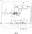
- a system according to the invention can comprise a draining point 30.
- This draining point 30 can be used to discard part of the monophasic fluid 2 or of the liquid phase after its entry in the expandable cell 20 or the expansion cell 40.
- This draining point 30 can be coupled with at least one three-way valve 21, said at least one three-way valve 21 being connected to the draining point and positioned right after ( figure 2 ) and/or right before ( figure 3 ) the expandable cell 20.
- the system can also comprise an observation cell 31.
- Such an observation cell 31 can be positioned between the expandable cell 20 and the high-pressure expansion cell 40. It can be for example positioned after ( figure 2 ) or before ( figure 4 ) the draining points, but it has to be separated from the expandable cell with a valve.
- the observation cell 31 is preferably a sapphire cell but it can also be selected from: borosilicate window or diamond cell.
- the system can also comprise several pressure gauges such as thermal conductivity gauge, Pirani gauge, Penning gauge or ion gauge which are fitted onto the line for monitoring the pressure in vacuum systems.
- pressure gauges such as thermal conductivity gauge, Pirani gauge, Penning gauge or ion gauge which are fitted onto the line for monitoring the pressure in vacuum systems.
- the system can also comprise several valves.
- the subsampling system 1 can comprise a further a three-way valve 21, said three-way valve being positioned between the second valve 41 and the high-pressure expansion cell 40.
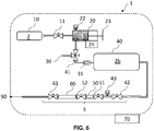
- a subsampling system can comprise a low-pressure section 3.
- Such low-pressure section 3 can for example be arranged to allow the gas pressure to reach a target pressure, preferably said target pressure being selected from 1 to 10 bars.
- the system according to the invention comprises subsampling cells 50, 60.
- the low-pressure section can also comprise a dedicated pressure gauge 43.
- system 1 can comprise at least one, preferably two, subsampling cells 50, 60 arranged so as to collect at least part of the gaseous subsample at a pressure comprised between 1 bar and 10 bars.
- the subsampling cells 50, 60 can also be removably fixed to the subsampling system 1. Hence the subsampling cells 50, 60 are arranged so as to be dissociated from subsampling system 1 and to be transportable.
- the system according to the invention can be installed at the site of sampling of the monophasic fluid 2 and the subsampling cells are transported as such to extraction / purification line connected to a spectrometer.
- the system according to the invention can be installed in a laboratory and the system can be automated to directly inject the subsample in the extraction / purification line connected to a spectrometer.
- the system 1 can comprise a reservoir tank which allows subsample aliquots to be easily stored into the system.
- the previously 'prepared' gases stored in the tank can be used for analyses by automated operation in the system. Therefore, those 'stored' gases make it possible to run overnight measurements automatically.
- the purification line can comprise purification means such as Ti-sponge furnace or Getter pump or cadmium acetate microporous media or silver wool porous media or zeolites or SAES GP 50 or active charcoal.
- purification means can be of particular interest when the monophasic fluid can comprise H 2 S to be removed before storage.
- analytical means for noble gas analysis such as mass-spectrometer can also comprise purification line.
- the system may also comprise at least one turbo pump 90 configured to allow subsampling under high vacuum conditions.
- the invention relates to a subsampling method 100 of a monophasic fluid 2.
- Such a method allows obtaining a gaseous subsample 2b from a monophasic sample, preferably a liquid sample.
- a method according to the invention can use a system 1 according to the invention. However, it can also use any system comprising a first inlet valve 11, an expandable cell 20, a second valve 41, and an expansion cell 40.
- the system used by a method according to the invention can comprise an expandable cell 20 being connected though a three-way valve 21 to an expansion cell 40 and a draining point 30, the first inlet valve 11 being arranged so as to receive the monophasic fluid 2 from a sampling bottle 10; and said expandable cell 20 being thermoregulated and equipped with a pressure gauge 22, said expansion cell 40 being arranged to receive the subsample for the noble gas analysis.
- a method according to the invention will preferably comprise phase split step that will make the initial monophasic fluid 2 turn into a diphasic fluid under equilibrium and an expansion step that will allow the gas pressure of the gaseous subsample to reach the target pressure (e.g., 1-10 bars).
- the target pressure e.g. 1-10 bars
- the subsampling method 100 comprise the step of connecting 120 a monophasic fluid source to the subsampling system 1, Operating 130 the first inlet valve 11; Expanding 140 the expandable cell 20 to obtain a diphasic fluid; Transferring 150 at least a part of the gas phase from the expandable cell 20 to the high-pressure expansion cell 40; and Sampling 160 the gas phase comprised in the high-pressure expansion cell 40 to obtain the gaseous subsample 2b.
- a method according to the invention can comprise a step of preparing 110 the system to the subsampling, a step of reducing 170 the pressure of the gaseous subsample and a step of purifying 180 the gaseous subsample.
- a first step can relate to preparing 110 the system to the subsampling.
- the method is particularly suited for noble gas sampling and the main source of noble gas is the air. Indeed, with the exception of helium the noble gases are many orders of magnitude lower in liquid samples than in air. Hence, the subsampling process must avoid any dead volume (not pumped) and reach a secondary vacuum (10 -7 - 10 -5 mbar under pumping).
- the system and in particular the low-pressure section should be pumped. During flushing, temperature and electrical conductivity should be checked to see if the values stabilize.
- the method according to the invention is particularly advantageous for samples taken in from extreme environment such as downhole samples.
- the monophasic fluid 2 has preferably a pressure range from 100 to 1000 bars.
- a step relates to connecting 120 a monophasic fluid source to the subsampling system 1. Such a connection is preferably made so that the first inlet valve 11 of said subsampling system 1 receives the monophasic fluid 2 and control monophasic fluid 2 flow to the expandable cell 20.
- the monophasic fluid source can be a bottle specifically dedicated to high-pressure collection or any other means adapted for monophasic sample collection from extreme conditions.
- the method also comprises a step of operating 130 the first inlet valve 11 so that the expandable cell 20 receives, through the first inlet valve 11, at least a part of the monophasic fluid 2.
- Operating the first inlet valve 11 can be automatic or manual.
- the transfer of the monophasic fluid 2 from the monophasic fluid source 10 to the expandable cell 20 is an isobar transfer. More preferably, transfer is done so as the pressure in the monophasic fluid source vary of less than 5 percent, preferably less than 1 percent.
- the first inlet valve 11 will be open in order to transfer a small aliquot of the monophasic fluid 2 into the expandable cell 20.
- the operating step will allow a transfer of the monophasic fluid 2 from the monophasic fluid source 10 to the expandable cell 20, said transfer corresponding for example to 1 cc.
- a higher volume of the monophasic fluid 2 can be transfer from the monophasic fluid source 10 to the expandable cell 20, such as more that 1cc, more than 2 cc or more than 5 cc.
- the monophasic fluid source such as a PVT bottle
- the monophasic fluid source can be controlled in pressure and temperature.
- the method also comprises a step of expanding 140 the expandable cell 20 .
- it refers to the expansion of the inner volume of the expandable cell 20.
- the expansion is done preferably at a known pressure, volume and temperature.
- the pressure of the monophasic fluid 2 is preferably decreased at a controlled rate until a bubble point is reached.
- the monophasic fluid 2 is transformed into a diphasic fluid 2a, said diphasic fluid 2a comprising a gas phase and a liquid phase.
- the method of the invention will preferably comprise a monitoring of how gas evolves from oil when pressure falls below the bubble point, this method is comparable to CCE (Constant Composition Expansion), also called CME (Constant Mass Expansion).
- CCE Constant Composition Expansion
- CME Constant Mass Expansion
- the expansion of the expandable cell 20 is preferably done at a rate slower than 0.5 cc per minute.
- the monophasic fluid 2 will be able to support another round of expansion in order to reach it bubble point.
- the method according to the invention comprises the recording of pressure, temperature and volume values in order to perform a pressure-volume curve (PV curve).
- PV curve pressure-volume curve
- the method also comprises a step of operating 150 the second valve 41.
- Said second valve 41 controlling the gas phase flow to the expansion cell 40, so as to transfer only the gas phase from the expandable cell 20 to the expansion cell 40, preferably the high-pressure expansion cell 40.
- the method comprises a sampling 160 of the gas phase comprised in the expansion cell 40 to obtain the gaseous subsample 2b.
- a step of sampling at least a part of the gas phase.
- the gaseous subsample 2b will be suitable for chemical analysis and in particular for a noble gas analysis.
- the method according to the invention also preferably comprises a step of maintaining a constant temperature for the whole subsampling system.
- a maintained constant temperature is preferably over 40°C, more preferably over 50°C.
- a downhole sample collected at a pressure range from 100 to 1000 bars is selected as a monophasic sample. Subsampling of such a high-pressure sample is not an easy task.
- the samples will be at low pressure (1-10 bar) and will be highly fractionated thought the temperature and pression variation from the downhole to the well head.
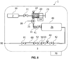
- valves 11 should be closed, and valves 21, 42, 51, 52and 61 opened, (Valve 21 is opened to connect volumes 20 to 40, but is closed to the draining point).
- a turbomolecular pumping system is connected to the valve 61 and the whole system is pumped under high vacuum.
- the expandable cell 20 is adjusted to its minimum volume. Once the whole system under high vacuum, the valve 21 is closed.
- the valve 11 is open in order to transfer an aliquot of the monophasic fluid source to the expandable cell 20.
- a 1 cc capillary can be maintained at reservoir pressure and reservoir temperature between the PVT bottle and the expandable cell 20.
- the 1cc capillary is filled with the monophasic fluid 2 and then isolated from the PVT bottle to avoid any risk of damaging the fluid integrity.
- the expandable cell 20 volume is adjusted gradually to the bubble point of the monophasic fluid 2.
- the fluid is expanded into the syringe volume.
- a PV curve is advantageously performed to characterize it.
- the syringe volume is increased to up to its maximum (e.g. 30cc).
- the pressure can be below the bubble point pressure meaning the fluid became diphasic.
- valves 11 and/or 21 can be opened while access to the monophasic fluid source is closed.
- the expandable cell 20 is retracted while the expanded monophasic fluid 2 is removed.
- the expanded monophasic fluid 2 is introduced in the expandable cell 20 and the expandable 20 volume is adjusted gradually to the bubble point of the monophasic fluid 2.
- valve 21 is open to the sapphire cell.
- the fluid phase is checked through the sapphire cell.
- Valve 41 is open and only gas was transferred to the expansion cell 40.
- valve 41 is closed.
- the gas phase from the monophasic fluid 2 is allowed to expand the sample into the expansion cell.
- the valve 41 is closed to isolate the gas phase, then while the valve 51 is closed, the valve 42 is opened to have a lecture of the pressure into the expansion cell 40.
- Composition of the gas can then be measured for example on a noble gas mass spectrometer.
- composition of the noble gas in the monophasic fluid 2 is back calculated based on the bubble conditions of the fluid, for example based on a calculated PV curve.
- the solution developed by the inventors allow, through a phase split under controlled conditions and an expansion phase, reaching a pressure compatible with spectrometer to identify the initial content of the initial monophasic fluid 2, in particular in noble gas.
Landscapes
- Life Sciences & Earth Sciences (AREA)
- Health & Medical Sciences (AREA)
- General Physics & Mathematics (AREA)
- Immunology (AREA)
- Chemical & Material Sciences (AREA)
- Analytical Chemistry (AREA)
- Biochemistry (AREA)
- General Health & Medical Sciences (AREA)
- Pathology (AREA)
- Physics & Mathematics (AREA)
- Hydrology & Water Resources (AREA)
- Engineering & Computer Science (AREA)
- Biomedical Technology (AREA)
- Molecular Biology (AREA)
- Soil Sciences (AREA)
- Sampling And Sample Adjustment (AREA)
- Other Investigation Or Analysis Of Materials By Electrical Means (AREA)
- Investigating Or Analysing Materials By Optical Means (AREA)
Priority Applications (8)
| Application Number | Priority Date | Filing Date | Title |
|---|---|---|---|
| EP20306665.9A EP4019929A1 (fr) | 2020-12-22 | 2020-12-22 | Système et procédé de sous-échantillonnage d'un sous-échantillon gazeux d'un fluide monophasique pour une analyse de gaz rare |
| US18/268,668 US20250231089A1 (en) | 2020-12-22 | 2021-12-21 | System and method for subsampling a gaseous subsample from a monophasic fluid for noble gas analysis |
| PCT/EP2021/087166 WO2022136478A1 (fr) | 2020-12-22 | 2021-12-21 | Système et procédé de sous-échantillonnage d'un sous-échantillon gazeux à partir d'un fluide monophasique pour analyse de gaz noble |
| EP21840052.1A EP4267933B1 (fr) | 2020-12-22 | 2021-12-21 | Système et procédé de sous-échantillonnage d'un sous-échantillon gazeux d'un fluide monophasique pour une analyse de gaz rare |
| MX2023007416A MX2023007416A (es) | 2020-12-22 | 2021-12-21 | Sistema y procedimiento de submuestreo de una submuestra gaseosa a partir de un fluido monofasico para el analisis de gases nobles. |
| AU2021405505A AU2021405505B2 (en) | 2020-12-22 | 2021-12-21 | System and method for subsampling a gaseous subsample from a monophasic fluid for noble gas analysis |
| CA3197641A CA3197641A1 (fr) | 2020-12-22 | 2021-12-21 | Systeme et procede de sous-echantillonnage d'un sous-echantillon gazeux a partir d'un fluide monophasique pour analyse de gaz noble |
| CONC2023/0007951A CO2023007951A2 (es) | 2020-12-22 | 2023-06-20 | Sistema y procedimiento de submuestreo de una submuestra gaseosa a partir de un fluido monofásico para el análisis de gases nobles |
Applications Claiming Priority (1)
| Application Number | Priority Date | Filing Date | Title |
|---|---|---|---|
| EP20306665.9A EP4019929A1 (fr) | 2020-12-22 | 2020-12-22 | Système et procédé de sous-échantillonnage d'un sous-échantillon gazeux d'un fluide monophasique pour une analyse de gaz rare |
Publications (1)
| Publication Number | Publication Date |
|---|---|
| EP4019929A1 true EP4019929A1 (fr) | 2022-06-29 |
Family
ID=74191497
Family Applications (2)
| Application Number | Title | Priority Date | Filing Date |
|---|---|---|---|
| EP20306665.9A Withdrawn EP4019929A1 (fr) | 2020-12-22 | 2020-12-22 | Système et procédé de sous-échantillonnage d'un sous-échantillon gazeux d'un fluide monophasique pour une analyse de gaz rare |
| EP21840052.1A Active EP4267933B1 (fr) | 2020-12-22 | 2021-12-21 | Système et procédé de sous-échantillonnage d'un sous-échantillon gazeux d'un fluide monophasique pour une analyse de gaz rare |
Family Applications After (1)
| Application Number | Title | Priority Date | Filing Date |
|---|---|---|---|
| EP21840052.1A Active EP4267933B1 (fr) | 2020-12-22 | 2021-12-21 | Système et procédé de sous-échantillonnage d'un sous-échantillon gazeux d'un fluide monophasique pour une analyse de gaz rare |
Country Status (7)
| Country | Link |
|---|---|
| US (1) | US20250231089A1 (fr) |
| EP (2) | EP4019929A1 (fr) |
| AU (1) | AU2021405505B2 (fr) |
| CA (1) | CA3197641A1 (fr) |
| CO (1) | CO2023007951A2 (fr) |
| MX (1) | MX2023007416A (fr) |
| WO (1) | WO2022136478A1 (fr) |
Citations (5)
| Publication number | Priority date | Publication date | Assignee | Title |
|---|---|---|---|---|
| EP0473472A1 (fr) * | 1990-08-28 | 1992-03-04 | Institut Français du Pétrole | Dispositif pour faire des mesures thermodynamiques sur des échantillons de substances provenant notamment de zones pétrolifères |
| GB2276608A (en) * | 1993-03-18 | 1994-10-05 | Atomic Energy Authority Uk | Fluid sampler |
| GB2278830A (en) * | 1993-06-11 | 1994-12-14 | Inst Francais Du Petrole | System for transferring samples under pressure |
| WO2013148442A1 (fr) | 2012-03-28 | 2013-10-03 | Exxonmobil Upstream Research Company | Procédé de détermination du volume d'un gisement souterrain d'hydrocarbures avant forage |
| WO2015078972A1 (fr) * | 2013-11-29 | 2015-06-04 | Gaztransport Et Technigaz | Surveillance d'une cuve etanche et thermiquement isolante |
-
2020
- 2020-12-22 EP EP20306665.9A patent/EP4019929A1/fr not_active Withdrawn
-
2021
- 2021-12-21 WO PCT/EP2021/087166 patent/WO2022136478A1/fr not_active Ceased
- 2021-12-21 CA CA3197641A patent/CA3197641A1/fr active Pending
- 2021-12-21 EP EP21840052.1A patent/EP4267933B1/fr active Active
- 2021-12-21 AU AU2021405505A patent/AU2021405505B2/en active Active
- 2021-12-21 US US18/268,668 patent/US20250231089A1/en active Pending
- 2021-12-21 MX MX2023007416A patent/MX2023007416A/es unknown
-
2023
- 2023-06-20 CO CONC2023/0007951A patent/CO2023007951A2/es unknown
Patent Citations (5)
| Publication number | Priority date | Publication date | Assignee | Title |
|---|---|---|---|---|
| EP0473472A1 (fr) * | 1990-08-28 | 1992-03-04 | Institut Français du Pétrole | Dispositif pour faire des mesures thermodynamiques sur des échantillons de substances provenant notamment de zones pétrolifères |
| GB2276608A (en) * | 1993-03-18 | 1994-10-05 | Atomic Energy Authority Uk | Fluid sampler |
| GB2278830A (en) * | 1993-06-11 | 1994-12-14 | Inst Francais Du Petrole | System for transferring samples under pressure |
| WO2013148442A1 (fr) | 2012-03-28 | 2013-10-03 | Exxonmobil Upstream Research Company | Procédé de détermination du volume d'un gisement souterrain d'hydrocarbures avant forage |
| WO2015078972A1 (fr) * | 2013-11-29 | 2015-06-04 | Gaztransport Et Technigaz | Surveillance d'une cuve etanche et thermiquement isolante |
Non-Patent Citations (6)
| Title |
|---|
| BARRY ET AL.: "Noble gases in deep-water oils of the U.S. Gulf of Mexico", GEOCHEM. GEOPHYS. GEOSYST., vol. 19, no. 11, 2018, pages 4218 - 4235 |
| BARRY ET AL.: "Tracing enhanced oil recovery signatures in casing gases using noble gases", EARTH PLANET. SCI. LETT., vol. 496, 2018, pages 57 - 67 |
| DANESH, A: "PVT and phase behaviour of petroleum reservoir fluids", 1998, ELSEVIER |
| HEIDELBERGBALLENTINE ET AL.: "A Magnus opus: Helium, neon, and argon isotopes in a North Sea oilfield", GEOCHIMICA ET COSMOCHIMICA ACTA, vol. 60, no. 5, 1996, pages 831 - 849 |
| HOLLANDGILFILLAN: "The noble gases as geochemical tracers", 2013, SPRINGER, article "Application of noble gases to the viability of C02 storage", pages: 177 - 223 |
| TYNE ET AL.: "AGU Fall Meeting", 2019, AGU, article "Tracing the Fate of Injected CO2 using Noble Gas Isotopes" |
Also Published As
| Publication number | Publication date |
|---|---|
| EP4267933A1 (fr) | 2023-11-01 |
| CO2023007951A2 (es) | 2023-06-30 |
| WO2022136478A1 (fr) | 2022-06-30 |
| CA3197641A1 (fr) | 2022-06-30 |
| MX2023007416A (es) | 2023-06-29 |
| US20250231089A1 (en) | 2025-07-17 |
| EP4267933B1 (fr) | 2025-04-23 |
| AU2021405505A1 (en) | 2023-06-15 |
| AU2021405505B2 (en) | 2025-05-15 |
Similar Documents
| Publication | Publication Date | Title |
|---|---|---|
| Zhang et al. | Using noble gases to trace groundwater evolution and assess helium accumulation in Weihe Basin, central China | |
| Holland et al. | Application of noble gases to the viability of CO2 storage | |
| Gardner et al. | An advanced passive diffusion sampler for the determination of dissolved gas concentrations | |
| Humez et al. | An 8-year record of gas geochemistry and isotopic composition of methane during baseline sampling at a groundwater observation well in Alberta (Canada) | |
| Warr et al. | Determining noble gas partitioning within a CO2–H2O system at elevated temperatures and pressures | |
| Van Hemert et al. | Adsorption of carbon dioxide and a hydrogen-carbon dioxide mixture | |
| US10995612B2 (en) | Method for exploitation and/or monitoring of an aquifer comprising at least one dissolved gas | |
| Visser et al. | A membrane inlet mass spectrometry system for noble gases at natural abundances in gas and water samples | |
| CN105092687A (zh) | 一种稀有气体全组分含量在线分析方法 | |
| JP2023551850A (ja) | 炭化水素貯留層における炭化水素と水との接触位置を決定するための装置及び方法 | |
| Hendry et al. | Sources of radiogenic helium in a clay till aquitard and its use to evaluate the timing of geologic events | |
| CN105628575A (zh) | 页岩性质测定方法、装置和页岩性质测定仪 | |
| EP4267933B1 (fr) | Système et procédé de sous-échantillonnage d'un sous-échantillon gazeux d'un fluide monophasique pour une analyse de gaz rare | |
| US11852616B2 (en) | High pressure high temperature direct fluid injection to gas chromatography in a PVT system | |
| Lv et al. | Distribution and enrichment mechanism of helium in the Hetianhe gas field, Tarim basin, northwest China | |
| Likholyot et al. | Experimental and theoretical study of hydration of halide ions | |
| Matsumoto et al. | A portable membrane contactor sampler for analysis of noble gases in groundwater | |
| Li | Tracing fluid dynamics with noble gas and stable isotope systematics: examples from Krafla, Iceland and Sichuan Basin, China | |
| CN118471358A (zh) | 一种兼顾了孔隙度和生氦“年龄”校正的原位氦气资源量评价方法 | |
| Myers et al. | The impact of partition coefficient data on the interpretation of chemical tracer behaviour in carbon geosequestration projects | |
| US12429473B1 (en) | Systems and methods for evaluating hydrogen generation potential from rocks in natural and enhanced hydrogen production systems using gas properties | |
| US20260118339A1 (en) | Systems and methods for evaluating hydrogen generation potential from rocks in natural and enhanced hydrogen production systems using gas properties | |
| Nowak et al. | High-resolution stable carbon isotope monitoring indicates variable flow dynamic patterns in a deep saline aquifer at the Ketzin pilot site (Germany) | |
| Zhong | Using noble gases to trace subsurface fluid dynamics and helium accumulation in the Sichuan Basin, the Ordos Basin and the Qinshui Basin, China | |
| US20260118340A1 (en) | Systems and methods for evaluating hydrogen generation potential from rocks in geologic hydrogen production systems using gas properties |
Legal Events
| Date | Code | Title | Description |
|---|---|---|---|
| PUAI | Public reference made under article 153(3) epc to a published international application that has entered the european phase |
Free format text: ORIGINAL CODE: 0009012 |
|
| STAA | Information on the status of an ep patent application or granted ep patent |
Free format text: STATUS: THE APPLICATION HAS BEEN PUBLISHED |
|
| AK | Designated contracting states |
Kind code of ref document: A1 Designated state(s): AL AT BE BG CH CY CZ DE DK EE ES FI FR GB GR HR HU IE IS IT LI LT LU LV MC MK MT NL NO PL PT RO RS SE SI SK SM TR |
|
| RAP1 | Party data changed (applicant data changed or rights of an application transferred) |
Owner name: TOTALENERGIES ONETECH |
|
| STAA | Information on the status of an ep patent application or granted ep patent |
Free format text: STATUS: THE APPLICATION IS DEEMED TO BE WITHDRAWN |
|
| 18D | Application deemed to be withdrawn |
Effective date: 20230103 |