EP4019943B1 - Fotoakustische detektionsvorrichtung mit einer schutzmembran - Google Patents
Fotoakustische detektionsvorrichtung mit einer schutzmembran Download PDFInfo
- Publication number
- EP4019943B1 EP4019943B1 EP21217206.8A EP21217206A EP4019943B1 EP 4019943 B1 EP4019943 B1 EP 4019943B1 EP 21217206 A EP21217206 A EP 21217206A EP 4019943 B1 EP4019943 B1 EP 4019943B1
- Authority
- EP
- European Patent Office
- Prior art keywords
- membrane
- cavity
- face
- contact
- aperture
- Prior art date
- Legal status (The legal status is an assumption and is not a legal conclusion. Google has not performed a legal analysis and makes no representation as to the accuracy of the status listed.)
- Active
Links
Images

Classifications
-
- G—PHYSICS
- G01—MEASURING; TESTING
- G01N—INVESTIGATING OR ANALYSING MATERIALS BY DETERMINING THEIR CHEMICAL OR PHYSICAL PROPERTIES
- G01N21/00—Investigating or analysing materials by the use of optical means, i.e. using sub-millimetre waves, infrared, visible or ultraviolet light
- G01N21/17—Systems in which incident light is modified in accordance with the properties of the material investigated
- G01N21/1702—Systems in which incident light is modified in accordance with the properties of the material investigated with opto-acoustic detection, e.g. for gases or analysing solids
-
- G—PHYSICS
- G01—MEASURING; TESTING
- G01N—INVESTIGATING OR ANALYSING MATERIALS BY DETERMINING THEIR CHEMICAL OR PHYSICAL PROPERTIES
- G01N21/00—Investigating or analysing materials by the use of optical means, i.e. using sub-millimetre waves, infrared, visible or ultraviolet light
- G01N21/01—Arrangements or apparatus for facilitating the optical investigation
- G01N21/03—Cuvette constructions
-
- G—PHYSICS
- G01—MEASURING; TESTING
- G01N—INVESTIGATING OR ANALYSING MATERIALS BY DETERMINING THEIR CHEMICAL OR PHYSICAL PROPERTIES
- G01N21/00—Investigating or analysing materials by the use of optical means, i.e. using sub-millimetre waves, infrared, visible or ultraviolet light
- G01N21/01—Arrangements or apparatus for facilitating the optical investigation
- G01N21/03—Cuvette constructions
- G01N21/0303—Optical path conditioning in cuvettes, e.g. windows; adapted optical elements or systems; path modifying or adjustment
-
- G—PHYSICS
- G01—MEASURING; TESTING
- G01N—INVESTIGATING OR ANALYSING MATERIALS BY DETERMINING THEIR CHEMICAL OR PHYSICAL PROPERTIES
- G01N21/00—Investigating or analysing materials by the use of optical means, i.e. using sub-millimetre waves, infrared, visible or ultraviolet light
- G01N21/01—Arrangements or apparatus for facilitating the optical investigation
- G01N21/15—Preventing contamination of the components of the optical system or obstruction of the light path
-
- G—PHYSICS
- G01—MEASURING; TESTING
- G01N—INVESTIGATING OR ANALYSING MATERIALS BY DETERMINING THEIR CHEMICAL OR PHYSICAL PROPERTIES
- G01N29/00—Investigating or analysing materials by the use of ultrasonic, sonic or infrasonic waves; Visualisation of the interior of objects by transmitting ultrasonic or sonic waves through the object
- G01N29/22—Details, e.g. general constructional or apparatus details
- G01N29/24—Probes
- G01N29/2418—Probes using optoacoustic interaction with the material, e.g. laser radiation, photoacoustics
-
- G—PHYSICS
- G01—MEASURING; TESTING
- G01N—INVESTIGATING OR ANALYSING MATERIALS BY DETERMINING THEIR CHEMICAL OR PHYSICAL PROPERTIES
- G01N33/00—Investigating or analysing materials by specific methods not covered by groups G01N1/00 - G01N31/00
- G01N33/48—Biological material, e.g. blood, urine; Haemocytometers
- G01N33/483—Physical analysis of biological material
- G01N33/487—Physical analysis of biological material of liquid biological material
-
- G—PHYSICS
- G01—MEASURING; TESTING
- G01N—INVESTIGATING OR ANALYSING MATERIALS BY DETERMINING THEIR CHEMICAL OR PHYSICAL PROPERTIES
- G01N21/00—Investigating or analysing materials by the use of optical means, i.e. using sub-millimetre waves, infrared, visible or ultraviolet light
- G01N21/01—Arrangements or apparatus for facilitating the optical investigation
- G01N21/03—Cuvette constructions
- G01N2021/0385—Diffusing membrane; Semipermeable membrane
-
- G—PHYSICS
- G01—MEASURING; TESTING
- G01N—INVESTIGATING OR ANALYSING MATERIALS BY DETERMINING THEIR CHEMICAL OR PHYSICAL PROPERTIES
- G01N21/00—Investigating or analysing materials by the use of optical means, i.e. using sub-millimetre waves, infrared, visible or ultraviolet light
- G01N21/17—Systems in which incident light is modified in accordance with the properties of the material investigated
- G01N21/1702—Systems in which incident light is modified in accordance with the properties of the material investigated with opto-acoustic detection, e.g. for gases or analysing solids
- G01N2021/1706—Systems in which incident light is modified in accordance with the properties of the material investigated with opto-acoustic detection, e.g. for gases or analysing solids in solids
-
- G—PHYSICS
- G01—MEASURING; TESTING
- G01N—INVESTIGATING OR ANALYSING MATERIALS BY DETERMINING THEIR CHEMICAL OR PHYSICAL PROPERTIES
- G01N2201/00—Features of devices classified in G01N21/00
- G01N2201/06—Illumination; Optics
- G01N2201/061—Sources
- G01N2201/06113—Coherent sources; lasers
Definitions
- the technical field of the invention is the detection of an analyte by photoacoustic detection.
- Photoacoustic detection is based on the detection of an acoustic wave generated under the effect of the absorption, by an analyzed medium, of an impulsive or amplitude modulated incident electromagnetic wave.
- the acoustic wave is formed following a heating of molecules of interest, present in the analyzed medium, under the effect of the absorption of the incident wave.
- the heating causes a modulated thermal expansion of the medium, the latter being the origin of the acoustic wave.
- Photoacoustic sensing can be specific to a particular analyte, by adjusting the wavelength of the incident electromagnetic wave to an absorption wavelength of the analyte. Photoacoustic detection has thus been applied to detect gaseous species in a gas, or to detect the presence of particular molecules in biological tissues. The wavelength of the incident wave is frequently in the infrared.
- Photoacoustic detection then constitutes a non-invasive analysis technique, which can be implemented in scattering or opaque media.
- an amplitude modulated laser light source is used, activated at a frequency of between several tens of Hz and several tens of kHz.
- the objective is to estimate a concentration of glucose in the bodily interstitial fluid, at a depth between 10 ⁇ m and 100 ⁇ m below the surface of a user's skin.
- a photoacoustic detection device placed against the skin of a user is used.
- a photoacoustic detection device comprises a transducer, configured to detect an acoustic wave modulated in amplitude under the effect of the periodic heating induced by the modulated light wave. More precisely, the photoacoustic detection device is arranged to detect a periodic pressure modulation, according to a period depending on the modulation frequency of the light wave. A response function of the photoacoustic device can be calibrated, so as to establish a correlation between the pressure modulation measured and the quantity of analyte present in the analyzed medium.
- the document US2014/073899 describes a photoacoustic detection device comprising a cavity intended to be applied against the body of a user.
- the cavity is filled with a coupling agent impregnating a sponge, which allows optical index matching between a light source and the body of the user. It also allows acoustic impedance matching between the user's body and an acoustic transducer.
- a coupling gel extending between the skin of a user and an acoustic transducer, is also described in US2005/090725 .
- Difficulty may arise due to water vapor emanating from the skin, due to the sweat effect. Water vapor can condense and form droplets, which can damage the transducer. Furthermore, during use of the device, dust or other undesirable elements, for example skin debris, can accumulate in the device.
- the object of the invention is to solve this problem.
- through opening is meant an opening allowing air to pass through the opening, between the lower face and the upper face of the membrane.
- the membrane may be solid in the intersection portion. By full, it is understood without through opening.
- the transparent material may consist of at least one material chosen from: Si, Ge, AlN, ZnSe, BaF 2 , CaF 2 , KBr, ZnS, Sapphire.
- the upper face of the membrane may include an anti-reflection coating.
- the antireflection coating can be applied over the entire upper face, and optionally over all or part of the lower face.
- the membrane is monolithic. It is made from the same material (excluding any hydrophobic coating or anti-reflective coating).
- the transverse wall may be parallel to the contact face.
- the membrane is removably placed in the cavity.
- the light source can be a laser source.
- the volume of the cavity can be less than 50 ⁇ L.
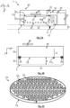
- the device 1 is configured to be applied against a medium 2 to be analyzed.
- the device comprises a contact face 3, intended to be applied against the medium to be analyzed.
- the mating face is designed to conform to the medium against which it is intended to bear. It is for example flat.
- medium 2 is a user's skin.
- the device comprises a light source 10, configured to emit a light beam 11 propagating as far as the medium 2 to be analyzed.
- the light source 10 is pulsed or amplitude modulated.
- the light beam 11 is emitted in an emission spectral band ⁇ comprising an absorption wavelength ⁇ a of an analyte 4 present in the medium.
- One objective of the device 1 is to detect the presence of the analyte 4 and possibly to estimate its concentration.
- Analyte 4 can be a molecule present in a bodily fluid. It may for example be glucose, or a bodily analyte of cholesterol, triglyceride, urea, albumin, alcohol (for example ethanol), tetrahydrocannabinol type.
- the spectral emission band preferably extends in the visible or in the infrared, for example between wavelengths of 3 ⁇ m and 15 ⁇ m.
- the emission spectral band ⁇ is sufficiently narrow, so that the device 1 is specific to a single analyte.
- the spectral band of emission is centered on a glucose absorption wavelength, for example corresponding to a wave number of 1034 cm -1 .
- the light source 10 may in particular be a pulsed laser source, for example a wavelength-tunable laser of the QCL (Quantum Cascade Laser) type.
- the spectral emission band ⁇ is then located in the infrared.
- the light source can be a filament-type source, or a light-emitting diode. According to these embodiments, it is preferable to combine the light source with a band-pass filter to define a sufficiently narrow emission spectral band, and centered on the absorption wavelength considered. However, the use of a laser source is preferred.
- the device 1 comprises an optical component 15, configured to deflect the light beam 11 emitted by the light source, towards the medium 2 to be analyzed.
- the device 1 is intended to be applied against the medium to be analyzed 2. It comprises a confinement envelope 21, placed in contact with the medium, and delimiting a cavity 20.
- the cavity 20 leads to a contact opening 22, made in the face of the contact 3, so as to emerge on the medium 2.
- the device comprises a transparent window 17, configured to transmit the incident light beam 11.
- the optical component 15 is a reflector, taking the form of a reflecting prism.
- the incident light beam 11 reaches the medium 2 at normal or substantially normal incidence.
- substantially normal normal is meant considering an angular tolerance of ⁇ 30°.
- an acoustic wave called photoacoustic wave 12
- the photoacoustic wave 12 is an acoustic wave formed from periodic heating of the medium by the incident light beam 11, the latter being pulsed or amplitude modulated.
- a portion of the photoacoustic wave 12 extends through the cavity 20 so as to be detected by an acoustic transducer 28.
- the acoustic transducer 28 is connected to the cavity 20 by an acoustic channel 25.
- the acoustic transducer may be a microphone , having a detection spectral range comprising the frequency of the photoacoustic wave.
- the photoacoustic wave is modulated in amplitude depending on the pulse or amplitude modulation frequency of the light source. Thus, at the level of the transducer, the pressure is modulated in amplitude.
- substantially parallel is meant parallel assuming an angular tolerance of ⁇ 30° or ⁇ 20°.
- the lateral face 21 1 extends between the contact face 3 and the transverse face 21 2 .
- the device includes a protective cover 30, enveloping the previously described components.
- the light source is arranged on a support 13, connected to the cover 30.
- the modulation amplitude of the photoacoustic wave A , detected by the acoustic transducer is proportional to the absorption coefficient of the medium ⁇ ( ⁇ ).
- the latter is considered to be proportional to the concentration of analyte in the medium.
- the measurement of the modulation amplitude A by the acoustic transducer 28 allows an estimation of the concentration of analyte 4 in the medium, by taking into account the absorption coefficient of the medium ⁇ ( ⁇ ).
- the membrane forms a protective screen, interposed between the lower cavity 20 i and the upper cavity 20 s .
- This makes it possible to isolate the upper cavity 20 s from droplets of water or dust, or other undesirable elements likely to be present in the lower cavity 20 i , by having accessed the latter through the contact opening 22.
- the membrane 23 extends inside the cavity 20, at a non-zero distance d from the contact opening 22. Indeed, during the implementation of the device, it is preferable that the membrane 23 is not not in contact with the skin 2, so as not to disturb the heating of a superficial layer of gas in contact with the skin 2.
- the fact of arranging the membrane at a distance makes it possible to maintain a layer of air between the opening contact 22 and the membrane.
- the distance between the membrane and the contact opening is preferably greater than 200 ⁇ m, or 500 ⁇ m.
- the membrane preferably extends across the entire cavity, opposite the contact face 3. It extends between opposite points of the lateral face.
- the membrane is preferably arranged parallel to the contact face, or substantially parallel to the latter.
- the membrane 23 is maintained inside the cavity 20, by a support 24.
- the membrane is inserted into the support 24.
- the membrane 23 can be removable, which allows replacement and/or cleaning of the latter.
- the light beam 11 crosses the membrane 23 before reaching the contact opening 22.
- the membrane has an intersection portion 23 int , corresponding to the part of the membrane crossed by the beam bright 11.
- the membrane is formed of a material having a high transmittance in the spectral band ⁇ of the emission beam 11.
- high transmittance we mean a transmittance of the material preferably greater than 0 ,4 or even and preferably greater than 0.8, for example of the order of 0.9 or more.
- the material can for example be silicon.
- transmittance is meant a fraction of the light intensity transmitted by the membrane 23.
- the membrane may be partially or entirely formed of Si, or another material transparent to infrared, for example porous Si, Ge, AlN, ZnSe , BaF 2 , CaF 2 , KBr, ZnS, Sapphire.
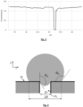
- FIG. 2 represents the transmittance (axis of the ordinates), according to the wavelength (axes of the abscissas - unit ⁇ m), of a Si membrane of thickness 300 ⁇ m.
- the transmittance is affected by the reflections, in particular at the level of the upper face 23 s .
- the transmittance can be increased, to reach values close to 1, by applying an anti-reflection coating, in particular on the upper face 23 s and preferably the upper face 23 s and the lower face 23 i .
- the antireflection coating can take the form of a solid “quarter wave” layer, deposited in the form of a thin layer. The deposition of the thin layer can take place on all or part of the upper face (and preferably of the lower face), without risk of blocking the through openings, due to the low thickness of the thin layer.
- the membrane can also be composite, comprising a material considered to be sufficiently transparent to infrared at the level of the intersection portion 23 int , of another material outside the intersection portion.
- a composite membrane is described below in connection with the figure 5B .
- the membrane comprises through-openings 23 o , extending through the entire thickness of the membrane.
- the through openings are represented on the figure 1C .
- the through openings are sized to transmit the pressure modulation through the membrane 23, while blocking drops of liquid or dust. These through openings 23 allow air communication between the lower cavity 20 i and the upper cavity 20 s .
- Expression (2) comes from Cho, H.-Y. Kim, JY Kang, and TS Kim, "How the capillary burst microvalve works", J. Colloid Interface Sci., vol. 306, no. 2, p. 379-385, February 2007 .
- Expression (2) defines a condition of penetration of the drop into a through opening of circular section. The membrane blocks gout when ⁇ p > 0.
- the drop forms a meniscus, which engages in the through opening 23 o , and is subjected to capillary forces tending to cause the drop to progress inside a capillary formed by the through opening.
- the resulting pressure is ⁇ 2 ⁇ cos ⁇ AT r .
- a residual part of the drop is retained on the lower face 23 i , and is subjected to capillary forces.
- the resulting pressure is 2 ⁇ cos ⁇ R R .
- the wetting angle ⁇ R it is possible to apply a hydrophobic surface treatment to the lower face 23 i of the membrane.
- the material forming the membrane is Si, which is a hydrophilic material
- the wetting angle for water is 5°.
- the wetting angle is of the order of 20° to 40° .
- the application of a hydrophobic surface treatment for example of the silanization type (grafting of hydrophobic silane functions), makes it possible to increase the wetting angle to 110° for the water and 80° for the biological buffer.
- a hydrophobic surface treatment thus reinforces the drop retention capacity on the underside of the membrane.
- the hydrophobic treatment can also "overflow" to the internal surface of the through openings.
- the surface tension ⁇ is also a determining parameter.
- the radius of the through openings is preferably between 5 ⁇ m and 25 ⁇ m, and preferably between 5 ⁇ m and 15 ⁇ m.
- the transmission of the pressure modulations is optimal, but the value ⁇ p decreases: the membrane is less able to block a passage of droplets through the through openings.
- the thickness ⁇ of the membrane 23 is preferably between 100 ⁇ m and 1 mm, and preferably between 150 ⁇ m and 750 ⁇ m.
- each through opening also depends on the thickness ⁇ of the membrane.
- Through-apertures can be formed from an Si substrate by photolithography followed by wet etching. In this case, it is considered that it is possible to form through openings whose diameter is of the order of one tenth of the thickness ⁇ , or even less if necessary.
- the membrane is dimensioned to allow transmission of the pressure modulation between the lower and upper parts of the cavity.
- the number of through openings must be determined so that the effect of the membrane on the photoacoustic wave can be considered negligible, in the frequency range corresponding to the pulse frequency of the light source.
- the opening factor of the membrane corresponds to a ratio between the cumulative surface of each through opening on the total surface of the lower face (or of the upper face).
- the openness factor can be between 0.01 and 0.3.
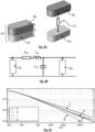
- the inventors have modeled the transmission of the amplitude modulations of the photoacoustic wave 12 for two aperture factors.
- the model was developed by considering that the membrane constitutes an acoustic impedance analogous to an electrical impedance.
- There figure 4A represents the modeled cavity 20 (left figure), the membrane 23, arranged at mid-height, forming an acoustic impedance comparable to an electrical impedance Z (right figure).
- the acoustic impedance was modeled by an RLC circuit as shown in the figure 4B .
- the membrane is likened to a circuit R M , L M , C M , between the lower cavity 20 i and the upper cavity 20 s .
- the thickness of the modeled membrane was 200 ⁇ m.
- Fig. 4C shows the effect of the opening factor on the transmission of the pressure modulation on either side of the membrane. It is observed that the second opening factor, which is lower, leads to an attenuation of the pressure modulation transmitted by the membrane, in particular at high frequencies.
- the intersection portion 23 int of the membrane may be solid, as shown in the figure 5A .
- the solid portion may comprise an antireflection coating, applied to the upper face 23 s and preferably also to the lower face 23 i .
- the anti-reflective coating can be a thin film or a photonic crystal.
- full portion is meant a portion having no through opening.
- the membrane can be monolithic, that is to say formed from the same material, excluding any antireflection treatment or any hydrophobic treatment.
- FIG 5B shows a variant, according to which the membrane is a composite membrane.
- the membrane is composed of a first material 23 1 , standard, not necessarily transparent in the infrared, apart from the intersection portion.
- the membrane comprises an auxiliary material 23 a , transparent in the infrared.
- the first material 23 1 can be that of a standard porous membrane, for example a material of the GoreTex (registered trademark) type.
- the auxiliary material 23 a is different from the first material 23 1 .
Landscapes
- Health & Medical Sciences (AREA)
- Life Sciences & Earth Sciences (AREA)
- Physics & Mathematics (AREA)
- Chemical & Material Sciences (AREA)
- Analytical Chemistry (AREA)
- Biochemistry (AREA)
- General Health & Medical Sciences (AREA)
- General Physics & Mathematics (AREA)
- Immunology (AREA)
- Pathology (AREA)
- Engineering & Computer Science (AREA)
- Biomedical Technology (AREA)
- Molecular Biology (AREA)
- Biophysics (AREA)
- Hematology (AREA)
- Urology & Nephrology (AREA)
- Food Science & Technology (AREA)
- Medicinal Chemistry (AREA)
- Optics & Photonics (AREA)
- Investigating Or Analysing Materials By Optical Means (AREA)
- Measurement Of The Respiration, Hearing Ability, Form, And Blood Characteristics Of Living Organisms (AREA)
- Investigating Or Analyzing Materials By The Use Of Ultrasonic Waves (AREA)
Claims (14)
- Photoakustische Detektionsvorrichtung (1), die dazu bestimmt ist, mit einer Kontaktseite (3) an ein zu analysierendes Milieu (2) angelegt zu werden, wobei die Vorrichtung umfasst:- einen Hohlraum (20), der auf einer Kontaktöffnung (22) mündet, wobei die Kontaktöffnung in der Kontaktseite ausgebildet ist;- eine impulsartige oder amplitudenmodulierte Lichtquelle (10), die dazu ausgestaltet ist, wenn sie aktiviert ist, einen einfallenden Lichtstrahl (11), in einem Emissionsspektralband (Δλ), durch den Hohlraum (20) hindurch bis zu der Kontaktöffnung auszusenden;- einen Schallwandler (28), der mit dem Hohlraum verbunden ist und dazu ausgestaltet ist, eine Schallwelle (12) zu detektieren, die sich durch den Hohlraum hindurch erstreckt;so dass, unter der Wirkung einer Beleuchtung des Milieus durch den einfallenden Lichtstrahl, der Schallwandler eine Schallwelle detektiert, die durch eine Erwärmung des Milieus (2) erzeugt wird;
wobei die Vorrichtung dadurch gekennzeichnet ist, dass:- der Hohlraum eine Membran umfasst, die sich durch den Hohlraum hindurch gegenüber der Kontaktseite erstreckt;- die Membran durch eine Unterseite (23i) und eine Oberseite (23s) begrenzt wird, wobei die Membran durchgehende Öffnungen (23o) umfasst, die zwischen der Unterseite und der Oberseite ausgebildet sind;- die Membran sich im Inneren des Hohlraums erstreckt, in einem Abstand (d) ungleich null von der Kontaktseite (3). - Vorrichtung nach Anspruch 1, wobei der Radius jeder durchgehenden Öffnung (23o) zwischen 5 µm und 25 µm beträgt.
- Vorrichtung nach einem der vorhergehenden Ansprüche, bei der:- die Membran einen Öffnungsfaktor definiert, der einem Verhältnis einer kumulierten Fläche jeder durchgehenden Öffnung zur Gesamtfläche der Unterseite oder der Oberseite der Membran entspricht;- der Öffnungsfaktor zwischen 0,05 und 0,3 beträgt.
- Vorrichtung nach einem der vorhergehenden Ansprüche, bei der die Dicke der Membran zwischen 100 µm und 1 mm beträgt.
- Vorrichtung nach einem der vorhergehenden Ansprüche, bei der:- die Membran so gestaltet ist, dass, wenn die Lichtquelle aktiviert ist, der einfallende Lichtstrahl die Membran durchquert, bevor er die Kontaktöffnung (22) erreicht;- die Membran einen Grenzflächenabschnitt (23int) umfasst, der einem Teil der Membran entspricht, der von dem Lichtstrahl durchquert wird;- mindestens in dem Grenzflächenabschnitt die Membran aus einem transparenten Material besteht, das einen Transmissionsgrad, im Emissionsspektralband, von mehr als 0,4 aufweist.
- Vorrichtung nach Anspruch 5, wobei die Membran in dem Grenzflächenabschnitt durchgehend ist.
- Vorrichtung nach einem der Ansprüche 5 oder 6, bei der das transparente Material aus mindestens einem Material besteht, das gewählt ist unter: Si, Ge, AIN, ZnSe, BaF2, CaF2, KBr, ZnS, Saphir.
- Vorrichtung nach einem der Ansprüche 5 bis 7, bei der mindestens in dem Grenzflächenabschnitt (23int) die Oberseite (23s) der Membran eine Antireflexbeschichtung umfasst.
- Vorrichtung nach einem der Ansprüche 5 bis 8, bei der die Membran aus Folgendem besteht:- einem ersten Material (23i) außerhalb des Grenzflächenabschnitts;- einem Hilfsmaterial (23a), welches das transparente Material bildet, in dem Grenzflächenabschnitt.
- Vorrichtung nach einem der vorhergehenden Ansprüche, bei der die Membran eine hydrophobe Beschichtung auf der Unterseite umfasst.
- Vorrichtung nach einem der vorhergehenden Ansprüche, bei der:- der Hohlraum durch eine Querwand (212) und eine Seitenwand (211) begrenzt wird, wobei sich die Seitenwand zwischen der Querwand und der Kontaktseite erstreckt;- die Membran sich zwischen zwei entgegengesetzten Seiten der Seitenwand erstreckt.
- Vorrichtung nach einem der vorhergehenden Ansprüche, bei der die Membran in dem Hohlraum lösbar angeordnet ist.
- Vorrichtung nach einem der vorhergehenden Ansprüche, bei der die Lichtquelle eine Laserquelle ist.
- Vorrichtung nach einem der vorhergehenden Ansprüche, bei der das Volumen des Hohlraums weniger als 50 µL beträgt.
Applications Claiming Priority (1)
| Application Number | Priority Date | Filing Date | Title |
|---|---|---|---|
| FR2014113A FR3118488B1 (fr) | 2020-12-24 | 2020-12-24 | Dispositif de détection photoacoustique comportant une membrane de protection |
Publications (3)
| Publication Number | Publication Date |
|---|---|
| EP4019943A1 EP4019943A1 (de) | 2022-06-29 |
| EP4019943B1 true EP4019943B1 (de) | 2023-06-07 |
| EP4019943C0 EP4019943C0 (de) | 2023-06-07 |
Family
ID=75339866
Family Applications (1)
| Application Number | Title | Priority Date | Filing Date |
|---|---|---|---|
| EP21217206.8A Active EP4019943B1 (de) | 2020-12-24 | 2021-12-22 | Fotoakustische detektionsvorrichtung mit einer schutzmembran |
Country Status (6)
| Country | Link |
|---|---|
| US (1) | US11774347B2 (de) |
| EP (1) | EP4019943B1 (de) |
| JP (1) | JP7705344B2 (de) |
| KR (1) | KR20220092428A (de) |
| CN (1) | CN114674751A (de) |
| FR (1) | FR3118488B1 (de) |
Families Citing this family (4)
| Publication number | Priority date | Publication date | Assignee | Title |
|---|---|---|---|---|
| FR3129726B1 (fr) * | 2021-11-28 | 2023-10-20 | Commissariat Energie Atomique | Dispositif de détection photoacoustique compact |
| FR3142255B1 (fr) * | 2022-11-18 | 2025-10-24 | Eclypia | dispositif de détection photoacoustique |
| EP4450953B1 (de) * | 2023-04-20 | 2025-10-29 | Eclypia | Photoakustische detektionsvorrichtung |
| FR3164016A1 (fr) * | 2024-06-30 | 2026-01-02 | Commissariat A L' Energie Atomique Et Aux Energies Alternatives | Procédé de fabrication d’une enceinte d’un dispositif de détection photoacoustique |
Family Cites Families (14)
| Publication number | Priority date | Publication date | Assignee | Title |
|---|---|---|---|---|
| US20050090725A1 (en) * | 2003-10-28 | 2005-04-28 | Joseph Page | Disposable couplings for biometric instruments |
| WO2005068973A1 (en) * | 2004-01-13 | 2005-07-28 | Glucon Inc. | Photoacoustic sensor |
| CN100558297C (zh) * | 2008-07-03 | 2009-11-11 | 江西科技师范学院 | 手表式无创光声血糖监测仪 |
| JP5469113B2 (ja) * | 2011-02-24 | 2014-04-09 | 富士フイルム株式会社 | 光音響分析用プローブユニットおよび光音響分析装置 |
| WO2014021335A1 (ja) * | 2012-07-30 | 2014-02-06 | 株式会社三菱ケミカルホールディングス | 検体情報検出ユニット、検体情報処理装置、電動歯ブラシ装置、電動シェーバー装置、検体情報検出装置、老齢化度評価方法、及び老齢化度評価装置 |
| US20140073899A1 (en) * | 2012-09-12 | 2014-03-13 | Nellcor Puritan Bennett LLC. | Photoacoustic sensor system |
| CN103054558A (zh) * | 2013-01-29 | 2013-04-24 | 广州佰奥廷电子科技有限公司 | 一体化手持式的光声显微成像探头 |
| US20150051473A1 (en) * | 2013-08-15 | 2015-02-19 | Covidien Lp | Systems and methods for photoacoustic spectroscopy |
| JP2016049216A (ja) * | 2014-08-29 | 2016-04-11 | プレキシオン株式会社 | 光音響探触子及び光音響画像化装置 |
| JP6689281B2 (ja) * | 2015-09-11 | 2020-04-28 | ギガフォトン株式会社 | 極端紫外光生成装置 |
| US11105738B2 (en) * | 2016-11-28 | 2021-08-31 | Kyocera Corporation | Sensor wiring substrate, sensor package, and sensor device |
| EP3570747A2 (de) * | 2017-01-23 | 2019-11-27 | Roche Diabetes Care GmbH | Implantierbares sensorelement und verfahren zur detektion von mindestens einem analyt in einer körperflüssigkeit |
| DE102017219338B3 (de) | 2017-10-27 | 2019-02-28 | Humboldt-Universität Zu Berlin | Photoakustik-Sensorkopf und Photoakustik-Messapparat mit verbesserter Störsignal-Unterdrückung |
| MX2022005395A (es) * | 2019-11-08 | 2022-05-24 | Massachusetts Inst Technology | Proceso de micro-mecanizado de expulsion y cambio de fase de material asistido por laser. |
-
2020
- 2020-12-24 FR FR2014113A patent/FR3118488B1/fr active Active
-
2021
- 2021-12-22 EP EP21217206.8A patent/EP4019943B1/de active Active
- 2021-12-23 KR KR1020210186027A patent/KR20220092428A/ko active Pending
- 2021-12-23 CN CN202111589164.9A patent/CN114674751A/zh active Pending
- 2021-12-23 US US17/645,770 patent/US11774347B2/en active Active
- 2021-12-24 JP JP2021210773A patent/JP7705344B2/ja active Active
Also Published As
| Publication number | Publication date |
|---|---|
| EP4019943A1 (de) | 2022-06-29 |
| JP7705344B2 (ja) | 2025-07-09 |
| FR3118488A1 (fr) | 2022-07-01 |
| FR3118488B1 (fr) | 2024-04-12 |
| TW202244481A (zh) | 2022-11-16 |
| KR20220092428A (ko) | 2022-07-01 |
| EP4019943C0 (de) | 2023-06-07 |
| JP2022101522A (ja) | 2022-07-06 |
| US20220205901A1 (en) | 2022-06-30 |
| CN114674751A (zh) | 2022-06-28 |
| US11774347B2 (en) | 2023-10-03 |
Similar Documents
| Publication | Publication Date | Title |
|---|---|---|
| EP4019943B1 (de) | Fotoakustische detektionsvorrichtung mit einer schutzmembran | |
| EP3885765B1 (de) | Vorrichtung zum nachweis eines analyten mittels photoakustischer detektion | |
| CA2716549C (fr) | Procede et dispositif pour l'excitation diffuse en imagerie | |
| EP3593119B1 (de) | Optischer gassensor | |
| FR3105827A1 (fr) | Détecteur photoacoustique ou photothermique comportant un transducteur optique | |
| EP3264984B1 (de) | Vorrichtung zum gewinnen einer flüssigen probe durch kapillarwirkung | |
| EP3136068A1 (de) | Wärmeflusssensor, der mindestens einen optischen resonator einsetzt, gassensor und pirani-vakuummeter, das mindestens einen solchen sensor umfasst | |
| FR2941529A1 (fr) | Unite d'excitation lumineuse d'un echantillon et de collection de la lumiere emise par ledit echantillon excite | |
| EP4453540B1 (de) | Photoakustische detektionsvorrichtung mit einer membran zur formung einer kontaktfläche | |
| FR2728452A1 (fr) | Dispositif pour l'analyse photoacoustique de peau in situ | |
| FR3058792A1 (fr) | Dispositif de distribution et de collecte de lumiere pour mesurer la dispersion raman d'un echantillon | |
| WO2004042385A1 (fr) | Procede de determination du point de disparition des cristaux de produits petroliers ainsi que dispositif permettant la mise en oeuvre de ce procede | |
| TWI916479B (zh) | 包括保護膜的光聲偵測裝置 | |
| EP1802911B1 (de) | Kryostat zum untersuchen von proben in einem vakuum | |
| EP4179318B1 (de) | Vorrichtung und verfahren zur bestimmung des hämoglobin- oder hämatokritwertes einer strömenden flüssigkeit | |
| FR2939894A1 (fr) | Sonde optique d'absorption pourvue d'un monitoring de la source d'emission | |
| EP4671735A1 (de) | Verfahren zur herstellung eines gehäuses einer photoakustischen detektionsvorrichtung | |
| FR3115104A1 (fr) | Dispositif d'émission de lumière optimisé pour capteur de gaz , et procédé de fabrication | |
| EP4618829A1 (de) | Photoakustische detektionsvorrichtung | |
| FR3112390A1 (fr) | Appareil de détermination du taux d’hémoglobine ou d’hématocrite d’un liquide en circulation | |
| FR3112391A1 (fr) | Appareil de détermination du taux d’hémoglobine ou d’hématocrite d’un liquide en circulation | |
| FR2538569A1 (fr) | Isolateur opto-acoustique et methode pour l'isolation d'une source de lumiere monochromatique | |
| FR2923599A3 (fr) | Support de capteur de pression |
Legal Events
| Date | Code | Title | Description |
|---|---|---|---|
| PUAI | Public reference made under article 153(3) epc to a published international application that has entered the european phase |
Free format text: ORIGINAL CODE: 0009012 |
|
| STAA | Information on the status of an ep patent application or granted ep patent |
Free format text: STATUS: REQUEST FOR EXAMINATION WAS MADE |
|
| 17P | Request for examination filed |
Effective date: 20211222 |
|
| AK | Designated contracting states |
Kind code of ref document: A1 Designated state(s): AL AT BE BG CH CY CZ DE DK EE ES FI FR GB GR HR HU IE IS IT LI LT LU LV MC MK MT NL NO PL PT RO RS SE SI SK SM TR |
|
| GRAP | Despatch of communication of intention to grant a patent |
Free format text: ORIGINAL CODE: EPIDOSNIGR1 |
|
| STAA | Information on the status of an ep patent application or granted ep patent |
Free format text: STATUS: GRANT OF PATENT IS INTENDED |
|
| RIC1 | Information provided on ipc code assigned before grant |
Ipc: G01N 21/17 20060101AFI20221024BHEP |
|
| INTG | Intention to grant announced |
Effective date: 20221109 |
|
| GRAS | Grant fee paid |
Free format text: ORIGINAL CODE: EPIDOSNIGR3 |
|
| GRAA | (expected) grant |
Free format text: ORIGINAL CODE: 0009210 |
|
| STAA | Information on the status of an ep patent application or granted ep patent |
Free format text: STATUS: THE PATENT HAS BEEN GRANTED |
|
| AK | Designated contracting states |
Kind code of ref document: B1 Designated state(s): AL AT BE BG CH CY CZ DE DK EE ES FI FR GB GR HR HU IE IS IT LI LT LU LV MC MK MT NL NO PL PT RO RS SE SI SK SM TR |
|
| REG | Reference to a national code |
Ref country code: GB Ref legal event code: FG4D Free format text: NOT ENGLISH |
|
| REG | Reference to a national code |
Ref country code: CH Ref legal event code: EP Ref country code: AT Ref legal event code: REF Ref document number: 1576507 Country of ref document: AT Kind code of ref document: T Effective date: 20230615 |
|
| REG | Reference to a national code |
Ref country code: DE Ref legal event code: R096 Ref document number: 602021002805 Country of ref document: DE |
|
| U01 | Request for unitary effect filed |
Effective date: 20230607 |
|
| U07 | Unitary effect registered |
Designated state(s): AT BE BG DE DK EE FI FR IT LT LU LV MT NL PT SE SI Effective date: 20230612 |
|
| REG | Reference to a national code |
Ref country code: NO Ref legal event code: T2 Effective date: 20230607 |
|
| REG | Reference to a national code |
Ref country code: LT Ref legal event code: MG9D |
|
| PG25 | Lapsed in a contracting state [announced via postgrant information from national office to epo] |
Ref country code: ES Free format text: LAPSE BECAUSE OF FAILURE TO SUBMIT A TRANSLATION OF THE DESCRIPTION OR TO PAY THE FEE WITHIN THE PRESCRIBED TIME-LIMIT Effective date: 20230607 |
|
| PG25 | Lapsed in a contracting state [announced via postgrant information from national office to epo] |
Ref country code: RS Free format text: LAPSE BECAUSE OF FAILURE TO SUBMIT A TRANSLATION OF THE DESCRIPTION OR TO PAY THE FEE WITHIN THE PRESCRIBED TIME-LIMIT Effective date: 20230607 Ref country code: HR Free format text: LAPSE BECAUSE OF FAILURE TO SUBMIT A TRANSLATION OF THE DESCRIPTION OR TO PAY THE FEE WITHIN THE PRESCRIBED TIME-LIMIT Effective date: 20230607 Ref country code: GR Free format text: LAPSE BECAUSE OF FAILURE TO SUBMIT A TRANSLATION OF THE DESCRIPTION OR TO PAY THE FEE WITHIN THE PRESCRIBED TIME-LIMIT Effective date: 20230908 |
|
| PG25 | Lapsed in a contracting state [announced via postgrant information from national office to epo] |
Ref country code: SK Free format text: LAPSE BECAUSE OF FAILURE TO SUBMIT A TRANSLATION OF THE DESCRIPTION OR TO PAY THE FEE WITHIN THE PRESCRIBED TIME-LIMIT Effective date: 20230607 |
|
| PG25 | Lapsed in a contracting state [announced via postgrant information from national office to epo] |
Ref country code: IS Free format text: LAPSE BECAUSE OF FAILURE TO SUBMIT A TRANSLATION OF THE DESCRIPTION OR TO PAY THE FEE WITHIN THE PRESCRIBED TIME-LIMIT Effective date: 20231007 |
|
| U20 | Renewal fee for the european patent with unitary effect paid |
Year of fee payment: 3 Effective date: 20231218 |
|
| PG25 | Lapsed in a contracting state [announced via postgrant information from national office to epo] |
Ref country code: SM Free format text: LAPSE BECAUSE OF FAILURE TO SUBMIT A TRANSLATION OF THE DESCRIPTION OR TO PAY THE FEE WITHIN THE PRESCRIBED TIME-LIMIT Effective date: 20230607 Ref country code: SK Free format text: LAPSE BECAUSE OF FAILURE TO SUBMIT A TRANSLATION OF THE DESCRIPTION OR TO PAY THE FEE WITHIN THE PRESCRIBED TIME-LIMIT Effective date: 20230607 Ref country code: RO Free format text: LAPSE BECAUSE OF FAILURE TO SUBMIT A TRANSLATION OF THE DESCRIPTION OR TO PAY THE FEE WITHIN THE PRESCRIBED TIME-LIMIT Effective date: 20230607 Ref country code: IS Free format text: LAPSE BECAUSE OF FAILURE TO SUBMIT A TRANSLATION OF THE DESCRIPTION OR TO PAY THE FEE WITHIN THE PRESCRIBED TIME-LIMIT Effective date: 20231007 Ref country code: CZ Free format text: LAPSE BECAUSE OF FAILURE TO SUBMIT A TRANSLATION OF THE DESCRIPTION OR TO PAY THE FEE WITHIN THE PRESCRIBED TIME-LIMIT Effective date: 20230607 |
|
| PG25 | Lapsed in a contracting state [announced via postgrant information from national office to epo] |
Ref country code: PL Free format text: LAPSE BECAUSE OF FAILURE TO SUBMIT A TRANSLATION OF THE DESCRIPTION OR TO PAY THE FEE WITHIN THE PRESCRIBED TIME-LIMIT Effective date: 20230607 |
|
| REG | Reference to a national code |
Ref country code: DE Ref legal event code: R097 Ref document number: 602021002805 Country of ref document: DE |
|
| PLBE | No opposition filed within time limit |
Free format text: ORIGINAL CODE: 0009261 |
|
| STAA | Information on the status of an ep patent application or granted ep patent |
Free format text: STATUS: NO OPPOSITION FILED WITHIN TIME LIMIT |
|
| 26N | No opposition filed |
Effective date: 20240308 |
|
| PG25 | Lapsed in a contracting state [announced via postgrant information from national office to epo] |
Ref country code: MC Free format text: LAPSE BECAUSE OF FAILURE TO SUBMIT A TRANSLATION OF THE DESCRIPTION OR TO PAY THE FEE WITHIN THE PRESCRIBED TIME-LIMIT Effective date: 20230607 |
|
| U1N | Appointed representative for the unitary patent procedure changed after the registration of the unitary effect |
Representative=s name: INNOV-GROUP; FR |
|
| PG25 | Lapsed in a contracting state [announced via postgrant information from national office to epo] |
Ref country code: MC Free format text: LAPSE BECAUSE OF FAILURE TO SUBMIT A TRANSLATION OF THE DESCRIPTION OR TO PAY THE FEE WITHIN THE PRESCRIBED TIME-LIMIT Effective date: 20230607 |
|
| REG | Reference to a national code |
Ref country code: IE Ref legal event code: MM4A |
|
| PG25 | Lapsed in a contracting state [announced via postgrant information from national office to epo] |
Ref country code: IE Free format text: LAPSE BECAUSE OF NON-PAYMENT OF DUE FEES Effective date: 20231222 |
|
| U1N | Appointed representative for the unitary patent procedure changed after the registration of the unitary effect |
Representative=s name: INNOV-GROUP; FR |
|
| U1H | Name or address of the proprietor changed after the registration of the unitary effect |
Owner name: COMMISSARIAT A L'ENERGIE ATOMIQUE ET AUX ENERGIESALTERNATIVES; FR |
|
| PG25 | Lapsed in a contracting state [announced via postgrant information from national office to epo] |
Ref country code: IE Free format text: LAPSE BECAUSE OF NON-PAYMENT OF DUE FEES Effective date: 20231222 |
|
| U20 | Renewal fee for the european patent with unitary effect paid |
Year of fee payment: 4 Effective date: 20241218 |
|
| PG25 | Lapsed in a contracting state [announced via postgrant information from national office to epo] |
Ref country code: CY Free format text: LAPSE BECAUSE OF FAILURE TO SUBMIT A TRANSLATION OF THE DESCRIPTION OR TO PAY THE FEE WITHIN THE PRESCRIBED TIME-LIMIT; INVALID AB INITIO Effective date: 20211222 |
|
| REG | Reference to a national code |
Ref country code: CH Ref legal event code: PL |
|
| PG25 | Lapsed in a contracting state [announced via postgrant information from national office to epo] |
Ref country code: CH Free format text: LAPSE BECAUSE OF NON-PAYMENT OF DUE FEES Effective date: 20241231 |
|
| PG25 | Lapsed in a contracting state [announced via postgrant information from national office to epo] |
Ref country code: TR Free format text: LAPSE BECAUSE OF FAILURE TO SUBMIT A TRANSLATION OF THE DESCRIPTION OR TO PAY THE FEE WITHIN THE PRESCRIBED TIME-LIMIT Effective date: 20230607 |
|
| PGFP | Annual fee paid to national office [announced via postgrant information from national office to epo] |
Ref country code: GB Payment date: 20251229 Year of fee payment: 5 |
|
| PGFP | Annual fee paid to national office [announced via postgrant information from national office to epo] |
Ref country code: NO Payment date: 20251216 Year of fee payment: 5 |
|
| U20 | Renewal fee for the european patent with unitary effect paid |
Year of fee payment: 5 Effective date: 20251217 |