EP4019953B1 - Cellule de mesure de ph - Google Patents
Cellule de mesure de ph Download PDFInfo
- Publication number
- EP4019953B1 EP4019953B1 EP20216664.1A EP20216664A EP4019953B1 EP 4019953 B1 EP4019953 B1 EP 4019953B1 EP 20216664 A EP20216664 A EP 20216664A EP 4019953 B1 EP4019953 B1 EP 4019953B1
- Authority
- EP
- European Patent Office
- Prior art keywords
- measuring
- adapter
- sealing ring
- measuring cell
- combination
- Prior art date
- Legal status (The legal status is an assumption and is not a legal conclusion. Google has not performed a legal analysis and makes no representation as to the accuracy of the status listed.)
- Active
Links
Images


Classifications
-
- G—PHYSICS
- G01—MEASURING; TESTING
- G01N—INVESTIGATING OR ANALYSING MATERIALS BY DETERMINING THEIR CHEMICAL OR PHYSICAL PROPERTIES
- G01N27/00—Investigating or analysing materials by the use of electric, electrochemical, or magnetic means
- G01N27/26—Investigating or analysing materials by the use of electric, electrochemical, or magnetic means by investigating electrochemical variables; by using electrolysis or electrophoresis
- G01N27/28—Electrolytic cell components
- G01N27/30—Electrodes, e.g. test electrodes; Half-cells
- G01N27/302—Electrodes, e.g. test electrodes; Half-cells pH sensitive, e.g. quinhydron, antimony or hydrogen electrodes
-
- G—PHYSICS
- G01—MEASURING; TESTING
- G01N—INVESTIGATING OR ANALYSING MATERIALS BY DETERMINING THEIR CHEMICAL OR PHYSICAL PROPERTIES
- G01N27/00—Investigating or analysing materials by the use of electric, electrochemical, or magnetic means
- G01N27/26—Investigating or analysing materials by the use of electric, electrochemical, or magnetic means by investigating electrochemical variables; by using electrolysis or electrophoresis
- G01N27/28—Electrolytic cell components
- G01N27/283—Means for supporting or introducing electrochemical probes
-
- G—PHYSICS
- G01—MEASURING; TESTING
- G01N—INVESTIGATING OR ANALYSING MATERIALS BY DETERMINING THEIR CHEMICAL OR PHYSICAL PROPERTIES
- G01N27/00—Investigating or analysing materials by the use of electric, electrochemical, or magnetic means
- G01N27/26—Investigating or analysing materials by the use of electric, electrochemical, or magnetic means by investigating electrochemical variables; by using electrolysis or electrophoresis
- G01N27/28—Electrolytic cell components
- G01N27/30—Electrodes, e.g. test electrodes; Half-cells
- G01N27/333—Ion-selective electrodes or membranes
-
- G—PHYSICS
- G01—MEASURING; TESTING
- G01N—INVESTIGATING OR ANALYSING MATERIALS BY DETERMINING THEIR CHEMICAL OR PHYSICAL PROPERTIES
- G01N27/00—Investigating or analysing materials by the use of electric, electrochemical, or magnetic means
- G01N27/26—Investigating or analysing materials by the use of electric, electrochemical, or magnetic means by investigating electrochemical variables; by using electrolysis or electrophoresis
- G01N27/403—Cells and electrode assemblies
- G01N27/4035—Combination of a single ion-sensing electrode and a single reference electrode
Definitions
- the present invention relates to a pH measuring cell and a system.
- US2011/048942A1 concerns industrial sensor probes.
- the object of the present invention is to eliminate the disadvantages of the prior art and in particular to provide a flexible and versatile pH measuring cell that is inexpensive to manufacture and easy to install. In addition, the installation of the measuring cell on the combination electrode and the tightness should be improved.
- the measuring cell can be designed as a tank with a single opening; alternatively, the measuring cell can be designed as a flow-through measuring cell with an inlet opening and an outlet opening, wherein the measuring space is arranged between the inlet opening and the outlet opening.
- the two-part design of the adapter makes it possible, according to the invention, to improve the sealing of the measuring chamber from the environment. Another advantage is that no additional clamping device is required for compressing the sealing ring.
- the two-part design of the adapter makes it possible to install the single-rod measuring chain in a special high-purity area and, after tightening the adapter/pressing a seal, the measuring chamber is tightly separated from the outside, so that no germs can penetrate when the device is moved and used in a less clean production location. After a production run has been completed, the measuring cell with the single-rod measuring chain can be removed from a production device and disposed of without the risk of process fluid escaping.
- the second adapter part is designed to accommodate the combination measuring chain in the fastening area by means of a screw connection, and the second adapter part can be screwed into the first adapter part. This ensures according to the invention that the Compression of the sealing ring occurs by screwing the second adapter part into the first adapter part.
- pressure can be exerted on the compression element by the first adapter part by screwing in the second adapter part, whereby the sealing ring can be compressed by the pressure of the first adapter part through the compression element and the measuring chamber can be sealed from the environment.
- the compression element is ring-shaped and has a beveled compression surface, the compression surface resting against the sealing ring.
- the ring-shaped design allows the elongated combination measuring chain to be pushed through the compression element during assembly, so that the compression element can also serve as lateral support for the combination measuring chain.
- the beveled compression surface advantageously allows the sealing ring to deform optimally in order to enable the measuring chamber to be sealed from the environment.
- the sealing ring is arranged between a support ring and the compression element. This advantageously makes it possible for the sealing ring to be pressed onto the support ring, so that compression can take place optimally.
- the support ring is interchangeable, so that different designs of the combination measuring chain can be accommodated.
- the invention is based in particular on the idea of designing the measuring cell in such a way that the combination measuring chain is guided through a relaxed sealing ring during assembly and only in the inserted position of the combination measuring chain is a seal created by compression of the sealing ring
- the compression can produce a sealing effect on the one hand and a clamping effect on the other, so that the design of the measuring cell leads to a dual function of the seal/measuring cell.
- the measuring cell is particularly advantageous to make the measuring cell at least partially, preferably predominantly, from plastic and/or rubber. This makes it possible to manufacture the measuring cell cost-effectively.
- the measuring cell can also be designed as a disposable measuring cell.
- the operating position can be reached by applying a compression force in the direction of insertion of the combination electrode exclusively from outside the measuring cell onto the sealing ring in combination with the adapter.
- Exclusively from outside means that no mechanical means for applying pressure are provided on the measuring cell itself.
- the measuring cell can therefore have a geometry that is extremely simple and cost-effective to manufacture.
- the measuring chamber is formed by a measuring cell body onto which the pH measuring receptacle is formed. It is particularly advantageous to produce the measuring cell body from two halves, even in one piece, in particular from a uniform material.
- the measuring cell can be manufactured as a disposable measuring cell, in particular made predominantly from, preferably at least 90%, even more preferably at least 95%, chemical elements with an atomic number of less than 17.
- the measuring cell is thus gamma-permeable to such an extent that a complete and homogeneous exposure of the measuring space to gamma rays for disinfection is possible.
- the production for shipping or transport of the measuring cells according to the invention is greatly simplified, since the measuring cells can be exposed to gamma rays in the packaged state and disinfected accordingly. Contamination can be excluded during packaging of the measuring cells and the packaging can be carried out cost-effectively.
- the support ring and the compression element allow the measuring cell to be optimally adapted to various single-rod measuring chains for installation in the measuring cell.
- the support ring and the compression element can be fixed in the measuring cell body in the appropriate shape, in particular with a specified inner diameter, during the manufacture of the standard measuring cell body, in particular by gluing.
- the adapter can be used not only for compression, but also for adapting the measuring cell to different combination measuring chains, thus fulfilling a dual function.
- the adapter also performs a further function by protecting the combination measuring chain against external influences, in particular against damage, for example from external forces such as impacts or tension. Such forces can easily lead to breakage in unsupported combination measuring chains.
- the adapter can be used advantageously for multiple measurement runs, since contact with the fluid flowing in the measuring chamber is not provided for according to the invention.
- the adapter acts on the seal from the outside, while the support ring is arranged on the opposite side of the sealing ring, i.e. towards the measuring chamber.
- the compression is carried out partly in the plug-in direction S and partly in the direction of the circumference of the receiving section, i.e. preferably by applying pressure to the sealing ring at an angle to the plug-in direction S, not only is an ideal sealing of the measuring chamber against the environment achieved, but also a fixation of the combination electrode in the measuring chamber, so that a secure positioning/fixation of the combination electrode in the measuring chamber is provided even at higher fluid pressures.
- the invention further relates to a system comprising a measuring cell according to the invention and a single-rod measuring chain.
- a system comprising a measuring cell according to the invention and a single-rod measuring chain.
- FIG. 1 an exemplary pH measuring cell 1 according to the invention is shown, through which a fluid can flow.
- the pH measuring cell is designed as a tank, whereby the tank has only a single opening. The following applies analogously to the tank.
- the measuring cell 1 has a measuring chamber 4 delimited by a measuring cell body 5.
- the measuring chamber 4 is flowed through by the fluid, the pH value of which is measured using a combination measuring chain 20 which can be plugged into the measuring chamber 4. is measured.
- the measuring cell has an inlet opening 2 for the inlet of the fluid and an outlet opening 3 for the outlet of the fluid.
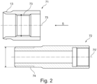
- Figure 2 shows a schematic view of a first part 71 and a second part 72 of a two-part adapter 71, 72 of a measuring cell 1 according to the invention.
- the first part 71 has an internal thread 73 arranged centrally and a locking lug 13 in the front area of the first part 71 as seen in the insertion direction S.
- the first part 71 has a continuous opening along its longitudinal axis 75.
- the first part 71 is rotationally symmetrical in relation to the longitudinal axis 75.
- the first part 71 can introduce axial forces into the measuring cell body when mounted or locked in place, but is freely rotatable.
- the second part 72 of the two-part adapter has an external thread 74 in the front area, as seen in the insertion direction S.
- the external thread 74 is designed such that it is screwed into the internal thread 73 of the first part when the adapter is assembled.
- the front area of the second part 72 is tapered compared to the rear area of the second part 72.
- the second part 72 has a continuous opening along its longitudinal axis 75'.
- the first part 71 is designed to be rotationally symmetrical along its longitudinal axis 75'.
- a surface of the second part 72 directed against the compression element 22 allows the transmission of compressive forces for pressing, but is rotationally symmetrical to the plugging direction S and transmits only low torques to the compression element 22 and the seal 23.
- Figure 1 further shows a system according to the invention comprising the two-part adapter 71, 72, and the measuring cell 4.
- Two connection adapters 30, 30' are arranged on the measuring cell 4, to which hoses or lines (not shown) for the fluid can be connected.
- a combination electrode 20 protrudes in its Figure 1 In the position shown when inserted in the plug-in direction S, less than a third of the length between the tip and the fastening thread of the combination electrode extends into the measuring chamber 4, in the specific embodiment up to the inlet opening 2 through which the fluid enters the measuring chamber 4. This achieves a minimization of the fluid volume in the measuring chamber 4 while simultaneously maximizing the measuring distance along the pH electrode.
- the section of the combination measuring chain 20 that extends into the measuring cell 1 is identified as the receiving section 21 and has a rod-shaped form, with the combination measuring chain 20 otherwise mainly having a circular cylindrical shape.
- the combination measuring chain 20 At its front end, as seen in the plug-in direction S, the combination measuring chain 20 consists of a tapered section and a spherical measuring tip 24.
- the combination measuring chain 20 or the rod-shaped receiving section 21 can be inserted through the insertion opening 6 into the measuring chamber 4 in the insertion direction S.
- a sealing ring 23 sits on the combination measuring chain 20 or the rod-shaped receiving section 21, which sits loosely during assembly and can thus be easily moved along the combination measuring chain 20.
- the sealing ring 23 does not yet have a sealing effect at this point, especially when fluid pressure is applied. This greatly simplifies the insertion of the combination measuring chain 20, but also the sliding of the sealing ring 23 onto the combination measuring chain 20, so that damage to the sensitive combination measuring chain 20 is avoided.
- the sealing ring 23 When plugging in, or at least in the plugged-in position, the sealing ring 23 rests against a support disk 11, which is inserted and preferably fixed in the position shown in Figure 5 before plugging in, in particular during the manufacture of the measuring cell body 5.
- the receiving section 21 is inserted through the support disk 11 until the two-part adapter 71, 72 surrounding the combination electrode 20 snaps into place on a shoulder 12 facing the combination electrode 20.
- locking lugs 13 are provided on the first adapter part 71.
- the adapter is already snapped into place before the combination electrode 20 is mounted.
- the support disk 11 forms a stop and the shoulder 13 forms a counter stop which is directed in the plug-in direction S and thus prevents the two-part adapter 71, 72 and the combination electrode 20 from being pulled out.
- the sealing ring 23 is held in its operating position and slightly compressed.
- the two-part adapter 71, 72 extends from the receiving section 21 to a fixing section 25 of the combination electrode 20 and thus effectively protects the combination electrode 20 from damage.
- a further sealing ring 23" is located in the fixing section 25 between the second adapter part 72 and the combination electrode 20.
- the assembly of the combination measuring chain 20 with the measuring cell 1 is extremely simple and by providing various two-part adapters 71, 72 and/or support disks 11 and/or support elements 22, the system can be used universally.
- Figure 3 shows schematically the support element 22 in a single view.
- the support element 22 is rotationally symmetrical to its longitudinal axis 75".
- the support element 22 has a through-opening along the longitudinal axis 75".
- the support element 22 has the compression surface 16 and a stop 27. In the assembled state, the stop 27 rests against the support disk 11 and the compression surface 16 compresses the sealing ring 23.
- a closure cap is first removed from the second adapter part 72.
- the combination measuring chain 20 is inserted into the two-part adapter 71, 72 and screwed in the fastening area 26 to the rear part of the second adapter part 72 in the fixing section 25.
- the sealing ring 23" is thereby compressed and seals the area between the second adapter part 72 and the combination measuring chain 20 in the fixing area 25.
- the second adapter part 72 is then screwed further into the first adapter part 71.
- the first adapter part 71 presses on the compression element 22 in the plug-in direction S.
- the compression element 22 therefore presses on the sealing ring 23 with the compression surface 16 in the plug-in direction S.
- the sealing ring 23 is thereby compressed and seals the area between the combination measuring chain 20 and the compression element 22.
Landscapes
- Chemical & Material Sciences (AREA)
- Life Sciences & Earth Sciences (AREA)
- Health & Medical Sciences (AREA)
- Biochemistry (AREA)
- General Physics & Mathematics (AREA)
- Electrochemistry (AREA)
- Physics & Mathematics (AREA)
- Analytical Chemistry (AREA)
- Molecular Biology (AREA)
- General Health & Medical Sciences (AREA)
- Chemical Kinetics & Catalysis (AREA)
- Immunology (AREA)
- Pathology (AREA)
- Investigating Or Analyzing Materials By The Use Of Electric Means (AREA)
- Investigating Or Analysing Biological Materials (AREA)
- Measuring Fluid Pressure (AREA)
- Investigating Or Analysing Materials By The Use Of Chemical Reactions (AREA)
- Investigating Or Analyzing Non-Biological Materials By The Use Of Chemical Means (AREA)
Claims (5)
- Cellule de mesure du pH (1), comprenant :- un espace de mesure (4) et au moins un orifice (2,3) pour un fluide,- un logement de mesure du pH (8), destiné à recevoir une portion de logement (21) en forme de barrette d'une électrode combinée (20) pour la mesure de la valeur pH du fluide dans l'espace de mesure (4), le logement de mesure du pH (8) comportant un orifice d'insertion (6) à travers lequel la portion de logement (21) peut être insérée dans une direction d'insertion (S),- un élément de compression (22) destiné à comprimer une bague d'étanchéité (23) de l'électrode combinée (20), placée dans la portion de logement (21), pour assurer l'étanchéité de l'espace de mesure (4) par rapport à l'environnement et- un adaptateur (71, 72), destiné à recevoir l'électrode combinée (20) dans une zone de fixation (26) de l'électrode combinée (20),caractérisée en ce que l'adaptateur (71, 72) est conçu en deux parties, avec une première partie d'adaptateur (71) et une deuxième partie d'adaptateur (72), la deuxième partie d'adaptateur (72) étant conçue pour recevoir l'électrode combinée (20) dans la zone de fixation (26) par un raccord vissé et en ce que la deuxième partie d'adaptateur (72) peut se visser dans la première partie d'adaptateur (71), par la première partie d'adaptateur (71), suite au vissage de la deuxième partie d'adaptateur (72), une pression pouvant être exercée sur l'élément de compression (22), du fait de la pression de la première partie d'adaptateur (71), la bague d'étanchéité (23) pouvant être comprimée par l'élément de compression (22) et l'étanchéité de l'espace de mesure (4) par rapport à l'environnement pouvant être assurée.
- Cellule de mesure (1) selon la revendication 1, l'élément de compression (22) étant conçu de forme annulaire et comportant une surface de compression (16) chanfreinée, la surface de compression (16) s'appuyant sur la bague d'étanchéité (23).
- Cellule de mesure (1) selon au moins l'une quelconque des revendications 1 à 2, la bague d'étanchéité (23) étant placée entre une bague de support (11) et l'élément de compression (22).
- Cellule de mesure (1) selon au moins l'une quelconque des revendications précédentes, dans laquelle l'espace de mesure (4) est constituée par un corps (5) de cellule de mesure sur lequel est surmoulé le logement de mesure du pH (8).
- Système, composé d'une cellule de mesure (1) selon au moins l'une quelconque des revendications 1 à 4 et d'une électrode combinée (20).
Priority Applications (6)
| Application Number | Priority Date | Filing Date | Title |
|---|---|---|---|
| ES20216664T ES3012961T3 (en) | 2020-12-22 | 2020-12-22 | Ph measuring cell |
| EP20216664.1A EP4019953B1 (fr) | 2020-12-22 | 2020-12-22 | Cellule de mesure de ph |
| EP24212269.5A EP4481334A3 (fr) | 2020-12-22 | 2020-12-22 | Cellule de mesure de ph |
| CN202180063351.5A CN116348758A (zh) | 2020-12-22 | 2021-10-27 | pH测量单元 |
| US18/025,421 US12449392B2 (en) | 2020-12-22 | 2021-10-27 | PH measuring cell |
| PCT/EP2021/079841 WO2022135774A1 (fr) | 2020-12-22 | 2021-10-27 | Cellule de mesure de ph |
Applications Claiming Priority (1)
| Application Number | Priority Date | Filing Date | Title |
|---|---|---|---|
| EP20216664.1A EP4019953B1 (fr) | 2020-12-22 | 2020-12-22 | Cellule de mesure de ph |
Related Child Applications (2)
| Application Number | Title | Priority Date | Filing Date |
|---|---|---|---|
| EP24212269.5A Division-Into EP4481334A3 (fr) | 2020-12-22 | 2020-12-22 | Cellule de mesure de ph |
| EP24212269.5A Division EP4481334A3 (fr) | 2020-12-22 | 2020-12-22 | Cellule de mesure de ph |
Publications (3)
| Publication Number | Publication Date |
|---|---|
| EP4019953A1 EP4019953A1 (fr) | 2022-06-29 |
| EP4019953C0 EP4019953C0 (fr) | 2025-01-22 |
| EP4019953B1 true EP4019953B1 (fr) | 2025-01-22 |
Family
ID=73856902
Family Applications (2)
| Application Number | Title | Priority Date | Filing Date |
|---|---|---|---|
| EP20216664.1A Active EP4019953B1 (fr) | 2020-12-22 | 2020-12-22 | Cellule de mesure de ph |
| EP24212269.5A Pending EP4481334A3 (fr) | 2020-12-22 | 2020-12-22 | Cellule de mesure de ph |
Family Applications After (1)
| Application Number | Title | Priority Date | Filing Date |
|---|---|---|---|
| EP24212269.5A Pending EP4481334A3 (fr) | 2020-12-22 | 2020-12-22 | Cellule de mesure de ph |
Country Status (5)
| Country | Link |
|---|---|
| US (1) | US12449392B2 (fr) |
| EP (2) | EP4019953B1 (fr) |
| CN (1) | CN116348758A (fr) |
| ES (1) | ES3012961T3 (fr) |
| WO (1) | WO2022135774A1 (fr) |
Families Citing this family (1)
| Publication number | Priority date | Publication date | Assignee | Title |
|---|---|---|---|---|
| EP4715037A1 (fr) * | 2024-09-23 | 2026-03-25 | Sartorius Stedim Biotech GmbH | Unité de mesure de cellule pour système de traitement de biopharma, système de traitement de biopharma et procédé d'échange de fluides dans un système de traitement de biopharma |
Family Cites Families (14)
| Publication number | Priority date | Publication date | Assignee | Title |
|---|---|---|---|---|
| GB1422343A (fr) * | 1972-06-29 | 1976-01-28 | ||
| US3959107A (en) * | 1974-06-06 | 1976-05-25 | Jack Edgar Horner | Combination electrode |
| US4012308A (en) * | 1975-11-07 | 1977-03-15 | Beckman Instruments, Inc. | Ion sensitive combination electrode |
| DE10019991C2 (de) * | 2000-04-22 | 2002-05-08 | Postberg Hans Juergen | Vorrichtung zum dichten Ein- und Herausführen eines Messwertgebers in ein bzw. aus einem Fluid in einem Rohr |
| DE10315338A1 (de) * | 2003-04-03 | 2004-10-14 | Mettler-Toledo Gmbh | Sicherungsvorrichtung für eine Einbauelektrodenvorrichtung |
| DE102004058863A1 (de) * | 2004-12-06 | 2006-06-08 | Endress + Hauser Conducta Gesellschaft für Mess- und Regeltechnik mbH | Adapter zur Elektrolytzufuhr für einen potentiometrischen Sensor |
| DE102006048898B4 (de) * | 2006-10-17 | 2010-09-09 | Knick Elektronische Messgeräte GmbH & Co. KG | Sondeneinrichtung zur Messung von Prozessgrößen, insbesondere Schubstangenarmatur |
| DE102006058069A1 (de) * | 2006-12-07 | 2008-06-19 | Mettler-Toledo Ag | Einbauelektrodenvorrichtung |
| JP5317854B2 (ja) * | 2009-06-29 | 2013-10-16 | 助川電気工業株式会社 | 導電性流体検知器 |
| US8568575B2 (en) * | 2009-09-02 | 2013-10-29 | Invensys Systems, Inc. | Adjustable, retractable probe insertion assembly |
| DE102011013003C5 (de) * | 2011-03-04 | 2021-01-07 | Optek-Danulat Gmbh | Durchströmbare pH-Messzelle |
| DE102012012528B4 (de) * | 2012-06-26 | 2014-02-20 | Krohne Messtechnik Gmbh | Messvorrichtung zum Bestimmen einer Prozessgröße |
| DE102012107099A1 (de) * | 2012-08-02 | 2014-02-06 | Haimer Gmbh | Auswucht- oder Messadapter |
| DE102017203616B4 (de) * | 2017-03-06 | 2022-02-03 | Knick Elektronische Messgeräte GmbH & Co. KG | Eintaucharmatur zur Positionierung von Messsensoren in Prozessflüssigkeiten |
-
2020
- 2020-12-22 EP EP20216664.1A patent/EP4019953B1/fr active Active
- 2020-12-22 EP EP24212269.5A patent/EP4481334A3/fr active Pending
- 2020-12-22 ES ES20216664T patent/ES3012961T3/es active Active
-
2021
- 2021-10-27 US US18/025,421 patent/US12449392B2/en active Active
- 2021-10-27 CN CN202180063351.5A patent/CN116348758A/zh active Pending
- 2021-10-27 WO PCT/EP2021/079841 patent/WO2022135774A1/fr not_active Ceased
Also Published As
| Publication number | Publication date |
|---|---|
| EP4019953C0 (fr) | 2025-01-22 |
| US20240011933A1 (en) | 2024-01-11 |
| US12449392B2 (en) | 2025-10-21 |
| EP4481334A3 (fr) | 2025-02-12 |
| WO2022135774A1 (fr) | 2022-06-30 |
| EP4019953A1 (fr) | 2022-06-29 |
| CN116348758A (zh) | 2023-06-27 |
| EP4481334A2 (fr) | 2024-12-25 |
| ES3012961T3 (en) | 2025-04-10 |
Similar Documents
| Publication | Publication Date | Title |
|---|---|---|
| EP0594808B1 (fr) | Dispositif permettant de mesurer la pression et la pression differentielle avec une boite filetee en trois parties et une corniere annulaire | |
| DE3341860C2 (de) | Meßkupplung für fluidische Systeme | |
| DE102009028663B4 (de) | Messgerät für die Prozessmesstechnik | |
| DE19628551A1 (de) | Druckmeßgerät und Druckmeßanordnung | |
| CH701837B1 (de) | Einbauelektrodenvorrichtung. | |
| WO1996008669A1 (fr) | Raccord pour la piece d'accouplement des tuyaux d'un appareil de nettoyage a haute pression | |
| EP2232108B1 (fr) | Dispositif de fermeture pour la fermeture etanche d'un systeme de remplissage et de vidage de wagon-citerne ou de citerne de transport | |
| DE102016114565A1 (de) | Messanordnung | |
| EP1332313A1 (fr) | Raccord pour conduites flexibles en plastique, comportant un systeme de capteurs | |
| EP2569602B1 (fr) | Ensemble permettant de relier un appareil de mesure à un récipient contenant le fluide à mesurer | |
| DE102021112448B3 (de) | Messanordnung, Montagesystem und Verfahren zur Druckmessung in einem Messvolumen | |
| DE102005040699B3 (de) | Temperaturmessvorrichtung | |
| WO1998057136A1 (fr) | Boitier de detecteur avec raccord pour fluide de processus | |
| DE19752528C2 (de) | Anschlußsteckvorrichtung für Kunststoffrohre | |
| EP4019953B1 (fr) | Cellule de mesure de ph | |
| EP3007757B1 (fr) | Utilisation d'un élément de liaison et ensemble de liaison | |
| DE102011013003C5 (de) | Durchströmbare pH-Messzelle | |
| DE29819377U1 (de) | Befestigungsvorrichtung | |
| DE102016008419A1 (de) | Temperatursensorvorrichtung | |
| DE4120752A1 (de) | Messgeraetgehaeuse | |
| DE19937332C5 (de) | Klemmvorrichtung | |
| DE102008049152A1 (de) | Drehbares Instrumentengehäuse | |
| DE102010022490B4 (de) | Druckmessvorrichtung mit einem zweiteilig aufgebauten Anschluss an ein druckführendes Prozesssystem | |
| EP0613552A1 (fr) | Bride de raccordement a un processus de traitement pour transducteurs de pression | |
| DE102012105551B4 (de) | Gehäuse für ein Feldgerät und Feldgerät mit einem solchen Gehäuse |
Legal Events
| Date | Code | Title | Description |
|---|---|---|---|
| PUAI | Public reference made under article 153(3) epc to a published international application that has entered the european phase |
Free format text: ORIGINAL CODE: 0009012 |
|
| STAA | Information on the status of an ep patent application or granted ep patent |
Free format text: STATUS: THE APPLICATION HAS BEEN PUBLISHED |
|
| AK | Designated contracting states |
Kind code of ref document: A1 Designated state(s): AL AT BE BG CH CY CZ DE DK EE ES FI FR GB GR HR HU IE IS IT LI LT LU LV MC MK MT NL NO PL PT RO RS SE SI SK SM TR |
|
| STAA | Information on the status of an ep patent application or granted ep patent |
Free format text: STATUS: REQUEST FOR EXAMINATION WAS MADE |
|
| 17P | Request for examination filed |
Effective date: 20221221 |
|
| RBV | Designated contracting states (corrected) |
Designated state(s): AL AT BE BG CH CY CZ DE DK EE ES FI FR GB GR HR HU IE IS IT LI LT LU LV MC MK MT NL NO PL PT RO RS SE SI SK SM TR |
|
| GRAP | Despatch of communication of intention to grant a patent |
Free format text: ORIGINAL CODE: EPIDOSNIGR1 |
|
| STAA | Information on the status of an ep patent application or granted ep patent |
Free format text: STATUS: GRANT OF PATENT IS INTENDED |
|
| INTG | Intention to grant announced |
Effective date: 20241017 |
|
| GRAS | Grant fee paid |
Free format text: ORIGINAL CODE: EPIDOSNIGR3 |
|
| GRAA | (expected) grant |
Free format text: ORIGINAL CODE: 0009210 |
|
| STAA | Information on the status of an ep patent application or granted ep patent |
Free format text: STATUS: THE PATENT HAS BEEN GRANTED |
|
| AK | Designated contracting states |
Kind code of ref document: B1 Designated state(s): AL AT BE BG CH CY CZ DE DK EE ES FI FR GB GR HR HU IE IS IT LI LT LU LV MC MK MT NL NO PL PT RO RS SE SI SK SM TR |
|
| REG | Reference to a national code |
Ref country code: GB Ref legal event code: FG4D Free format text: NOT ENGLISH |
|
| REG | Reference to a national code |
Ref country code: CH Ref legal event code: EP |
|
| REG | Reference to a national code |
Ref country code: IE Ref legal event code: FG4D Free format text: LANGUAGE OF EP DOCUMENT: GERMAN |
|
| REG | Reference to a national code |
Ref country code: DE Ref legal event code: R096 Ref document number: 502020010250 Country of ref document: DE |
|
| U01 | Request for unitary effect filed |
Effective date: 20250122 |
|
| U07 | Unitary effect registered |
Designated state(s): AT BE BG DE DK EE FI FR IT LT LU LV MT NL PT RO SE SI Effective date: 20250128 |
|
| REG | Reference to a national code |
Ref country code: ES Ref legal event code: FG2A Ref document number: 3012961 Country of ref document: ES Kind code of ref document: T3 Effective date: 20250410 |
|
| PG25 | Lapsed in a contracting state [announced via postgrant information from national office to epo] |
Ref country code: RS Free format text: LAPSE BECAUSE OF FAILURE TO SUBMIT A TRANSLATION OF THE DESCRIPTION OR TO PAY THE FEE WITHIN THE PRESCRIBED TIME-LIMIT Effective date: 20250422 |
|
| PG25 | Lapsed in a contracting state [announced via postgrant information from national office to epo] |
Ref country code: PL Free format text: LAPSE BECAUSE OF FAILURE TO SUBMIT A TRANSLATION OF THE DESCRIPTION OR TO PAY THE FEE WITHIN THE PRESCRIBED TIME-LIMIT Effective date: 20250122 |
|
| PG25 | Lapsed in a contracting state [announced via postgrant information from national office to epo] |
Ref country code: NO Free format text: LAPSE BECAUSE OF FAILURE TO SUBMIT A TRANSLATION OF THE DESCRIPTION OR TO PAY THE FEE WITHIN THE PRESCRIBED TIME-LIMIT Effective date: 20250422 Ref country code: IS Free format text: LAPSE BECAUSE OF FAILURE TO SUBMIT A TRANSLATION OF THE DESCRIPTION OR TO PAY THE FEE WITHIN THE PRESCRIBED TIME-LIMIT Effective date: 20250522 |
|
| PG25 | Lapsed in a contracting state [announced via postgrant information from national office to epo] |
Ref country code: HR Free format text: LAPSE BECAUSE OF FAILURE TO SUBMIT A TRANSLATION OF THE DESCRIPTION OR TO PAY THE FEE WITHIN THE PRESCRIBED TIME-LIMIT Effective date: 20250122 |
|
| PG25 | Lapsed in a contracting state [announced via postgrant information from national office to epo] |
Ref country code: GR Free format text: LAPSE BECAUSE OF FAILURE TO SUBMIT A TRANSLATION OF THE DESCRIPTION OR TO PAY THE FEE WITHIN THE PRESCRIBED TIME-LIMIT Effective date: 20250423 |
|
| PG25 | Lapsed in a contracting state [announced via postgrant information from national office to epo] |
Ref country code: SM Free format text: LAPSE BECAUSE OF FAILURE TO SUBMIT A TRANSLATION OF THE DESCRIPTION OR TO PAY THE FEE WITHIN THE PRESCRIBED TIME-LIMIT Effective date: 20250122 |
|
| PG25 | Lapsed in a contracting state [announced via postgrant information from national office to epo] |
Ref country code: SK Free format text: LAPSE BECAUSE OF FAILURE TO SUBMIT A TRANSLATION OF THE DESCRIPTION OR TO PAY THE FEE WITHIN THE PRESCRIBED TIME-LIMIT Effective date: 20250122 |
|
| PLBE | No opposition filed within time limit |
Free format text: ORIGINAL CODE: 0009261 |
|
| STAA | Information on the status of an ep patent application or granted ep patent |
Free format text: STATUS: NO OPPOSITION FILED WITHIN TIME LIMIT |
|
| REG | Reference to a national code |
Ref country code: CH Ref legal event code: L10 Free format text: ST27 STATUS EVENT CODE: U-0-0-L10-L00 (AS PROVIDED BY THE NATIONAL OFFICE) Effective date: 20251203 |
|
| 26N | No opposition filed |
Effective date: 20251023 |
|
| REG | Reference to a national code |
Ref country code: CH Ref legal event code: U11 Free format text: ST27 STATUS EVENT CODE: U-0-0-U10-U11 (AS PROVIDED BY THE NATIONAL OFFICE) Effective date: 20260101 |
|
| PGFP | Annual fee paid to national office [announced via postgrant information from national office to epo] |
Ref country code: GB Payment date: 20251218 Year of fee payment: 6 |
|
| U20 | Renewal fee for the european patent with unitary effect paid |
Year of fee payment: 6 Effective date: 20251208 |
|
| PGFP | Annual fee paid to national office [announced via postgrant information from national office to epo] |
Ref country code: IE Payment date: 20251218 Year of fee payment: 6 Ref country code: CZ Payment date: 20251209 Year of fee payment: 6 |
|
| PGFP | Annual fee paid to national office [announced via postgrant information from national office to epo] |
Ref country code: ES Payment date: 20260119 Year of fee payment: 6 |
|
| PGFP | Annual fee paid to national office [announced via postgrant information from national office to epo] |
Ref country code: CH Payment date: 20260101 Year of fee payment: 6 |