EP4019993B1 - Procédé et appareil de détection de court-circuit de batterie - Google Patents
Procédé et appareil de détection de court-circuit de batterie Download PDFInfo
- Publication number
- EP4019993B1 EP4019993B1 EP21186088.7A EP21186088A EP4019993B1 EP 4019993 B1 EP4019993 B1 EP 4019993B1 EP 21186088 A EP21186088 A EP 21186088A EP 4019993 B1 EP4019993 B1 EP 4019993B1
- Authority
- EP
- European Patent Office
- Prior art keywords
- short circuit
- battery
- threshold
- state
- state indicator
- Prior art date
- Legal status (The legal status is an assumption and is not a legal conclusion. Google has not performed a legal analysis and makes no representation as to the accuracy of the status listed.)
- Active
Links
Images





Classifications
-
- G—PHYSICS
- G01—MEASURING; TESTING
- G01R—MEASURING ELECTRIC VARIABLES; MEASURING MAGNETIC VARIABLES
- G01R31/00—Arrangements for testing electric properties; Arrangements for locating electric faults; Arrangements for electrical testing characterised by what is being tested not provided for elsewhere
- G01R31/36—Arrangements for testing, measuring or monitoring the electrical condition of accumulators or electric batteries, e.g. capacity or state of charge [SoC]
- G01R31/385—Arrangements for measuring battery or accumulator variables
-
- H—ELECTRICITY
- H02—GENERATION; CONVERSION OR DISTRIBUTION OF ELECTRIC POWER
- H02J—ELECTRIC POWER NETWORKS; CIRCUIT ARRANGEMENTS OR SYSTEMS FOR SUPPLYING OR DISTRIBUTING ELECTRIC POWER; SYSTEMS FOR STORING ELECTRIC ENERGY
- H02J7/00—Circuit arrangements for charging or discharging batteries or for supplying loads from batteries
- H02J7/80—Circuit arrangements for charging or discharging batteries or for supplying loads from batteries including monitoring or indicating arrangements
- H02J7/84—Control of state of health [SOH]
-
- G—PHYSICS
- G01—MEASURING; TESTING
- G01R—MEASURING ELECTRIC VARIABLES; MEASURING MAGNETIC VARIABLES
- G01R31/00—Arrangements for testing electric properties; Arrangements for locating electric faults; Arrangements for electrical testing characterised by what is being tested not provided for elsewhere
- G01R31/36—Arrangements for testing, measuring or monitoring the electrical condition of accumulators or electric batteries, e.g. capacity or state of charge [SoC]
- G01R31/367—Software therefor, e.g. for battery testing using modelling or look-up tables
-
- G—PHYSICS
- G01—MEASURING; TESTING
- G01R—MEASURING ELECTRIC VARIABLES; MEASURING MAGNETIC VARIABLES
- G01R31/00—Arrangements for testing electric properties; Arrangements for locating electric faults; Arrangements for electrical testing characterised by what is being tested not provided for elsewhere
- G01R31/36—Arrangements for testing, measuring or monitoring the electrical condition of accumulators or electric batteries, e.g. capacity or state of charge [SoC]
- G01R31/374—Arrangements for testing, measuring or monitoring the electrical condition of accumulators or electric batteries, e.g. capacity or state of charge [SoC] with means for correcting the measurement for temperature or ageing
-
- G—PHYSICS
- G01—MEASURING; TESTING
- G01R—MEASURING ELECTRIC VARIABLES; MEASURING MAGNETIC VARIABLES
- G01R31/00—Arrangements for testing electric properties; Arrangements for locating electric faults; Arrangements for electrical testing characterised by what is being tested not provided for elsewhere
- G01R31/36—Arrangements for testing, measuring or monitoring the electrical condition of accumulators or electric batteries, e.g. capacity or state of charge [SoC]
- G01R31/382—Arrangements for monitoring battery or accumulator variables, e.g. SoC
-
- G—PHYSICS
- G01—MEASURING; TESTING
- G01R—MEASURING ELECTRIC VARIABLES; MEASURING MAGNETIC VARIABLES
- G01R31/00—Arrangements for testing electric properties; Arrangements for locating electric faults; Arrangements for electrical testing characterised by what is being tested not provided for elsewhere
- G01R31/36—Arrangements for testing, measuring or monitoring the electrical condition of accumulators or electric batteries, e.g. capacity or state of charge [SoC]
- G01R31/382—Arrangements for monitoring battery or accumulator variables, e.g. SoC
- G01R31/3835—Arrangements for monitoring battery or accumulator variables, e.g. SoC involving only voltage measurements
-
- G—PHYSICS
- G01—MEASURING; TESTING
- G01R—MEASURING ELECTRIC VARIABLES; MEASURING MAGNETIC VARIABLES
- G01R31/00—Arrangements for testing electric properties; Arrangements for locating electric faults; Arrangements for electrical testing characterised by what is being tested not provided for elsewhere
- G01R31/36—Arrangements for testing, measuring or monitoring the electrical condition of accumulators or electric batteries, e.g. capacity or state of charge [SoC]
- G01R31/392—Determining battery ageing or deterioration, e.g. state of health
-
- G—PHYSICS
- G01—MEASURING; TESTING
- G01R—MEASURING ELECTRIC VARIABLES; MEASURING MAGNETIC VARIABLES
- G01R31/00—Arrangements for testing electric properties; Arrangements for locating electric faults; Arrangements for electrical testing characterised by what is being tested not provided for elsewhere
- G01R31/50—Testing of electric apparatus, lines, cables or components for short-circuits, continuity, leakage current or incorrect line connections
- G01R31/52—Testing for short-circuits, leakage current or ground faults
-
- G—PHYSICS
- G01—MEASURING; TESTING
- G01R—MEASURING ELECTRIC VARIABLES; MEASURING MAGNETIC VARIABLES
- G01R31/00—Arrangements for testing electric properties; Arrangements for locating electric faults; Arrangements for electrical testing characterised by what is being tested not provided for elsewhere
- G01R31/36—Arrangements for testing, measuring or monitoring the electrical condition of accumulators or electric batteries, e.g. capacity or state of charge [SoC]
- G01R31/396—Acquisition or processing of data for testing or for monitoring individual cells or groups of cells within a battery
Definitions
- the following description relates to a method and apparatus with battery short circuit detection.
- a short circuit of a battery may degrade the battery's efficiency and also be the main cause of thermal runaway of the battery, raising a safety issue such as an explosion.
- a battery needs to effectively detect a short circuit before there is an increase in physical or thermal deformation of the battery caused by the short circuit, thus, ensuring the safety of the battery.
- the following methods are generally used-for example, a method using a change in a current, a voltage, a capacity, a temperature, and the like of the battery, a method using a change in various parameters of an electric circuit model, and a method using various deviation values between unit cells included in a multi-cell to detect a short circuit in a multi-cell battery pack.
- cell state of charge, SOC differences with the mean SOC for a battery pack are estimated by extended Kalman filter.
- the evaluated SOC difference can track the actual value well.
- an MSC diagnostic method is developed by employing recursive least squares filter.
- a short circuit detection method includes obtaining battery data associated with a state of a battery from a charging cycle of the battery, estimating an error in the battery data using an estimation model, determining a state indicator corresponding to the error in the battery data, and detecting a short circuit of the battery based on a result of comparing the state indicator and a short circuit threshold.
- the method may further include performing an aging correction based on a result of comparing the state indicator and an aging threshold.
- the detecting of the short circuit may include comparing an age state indicator, based on the aging correction, to the short circuit threshold.
- a sign of the short circuit threshold may be different than a sign of the aging threshold.
- the performing of the aging correction may include updating either one or both of the estimation model and the state indicator based on an aging state of the battery.
- the aging state of the battery may be obtained from measured data.
- the aging state of the battery may be obtained from measured data generated by any one or more of inducing a short circuit in the battery, simulating a short circuit state in the battery, or simulating an aging state in the battery.
- the detecting of the short circuit may include determining a difference indicator based on a difference between the state indicator and a previous state indicator of a previous charging cycle, and detecting the short circuit of the battery based on a result of comparing the difference indicator and a difference threshold.
- the confidence range may be between a positive confidence threshold and a negative confidence threshold.
- the method may further include determining a discharging state indicator from a discharging cycle of the battery, determining a discharging difference indicator based on a difference between the discharging state indicator and a previous discharging state indicator of a previous discharging cycle of the battery, and detecting the short circuit of the battery based on a result of comparing the discharging difference indicator and a discharging difference threshold.
- the short circuit threshold may have a different value in each charging interval of the charging cycle, and the charging interval includes a constant current (CC) interval and a constant voltage (CV) interval.
- CC constant current
- CV constant voltage
- the state of the battery may correspond to a voltage of the battery, and the battery data may correspond to a measured value of the voltage.
- the estimating of the error may include determining an estimated value of the voltage using the estimation model, and estimating the error based on a difference between the measured value and the estimated value.
- the estimation model may be an electrochemical model.
- a non-transitory computer-readable storage medium may store instructions that, when executed by one or more processors, configure the one or more processors to perform the method above.
- a short circuit detection apparatus may include one or more processors, and a memory configured to store instructions executable in the one or more processors.
- the one or more processors may be configured to obtain battery data associated with a state of a battery from a charging cycle of the battery, estimate an error in the battery data using an estimation model, determine a state indicator corresponding to the error in the battery data, and detect a short circuit of the battery based on a result of comparing the state indictor and a short circuit threshold.
- the one or more processors may be configured to perform an aging correction based on a result of comparing the state indicator and an aging threshold.
- the one or more processors may be configured to compare an age state indicator, based on the aging correction, to the short circuit threshold.
- a sign of the short circuit threshold may be different than a sign of the aging threshold.
- the short circuit threshold may be a different value in each charging interval of the charging cycle, and the charging interval may include a constant current (CC) interval and a constant voltage (CV) interval.
- CC constant current
- CV constant voltage
- an electronic apparatus in another general aspect, includes a battery configured to supply power, and one or more processors configured to obtain battery data associated with a state of a battery from a charging cycle of the battery, estimate an error in the battery data using an estimation model, determine a state indicator corresponding to the error in the battery data, and detect a short circuit of the battery based on a result of comparing the state indicator and a short circuit threshold.
- the one or more processors may be configured to perform an aging correction based on a result of comparing the state indicator and an aging threshold.
- the one or more processors may be configured to compare an age state indicator, based on the aging correction, to the short circuit threshold.
- a sign of the short circuit threshold is different than a sign of the aging threshold.
- first,” “second,” and “third” may be used herein to describe various members, components, regions, layers, or sections, these members, components, regions, layers, or sections are not to be limited by these terms. Rather, these terms are only used to distinguish one member, component, region, layer, or section from another member, component, region, layer, or section. Thus, a first member, component, region, layer, or section referred to in examples described herein may also be referred to as a second member, component, region, layer, or section without departing from the teachings of the examples.
- spatially relative terms such as “above,” “upper,” “below,” and “lower” may be used herein for ease of description to describe one element's relationship to another element as shown in the figures. Such spatially relative terms are intended to encompass different orientations of the device in use or operation in addition to the orientation depicted in the figures. For example, if the device in the figures is turned over, an element described as being “above” or “upper” relative to another element will then be “below” or “lower” relative to the other element. Thus, the term “above” encompasses both the above and below orientations depending on the spatial orientation of the device.
- the device may also be oriented in other ways (for example, rotated 90 degrees or at other orientations), and the spatially relative terms used herein are to be interpreted accordingly.
- FIG. 1 illustrates an example of an overall operation of a short circuit detection apparatus.
- a short circuit detection apparatus 100 may receive battery data 101 and output a detection result 102 using an estimation model 110.
- the battery data 101 may include data associated with the specification and/or operation of a battery monitored by the short circuit detection apparatus 100.
- the battery data 101 may include state information of the battery based on the charging.
- the battery data 101 may include state information of the battery based on the discharging.
- the state information may include information associated with, for example, a voltage, a current, and a temperature of the battery.
- the battery data 101 may be measured through various sensors inside and/or outside of the battery.
- the short circuit detection apparatus 100 may estimate an error in the battery data 101 using the estimation model 110.
- the short circuit detection apparatus 100 may analyze the cause of the error.
- the short circuit detection apparatus 100 may output the detection result 102 associated with the short circuit.
- the detection result 102 may include short circuit information associated with, for example, whether the short circuit is detected, a point in time at which the short circuit is detected, a time for which the short circuit lasts, and an intensity of the short circuit.
- the short circuit detection apparatus 100 may define a state indicator that indicates the state of the battery using the error in the battery data 101.
- the estimation model 110 may be an electrochemical model (e.g., an electrochemical-thermal (ECT) model), and the short circuit detection apparatus 100 may determine an estimated value of a voltage of the battery using the ECT model.
- the ECT model may simulate an internal state of the battery using various ECT parameters and governing equations.
- the parameters of the ECT model may represent, for example, a shape (e.g., thickness, radius, etc.), an open circuit potential (OCP), a physical property (e.g., electrical conductance, ionic conductance, diffusion coefficient, etc.).
- the governing equations may include, for example, an electrochemical reaction occurring in an electrode and the surface of an electrolyte based on the parameters, and a physical conservation equation associated with the electrode, the concentration of the electrolyte, and the conservation of electric charges.
- the ECT model may determine an estimated voltage based on a measured voltage (or a measured voltage and a measured temperature).
- the short circuit detection apparatus 100 may determine the state indicator based on a difference between the battery data 101 corresponding to a measured value of a voltage of the battery and an estimated value of the estimation model 110. For example, the short circuit detection apparatus 100 may use, as the state indicator, the difference between the measured value and the estimated value, or (measured value - estimated value).
- the estimation model 110 may be an electric circuit model. Similar to the ECT model, the electric circuit model may determine the state indicator based on a difference between estimated voltages.
- the short circuit detection apparatus 100 may use, as the state indicator, a corrected value (e.g., a corrected value of a state of charge (SOC)) of a corrector configured to correct the difference between the battery data 101 and the estimation model 110.
- a corrected value e.g., a corrected value of a state of charge (SOC)
- SOC state of charge
- the short circuit detection apparatus 100 may detect a short circuit using thresholds set through preliminary experiments (hereinafter pre-experiments) performed beforehand.
- the thresholds may include, for example, a short circuit threshold, an aging threshold, and a difference threshold.
- the short circuit threshold refers to a threshold value used to detect a short circuit.
- the short circuit detection apparatus 100 may detect a short circuit based on a result of comparing the state indicator and the short circuit threshold. In a case in which the battery is degraded (or aged), the influence of such degradation or aging may be applied to the state indicator, which may compromise the accuracy in detecting a short circuit.
- the aging threshold refers to a threshold value used to verify whether there is aging in the battery.
- the short circuit detection apparatus 100 may perform an aging correction based on a result of comparing the state indicator and the aging threshold. Through a relatively high level of accuracy in the estimation of the ECT model and a continuous aging correction, it is possible to maintain a relatively high level of accuracy in detecting a short circuit using the short circuit threshold.
- the short circuit threshold is set to be a level that enables the detection of a micro-short-circuit (MSC)
- the short circuit detection apparatus 100 may detect an MSC at an initial stage of the occurrence of a short circuit, using such a short circuit threshold described above.
- a short circuit occurring inside or outside the battery may involve self-discharging of the battery.
- a voltage drop, a decrease in a charging speed, an increase in a charging amount, and the like may occur in the charging process.
- a discharging process a voltage drop, an increase in a discharging speed, a decrease in a discharging amount, and the like may occur.
- a resting process there may occur a voltage drop.
- the charging speed may increase due to increased resistance and decreased capacity, for example.
- the state (e.g., a voltage) of the battery may change in opposite directions due to a short circuit and aging. For example, the battery's voltage may decrease when a short circuit occurs and increase when aging occurs.
- the aging correction may be performed to remove such an influence of the aging, thereby maintaining short circuit detection performance.
- the state (e.g., a voltage) of the battery may change in the same direction due to a short circuit and aging. Based on this, it may not be possible to identify whether a change in the state indicator is due to a short circuit or aging. In such a case, a short circuit and/or aging may not be detected through a direct comparison between the state indicator and the short circuit threshold and/or the aging threshold. Instead, the short circuit detection apparatus 100 may detect a short circuit and/or aging by comparing, to a difference threshold, a difference (also referred to as a difference indicator) between corresponding state indicators in different cycles.
- a difference threshold also referred to as a difference indicator
- a short circuit detection method based on such a difference threshold may be used even in the charging process.
- setting each threshold and detecting a short circuit using set thresholds will be described in detail.
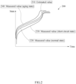
- FIG. 2 illustrates an example of pre-experimental data.
- graph 200 indicates pre-experimental data of a charging process, hereinafter simply a charging experiment data.
- the pre-experimental data may indicate a change in a state (e.g., a voltage) of a battery over time and include estimated data 210 indicating an estimated value of a normal state, measured data 220 indicating a measured value of the normal state, measured data 230 indicating a measured value of a short circuit state, and measured data 240 indicating a measured value of an aging state.
- the estimated data 210 may be obtained using an estimation model (e.g., an ECT model) and the measured data 220.
- an estimation model e.g., an ECT model
- the measured data 220, 230, and 240 may be obtained by making a change in the state of the battery, such as, for example, a depth of discharge (DoD) and a maximum charging capacity.
- the measured data 220 may be generated using the battery in the normal state.
- the measured data 230 and 240 may be generated by directly inducing a short circuit and aging in the battery or by simulating a short circuit state and an aging state through a simulating device such as a resistor.
- a simulating device such as a resistor.
- a state indicator and a threshold value may be set using such pre-experimental data.
- FIG. 3 illustrates an example of a state indicator and a threshold corresponding to the pre-experimental data of FIG. 2 .
- the graph 300 includes a normal state indicator 310 of a normal state, an aging state indicator 320 of an aging state, and a short circuit state indicator 330 of a short circuit state, based on Q (time or SOC).
- the state indicator 310 may be determined through (a measured value of the normal state (e.g., the measured data 220 of FIG. 2 ) - an estimated value of the normal state (e.g., the estimated data 210 of FIG. 2 )).
- the state indicator 320 may be determined through (a measured value of the aging state (e.g., the measured data 240 of FIG.
- the state indicator 330 may be determined through (a measured value of the short circuit state (e.g., the measured data 230 of FIG. 2 ) - the estimated value of the normal state (e.g., the estimated data 210)).
- a measured value of the short circuit state e.g., the measured data 230 of FIG. 2
- the estimated value of the normal state e.g., the estimated data 210)
- "-" denotes a subtraction sign.
- the normal state indicator 310 may have values approximate to 0 on the whole, which indicates that an error of an estimation model is not great.
- the aging state indicator 320 may have values inclined to a positive (+) direction on the whole, which is due to the influence of a change (e.g., a voltage rise) in a measured value by aging.
- the short circuit state indicator 330 may have values inclined to a negative (-) direction on the whole, which is due to the influence of a change (e.g., a voltage drop) in a measured value by a short circuit.
- a change in a state indicator may have opposite directions depending on whether the change is from aging or a short circuit.
- a change in a state indicator may have opposite directions with respect to aging and a short circuit even when the state indicator is derived through (an estimated value - a measured value) or through other state values such as a SOC instead of a voltage.
- the state indicator may be defined in various ways using such a characteristic.
- various thresholds may be determined based on characteristics of the state indicators 310, 320, and 330.
- the thresholds may be determined to follow respective changing patterns of the state indicators 310, 320, and 330, or be set as representative values of the state indicators 310, 320, and 330.
- various values such as a maximum value, a minimum value, a mean value, and a median value may be used as the representative values.
- Graph 301 indicates thresholds 311, 312, 321, and 331 that follow the changing patterns of the state indicators 310, 320, and 330.
- an aging threshold 311 and a short circuit threshold 312 may be set based on the normal state indicator 310.
- the aging threshold 311 and the short circuit threshold 312 may be set to follow the changing pattern of the normal state indicator 310 while maintaining a regular interval with the normal state indicator 310.
- an aging threshold 321 may be set to follow the changing pattern of the aging state indicator 320.
- a short circuit threshold 331 may be set to follow the changing pattern of the short circuit indicator 330.
- a short circuit detection apparatus may determine a state indicator of battery data obtained during an operation of a battery, and detect the occurrence of a short circuit and/or aging by comparing the state indicator and thresholds (e.g., the thresholds 311, 312, 321, and 331).
- the short circuit detection apparatus may determine that there is aging. In a case in which the state indicator decreases under the short circuit threshold 312 or 331, the short circuit detection apparatus may determine that there is a short circuit.
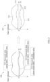
- FIG. 4 illustrates other examples of a threshold.
- respective thresholds in graphs 401, 402, and 403 are derived through state indicators 410, 420, and 430 in graph 400.
- the state indicators 410, 420, and 430 may respectively correspond to the state indicators 310, 320, and 330 of FIG. 3 .
- the thresholds in the graphs 401, 402, and 403 may be derived through various representative values of the state indicators 410, 420, and 430.
- an aging threshold 421 may correspond to a mean or median value of the aging state indicator 420.
- a short circuit threshold 431 may correspond to a mean or median value of the short circuit state indicator 430.
- an aging threshold 411 may correspond to a maximum value of the normal state indicator 410
- a short circuit threshold 412 may correspond to a minimum value of the normal state indicator 410.
- a different threshold may be applied to each charging interval based on a charging mode.
- the charging mode may include, for example, a constant current (CC) mode, a constant voltage (CV) mode, a constant power (CP) mode.
- CC constant current
- CV constant voltage
- CP constant power
- thresholds in the graph 403 may have different values in each of a charging interval in the CC mode and a charging interval in the CV mode.
- a first aging threshold 413 or 422 may be derived from a CC interval
- a second aging threshold 414 or 423 may be derived from a CV interval.
- a first short circuit threshold 415 or 432 may be derived from the CC interval
- a second short circuit threshold 416 or 433 may be derived from the CV interval.
- a threshold associated with the CP mode may have a distinguishing value.
- a short circuit detection apparatus may detect a short circuit and/or aging using a value of the threshold corresponding to each interval. For example, the short circuit detection apparatus may compare a state indicator associated with battery data in the CC interval to the first aging threshold 413 or 422 and/or the first short circuit threshold 415 or 432. In addition, the short circuit detection apparatus may compare a state indicator associated with battery data in the CV interval to the second aging threshold 414 or 423 and/or the second short circuit threshold 416 or 433.
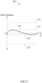
- FIG. 5 illustrates an example of a state indicator corresponding to operational data.
- graph 500 includes a state indicator 510 corresponding to operational data, an aging threshold 531, a short circuit threshold 532, and confidence thresholds 521 and 522.
- the operational data refers to battery data that is obtained as a battery operates during actual use of an electronic apparatus powered by the battery, and is distinguished from pre-experimental data obtained from a pre-experiment.
- a short circuit detection apparatus e.g., the short circuit detection apparatus 100 of FIG.
- the aging threshold 531 and the short circuit threshold 532 may have opposite signs to each other.
- the confidence thresholds 521 and 522 include a positive confidence threshold 521 and a negative confidence threshold 522, and an interval between the positive confidence threshold 521 and the negative confidence threshold 522 may be referred to herein as a confidence interval.
- the confidence thresholds 521 and 522 may be confidence limits on a short circuit and/or aging detecting method based on a direct comparison with the aging threshold 531 and/or the short circuit threshold 532. For example, in a case in which the state indicator 510 is out of the confidence interval, defined by the confidence thresholds 521 and 522, the method may be determined not to be trusted.
- the short circuit detection apparatus may detect aging and/or a short circuit by comparing, to a difference threshold, a difference between corresponding state indicators included in different cycles. For the aging threshold 531 and short circuit threshold 532, their signs may be changed based on which state indicator is used.
- FIG. 6 illustrates an example of a change in a state indicator by an aging correction.
- graph 600 includes a first state indicator 610 before an aging correction is performed and a second state indicator 620 after the aging correction is performed.
- a short circuit detection apparatus may perform the aging correction by applying an aging state of a battery.
- the aging correction may include updating an estimation model and/or the first state indicator 610.
- the second state indicator 620 may correspond to a state indicator before aging occurs, and the short circuit detection apparatus may update a parameter of the estimation model (e.g., an ECT model) such that the first state indicator 610 is initialized to be the second state indicator 620.
- a parameter of the estimation model e.g., an ECT model
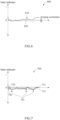
- FIG. 7 illustrates an example of a detected short circuit point.
- an aging threshold 711 and a short circuit threshold 712 may be set based on a state indicator 710 of pre-experimental data.
- the state indicator 710 may be a normal state indicator of the pre-experimental data.
- a short circuit detection apparatus may detect aging and/or a short circuit by comparing a state indicator 720 of the operational data to the aging threshold 711 and/or the short circuit threshold 712. When aging is detected, the short circuit detection apparatus may perform an aging correction described above with reference to FIG. 6 , and thus maintain the validity of the short circuit threshold 712.
- the short circuit detection apparatus may detect a short circuit in real time by directly comparing the state indicator 720 and the short circuit threshold 712. For example, the short circuit detection apparatus may detect a short circuit at points 721 that deviate from the short circuit threshold 712 in a negative direction.
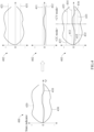
- FIG. 8 illustrates an example of determining a charging difference threshold.
- a first state indicator 810 is obtained from a first charging experiment cycle of a normal state
- a second state indicator 820 is obtained from a second charging experiment cycle of a short circuit state.
- the charging experiment cycles may correspond to a pre-experiment performed in advance, and a second charging cycle may proceed in a situation in which a desired short circuit condition is simulated using a simulating device such as a resistor.
- a difference value 830 may correspond to a maximum difference between the first state indicator 810 and the second state indicator 820. Based on the difference value 830, a difference threshold may be set.
- a difference threshold used in a charging process may be referred to herein as a charging difference threshold. The difference threshold may be set for each charging interval or for an entire charging interval.
- a short circuit detection apparatus may detect a short circuit by comparing, to the charging difference threshold, a difference between state indicators in charging operation cycles.
- the difference between these state indicators may be referred to herein as a difference indicator.
- the short circuit detection apparatus may determine a difference indicator based on a difference between a state indicator in a first charging operation cycle (e.g., a current charging operation cycle) and a state indicator in a second charging operation cycle (e.g., a previous charging operation cycle), and detect a short circuit based on a result of comparing the difference indicator and the difference threshold.
- Such different charging cycles as the first charging cycle (experiment or operation) and the second charging cycle (experiment or operation) may refer to charging cycles that proceed at different times.
- these charging cycles may correspond to the same charging region.
- the first charging cycle and the second charging cycle may be cycles at different times (e.g., a first time and a second time) at which a battery is charged in a CC mode.
- a difference threshold set in such an example may be compared to a difference indicator of the CC mode.
- Such a difference threshold may be used in a situation in which the confidence of a state indicator and/or a short circuit threshold is low.
- a situation may include, for example, a situation in which an aging correction is not able to be performed because, for example, an estimation model does not provide an aging correction function, a situation in which a state indicator deviates from a confidence range, and the like.
- directions in which a state indicator changes may be the same with respect to aging and a short circuit, and thus a difference threshold may also be used in the discharging process.
- the difference threshold used in the discharging process may be referred to herein as a discharging difference threshold.
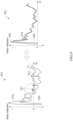
- FIG. 9 illustrates an example of determining a discharging difference threshold.
- a direction in which a voltage is reduced by a short circuit and a direction in which a voltage is reduced by aging are the same. Thus, it may not identify the short circuit and the aging using a change in a sign of a state indicator. In such a case, a short circuit may be detected using a discharging difference threshold associated with a difference indicator between discharging cycles.
- the discharging difference threshold may be set in consideration of a short circuit and/or aging.
- graph 901 indicates a first state indicator 910 obtained from a first experimental discharging cycle of a normal state and a second state indicator 920 obtained from a second experimental discharging cycle of a short circuit state.
- These discharging cycles may correspond to a pre-experiment, and a second charging cycle may proceed in a situation in which a desired short circuit condition is simulated through a simulating device such as a resistor.
- a simulating device such as a resistor.
- a battery of a smartphone may be discharged mostly under such a low rate discharging condition, and thus an experiment may be performed based on a discharging pattern in the actual use of the smartphone.
- a short circuit threshold may be determined based on a maximum difference value 932 among various difference values (e.g., difference values 931 and 932) between the first state indicator 910 and the second state indicator 920.
- a difference threshold used in a discharging process may be referred to herein as a discharging difference threshold.
- the difference threshold may be set for each discharging interval or for an entire discharging interval.
- a short circuit difference threshold may be set to be the discharging difference threshold, or an aging difference threshold may be additionally applied to the short circuit difference threshold, and the discharging difference threshold may be thereby set.
- graph 902 indicates a third state indicator 950 obtained from a third experimental discharging cycle of the normal state and a fourth state indicator 960 obtained from a fourth experimental discharging cycle of an aging state.
- a difference value 971 may correspond to a maximum aging difference between the third state indicator 950 and the fourth state indicator 960. Based on the difference value 971, the aging difference threshold may be determined.
- the short circuit difference threshold may be set to be greater than the aging difference threshold.
- a value of the short circuit difference threshold may increase by reducing a cycle interval for checking the aging state and thereby decreasing a value of the aging difference threshold, or by adjusting a magnitude of a detectable minimum short circuit to be greater.
- the short circuit difference threshold may be set to be the discharging difference threshold.
- a short circuit detection apparatus may determine that there is a short circuit in a current discharging cycle.
- FIG. 10 illustrates an example of detecting a short circuit in a charging process.
- a short circuit detection apparatus obtains a state indicator SI n .
- n has a value from 1 to N and corresponds to one timestep, and N indicates the number of all timesteps.
- the short circuit detection apparatus compares the state indicator SI n to confidence thresholds SI err+ and SI err- .
- the short circuit detection apparatus verifies whether an aging correction is available.
- the state indicator SI n is in a confidence interval between the positive confidence threshold SI err+ and the negative confidence threshold SI err- , and the aging correction is verified to be available, operation 1004 is then performed.
- the short circuit detection apparatus compares the state indicator SI n to an aging threshold SI max+ .
- the short circuit detection apparatus performs the aging correction.
- the short circuit detection apparatus may increase the value of n and perform operation 1001 again with a state indicator SI n+1 with the increased value of n.
- the short circuit detection apparatus may update the state indicator SI n while maintaining the value of n to perform operation 1007.
- the short circuit detection apparatus compares the state indicator SI n to a short circuit threshold SI max- .
- the short circuit detection apparatus determines a current state to be a normal state. Subsequently, the short circuit detection apparatus may increase the value of n and perform operation 1001 again with the increased value of n.
- the short circuit detection apparatus determines the current state to be a short circuit state.
- the short circuit detection apparatus provides a notification of the short circuit state.
- the notification of the short circuit state may be provided in various ways.
- the short circuit detection apparatus may notify a user and a manufacturer of an electronic apparatus, a service provider, and the like, of the short circuit state in real-time, and/or record a result of detecting a short circuit in the electronic apparatus.
- the result of detecting a short circuit may include short circuit information associated with, for example, whether the short circuit is detected or not, a point in time at which the short circuit is detected, a time for which the short circuit is maintained, and the intensity of the short circuit.
- a detectable level of a short circuit may be an MSC, and thus the user, the manufacturer, the service provider, and the like may perform an appropriate measure for a detected short circuit at an early stage.
- the short circuit detection apparatus may detect a short circuit by comparing the state indicator SI n and the short circuit threshold SI max- while maintaining the confidence of the short circuit threshold SI max- . However, when the state indicator SI n deviates from the confidence interval in operation 1002, or when the aging correction is verified to be unavailable in operation 1003, the short circuit detection apparatus may perform operation 1006.
- the short circuit detection apparatus compares a difference indicator ⁇ SI n to a difference threshold ⁇ SI min .
- the short circuit detection apparatus may determine the difference indicator ASI n based on a difference between a state indicator SI n in a current cycle and a state indicator SI n in a previous cycle.
- the short circuit detection apparatus determines the current state to be the normal state.
- operation 1009 when the difference indicator ⁇ SI n is greater than the difference threshold ⁇ SI min , that is, when the difference indicator ⁇ SI n deviates from the difference threshold ⁇ SI min , the short circuit detection apparatus determines the current state to be the short circuit state. Subsequently, operation 1001 or 1010 may be performed as described above.
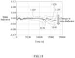
- FIG. 11 illustrates an example of a change in a state indicator.
- graph indicates directions of changes in state indicators 1110 through 1150.
- the state indicators 1110 through 1150 may indicate respective cycles based on the occurrence of a short circuit and/or aging.
- the first state indicator 1110 may indicate a first charging cycle of an aging state
- the second state indicator 1120 may indicate a second charging cycle of a normal state
- the third state indicator 1130 may indicate a third charging cycle of an aging and short circuit state
- the fourth state indicator 1140 may indicate a fourth charging cycle based on a first aging correction
- the fifth state indicator 1150 may indicate a fifth charging cycle based on a second aging correction.
- the first aging correction may remove an aging factor from the aging and short circuit state, and the fourth state indicator 1140 may thereby indicate a pattern of a short circuit state.
- the second aging correction may also remove an aging factor, and the fifth state indicator 1150 may thereby indicate a pattern of a short circuit state.
- the magnitude of the state indicators 1110 through 1150 may tend to decrease, and thus the performance of detecting a short circuit may be improved through such a tendency.
- a voltage change tendency associated with battery aging and a voltage change tendency associated with a short circuit may be opposite in the charging process, and be the same in the discharging process. Based on this, it is possible to improve the accuracy in detecting an MSC.
- aging may be over-corrected than it actually is.
- a state indicator By deriving a state indicator, an estimated value may increase, and a measured value may decrease, and thus the state indicator may decrease further than it was before the aging correction.
- aging may be reduced with an overvoltage decreasing, and the estimation model may be corrected, for example, a cell is restored.
- the estimated value may increase, and the measured value may drop compared to a normal state due to the short circuit.
- a decrease in the state indicator when there is a short circuit may be intensified than it was before the aging correction.
- the decrease in the state indicator is intensified, it may deviate from a short circuit threshold even with a finer short circuit, and thus the magnitude of a detectable short circuit may be smaller, thereby improving the performance of the detection.
- FIG. 12 illustrates an example of a short circuit detection method.
- a short circuit detection apparatus obtains battery data associated with a state of a battery from a charging cycle in operation 1210, estimates an error in the battery data using an estimation model in operation 1220, determines a state indicator corresponding to the error in the battery data in operation 1230, and detects a short circuit of the battery based on a result of comparing the state indicator and a short circuit threshold in operation 1240.
- FIGS. 1 through 11 , 13 , and 14 are also applicable to the short circuit detection method described above with reference to FIG. 12 .
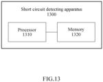
- FIG. 13 illustrates an example of a short circuit detection apparatus.
- a short circuit detection apparatus 1300 includes a processor 1310 and a memory 1320.
- the memory 1320 may be connected to the processor 1310, and store instructions executable by the processor 1310, data to be processed by the processor 1310, or data processed by the processor 1310.
- the memory 1320 may include a non-transitory computer-readable medium, for example, a high-speed random-access memory (RAM) and/or nonvolatile computer-readable storage medium (e.g., one or more disk storage devices, flash memory devices, or other nonvolatile solid-state memory devices).
- RAM high-speed random-access memory
- nonvolatile computer-readable storage medium e.g., one or more disk storage devices, flash memory devices, or other nonvolatile solid-state memory devices.
- the processor 1310 may execute instructions to perform one or more, or all, of the operations or methods described with reference to FIGS. 1 through 12 and 14 .
- the processor 1310 may obtain battery data associated with a state of a battery from a charging cycle, estimate an error in the battery data using an estimation model, determine a state indicator corresponding to the error in the battery data, and detect a short circuit of the battery based on a result of comparing the state indicator and a short circuit threshold.
- FIGS. 1 through 12 and 14 is also applicable to the detailed description of the short circuit detection apparatus 1300.
- FIG. 14 illustrates an example of an electronic apparatus.
- an electronic apparatus 1400 includes a processor 1410, a memory 1420, a camera 1430, a storage device 1440, an input device 1450, an output device 1460, a network interface 1470, and a battery 1480. These foregoing components may communicate with one another through a communication bus 1490.
- the electronic apparatus 1400 may be embodied as a portion of a mobile device (e.g., a mobile phone, a smartphone, a personal digital assistant (PDA), a netbook, a tablet computer, a laptop computer, etc.), a wearable device (e.g., a smartwatch, a smart band, smart glasses, etc.), a computing device (e.g., a desktop, a server, etc.), a home appliance (e.g., a television (TV), a smart TV, a refrigerator, etc.), a security device (e.g., a door lock, etc.), and a vehicle (e.g., an autonomous vehicle, a smart vehicle, etc.), as non-limiting examples.
- the electronic apparatus 1400 may structurally and/or functionally include the short circuit detection apparatus 100 of FIG. 1 and/or the short circuit detection apparatus 1300 of FIG. 13 .
- the processor 1410 may execute a function and instructions to be executed in the electronic apparatus 1400.
- the processor 1410 may process instructions stored in the memory 1420 or the storage device 1440.
- the processor 1410 may perform the operations and/or methods described above with reference to FIGS. 1 through 13 .
- the memory 1420 may include a computer-readable storage medium or a computer-readable storage device.
- the memory 1420 may store instructions to be executed by the processor 1410, and related information while software and/or an application is being executed by the electronic apparatus 1400.
- the camera 1430 may capture an image, for example, a still image and/or a video.
- the camera 1430 may capture a facial image, including a face of a user.
- the camera 1430 may be a three-dimensional (3D) camera, including depth information associated with objects.
- the storage device 1440 may include a computer-readable storage medium or a computer-readable storage device.
- the storage device 1440 may store a greater amount of information than the memory 1420, and store the information for a relatively long period of time.
- the storage device 1440 may include, for example, a magnetic hard disk, an optical disc, a flash memory, a floppy disk, or a nonvolatile memory of another form that is known in the related technical field.
- the input device 1450 may receive an input from a user through a traditional input method using a keyboard and a mouse, or through a new input method using a touch input, a voice input, and an image input, as non-limiting examples.
- the input device 1450 may include, for example, a keyboard, a mouse, a touchscreen, a microphone, or other devices that detect an input from a user and transfer the detected input to the electronic apparatus 1400.
- the output device 1460 may provide an output of the electronic apparatus 1400 to a user through a visual, auditory, or tactile (or haptic) channel.
- the output device 1460 may include, for example, a display, a touchscreen, a speaker, a vibration generating device, or other devices that provide an output to a user.
- the network interface 1470 may communicate with an external device through a wired or wireless network.
- the battery 1480 may store power and provide the stored power to the electronic apparatus 1400.
- the short circuit detection apparatus, the electronic apparatus, and other apparatuses, devices, units, modules, and components in FIGS. 1-14 that perform the operations described in this application are implemented by hardware components.
- hardware components that may be used to perform the operations described in this application where appropriate include controllers, sensors, generators, drivers, memories, comparators, arithmetic logic units, adders, subtractors, multipliers, dividers, integrators, and any other electronic components configured to perform the operations described in this application.
- one or more of the hardware components that perform the operations described in this application are implemented by computing hardware, for example, by one or more processors or computers.
- a processor or computer may be implemented by one or more processing elements, such as an array of logic gates, a controller and an arithmetic logic unit, a digital signal processor, a microcomputer, a programmable logic controller, a field-programmable gate array, a programmable logic array, a microprocessor, or any other device or combination of devices that is configured to respond to and execute instructions in a defined manner to achieve a desired result.
- a processor or computer includes, or is connected to, one or more memories storing instructions or software that are executed by the processor or computer.
- Hardware components implemented by a processor or computer may execute instructions or software, such as an operating system (OS) and one or more software applications that run on the OS, to perform the operations described in this application.
- OS operating system
- the hardware components may also access, manipulate, process, create, and store data in response to execution of the instructions or software.
- processor or “computer” may be used in the description of the examples described in this application, but in other examples multiple processors or computers may be used, or a processor or computer may include multiple processing elements, or multiple types of processing elements, or both.
- a single hardware component or two or more hardware components may be implemented by a single processor, or two or more processors, or a processor and a controller.
- One or more hardware components may be implemented by one or more processors, or a processor and a controller, and one or more other hardware components may be implemented by one or more other processors, or another processor and another controller.
- One or more processors may implement a single hardware component, or two or more hardware components.
- a hardware component may have any one or more of different processing configurations, examples of which include a single processor, independent processors, parallel processors, single-instruction single-data (SISD) multiprocessing, single-instruction multiple-data (SIMD) multiprocessing, multiple-instruction single-data (MISD) multiprocessing, and multiple-instruction multiple-data (MIMD) multiprocessing.
- SISD single-instruction single-data
- SIMD single-instruction multiple-data
- MIMD multiple-instruction multiple-data
- FIGS. 1-14 that perform the operations described in this application are performed by computing hardware, for example, by one or more processors or computers, implemented as described above executing instructions or software to perform the operations described in this application that are performed by the methods.
- a single operation or two or more operations may be performed by a single processor, or two or more processors, or a processor and a controller.
- One or more operations may be performed by one or more processors, or a processor and a controller, and one or more other operations may be performed by one or more other processors, or another processor and another controller.
- One or more processors, or a processor and a controller may perform a single operation, or two or more operations.
- Instructions or software to control computing hardware may be written as computer programs, code segments, instructions or any combination thereof, for individually or collectively instructing or configuring the one or more processors or computers to operate as a machine or special-purpose computer to perform the operations that are performed by the hardware components and the methods as described above.
- the instructions or software include machine code that is directly executed by the one or more processors or computers, such as machine code produced by a compiler.
- the instructions or software includes higher-level code that is executed by the one or more processors or computer using an interpreter.
- the instructions or software may be written using any programming language based on the block diagrams and the flow charts illustrated in the drawings and the corresponding descriptions in the specification, which disclose algorithms for performing the operations that are performed by the hardware components and the methods as described above.
- the instructions or software to control computing hardware for example, one or more processors or computers, to implement the hardware components and perform the methods as described above, and any associated data, data files, and data structures, may be recorded, stored, or fixed in or on one or more non-transitory computer-readable storage media.
- Examples of a non-transitory computer-readable storage medium include read-only memory (ROM), random-access programmable read only memory (PROM), electrically erasable programmable read-only memory (EEPROM), random-access memory (RAM), dynamic random access memory (DRAM), static random access memory (SRAM), flash memory, non-volatile memory, CD-ROMs, CD-Rs, CD+Rs, CD-RWs, CD+RWs, DVD-ROMs, DVD-Rs, DVD+Rs, DVD-RWs, DVD+RWs, DVD-RAMs, BD-ROMs, BD-Rs, BD-R LTHs, BD-REs, blue-ray or optical disk storage, hard disk drive (HDD), solid state drive (SSD), flash memory, a card type memory such as multimedia card micro or a card (for example, secure digital (SD) or extreme digital (XD)), magnetic tapes, floppy disks, magneto-optical data storage devices, optical data storage devices, hard disks,
- the instructions or software and any associated data, data files, and data structures are distributed over network-coupled computer systems so that the instructions and software and any associated data, data files, and data structures are stored, accessed, and executed in a distributed fashion by the one or more processors or computers.
Landscapes
- Physics & Mathematics (AREA)
- General Physics & Mathematics (AREA)
- Engineering & Computer Science (AREA)
- Power Engineering (AREA)
- Tests Of Electric Status Of Batteries (AREA)
- Charge And Discharge Circuits For Batteries Or The Like (AREA)
- Secondary Cells (AREA)
- Health & Medical Sciences (AREA)
- General Health & Medical Sciences (AREA)
- Medical Informatics (AREA)
Claims (14)
- Procédé de détection de court-circuit comprenant les opérations suivantes :obtenir (1210) des données de batterie (101) associées à l'état d'une batterie à partir d'un cycle de charge de la batterie ;estimer (1220) une erreur dans les données de la batterie (101) à l'aide d'un modèle d'estimation (110) ;déterminer (1230) un indicateur d'état (310, 320, 330, 810, 820) correspondant à l'erreur dans les données de la batterie (101) ; etdétecter (1240) un court-circuit de la batterie sur la base du résultat de la comparaison entre l'indicateur d'état (310, 320, 330, 810, 820) et un seuil de court-circuit (311, 312, 321, 331),caractérisé en ce que,en réponse à l'indicateur d'état (310, 320, 330, 810, 820) se situant hors d'une plage de confiance, la détection (1240) du court-circuit comprend les opérations suivantes :déterminer un indicateur de différence (830) fondé sur une différence entre l'indicateur d'état (310, 320, 330, 810, 820) et un indicateur d'état précédent d'un cycle de charge précédent ; etdétecter le court-circuit de la batterie fondé sur le résultat de la comparaison de l'indicateur de différence et d'un seuil de différence,l'intervalle de confiance se situe entre un seuil de confiance positif et un seuil de confiance négatif.
- Procédé selon la revendication 1, comprenant en outre
effectuer une correction du vieillissement sur la base du résultat de la comparaison entre l'indicateur d'état et un seuil de vieillissement. - Procédé selon la revendication 2, dans lequel la détection (1240) du court-circuit comprend : la comparaison d'un indicateur d'état de vieillissement, fondé sur la correction du vieillissement, au seuil de court-circuit.
- Procédé selon la revendication 2, dans lequel le signe du seuil de court-circuit est différent du signe du seuil de vieillissement.
- Procédé selon la revendication 2, dans lequel l'exécution de la correction du vieillissement comprend l'opération suivante :
mettre à jour le modèle d'estimation et l'indicateur d'état, ou l'un et l'autre, en fonction de l'état de vieillissement de la batterie. - Procédé selon la revendication 5, dans lequel l'état de vieillissement de la batterie est obtenu à partir de données mesurées.
- Procédé selon les revendications 5 ou 6, dans lequel l'état de vieillissement de la batterie est obtenu à partir de données mesurées générées par l'une ou plusieurs des procédés suivants : induction d'un court-circuit dans la batterie, simulation d'un état de court-circuit dans la batterie ou simulation d'un état de vieillissement dans la batterie.
- Procédé selon l'une des revendications 1 à 7, comprenant en outre les opérations suivantes :déterminer un indicateur d'état de décharge à partir d'un cycle de décharge de la batterie ;déterminer un indicateur de différence de décharge fondé sur une différence entre l'indicateur d'état de décharge et un indicateur d'état de décharge précédent d'un cycle de décharge précédent de la batterie ; etdétecter le court-circuit de la batterie sur la base du résultat de la comparaison entre l'indicateur de différence de décharge et un seuil de différence de décharge.
- Procédé selon l'une des revendications 1 à 8, dans lequel le seuil de court-circuit a une valeur différente dans chaque intervalle de charge du cycle de charge, et
l'intervalle de charge comprend un intervalle de courant constant (CC) et un intervalle de tension constante (CV). - Procédé selon l'une des revendications 1 à 9, dans lequel l'état de la batterie correspond à une tension de la batterie, et les données de la batterie correspondent à une valeur mesurée de la tension, et
dans lequel l'estimation de l'erreur comprend :déterminer une valeur estimée de la tension à l'aide du modèle d'estimation ; etestimer l'erreur sur la base d'une différence entre la valeur mesurée et la valeur estimée, etdans lequel le modèle d'estimation est un modèle électrochimique. - Support de stockage non transitoire lisible par ordinateur stockant des instructions qui, lorsqu'elles sont exécutées par un ou plusieurs processeurs (1410) d'un appareil de détection de court-circuit (1400) comprenant une mémoire (1420) configurée pour stocker des instructions exécutables par le ou les processeurs (1410), configurent le ou les processeurs (1410) pour :obtenir (1210) des données de batterie (101) associées à l'état d'une batterie à partir d'un cycle de charge de la batterie ;estimer (1220) une erreur dans les données de la batterie (101) à l'aide d'un modèle d'estimation (110) ;déterminer (1230) un indicateur d'état (310, 320, 330, 810, 820) correspondant à l'erreur dans les données de la batterie (101) ; etdétecter (1240) un court-circuit de la batterie sur la base du résultat de la comparaison de l'indicateur d'état (310, 320, 330, 810, 820) et d'un seuil de court-circuit (311, 312, 321, 321),dans lequel, en réponse à l'indicateur d'état (310, 320, 330, 810, 820) se situant en dehors d'une plage de confiance, les instructions configurent en outre le ou les processeurs (1410) pour détecter (1240) le court-circuit en effectuant les opérations suivantes :déterminer un indicateur de différence (830) fondé sur une différence entre l'indicateur d'état (310, 320, 330, 810, 820) et un indicateur d'état précédent d'un cycle de charge précédent ; etdétecter le court-circuit de la batterie sur la base du résultat de la comparaison entre l'indicateur de différence et un seuil de différence,l'intervalle de confiance se situe entre un seuil de confiance positif et un seuil de confiance négatif.
- Appareil électronique comprenantune batterie configurée pour fournir de l'énergie ; etun ou plusieurs processeurs (1410) configurés pour :obtenir (1210) des données de batterie (101) associées à l'état d'une batterie à partir d'un cycle de charge de la batterie ;estimer (1220) une erreur dans les données de la batterie (101) à l'aide d'un modèle d'estimation (110) ;déterminer (1230) un indicateur d'état (310, 320, 330, 810, 820) correspondant à l'erreur dans les données de la batterie (101) ; etdétecter (1240) un court-circuit de la batterie sur la base du résultat de la comparaison entre l'indicateur d'état (310, 320, 330, 810, 820) et un seuil de court-circuit (311, 312, 321, 322),caractérisé en ce que,en réponse à l'indicateur d'état (310, 320, 330, 810, 820) se situant hors d'une plage de confiance, le ou les processeurs (1410) sont en outre configurés pour détecter (1240) le court-circuit en effectuant les opérations suivantes :déterminer un indicateur de différence (830) fondé sur une différence entre l'indicateur d'état (310, 320, 330, 810, 820) et un indicateur d'état précédent d'un cycle de charge précédent ; etdétecter le court-circuit de la batterie fondé sur le résultat de la comparaison de l'indicateur de différence et d'un seuil de différence,l'intervalle de confiance se situe entre un seuil de confiance positif et un seuil de confiance négatif.
- Appareil électronique selon la revendication 12, dans lequel un ou plusieurs processeurs (1410) sont configurés pour :
effectuer une correction du vieillissement sur la base du résultat de la comparaison entre l'indicateur d'état et un seuil de vieillissement. - Appareil électronique selon la revendication 13, dans lequel le ou les processeurs (1410) sont configurés pour comparer un indicateur d'état de vieillissement, fondé sur la correction du vieillissement, au seuil de court-circuit, ou
dans lequel le signe du seuil de court-circuit est différent du signe du seuil de vieillissement.
Applications Claiming Priority (1)
| Application Number | Priority Date | Filing Date | Title |
|---|---|---|---|
| KR1020200180676A KR102892907B1 (ko) | 2020-12-22 | 2020-12-22 | 배터리의 단락 검출 장치 및 방법 |
Publications (2)
| Publication Number | Publication Date |
|---|---|
| EP4019993A1 EP4019993A1 (fr) | 2022-06-29 |
| EP4019993B1 true EP4019993B1 (fr) | 2024-06-26 |
Family
ID=76958796
Family Applications (1)
| Application Number | Title | Priority Date | Filing Date |
|---|---|---|---|
| EP21186088.7A Active EP4019993B1 (fr) | 2020-12-22 | 2021-07-16 | Procédé et appareil de détection de court-circuit de batterie |
Country Status (5)
| Country | Link |
|---|---|
| US (1) | US12136841B2 (fr) |
| EP (1) | EP4019993B1 (fr) |
| KR (1) | KR102892907B1 (fr) |
| CN (1) | CN114660476A (fr) |
| HU (1) | HUE068488T2 (fr) |
Families Citing this family (7)
| Publication number | Priority date | Publication date | Assignee | Title |
|---|---|---|---|---|
| KR102871577B1 (ko) * | 2019-09-04 | 2025-10-17 | 삼성전자주식회사 | 배터리 충전 장치 및 방법 |
| US20220200295A1 (en) * | 2020-12-23 | 2022-06-23 | Medtronic, Inc. | Systems and method for charging batteries |
| DE102021214161A1 (de) * | 2021-12-10 | 2023-06-15 | Robert Bosch Gesellschaft mit beschränkter Haftung | Verfahren und Vorrichtung zum Bereitstellen eines Alterungszustands für eine Gerätebatterie mit Korrektur von Zustandsbeobachtungen auf Basis systematischer Zustands- und Umgebungseinflüsse |
| KR102862044B1 (ko) | 2021-12-15 | 2025-09-19 | 삼성전자주식회사 | 배터리의 내부 단락을 검출하는 방법 및 장치 |
| KR102887115B1 (ko) | 2021-12-20 | 2025-11-18 | 삼성전자주식회사 | 배터리의 단락 검출 장치 및 방법 |
| KR20240101185A (ko) * | 2022-12-23 | 2024-07-02 | 주식회사 엘지에너지솔루션 | 배터리의 내부 단락 진단 방법 및 그 방법을 제공하는 배터리 시스템 |
| CN116794542B (zh) * | 2023-06-06 | 2024-01-16 | 东莞市腾威动力新能源有限公司 | 一种储能电池短路检测和保护的方法及系统 |
Family Cites Families (23)
| Publication number | Priority date | Publication date | Assignee | Title |
|---|---|---|---|---|
| TW535308B (en) | 2000-05-23 | 2003-06-01 | Canon Kk | Detecting method for detecting internal state of a rechargeable battery, detecting device for practicing said detecting method, and instrument provided with said |
| JP2008097857A (ja) | 2006-10-06 | 2008-04-24 | Matsushita Electric Ind Co Ltd | 非水電解液二次電池の製造方法 |
| JP2009049005A (ja) | 2007-07-26 | 2009-03-05 | Panasonic Corp | 電池の内部短絡検知装置および方法、電池パック並びに電子機器システム |
| US9157964B2 (en) | 2009-09-24 | 2015-10-13 | Toyota Jidosha Kabushiki Kaisha | Method for producing secondary battery |
| JP5786324B2 (ja) * | 2010-11-17 | 2015-09-30 | 日産自動車株式会社 | 組電池の制御装置 |
| US9177466B2 (en) | 2011-01-20 | 2015-11-03 | Indiana University Research And Technology Corporation | Advanced battery early warning and monitoring system |
| JP6285445B2 (ja) | 2013-08-30 | 2018-02-28 | 日本碍子株式会社 | 二次電池システムの異常発生部位を特定する装置及び方法 |
| JP5929865B2 (ja) | 2013-10-02 | 2016-06-08 | トヨタ自動車株式会社 | 二次電池の製造方法 |
| IL239852A (en) | 2015-07-08 | 2016-12-29 | Algolion Ltd | Lithium-ion battery safety monitoring |
| CN107870301B (zh) | 2016-09-27 | 2020-09-04 | 华为技术有限公司 | 一种电池微短路的检测方法及装置 |
| CN108241102A (zh) * | 2016-12-23 | 2018-07-03 | 华为技术有限公司 | 一种电池微短路的检测方法及装置 |
| US10788536B2 (en) * | 2017-05-11 | 2020-09-29 | Texas Instruments Incorporated | System and apparatus for battery internal short current detection under arbitrary load conditions |
| KR101930647B1 (ko) | 2017-11-22 | 2019-03-11 | 주식회사 포스코아이씨티 | 배터리 내부단락 진단장치 및 방법 |
| TWI649573B (zh) | 2017-12-04 | 2019-02-01 | 財團法人工業技術研究院 | 電池內短路阻抗之偵測方法和系統 |
| US10948544B2 (en) * | 2018-03-08 | 2021-03-16 | Industrial Technology Research Institute | Battery safety identifying method and method for setting hazard levels of battery internal short circuit and warning system using the same |
| KR102266591B1 (ko) * | 2018-07-23 | 2021-06-18 | 삼성에스디아이 주식회사 | 배터리 제어 장치 및 배터리의 내부단락 검출 방법 |
| US11035904B2 (en) | 2018-07-23 | 2021-06-15 | Samsung Sdi Co., Ltd. | Battery control apparatus and method for detecting internal short of battery |
| US11041914B2 (en) | 2018-08-13 | 2021-06-22 | Samsung Sdi Co., Ltd. | Battery control apparatus and method for detection internal short of battery |
| KR102079875B1 (ko) | 2018-10-10 | 2020-02-19 | 한국전력공사 | 배터리의 열화 모듈 또는 열화 셀 검출장치 및 방법 |
| JP6609687B1 (ja) * | 2018-12-27 | 2019-11-20 | 日本たばこ産業株式会社 | エアロゾル吸引器用の電源ユニット、その制御方法及び制御プログラム |
| KR102802132B1 (ko) * | 2019-02-20 | 2025-04-28 | 삼성에스디아이 주식회사 | 배터리 제어 장치 및 배터리 제어 방법 |
| KR102094359B1 (ko) * | 2019-12-10 | 2020-03-27 | 경북대학교 산학협력단 | 배터리의 열화 모델에 따라 배터리의 상태를 추정하는 배터리 상태 추정 장치 및 방법 |
| JP7244456B2 (ja) * | 2020-04-28 | 2023-03-22 | プライムアースEvエナジー株式会社 | 二次電池の状態判定方法及び二次電池の状態判定装置 |
-
2020
- 2020-12-22 KR KR1020200180676A patent/KR102892907B1/ko active Active
-
2021
- 2021-06-08 US US17/341,561 patent/US12136841B2/en active Active
- 2021-06-10 CN CN202110647838.XA patent/CN114660476A/zh active Pending
- 2021-07-16 HU HUE21186088A patent/HUE068488T2/hu unknown
- 2021-07-16 EP EP21186088.7A patent/EP4019993B1/fr active Active
Also Published As
| Publication number | Publication date |
|---|---|
| US12136841B2 (en) | 2024-11-05 |
| US20220200293A1 (en) | 2022-06-23 |
| HUE068488T2 (hu) | 2025-01-28 |
| KR102892907B1 (ko) | 2025-12-01 |
| EP4019993A1 (fr) | 2022-06-29 |
| CN114660476A (zh) | 2022-06-24 |
| KR20220089969A (ko) | 2022-06-29 |
Similar Documents
| Publication | Publication Date | Title |
|---|---|---|
| EP4019993B1 (fr) | Procédé et appareil de détection de court-circuit de batterie | |
| EP4148443B1 (fr) | Dispositif électronique et procédé d'estimation d'état de batterie | |
| US10940761B2 (en) | Battery management method and apparatus | |
| US11929468B2 (en) | Method and apparatus for charging battery | |
| EP3506452B1 (fr) | Procédé et appareil de charge de batterie | |
| EP3961232B1 (fr) | Procédé et appareil pour l'estimation de l'état d'une batterie | |
| US10627452B2 (en) | Apparatus and method for state of charge (SOC) determination for battery | |
| US11959968B2 (en) | Method and system with battery management | |
| EP3331124A1 (fr) | Procédé de chargement de batterie, procédé de génération d'informations de chargement de batterie et appareil de chargement de batterie | |
| US11680987B2 (en) | Method and apparatus with battery management | |
| EP4198539B1 (fr) | Procédé et appareil de détection de court-circuit de batterie | |
| US12228615B2 (en) | Electronic device for estimating battery state and operating method thereof | |
| EP4016100B1 (fr) | Procédé et appareil d'optimisation de batterie | |
| EP4293373B1 (fr) | Procédé et appareil de détection de court-circuit de batterie | |
| EP4053572A1 (fr) | Procédé et appareil d'estimation de l'état d'une batterie | |
| US20240426934A1 (en) | Electronic apparatus and method with battery state estimation | |
| US12381409B2 (en) | Method and device with charging control | |
| EP4160235B1 (fr) | Procédé et dispositif d'optimisation de modèle de batterie |
Legal Events
| Date | Code | Title | Description |
|---|---|---|---|
| PUAI | Public reference made under article 153(3) epc to a published international application that has entered the european phase |
Free format text: ORIGINAL CODE: 0009012 |
|
| STAA | Information on the status of an ep patent application or granted ep patent |
Free format text: STATUS: THE APPLICATION HAS BEEN PUBLISHED |
|
| STAA | Information on the status of an ep patent application or granted ep patent |
Free format text: STATUS: REQUEST FOR EXAMINATION WAS MADE |
|
| AK | Designated contracting states |
Kind code of ref document: A1 Designated state(s): AL AT BE BG CH CY CZ DE DK EE ES FI FR GB GR HR HU IE IS IT LI LT LU LV MC MK MT NL NO PL PT RO RS SE SI SK SM TR |
|
| 17P | Request for examination filed |
Effective date: 20220614 |
|
| RBV | Designated contracting states (corrected) |
Designated state(s): AL AT BE BG CH CY CZ DE DK EE ES FI FR GB GR HR HU IE IS IT LI LT LU LV MC MK MT NL NO PL PT RO RS SE SI SK SM TR |
|
| P01 | Opt-out of the competence of the unified patent court (upc) registered |
Effective date: 20230520 |
|
| GRAP | Despatch of communication of intention to grant a patent |
Free format text: ORIGINAL CODE: EPIDOSNIGR1 |
|
| STAA | Information on the status of an ep patent application or granted ep patent |
Free format text: STATUS: GRANT OF PATENT IS INTENDED |
|
| INTG | Intention to grant announced |
Effective date: 20240208 |
|
| GRAS | Grant fee paid |
Free format text: ORIGINAL CODE: EPIDOSNIGR3 |
|
| GRAA | (expected) grant |
Free format text: ORIGINAL CODE: 0009210 |
|
| STAA | Information on the status of an ep patent application or granted ep patent |
Free format text: STATUS: THE PATENT HAS BEEN GRANTED |
|
| AK | Designated contracting states |
Kind code of ref document: B1 Designated state(s): AL AT BE BG CH CY CZ DE DK EE ES FI FR GB GR HR HU IE IS IT LI LT LU LV MC MK MT NL NO PL PT RO RS SE SI SK SM TR |
|
| REG | Reference to a national code |
Ref country code: GB Ref legal event code: FG4D |
|
| REG | Reference to a national code |
Ref country code: CH Ref legal event code: EP |
|
| REG | Reference to a national code |
Ref country code: DE Ref legal event code: R096 Ref document number: 602021014728 Country of ref document: DE |
|
| PG25 | Lapsed in a contracting state [announced via postgrant information from national office to epo] |
Ref country code: BG Free format text: LAPSE BECAUSE OF FAILURE TO SUBMIT A TRANSLATION OF THE DESCRIPTION OR TO PAY THE FEE WITHIN THE PRESCRIBED TIME-LIMIT Effective date: 20240626 |
|
| PG25 | Lapsed in a contracting state [announced via postgrant information from national office to epo] |
Ref country code: FI Free format text: LAPSE BECAUSE OF FAILURE TO SUBMIT A TRANSLATION OF THE DESCRIPTION OR TO PAY THE FEE WITHIN THE PRESCRIBED TIME-LIMIT Effective date: 20240626 Ref country code: HR Free format text: LAPSE BECAUSE OF FAILURE TO SUBMIT A TRANSLATION OF THE DESCRIPTION OR TO PAY THE FEE WITHIN THE PRESCRIBED TIME-LIMIT Effective date: 20240626 |
|
| REG | Reference to a national code |
Ref country code: LT Ref legal event code: MG9D |
|
| PG25 | Lapsed in a contracting state [announced via postgrant information from national office to epo] |
Ref country code: GR Free format text: LAPSE BECAUSE OF FAILURE TO SUBMIT A TRANSLATION OF THE DESCRIPTION OR TO PAY THE FEE WITHIN THE PRESCRIBED TIME-LIMIT Effective date: 20240927 |
|
| PG25 | Lapsed in a contracting state [announced via postgrant information from national office to epo] |
Ref country code: LV Free format text: LAPSE BECAUSE OF FAILURE TO SUBMIT A TRANSLATION OF THE DESCRIPTION OR TO PAY THE FEE WITHIN THE PRESCRIBED TIME-LIMIT Effective date: 20240626 |
|
| REG | Reference to a national code |
Ref country code: NL Ref legal event code: MP Effective date: 20240626 |
|
| PG25 | Lapsed in a contracting state [announced via postgrant information from national office to epo] |
Ref country code: NO Free format text: LAPSE BECAUSE OF FAILURE TO SUBMIT A TRANSLATION OF THE DESCRIPTION OR TO PAY THE FEE WITHIN THE PRESCRIBED TIME-LIMIT Effective date: 20240926 Ref country code: LV Free format text: LAPSE BECAUSE OF FAILURE TO SUBMIT A TRANSLATION OF THE DESCRIPTION OR TO PAY THE FEE WITHIN THE PRESCRIBED TIME-LIMIT Effective date: 20240626 Ref country code: HR Free format text: LAPSE BECAUSE OF FAILURE TO SUBMIT A TRANSLATION OF THE DESCRIPTION OR TO PAY THE FEE WITHIN THE PRESCRIBED TIME-LIMIT Effective date: 20240626 Ref country code: GR Free format text: LAPSE BECAUSE OF FAILURE TO SUBMIT A TRANSLATION OF THE DESCRIPTION OR TO PAY THE FEE WITHIN THE PRESCRIBED TIME-LIMIT Effective date: 20240927 Ref country code: FI Free format text: LAPSE BECAUSE OF FAILURE TO SUBMIT A TRANSLATION OF THE DESCRIPTION OR TO PAY THE FEE WITHIN THE PRESCRIBED TIME-LIMIT Effective date: 20240626 Ref country code: BG Free format text: LAPSE BECAUSE OF FAILURE TO SUBMIT A TRANSLATION OF THE DESCRIPTION OR TO PAY THE FEE WITHIN THE PRESCRIBED TIME-LIMIT Effective date: 20240626 Ref country code: RS Free format text: LAPSE BECAUSE OF FAILURE TO SUBMIT A TRANSLATION OF THE DESCRIPTION OR TO PAY THE FEE WITHIN THE PRESCRIBED TIME-LIMIT Effective date: 20240926 |
|
| PG25 | Lapsed in a contracting state [announced via postgrant information from national office to epo] |
Ref country code: NL Free format text: LAPSE BECAUSE OF FAILURE TO SUBMIT A TRANSLATION OF THE DESCRIPTION OR TO PAY THE FEE WITHIN THE PRESCRIBED TIME-LIMIT Effective date: 20240626 |
|
| REG | Reference to a national code |
Ref country code: AT Ref legal event code: MK05 Ref document number: 1698137 Country of ref document: AT Kind code of ref document: T Effective date: 20240626 |
|
| PG25 | Lapsed in a contracting state [announced via postgrant information from national office to epo] |
Ref country code: NL Free format text: LAPSE BECAUSE OF FAILURE TO SUBMIT A TRANSLATION OF THE DESCRIPTION OR TO PAY THE FEE WITHIN THE PRESCRIBED TIME-LIMIT Effective date: 20240626 |
|
| PG25 | Lapsed in a contracting state [announced via postgrant information from national office to epo] |
Ref country code: PT Free format text: LAPSE BECAUSE OF FAILURE TO SUBMIT A TRANSLATION OF THE DESCRIPTION OR TO PAY THE FEE WITHIN THE PRESCRIBED TIME-LIMIT Effective date: 20241028 |
|
| PG25 | Lapsed in a contracting state [announced via postgrant information from national office to epo] |
Ref country code: PT Free format text: LAPSE BECAUSE OF FAILURE TO SUBMIT A TRANSLATION OF THE DESCRIPTION OR TO PAY THE FEE WITHIN THE PRESCRIBED TIME-LIMIT Effective date: 20241028 |
|
| PG25 | Lapsed in a contracting state [announced via postgrant information from national office to epo] |
Ref country code: PL Free format text: LAPSE BECAUSE OF FAILURE TO SUBMIT A TRANSLATION OF THE DESCRIPTION OR TO PAY THE FEE WITHIN THE PRESCRIBED TIME-LIMIT Effective date: 20240626 |
|
| PG25 | Lapsed in a contracting state [announced via postgrant information from national office to epo] |
Ref country code: EE Free format text: LAPSE BECAUSE OF FAILURE TO SUBMIT A TRANSLATION OF THE DESCRIPTION OR TO PAY THE FEE WITHIN THE PRESCRIBED TIME-LIMIT Effective date: 20240626 |
|
| PG25 | Lapsed in a contracting state [announced via postgrant information from national office to epo] |
Ref country code: IS Free format text: LAPSE BECAUSE OF FAILURE TO SUBMIT A TRANSLATION OF THE DESCRIPTION OR TO PAY THE FEE WITHIN THE PRESCRIBED TIME-LIMIT Effective date: 20241026 Ref country code: AT Free format text: LAPSE BECAUSE OF FAILURE TO SUBMIT A TRANSLATION OF THE DESCRIPTION OR TO PAY THE FEE WITHIN THE PRESCRIBED TIME-LIMIT Effective date: 20240626 |
|
| PG25 | Lapsed in a contracting state [announced via postgrant information from national office to epo] |
Ref country code: CZ Free format text: LAPSE BECAUSE OF FAILURE TO SUBMIT A TRANSLATION OF THE DESCRIPTION OR TO PAY THE FEE WITHIN THE PRESCRIBED TIME-LIMIT Effective date: 20240626 |
|
| PG25 | Lapsed in a contracting state [announced via postgrant information from national office to epo] |
Ref country code: SK Free format text: LAPSE BECAUSE OF FAILURE TO SUBMIT A TRANSLATION OF THE DESCRIPTION OR TO PAY THE FEE WITHIN THE PRESCRIBED TIME-LIMIT Effective date: 20240626 Ref country code: RO Free format text: LAPSE BECAUSE OF FAILURE TO SUBMIT A TRANSLATION OF THE DESCRIPTION OR TO PAY THE FEE WITHIN THE PRESCRIBED TIME-LIMIT Effective date: 20240626 |
|
| PG25 | Lapsed in a contracting state [announced via postgrant information from national office to epo] |
Ref country code: SM Free format text: LAPSE BECAUSE OF FAILURE TO SUBMIT A TRANSLATION OF THE DESCRIPTION OR TO PAY THE FEE WITHIN THE PRESCRIBED TIME-LIMIT Effective date: 20240626 Ref country code: ES Free format text: LAPSE BECAUSE OF FAILURE TO SUBMIT A TRANSLATION OF THE DESCRIPTION OR TO PAY THE FEE WITHIN THE PRESCRIBED TIME-LIMIT Effective date: 20240626 |
|
| REG | Reference to a national code |
Ref country code: HU Ref legal event code: AG4A Ref document number: E068488 Country of ref document: HU |
|
| PG25 | Lapsed in a contracting state [announced via postgrant information from national office to epo] |
Ref country code: SM Free format text: LAPSE BECAUSE OF FAILURE TO SUBMIT A TRANSLATION OF THE DESCRIPTION OR TO PAY THE FEE WITHIN THE PRESCRIBED TIME-LIMIT Effective date: 20240626 Ref country code: SK Free format text: LAPSE BECAUSE OF FAILURE TO SUBMIT A TRANSLATION OF THE DESCRIPTION OR TO PAY THE FEE WITHIN THE PRESCRIBED TIME-LIMIT Effective date: 20240626 Ref country code: RO Free format text: LAPSE BECAUSE OF FAILURE TO SUBMIT A TRANSLATION OF THE DESCRIPTION OR TO PAY THE FEE WITHIN THE PRESCRIBED TIME-LIMIT Effective date: 20240626 Ref country code: PL Free format text: LAPSE BECAUSE OF FAILURE TO SUBMIT A TRANSLATION OF THE DESCRIPTION OR TO PAY THE FEE WITHIN THE PRESCRIBED TIME-LIMIT Effective date: 20240626 Ref country code: IS Free format text: LAPSE BECAUSE OF FAILURE TO SUBMIT A TRANSLATION OF THE DESCRIPTION OR TO PAY THE FEE WITHIN THE PRESCRIBED TIME-LIMIT Effective date: 20241026 Ref country code: ES Free format text: LAPSE BECAUSE OF FAILURE TO SUBMIT A TRANSLATION OF THE DESCRIPTION OR TO PAY THE FEE WITHIN THE PRESCRIBED TIME-LIMIT Effective date: 20240626 Ref country code: EE Free format text: LAPSE BECAUSE OF FAILURE TO SUBMIT A TRANSLATION OF THE DESCRIPTION OR TO PAY THE FEE WITHIN THE PRESCRIBED TIME-LIMIT Effective date: 20240626 Ref country code: CZ Free format text: LAPSE BECAUSE OF FAILURE TO SUBMIT A TRANSLATION OF THE DESCRIPTION OR TO PAY THE FEE WITHIN THE PRESCRIBED TIME-LIMIT Effective date: 20240626 Ref country code: AT Free format text: LAPSE BECAUSE OF FAILURE TO SUBMIT A TRANSLATION OF THE DESCRIPTION OR TO PAY THE FEE WITHIN THE PRESCRIBED TIME-LIMIT Effective date: 20240626 |
|
| PG25 | Lapsed in a contracting state [announced via postgrant information from national office to epo] |
Ref country code: IT Free format text: LAPSE BECAUSE OF FAILURE TO SUBMIT A TRANSLATION OF THE DESCRIPTION OR TO PAY THE FEE WITHIN THE PRESCRIBED TIME-LIMIT Effective date: 20240626 |
|
| REG | Reference to a national code |
Ref country code: CH Ref legal event code: PL |
|
| PG25 | Lapsed in a contracting state [announced via postgrant information from national office to epo] |
Ref country code: LU Free format text: LAPSE BECAUSE OF NON-PAYMENT OF DUE FEES Effective date: 20240716 |
|
| PG25 | Lapsed in a contracting state [announced via postgrant information from national office to epo] |
Ref country code: MC Free format text: LAPSE BECAUSE OF FAILURE TO SUBMIT A TRANSLATION OF THE DESCRIPTION OR TO PAY THE FEE WITHIN THE PRESCRIBED TIME-LIMIT Effective date: 20240626 |
|
| REG | Reference to a national code |
Ref country code: DE Ref legal event code: R097 Ref document number: 602021014728 Country of ref document: DE |
|
| PG25 | Lapsed in a contracting state [announced via postgrant information from national office to epo] |
Ref country code: MC Free format text: LAPSE BECAUSE OF FAILURE TO SUBMIT A TRANSLATION OF THE DESCRIPTION OR TO PAY THE FEE WITHIN THE PRESCRIBED TIME-LIMIT Effective date: 20240626 Ref country code: LU Free format text: LAPSE BECAUSE OF NON-PAYMENT OF DUE FEES Effective date: 20240716 |
|
| PG25 | Lapsed in a contracting state [announced via postgrant information from national office to epo] |
Ref country code: DK Free format text: LAPSE BECAUSE OF FAILURE TO SUBMIT A TRANSLATION OF THE DESCRIPTION OR TO PAY THE FEE WITHIN THE PRESCRIBED TIME-LIMIT Effective date: 20240626 |
|
| PG25 | Lapsed in a contracting state [announced via postgrant information from national office to epo] |
Ref country code: CH Free format text: LAPSE BECAUSE OF NON-PAYMENT OF DUE FEES Effective date: 20240731 Ref country code: BE Free format text: LAPSE BECAUSE OF NON-PAYMENT OF DUE FEES Effective date: 20240731 |
|
| PLBE | No opposition filed within time limit |
Free format text: ORIGINAL CODE: 0009261 |
|
| STAA | Information on the status of an ep patent application or granted ep patent |
Free format text: STATUS: NO OPPOSITION FILED WITHIN TIME LIMIT |
|
| 26N | No opposition filed |
Effective date: 20250327 |
|
| REG | Reference to a national code |
Ref country code: BE Ref legal event code: MM Effective date: 20240731 |
|
| PGFP | Annual fee paid to national office [announced via postgrant information from national office to epo] |
Ref country code: GB Payment date: 20250612 Year of fee payment: 5 |
|
| PGFP | Annual fee paid to national office [announced via postgrant information from national office to epo] |
Ref country code: FR Payment date: 20250623 Year of fee payment: 5 |
|
| PG25 | Lapsed in a contracting state [announced via postgrant information from national office to epo] |
Ref country code: IE Free format text: LAPSE BECAUSE OF NON-PAYMENT OF DUE FEES Effective date: 20240716 |
|
| PGFP | Annual fee paid to national office [announced via postgrant information from national office to epo] |
Ref country code: HU Payment date: 20250711 Year of fee payment: 5 |
|
| PG25 | Lapsed in a contracting state [announced via postgrant information from national office to epo] |
Ref country code: SE Free format text: LAPSE BECAUSE OF FAILURE TO SUBMIT A TRANSLATION OF THE DESCRIPTION OR TO PAY THE FEE WITHIN THE PRESCRIBED TIME-LIMIT Effective date: 20240626 |
|
| PGFP | Annual fee paid to national office [announced via postgrant information from national office to epo] |
Ref country code: DE Payment date: 20250611 Year of fee payment: 5 |
|
| PG25 | Lapsed in a contracting state [announced via postgrant information from national office to epo] |
Ref country code: CY Free format text: LAPSE BECAUSE OF FAILURE TO SUBMIT A TRANSLATION OF THE DESCRIPTION OR TO PAY THE FEE WITHIN THE PRESCRIBED TIME-LIMIT; INVALID AB INITIO Effective date: 20210716 |