EP4020437A1 - Maschinenbox und elektronische vorrichtung - Google Patents
Maschinenbox und elektronische vorrichtung Download PDFInfo
- Publication number
- EP4020437A1 EP4020437A1 EP19933226.3A EP19933226A EP4020437A1 EP 4020437 A1 EP4020437 A1 EP 4020437A1 EP 19933226 A EP19933226 A EP 19933226A EP 4020437 A1 EP4020437 A1 EP 4020437A1
- Authority
- EP
- European Patent Office
- Prior art keywords
- case
- vents
- flow guide
- group
- fans
- Prior art date
- Legal status (The legal status is an assumption and is not a legal conclusion. Google has not performed a legal analysis and makes no representation as to the accuracy of the status listed.)
- Granted
Links
Images


Classifications
-
- G—PHYSICS
- G09—EDUCATION; CRYPTOGRAPHY; DISPLAY; ADVERTISING; SEALS
- G09F—DISPLAYING; ADVERTISING; SIGNS; LABELS OR NAME-PLATES; SEALS
- G09F9/00—Indicating arrangements for variable information in which the information is built-up on a support by selection or combination of individual elements
- G09F9/30—Indicating arrangements for variable information in which the information is built-up on a support by selection or combination of individual elements in which the desired character or characters are formed by combining individual elements
-
- G—PHYSICS
- G09—EDUCATION; CRYPTOGRAPHY; DISPLAY; ADVERTISING; SEALS
- G09F—DISPLAYING; ADVERTISING; SIGNS; LABELS OR NAME-PLATES; SEALS
- G09F19/00—Advertising or display means not otherwise provided for
- G09F19/22—Advertising or display means on roads, walls or similar surfaces, e.g. illuminated
-
- H—ELECTRICITY
- H05—ELECTRIC TECHNIQUES NOT OTHERWISE PROVIDED FOR
- H05K—PRINTED CIRCUITS; CASINGS OR CONSTRUCTIONAL DETAILS OF ELECTRIC APPARATUS; MANUFACTURE OF ASSEMBLAGES OF ELECTRICAL COMPONENTS
- H05K5/00—Casings, cabinets or drawers for electric apparatus
- H05K5/02—Details
- H05K5/0213—Venting apertures; Constructional details thereof
- H05K5/0214—Venting apertures; Constructional details thereof with means preventing penetration of rain water or dust
-
- H—ELECTRICITY
- H05—ELECTRIC TECHNIQUES NOT OTHERWISE PROVIDED FOR
- H05K—PRINTED CIRCUITS; CASINGS OR CONSTRUCTIONAL DETAILS OF ELECTRIC APPARATUS; MANUFACTURE OF ASSEMBLAGES OF ELECTRICAL COMPONENTS
- H05K7/00—Constructional details common to different types of electric apparatus
- H05K7/20—Modifications to facilitate cooling, ventilating, or heating
- H05K7/20009—Modifications to facilitate cooling, ventilating, or heating using a gaseous coolant in electronic enclosures
- H05K7/20136—Forced ventilation, e.g. by fans
- H05K7/20145—Means for directing air flow, e.g. ducts, deflectors, plenum or guides
-
- H—ELECTRICITY
- H05—ELECTRIC TECHNIQUES NOT OTHERWISE PROVIDED FOR
- H05K—PRINTED CIRCUITS; CASINGS OR CONSTRUCTIONAL DETAILS OF ELECTRIC APPARATUS; MANUFACTURE OF ASSEMBLAGES OF ELECTRICAL COMPONENTS
- H05K7/00—Constructional details common to different types of electric apparatus
- H05K7/20—Modifications to facilitate cooling, ventilating, or heating
- H05K7/20009—Modifications to facilitate cooling, ventilating, or heating using a gaseous coolant in electronic enclosures
- H05K7/20136—Forced ventilation, e.g. by fans
- H05K7/20154—Heat dissipaters coupled to components
-
- H—ELECTRICITY
- H05—ELECTRIC TECHNIQUES NOT OTHERWISE PROVIDED FOR
- H05K—PRINTED CIRCUITS; CASINGS OR CONSTRUCTIONAL DETAILS OF ELECTRIC APPARATUS; MANUFACTURE OF ASSEMBLAGES OF ELECTRICAL COMPONENTS
- H05K7/00—Constructional details common to different types of electric apparatus
- H05K7/20—Modifications to facilitate cooling, ventilating, or heating
- H05K7/20954—Modifications to facilitate cooling, ventilating, or heating for display panels
- H05K7/20972—Forced ventilation, e.g. on heat dissipaters coupled to components
Definitions
- the present disclosure relates to the field of an electronic device, and particularly, to a case and an electronic device.
- the application discloses a case and an electronic device, and aims to simultaneously improve waterproof and heat dissipation effects of the electronic device.
- a case includes:
- the case body is a cuboid and includes a front side, a rear side, an top side, a bottom side, a left side and a right side;
- vents include a first group of vents and a second group of vents;
- the front frame further includes a left border and a right border;
- water outlets are respectively formed at one end of the bottom side close to the left side, and at one end of the bottom side close to the right side; the water outlet at one end close to the left side is at the left flow guide interlayer and configured to discharge water in the left flow guide interlayer; and the water outlet at one end close to the right side is at the right flow guide interlayer and configured to discharge water in the right flow guide interlayer.
- the first baffle includes a first portion and a second portion
- the first portion includes one group of openings, and the one group of openings are disposed opposite to the first group of vents; and the case includes one group of first fans corresponding to the one group of openings, and each of the first fans is arranged at a corresponding opening on one side of the opening away from the upper border of the front frame, and configured to blow air to one side of the upper border through the corresponding opening.
- the case further includes two groups of connectors respectively in detachable connection with the left flow guide plate and the right flow guide plate, and the two groups of connectors are configured to be in detachable connection with two side end faces of a display module accommodated in the case body so as to respectively fix two side end faces of the display module to the left flow guide plate and the right flow guide plate.
- the case includes one group of second fans inside, and the one group of second fans are fixed to the lower border of the front frame, and is above the second group of vents and configured to blow air towards the direction of the top side along the front side.
- the case further includes a heat dissipation plate, one group of third fans and one group of fourth fans inside, the heat dissipation plate is arranged opposite to the transparent glass, the edges of both sides of the heat dissipation plate are respectively connected with the two groups of connectors, and a space for accommodating the display module is formed between the heat dissipation plate and the transparent glass; the third fans and the fourth fans are arranged on the surface of one side of the heat dissipation plate away from the transparent glass, and configured to blow air towards the direction of the top side; and the third fans are arranged close to the lower end of the heat dissipation plate, and the fourth fans are above the third fans.
- the case body includes rain shelters, positions of the rain shelters correspond to positions of the vents, and the rain shelters protrude towards a direction away from an outer side of the case body.
- An electronic device includes a display module and the case according to any one of the above, and the display module is in the case and is in detachable connection with the case.
- the case includes the second baffle, and the second baffle is right below the display module.
- the electronic device further includes a circuit board which is in the case body and configured to be electrically connected with the display module, and the circuit board is arranged on the second baffle and on one side of the second baffle away from the lower border of the front frame.
- an embodiment of the present disclosure provides a case, including:
- the vents are disposed on the case body 100, so that heat dissipation may be carried out on modules inside the case by air cooling, and heat dissipation efficiency is relatively high.
- the water retaining mechanism is arranged on the inner wall of the case body 100 and at the vents, so that rainwater through the vents may be blocked, then the rainwater is remained in the water retaining mechanism and it is avoided that the rainwater enters an electronic device accommodation space behind the water retaining mechanism, and thus, a waterproof effect of the case body 100 can be effectively improved.
- the case gives consideration to both heat dissipation and the waterproof design, and simultaneously has good heat dissipating and waterproof effects.
- the case in the application may be configured to accommodate an electronic device, is particularly applicable to an outdoor space, and exemplarily, may be used as an outdoor advertising case.
- the case body 100 is a solid, and may be a cuboid, or a cube and the like.
- the case body has six sides both inside and outside, including two opposite sides, i.e., a front side 101 and a rear side, and four sides connected with the two sides, including a top side 102, a bottom side 103, a left side 104 and a right side 105.
- descriptions such as “top side”, “bottom side” and “upper edge”, “lower edge”, “above”, “below” and the like mentioned below, refer to descriptions on relative position and functional forms of a certain structure in a state that the case body is vertically placed (for example, in a placement state of the case, configured to display outdoor advertising).
- the front side 101 of the case body 100 includes a front frame 1 and transparent glass 2 arranged on the front frame 1, and exemplarily, the transparent glass 2 may be toughened glass.
- the transparent glass 2 is configured to exhibit or display a display module 71 inside the case body 100, and the display module 71 generally directly faces the transparent glass 2; and the front frame 1 generally is made of a metal material, the transparent glass 2 may be fixed to the front frame 1 by screws, a gap between the transparent glass 2 and the front frame is sealed by an adhesive, and exemplarily, the adhesive is an AB adhesive.
- the vents are disposed on the front frame 1, and the water retaining mechanism is connected with the front frame 1 in a matching manner.
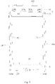
- the front frame 1 is of a rectangle shape, and includes upper, lower, left and right borders, i.e., an upper border 11, a lower border 12, a left border 13 and a right border 14 as shown in Fig. 2 .
- the vents include the first group of vents 110 and the second group of vents 120; the first group of vents 110 are disposed on the upper border 11, and the second group of vents 120 are disposed on the lower border 12; and the arrangement of both the upper and lower groups of vents is beneficial for forming air flow circulation inside and outside the case body so as to reinforce heat dissipation.
- the water retaining mechanism includes the first baffle 3; the first baffle 3 is arranged at the first group of vents 110 on the upper border 11 and connected with the upper border 11 to form a first water storage portion 30 surrounding the first group of vents 110; and the first baffle 3 may block rainwater through the first group of vents 110 and reserve the water in the first water storage portion 30 so as to avoid a case that the rainwater enters an electronic device accommodation space inside the case body.
- the water retaining mechanism may further include the second baffle 4, the second baffle 4 is arranged on the bottom side 103 and arranged opposite to the second group of vents 120 on the lower border 12, and the second baffle 4 may block rainwater from the second group of vents 120 so as to avoid the rainwater splashing into the electronic device accommodation space inside the case body.
- the second baffle 4 may block rainwater from the second group of vents 120 so as to avoid the rainwater splashing into the electronic device accommodation space inside the case body.
- the case further includes a left flow guide plate 51 and a right flow guide plate 52, wherein the edges of the left flow guide plate 51 are respectively connected with the left border of the front frame, the left side 104, the top side 102 and the bottom side 103 so as to form a left flow guide interlayer 510; and the edges of the right flow guide plate are respectively connected with the right border 14 of the front frame, the right side 105, the top side 102 and the bottom side 103 so as to form a right flow guide interlayer 520.
- Fig. 4 and Fig. 5 show a case that the edges of the right flow guide plate 52 are respectively connected with the right border 14, the right side 105, the top side 102 and the bottom side 103 so as to form the right flow guide interlayer 520.
- an extension direction of the first baffle 3 is the same as an extension direction of the upper border of the front frame, and the edges of both ends of the first baffle 3 in the extension direction of the first baffle 3 are respectively connected with the left flow guide plate 51 and the right flow guide plate 52, so that both ends of the first water storage portion respectively communicate with the left side flow guide interlayer and the right side flow guide interlayer.
- water outlets 1030 are respectively formed at one end of the bottom side 103 close to the left side 104, and at one end of the bottom side 103 close to the right side 105; the water outlet 1030 at one end close to the left side 104 is positioned at the left side flow guide interlayer and configured to discharge water in the left side flow guide interlayer; and the water outlet 1030 at one end close to the right side 105 is positioned at the right side flow guide interlayer and configured to discharge water in the right side flow guide interlayer.
- the rainwater reserved in the first water storage portion above may be guided to the bottom side 103 through the left side flow guide interlayer and the right side flow guide interlayer and then discharged through the water outlets 1220 so as to avoid rainwater accumulation.
- the case disclosed by embodiments of the present disclosure cannot only prevent the rainwater from entering the module accommodation space by the first baffle 3 and the second baffle 4, but also guide the rainwater blocked by the first baffle 3 at the upper part to the bottom of the case and discharge the rainwater out of the case body, so that waterproofness of the overall case can be effectively improved.
- the case further includes two groups of connectors 6 respectively in detachable connection with the left flow guide plate 51 and the right flow guide plate 52, and the two groups of connectors 6 are configured to be in detachable connection with two side end faces of the display module 71 accommodated in the case body so as to respectively fix two side end faces of the display module 71 to the left flow guide plate 51 and the right flow guide plate 52.
- the second baffle 4 is positioned right below the display module 6.
- the case may further include a fan assembly, and the fan assembly is positioned in the case body and may form air flow in the case body, so that air inside and outside the case may be circulated through the first group of vents and the second group of vents, and dissipation of heat inside the case body is accelerated.
- the first baffle 3 may include a first portion 31 and a second portion 32; a main side of the first portion 31 is arranged opposite to the upper border 11 of the front frame and extends from the left side 104 to the right side 105, and the upper edge of the first portion 31 is close to the top side 102 and is connected with the top side 102, while the lower edge is connected with the upper edge of the second portion 32; the second portion 32 is inclined towards the upper border 11 relative to the first portion 31, and the lower edge of the second portion 32 is in sealed connection with the upper border 11; and further, a water storage portion, i.e., the first water storage portion 30, is formed by the first portion 31 and the second portion 32 of the first baffle 3, the upper border 11 and the top side 102 in an enclosed manner together.
- a water storage portion i.e., the first water storage portion 30
- the first portion 31 directly faces the upper border 11 and may shield the first group of vents 110 so as to avoid rainwater entering the inside cavity through the first group of vents 110, and thus, the blocked rainwater may slide to the bottom of the first water storage portion 30 along the second portion 32 and further flows to the bottom of the case from the left side flow guide interlayer and the right side flow guide interlayer.
- the first portion 31 is provided with openings 310 for allowing air circulation.
- the air flow in the module accommodation space may sequentially pass through the openings 310 and the first group of vents 110 so as to implement air circulation with the external space.
- the first portion 31 may be provided with one group of openings 310, and the one group of openings 310 are disposed opposite to the first group of vents 110.
- the case includes one group of first fans 81 corresponding to the one group of openings 310 inside, and each of the first fans 81 is arranged at the corresponding opening 310, positioned on one side of the opening 310 away from the upper border 11 of the front frame, and configured to blow air to the upper border 11 through the opening 310.
- the case further includes one group of second fans 82 inside, and the one group of second fans 82 are fixed to the lower border 12 of the front frame, positioned above the second group of vents 120 and configured to blow air towards the direction of the top side 102 along the front side of the case body.
- the display module 71 is mounted in the case body by the connectors 6, and a gap 20 is formed between a display surface of the display module 71 and the transparent glass 2; and optionally, the one group of second fans 82 may blow air into the gap 20 to take away heat between the display module 71 and the transparent glass 2, so that an excessively high temperature between the display module 71 and the transparent glass 2, which is caused by inward irradiation of outdoor sunlight through the transparent glass 2, can be effectively prevented.
- the one group of second fans 82 may blow air into the gap 20 to take away heat between the display module 71 and the transparent glass 2, so that an excessively high temperature between the display module 71 and the transparent glass 2, which is caused by inward irradiation of outdoor sunlight through the transparent glass 2, can be effectively prevented.
- the second portion 32 of the first baffle 3 is inclined towards the upper border 11 of the front frame, and the air flow may ascend along the second portion 32 to reach the first portion 31 after reaching the first baffle 3 through the gap 20, enters the first water storage portion 30 through the openings on the first portion 31 and finally, is discharged out of the case body.
- the case further includes a heat dissipation plate 85, one group of third fans 83 and one group of fourth fans 84 inside.
- the heat dissipation plate 85 is arranged opposite to the transparent glass 2, the edges of both sides of the heat dissipation plate 85 are respectively connected with the two groups of connectors 6, and a space for accommodating the display module 71 is formed between the heat dissipation plate 85 and the transparent glass 2.
- the third fans 83 and the fourth fans 84 are arranged on the surface of one side of the heat dissipation plate 85 facing away from the transparent glass 2, and configured to blow air towards the direction of the top side 102; and the one group of third fans 83 are arranged close to the lower end of the heat dissipation plate 85, and the one group of fourth fans 84 are positioned above the one group of third fans 83, i.e., one group of fourth fans 84 and one group of third fans 83 are arranged up and down and disposed side by side.
- the heat dissipation plate 85 can accelerate heat dissipation efficiency of the rear side (one side facing the rear side of the case body) of the display module 71, and the third fans 83 and the fourth fans 84 are positioned between the heat dissipation plate 85 and the rear side of the case body and may take away heat between the display module 71 and the rear side of the case so as to accelerate heat dissipation on the rear side of the display module 71.
- the third fans 83 are arranged close to the lower end of the heat dissipation plate 85; under the drive of the third fans 83, cold air through the second group of vents may bypass the second baffle 4 to reach the rear side of the display module 71; and under the further drive of the fourth fans 84, the air flow on the rear side of the display module 71 may further ascend to the position of the first baffle 3 so as to take away heat on the rear side of the display module 71, and the air flow reaching the first baffle may be discharged out of the case body through one group of first fans 81.
- the outside air enters the case body through the second group of vents 120; under the drive of the second fans 82, the third fans 83 and the fourth fans 84, the air flow flows upwards and simultaneously, takes away heat around the display module 71; and further, the air flow may enter the first water storage portion under the drive of the first fans 81 after reaching the upper portion, and is discharged out of the case body through the first group of vents.
- Such circulation not only can effectively reduce a temperature of a module product, but also can achieve the waterproof effect.
- the case body may further be provided with rain shelters 10 corresponding to the positions of the vents (for example, the first vents 110 and the second vents 120 in Fig. 1 ).
- the rain shelters 10 are positioned above the vents and protrude towards a direction away from an outer side of the case body 100, so that the rainwater entering the case through the vents can be effectively reduced, thereby improving overall waterproofness of the case body 100.
- the rain shelters 10 may correspond to the vents one to one, i.e., one rain shelter 10 is arranged above each vent.
- the rain shelters may also correspond to one group of vents, i.e., one common rain shelter is designed above one group of vents.
- the front frame of the front side, the top side 102, the bottom side 103, the left side 104 and the right side 105 of the case body may be of an integrated structure, and the integrated structure is a front cover; and the left flow guide plate 51 and the right flow guide plate 52 are separately connected to an inner side of the front cover.
- the edges of both sides of the rear side of the case body may be respectively connected to the left side flow guide plate and the right side flow guide plate by screws so as to implement fixed connection with the front cover.
- waterproof foam may also be placed at the junction of the front cover and the rear side so as to prevent the rainwater from entering the case body through an assembly gap.
- the vents and the water retaining mechanism may also be disposed on the rear side, the left side or the right side
- the water retaining structure is not limited to a flat plate and may also be an arc plate or a curved plate
- the fan assembly is also not limited to the setting of the first fans, the second fans, the third fans and the like, and specifically, many improvements or modifications can be made according to the invention purpose of the embodiments of the application.
- an embodiment of the present disclosure further provides an electronic device.
- the electronic device includes the case according to any one of the above, and a display module 71 which is positioned in the case body and is in detachable connection with the case body.
- the case body includes transparent glass 2, and a display surface of the display module 71 is opposite to the transparent glass 2.
- the case includes a first baffle 3 and a second baffle 4, and the first baffle 3 is positioned above the display module; and the second baffle 4 is positioned right below the display module.
- the electronic device disclosed by the embodiment of the present disclosure further includes a circuit board 72 which is positioned in the case body and configured to be electrically connected with the display module 71, and the circuit board 72 may include a mainboard and a control circuit board; and the circuit board 72 is arranged on the second baffle 4 and positioned on one side of the second baffle 4 away from the lower border of the front frame.
- the second baffle 4 may block the rainwater from the second group of vents so as to avoid rainwater splashing to the circuit board 72.
- the electronic device provided by the embodiment of the present disclosure simultaneously gives both consideration to waterproofness and heat dissipation, and may be used as an outdoor advertising machine.
Landscapes
- Engineering & Computer Science (AREA)
- Microelectronics & Electronic Packaging (AREA)
- Physics & Mathematics (AREA)
- Thermal Sciences (AREA)
- General Physics & Mathematics (AREA)
- Theoretical Computer Science (AREA)
- Business, Economics & Management (AREA)
- Accounting & Taxation (AREA)
- Marketing (AREA)
- Casings For Electric Apparatus (AREA)
- Devices For Indicating Variable Information By Combining Individual Elements (AREA)
- Cooling Or The Like Of Electrical Apparatus (AREA)
Applications Claiming Priority (1)
| Application Number | Priority Date | Filing Date | Title |
|---|---|---|---|
| PCT/CN2019/102320 WO2021035422A1 (zh) | 2019-08-23 | 2019-08-23 | 机箱及电子设备 |
Publications (3)
| Publication Number | Publication Date |
|---|---|
| EP4020437A1 true EP4020437A1 (de) | 2022-06-29 |
| EP4020437A4 EP4020437A4 (de) | 2022-08-31 |
| EP4020437B1 EP4020437B1 (de) | 2025-03-19 |
Family
ID=72704370
Family Applications (1)
| Application Number | Title | Priority Date | Filing Date |
|---|---|---|---|
| EP19933226.3A Active EP4020437B1 (de) | 2019-08-23 | 2019-08-23 | Maschinenbox und elektronische vorrichtung |
Country Status (4)
| Country | Link |
|---|---|
| US (1) | US11737222B2 (de) |
| EP (1) | EP4020437B1 (de) |
| CN (1) | CN211654173U (de) |
| WO (1) | WO2021035422A1 (de) |
Families Citing this family (4)
| Publication number | Priority date | Publication date | Assignee | Title |
|---|---|---|---|---|
| CN114566102B (zh) * | 2020-11-27 | 2025-03-21 | 京东方科技集团股份有限公司 | 显示装置 |
| CN115361827B (zh) * | 2022-08-19 | 2024-11-26 | 中国电子科技集团公司第五十四研究所 | 一种无线通信信号调试设备用辅助装置 |
| CN115589700B (zh) * | 2022-09-08 | 2023-06-13 | 深圳市浩鑫能源有限公司 | 一种防水的ac/dc双向电源 |
| CN118829123B (zh) * | 2024-04-03 | 2025-10-03 | 中国移动通信集团设计院有限公司 | 一种电子设备安装组件、机柜及机柜安装方法 |
Family Cites Families (17)
| Publication number | Priority date | Publication date | Assignee | Title |
|---|---|---|---|---|
| US4557095A (en) * | 1983-06-29 | 1985-12-10 | Square D Company | Vent assembly for electrical enclosure |
| US5201879A (en) * | 1991-09-18 | 1993-04-13 | S&C Electric Company | Vent for enclosures |
| US20080222932A1 (en) * | 2007-03-09 | 2008-09-18 | Peng Yun | Display cabinet for light emitting diode lights and method of use |
| JP2009296105A (ja) * | 2008-06-03 | 2009-12-17 | Sanyo Electric Co Ltd | 画像表示装置 |
| US8864560B2 (en) * | 2008-07-16 | 2014-10-21 | Commscope, Inc. Of North Carolina | Water-blocking vent panel and air filter therefor |
| EP2169654A1 (de) | 2008-09-29 | 2010-03-31 | Daktronics, Inc. | Belüftetes waschbares Gehäuse für eine elektronische Anzeigevorrictung |
| US20130171921A1 (en) | 2010-08-30 | 2013-07-04 | Sanyo Electric Co., Ltd. | Display device |
| TW201218912A (en) * | 2010-10-20 | 2012-05-01 | Delta Electronics Inc | Waterproof module and cabinet employing the same |
| US20120298330A1 (en) * | 2010-11-19 | 2012-11-29 | Purcell Systems, Inc. | Air path rain guard for a cooling system of a weatherproof enclosure for electrical equipment and the like |
| KR102063074B1 (ko) * | 2013-04-23 | 2020-01-07 | 엘지전자 주식회사 | 디지털 사이니지 |
| CN204153882U (zh) | 2014-08-06 | 2015-02-11 | 大金工业株式会社 | 空调室外机 |
| TWI623254B (zh) * | 2016-03-31 | 2018-05-01 | 揚昇照明股份有限公司 | 電子裝置 |
| CN107826032A (zh) | 2017-11-16 | 2018-03-23 | 宁波远见传媒股份有限公司 | 一种汽车车顶灯箱进风结构 |
| CN107856604A (zh) | 2017-11-16 | 2018-03-30 | 宁波远见传媒股份有限公司 | 一种汽车车顶灯箱 |
| US10299415B1 (en) | 2017-11-20 | 2019-05-21 | Litemax Electronics Inc. | Water barrier structure for display unit |
| CN108665819A (zh) | 2018-06-26 | 2018-10-16 | 嘉兴商迈电子有限公司 | 防水型户外液晶一体机 |
| CN208891110U (zh) | 2018-11-30 | 2019-05-21 | 深圳市中兴新力精密机电技术有限公司 | 一种防水机柜 |
-
2019
- 2019-08-23 WO PCT/CN2019/102320 patent/WO2021035422A1/zh not_active Ceased
- 2019-08-23 US US16/958,608 patent/US11737222B2/en active Active
- 2019-08-23 EP EP19933226.3A patent/EP4020437B1/de active Active
- 2019-08-23 CN CN201990000111.9U patent/CN211654173U/zh not_active Expired - Fee Related
Also Published As
| Publication number | Publication date |
|---|---|
| EP4020437B1 (de) | 2025-03-19 |
| EP4020437A4 (de) | 2022-08-31 |
| CN211654173U (zh) | 2020-10-09 |
| US11737222B2 (en) | 2023-08-22 |
| WO2021035422A1 (zh) | 2021-03-04 |
| US20230087511A1 (en) | 2023-03-23 |
Similar Documents
| Publication | Publication Date | Title |
|---|---|---|
| US11737222B2 (en) | Case and electronic device | |
| ES2382007T3 (es) | Inversor | |
| CN109237640B (zh) | 空调室外机和空调器 | |
| WO2018153261A1 (zh) | 管塔及基站 | |
| KR102718003B1 (ko) | 에너지 저장시스템 | |
| JP3665450B2 (ja) | 空気調和機の室外ユニット | |
| EP3124769A1 (de) | Paktespeichermotorartiger stromgenerator | |
| EP3327362B1 (de) | Ausseneinheit für klimaanlagenvorrichtung | |
| CN207491431U (zh) | 智能汇流箱的风冷散热结构 | |
| CN104837311A (zh) | 一种开关电源防雨盒 | |
| CN209930817U (zh) | 电器盒结构及具有其的空调器 | |
| CN208796610U (zh) | 一种防水散热的户外led显示屏 | |
| CN217509312U (zh) | 一种散热机柜 | |
| CN217217087U (zh) | 一种电源模块机壳 | |
| CN212870015U (zh) | 一种外壳散热结构及空调室外机 | |
| CN209283612U (zh) | 一种改良的散热型路由器 | |
| CN218732627U (zh) | 一种配电柜 | |
| CN218241249U (zh) | Led显示装置 | |
| CN223356508U (zh) | 货柜 | |
| CN219811826U (zh) | 防爆配电箱风冷降温机构 | |
| CN217902652U (zh) | 一种led屏压铸箱体 | |
| CN216528871U (zh) | 一种高散热的pir太阳能控制芯片 | |
| CN217363667U (zh) | 一种节能环保的多功能电气自动化控制设备 | |
| CN219659668U (zh) | 一种光伏组件接线盒 | |
| CN215772090U (zh) | 一种带有配电箱安装架的配电箱 |
Legal Events
| Date | Code | Title | Description |
|---|---|---|---|
| STAA | Information on the status of an ep patent application or granted ep patent |
Free format text: STATUS: UNKNOWN |
|
| STAA | Information on the status of an ep patent application or granted ep patent |
Free format text: STATUS: THE INTERNATIONAL PUBLICATION HAS BEEN MADE |
|
| PUAI | Public reference made under article 153(3) epc to a published international application that has entered the european phase |
Free format text: ORIGINAL CODE: 0009012 |
|
| STAA | Information on the status of an ep patent application or granted ep patent |
Free format text: STATUS: REQUEST FOR EXAMINATION WAS MADE |
|
| 17P | Request for examination filed |
Effective date: 20201223 |
|
| AK | Designated contracting states |
Kind code of ref document: A1 Designated state(s): AL AT BE BG CH CY CZ DE DK EE ES FI FR GB GR HR HU IE IS IT LI LT LU LV MC MK MT NL NO PL PT RO RS SE SI SK SM TR |
|
| A4 | Supplementary search report drawn up and despatched |
Effective date: 20220801 |
|
| RIC1 | Information provided on ipc code assigned before grant |
Ipc: H05K 5/02 20060101ALI20220726BHEP Ipc: G09F 19/22 20060101ALI20220726BHEP Ipc: G09F 9/30 20060101ALI20220726BHEP Ipc: H05K 7/20 20060101ALI20220726BHEP Ipc: G09F 9/33 20060101AFI20220726BHEP |
|
| DAV | Request for validation of the european patent (deleted) | ||
| DAX | Request for extension of the european patent (deleted) | ||
| GRAP | Despatch of communication of intention to grant a patent |
Free format text: ORIGINAL CODE: EPIDOSNIGR1 |
|
| STAA | Information on the status of an ep patent application or granted ep patent |
Free format text: STATUS: GRANT OF PATENT IS INTENDED |
|
| INTG | Intention to grant announced |
Effective date: 20241010 |
|
| GRAS | Grant fee paid |
Free format text: ORIGINAL CODE: EPIDOSNIGR3 |
|
| GRAA | (expected) grant |
Free format text: ORIGINAL CODE: 0009210 |
|
| STAA | Information on the status of an ep patent application or granted ep patent |
Free format text: STATUS: THE PATENT HAS BEEN GRANTED |
|
| AK | Designated contracting states |
Kind code of ref document: B1 Designated state(s): AL AT BE BG CH CY CZ DE DK EE ES FI FR GB GR HR HU IE IS IT LI LT LU LV MC MK MT NL NO PL PT RO RS SE SI SK SM TR |
|
| REG | Reference to a national code |
Ref country code: GB Ref legal event code: FG4D |
|
| REG | Reference to a national code |
Ref country code: CH Ref legal event code: EP |
|
| REG | Reference to a national code |
Ref country code: DE Ref legal event code: R096 Ref document number: 602019067638 Country of ref document: DE |
|
| REG | Reference to a national code |
Ref country code: IE Ref legal event code: FG4D |
|
| PG25 | Lapsed in a contracting state [announced via postgrant information from national office to epo] |
Ref country code: RS Free format text: LAPSE BECAUSE OF FAILURE TO SUBMIT A TRANSLATION OF THE DESCRIPTION OR TO PAY THE FEE WITHIN THE PRESCRIBED TIME-LIMIT Effective date: 20250619 |
|
| PG25 | Lapsed in a contracting state [announced via postgrant information from national office to epo] |
Ref country code: FI Free format text: LAPSE BECAUSE OF FAILURE TO SUBMIT A TRANSLATION OF THE DESCRIPTION OR TO PAY THE FEE WITHIN THE PRESCRIBED TIME-LIMIT Effective date: 20250319 |
|
| REG | Reference to a national code |
Ref country code: LT Ref legal event code: MG9D |
|
| PG25 | Lapsed in a contracting state [announced via postgrant information from national office to epo] |
Ref country code: NO Free format text: LAPSE BECAUSE OF FAILURE TO SUBMIT A TRANSLATION OF THE DESCRIPTION OR TO PAY THE FEE WITHIN THE PRESCRIBED TIME-LIMIT Effective date: 20250619 |
|
| PG25 | Lapsed in a contracting state [announced via postgrant information from national office to epo] |
Ref country code: HR Free format text: LAPSE BECAUSE OF FAILURE TO SUBMIT A TRANSLATION OF THE DESCRIPTION OR TO PAY THE FEE WITHIN THE PRESCRIBED TIME-LIMIT Effective date: 20250319 |
|
| PG25 | Lapsed in a contracting state [announced via postgrant information from national office to epo] |
Ref country code: LV Free format text: LAPSE BECAUSE OF FAILURE TO SUBMIT A TRANSLATION OF THE DESCRIPTION OR TO PAY THE FEE WITHIN THE PRESCRIBED TIME-LIMIT Effective date: 20250319 |
|
| PG25 | Lapsed in a contracting state [announced via postgrant information from national office to epo] |
Ref country code: BG Free format text: LAPSE BECAUSE OF FAILURE TO SUBMIT A TRANSLATION OF THE DESCRIPTION OR TO PAY THE FEE WITHIN THE PRESCRIBED TIME-LIMIT Effective date: 20250319 Ref country code: GR Free format text: LAPSE BECAUSE OF FAILURE TO SUBMIT A TRANSLATION OF THE DESCRIPTION OR TO PAY THE FEE WITHIN THE PRESCRIBED TIME-LIMIT Effective date: 20250620 |
|
| REG | Reference to a national code |
Ref country code: NL Ref legal event code: MP Effective date: 20250319 |
|
| REG | Reference to a national code |
Ref country code: AT Ref legal event code: MK05 Ref document number: 1777644 Country of ref document: AT Kind code of ref document: T Effective date: 20250319 |
|
| PG25 | Lapsed in a contracting state [announced via postgrant information from national office to epo] |
Ref country code: NL Free format text: LAPSE BECAUSE OF FAILURE TO SUBMIT A TRANSLATION OF THE DESCRIPTION OR TO PAY THE FEE WITHIN THE PRESCRIBED TIME-LIMIT Effective date: 20250319 |
|
| PG25 | Lapsed in a contracting state [announced via postgrant information from national office to epo] |
Ref country code: SE Free format text: LAPSE BECAUSE OF FAILURE TO SUBMIT A TRANSLATION OF THE DESCRIPTION OR TO PAY THE FEE WITHIN THE PRESCRIBED TIME-LIMIT Effective date: 20250319 |
|
| PG25 | Lapsed in a contracting state [announced via postgrant information from national office to epo] |
Ref country code: SM Free format text: LAPSE BECAUSE OF FAILURE TO SUBMIT A TRANSLATION OF THE DESCRIPTION OR TO PAY THE FEE WITHIN THE PRESCRIBED TIME-LIMIT Effective date: 20250319 |
|
| PG25 | Lapsed in a contracting state [announced via postgrant information from national office to epo] |
Ref country code: ES Free format text: LAPSE BECAUSE OF FAILURE TO SUBMIT A TRANSLATION OF THE DESCRIPTION OR TO PAY THE FEE WITHIN THE PRESCRIBED TIME-LIMIT Effective date: 20250319 Ref country code: PT Free format text: LAPSE BECAUSE OF FAILURE TO SUBMIT A TRANSLATION OF THE DESCRIPTION OR TO PAY THE FEE WITHIN THE PRESCRIBED TIME-LIMIT Effective date: 20250721 |
|
| PGFP | Annual fee paid to national office [announced via postgrant information from national office to epo] |
Ref country code: DE Payment date: 20250820 Year of fee payment: 7 |
|
| PG25 | Lapsed in a contracting state [announced via postgrant information from national office to epo] |
Ref country code: PL Free format text: LAPSE BECAUSE OF FAILURE TO SUBMIT A TRANSLATION OF THE DESCRIPTION OR TO PAY THE FEE WITHIN THE PRESCRIBED TIME-LIMIT Effective date: 20250319 Ref country code: IT Free format text: LAPSE BECAUSE OF FAILURE TO SUBMIT A TRANSLATION OF THE DESCRIPTION OR TO PAY THE FEE WITHIN THE PRESCRIBED TIME-LIMIT Effective date: 20250319 |
|
| PG25 | Lapsed in a contracting state [announced via postgrant information from national office to epo] |
Ref country code: AT Free format text: LAPSE BECAUSE OF FAILURE TO SUBMIT A TRANSLATION OF THE DESCRIPTION OR TO PAY THE FEE WITHIN THE PRESCRIBED TIME-LIMIT Effective date: 20250319 |
|
| PG25 | Lapsed in a contracting state [announced via postgrant information from national office to epo] |
Ref country code: CZ Free format text: LAPSE BECAUSE OF FAILURE TO SUBMIT A TRANSLATION OF THE DESCRIPTION OR TO PAY THE FEE WITHIN THE PRESCRIBED TIME-LIMIT Effective date: 20250319 Ref country code: EE Free format text: LAPSE BECAUSE OF FAILURE TO SUBMIT A TRANSLATION OF THE DESCRIPTION OR TO PAY THE FEE WITHIN THE PRESCRIBED TIME-LIMIT Effective date: 20250319 |
|
| PG25 | Lapsed in a contracting state [announced via postgrant information from national office to epo] |
Ref country code: RO Free format text: LAPSE BECAUSE OF FAILURE TO SUBMIT A TRANSLATION OF THE DESCRIPTION OR TO PAY THE FEE WITHIN THE PRESCRIBED TIME-LIMIT Effective date: 20250319 |
|
| PG25 | Lapsed in a contracting state [announced via postgrant information from national office to epo] |
Ref country code: SK Free format text: LAPSE BECAUSE OF FAILURE TO SUBMIT A TRANSLATION OF THE DESCRIPTION OR TO PAY THE FEE WITHIN THE PRESCRIBED TIME-LIMIT Effective date: 20250319 |
|
| PG25 | Lapsed in a contracting state [announced via postgrant information from national office to epo] |
Ref country code: IS Free format text: LAPSE BECAUSE OF FAILURE TO SUBMIT A TRANSLATION OF THE DESCRIPTION OR TO PAY THE FEE WITHIN THE PRESCRIBED TIME-LIMIT Effective date: 20250719 |
|
| REG | Reference to a national code |
Ref country code: DE Ref legal event code: R097 Ref document number: 602019067638 Country of ref document: DE |
|
| PG25 | Lapsed in a contracting state [announced via postgrant information from national office to epo] |
Ref country code: DK Free format text: LAPSE BECAUSE OF FAILURE TO SUBMIT A TRANSLATION OF THE DESCRIPTION OR TO PAY THE FEE WITHIN THE PRESCRIBED TIME-LIMIT Effective date: 20250319 |
|
| PLBE | No opposition filed within time limit |
Free format text: ORIGINAL CODE: 0009261 |
|
| STAA | Information on the status of an ep patent application or granted ep patent |
Free format text: STATUS: NO OPPOSITION FILED WITHIN TIME LIMIT |
|
| REG | Reference to a national code |
Ref country code: CH Ref legal event code: L10 Free format text: ST27 STATUS EVENT CODE: U-0-0-L10-L00 (AS PROVIDED BY THE NATIONAL OFFICE) Effective date: 20260128 |
|
| 26N | No opposition filed |
Effective date: 20251222 |
|
| REG | Reference to a national code |
Ref country code: CH Ref legal event code: H13 Free format text: ST27 STATUS EVENT CODE: U-0-0-H10-H13 (AS PROVIDED BY THE NATIONAL OFFICE) Effective date: 20260324 |
|
| PG25 | Lapsed in a contracting state [announced via postgrant information from national office to epo] |
Ref country code: MC Free format text: LAPSE BECAUSE OF FAILURE TO SUBMIT A TRANSLATION OF THE DESCRIPTION OR TO PAY THE FEE WITHIN THE PRESCRIBED TIME-LIMIT Effective date: 20250319 |
|
| PG25 | Lapsed in a contracting state [announced via postgrant information from national office to epo] |
Ref country code: LU Free format text: LAPSE BECAUSE OF NON-PAYMENT OF DUE FEES Effective date: 20250823 |