EP4020528B1 - Procédé de nettoyage de substrat et appareil de nettoyage de substrat - Google Patents
Procédé de nettoyage de substrat et appareil de nettoyage de substrat Download PDFInfo
- Publication number
- EP4020528B1 EP4020528B1 EP20854337.1A EP20854337A EP4020528B1 EP 4020528 B1 EP4020528 B1 EP 4020528B1 EP 20854337 A EP20854337 A EP 20854337A EP 4020528 B1 EP4020528 B1 EP 4020528B1
- Authority
- EP
- European Patent Office
- Prior art keywords
- substrate
- fan
- wafer
- fluid jet
- nozzle
- Prior art date
- Legal status (The legal status is an assumption and is not a legal conclusion. Google has not performed a legal analysis and makes no representation as to the accuracy of the status listed.)
- Active
Links
Images




Classifications
-
- H—ELECTRICITY
- H10—SEMICONDUCTOR DEVICES; ELECTRIC SOLID-STATE DEVICES NOT OTHERWISE PROVIDED FOR
- H10P—GENERIC PROCESSES OR APPARATUS FOR THE MANUFACTURE OR TREATMENT OF DEVICES COVERED BY CLASS H10
- H10P70/00—Cleaning of wafers, substrates or parts of devices
- H10P70/20—Cleaning during device manufacture
-
- B—PERFORMING OPERATIONS; TRANSPORTING
- B08—CLEANING
- B08B—CLEANING IN GENERAL; PREVENTION OF FOULING IN GENERAL
- B08B3/00—Cleaning by methods involving the use or presence of liquid or steam
- B08B3/02—Cleaning by the force of jets or sprays
- B08B3/024—Cleaning by means of spray elements moving over the surface to be cleaned
-
- B—PERFORMING OPERATIONS; TRANSPORTING
- B08—CLEANING
- B08B—CLEANING IN GENERAL; PREVENTION OF FOULING IN GENERAL
- B08B3/00—Cleaning by methods involving the use or presence of liquid or steam
- B08B3/02—Cleaning by the force of jets or sprays
- B08B3/022—Cleaning travelling work
-
- H—ELECTRICITY
- H10—SEMICONDUCTOR DEVICES; ELECTRIC SOLID-STATE DEVICES NOT OTHERWISE PROVIDED FOR
- H10P—GENERIC PROCESSES OR APPARATUS FOR THE MANUFACTURE OR TREATMENT OF DEVICES COVERED BY CLASS H10
- H10P72/00—Handling or holding of wafers, substrates or devices during manufacture or treatment thereof
- H10P72/04—Apparatus for manufacture or treatment
- H10P72/0402—Apparatus for fluid treatment
- H10P72/0406—Apparatus for fluid treatment for cleaning followed by drying, rinsing, stripping, blasting or the like
- H10P72/0411—Apparatus for fluid treatment for cleaning followed by drying, rinsing, stripping, blasting or the like for wet cleaning or washing
- H10P72/0414—Apparatus for fluid treatment for cleaning followed by drying, rinsing, stripping, blasting or the like for wet cleaning or washing using mainly spraying means, e.g. nozzles
-
- H—ELECTRICITY
- H10—SEMICONDUCTOR DEVICES; ELECTRIC SOLID-STATE DEVICES NOT OTHERWISE PROVIDED FOR
- H10P—GENERIC PROCESSES OR APPARATUS FOR THE MANUFACTURE OR TREATMENT OF DEVICES COVERED BY CLASS H10
- H10P72/00—Handling or holding of wafers, substrates or devices during manufacture or treatment thereof
- H10P72/70—Handling or holding of wafers, substrates or devices during manufacture or treatment thereof for supporting or gripping
- H10P72/76—Handling or holding of wafers, substrates or devices during manufacture or treatment thereof for supporting or gripping using mechanical means, e.g. clamps or pinches
- H10P72/7604—Handling or holding of wafers, substrates or devices during manufacture or treatment thereof for supporting or gripping using mechanical means, e.g. clamps or pinches the wafers being placed on a susceptor, stage or support
- H10P72/7608—Handling or holding of wafers, substrates or devices during manufacture or treatment thereof for supporting or gripping using mechanical means, e.g. clamps or pinches the wafers being placed on a susceptor, stage or support characterised by a plurality of separate clamping members, e.g. clamping fingers
Definitions
- the present invention relates to a substrate cleaning method and a substrate cleaning apparatus for cleaning a substrate, such as a wafer.
- a method of emitting a two-fluid jet composed of a fluid mixture of liquid and gas to a surface (front side or back side) of a wafer to clean the surface of the wafer is performed, a periphery of the wafer is held by claws of chucks, and the two-fluid jet is emitted from a nozzle onto the surface of the wafer while the chucks are rotated together with the wafer about a central axis of the wafer. Further, the nozzle oscillates (or scans) in a radial direction of the wafer, so that the two-fluid jet can be supplied over the entire surface of the rotating wafer.
- a cleaning device of a type configured to hold a periphery of a wafer with a plurality of rollers instead of the chuck and rotate these rollers to thereby rotate the wafer. According to this type of cleaning device, positions of the rollers themselves are fixed, so that the two-fluid jet does not collide with the rollers even when the nozzle is located above the periphery of the wafer.
- the apparatus comprises a liquid droplet nozzle for emitting liquid and gas towards the substrate, wherein the gas is used to break up the liquid into droplets, as well as a protective liquid nozzle, which is directed towards the substrate and the liquid droplet nozzle such that in operation a protective film is formed beneath the liquid droplet nozzle.
- This protective film inhibits the liquid droplets from directly hitting the substrate to avoid damage to the substrate.
- the roller-type cleaning device cannot rotate the wafer at a high speed (usually, a maximum of 150 min -1 ). Therefore, in order to clean the entire surface of the wafer, it is inevitably necessary to lower the moving speed of the nozzle. As a result, a time required for the nozzle to make one reciprocation (one scan) increases, and a portion of the wafer that is not in contact with the liquid becomes semidry. Further, since the rotation speed of the wafer is low, a strong centrifugal force does not act on the liquid on the wafer, and the particles lifted by the two-fluid jet may remain on the wafer.
- the present invention provides a substrate cleaning method and a substrate cleaning apparatus capable of preventing a substrate, such as a wafer, from becoming semidry and reliably removing particles lifted by a two-fluid jet from a surface of the substrate.
- a substrate cleaning method and a substrate cleaning apparatus as set forth in the appended claims are provided.
- a substrate cleaning method comprising: holding a periphery of a substrate with holding rollers; rotating the substrate about its central axis by rotating the holding rollers about their respective central axes; delivering a two-fluid jet from a two-fluid jet nozzle to a surface of the substrate while moving the two-fluid jet nozzle in a radial direction of the substrate, the two-fluid jet being composed of a mixture of a first liquid and a gas; and when the two-fluid jet is being delivered to the surface of the substrate, delivering a fan-shaped jet of a second liquid from a spray nozzle to the surface of the substrate to form a flow of the second liquid on the surface of the substrate, the fan-shaped jet being located away from the two-fluid jet, wherein the fan spray nozzle is oriented in the direction such that both the fan-shaped jet
- an angle of the spray nozzle with respect to the surface of the substrate is in a range of 15° to 45°.
- a width of the fan-shaped jet is at least three-quarters of a radius of the substrate.
- a direction of the fan-shaped jet is oriented toward an outside of the substrate.
- the spray nozzle is located above the substrate.
- delivering the fan-shaped jet comprises delivering the fan-shaped jet from the spray nozzle to the surface of the substrate to form the flow of the second liquid on the surface of the substrate while moving the spray nozzle.
- the two-fluid jet nozzle and the spray nozzle are fixed to a common arm.
- a substrate cleaning apparatus comprising: holding rollers having substrate holding surfaces configured to hold a periphery of a substrate, the holding rollers being rotatable about their own central axes; a two-fluid jet nozzle configured to form a two-fluid jet composed of a mixture of a first liquid and a gas; a fan spray nozzle configured to form a fan-shaped jet of a second liquid; and a nozzle moving device configured to translate the two-fluid jet nozzle, the two-fluid jet nozzle and the fan spray nozzle being oriented toward a region surrounded by the substrate holding surfaces, and the fan spray nozzle being oriented in a direction in which the fan-shaped jet does not collide with the two-fluid jet.
- an angle of the fan spray nozzle with respect to a plane extending through the substrate holding surfaces is in a range of 15° to 45°.
- the fan spray nozzle is configured to form the fan-shaped jet having a width of at least three-quarters of a radius of the substrate.
- the nozzle moving device includes an arm holding the two-fluid jet nozzle and the fan spray nozzle.
- the fan-shaped jet forms a uniform flow of the second liquid over a large area of the surface of the substrate.
- This flow of the second liquid can flush out the particles that have been once lifted by the two-fluid jet, and can prevent the substrate from becoming semidry.
- FIG. 1 is a perspective view showing an embodiment of a substrate cleaning apparatus
- FIG. 2 is a top view of the substrate cleaning apparatus shown in FIG. 1
- the substrate cleaning apparatus according to the present embodiment is an apparatus for cleaning a surface (or an upper surface) of a wafer W which is an example of a substrate.
- the substrate cleaning apparatus will be described in detail.
- the substrate cleaning apparatus includes a wafer holder (or a substrate holder) 1 configured to hold the wafer W and rotate the wafer W about a central axis of the wafer W in a direction indicated by arrow A, a two-fluid jet nozzle 2 configured to deliver a two-fluid jet to the surface (upper surface) of the wafer W held by the wafer holder 1, and a fan spray nozzle 3 configured to deliver a fan-shaped jet to the surface (upper surface) of the wafer W held by the wafer holder 1.
- the wafer holder (substrate holder) 1 includes a plurality of holding rollers 6 configured to hold a periphery of the wafer W, and roller motors 8 configured to rotate these holding rollers 6. These holding rollers 6 are arranged around a predetermined reference axis O. In this embodiment, four holding rollers 6 are provided. The holding rollers 6 when holding the wafer W are located at the same distance from the reference axis O. Therefore, the center of the wafer W when held by the holding rollers 6 coincides with the reference axis O. In one embodiment, only three holding rollers 6 may be provided, or five or more holding rollers 6 may be provided.
- the wafer W to be cleaned is placed on the holding rollers 6 by a transfer device (not shown), and is rotated by the holding rollers 6 in the direction indicated by the arrow A in FIG. 2 .
- FIG. 3 is an enlarged side view of the holding roller 6.
- Each holding roller 6 has a cylindrical substrate holding surface (wafer holding surface) 6a and a tapered portion 6b inclined downward along a radially outward direction.
- the tapered portion 6b is connected to a lower end of the substrate holding surface 6a and extends radially outwardly from the substrate holding surface 6a.
- the tapered portion 6b is circular and concentric with the substrate holding surface 6a.
- the center of the tapered portion 6b and the center of the substrate holding surface 6a are on a central axis CP of the holding roller 6.
- the holding roller 6 is configured to be rotatable about its central axis CP.
- FIG. 4A is a diagram showing a state in which the wafer W is placed on the holding roller 6 but is not held by the holding roller 6.
- the periphery of the wafer W is placed on the tapered portion 6b of the holding roller 6 by the transfer device (not shown).
- the entire holding roller 6 moves in a direction indicated by arrow, until the substrate holding surface 6a of the holding roller 6 comes into contact with the periphery of the wafer W, whereby the periphery of the wafer W is held by the substrate holding surface 6a.
- each holding roller 6 rotates about the central axis CP with the periphery of the wafer W being in contact with the substrate holding surface 6a, the wafer W rotates.
- Each holding roller 6 rotates about each central axis CP, while the position of each holding roller 6 itself is fixed.
- two of the four holding rollers 6 are coupled to each other by a torque transmission mechanism 10, and the other two holding rollers 6 are also coupled to each other by another torque transmission mechanism 10.
- Each torque transmission mechanism 10 is composed of, for example, a combination of pulleys and a belt.
- two roller motors 8 are provided. One of the two roller motors 8 is coupled to the two holding rollers 6 which are coupled to each other by the torque transmission mechanism 10, and the other roller motor 8 is coupled to the other two holding rollers 6 which are coupled to each other by the other torque transmission mechanism 10.
- one roller motor may be coupled to all the holding rollers 6 via a torque transmission mechanism.
- all the holding rollers 6 are coupled to the roller motors 8, while some of the plurality of holding rollers 6 may be coupled to the roller motor(s) 8. It is preferable that at least two of the plurality of holding rollers 6 are coupled to the roller motor(s) 8.
- two of the four holding rollers 6 can be moved toward and away from the other two holding rollers 6 by a moving mechanism (not shown). After the wafer W is placed on the tapered portions 6b of the four holding rollers 6 by the transfer device (not shown), the two holding rollers 6 move toward the other two holding rollers 6, until the substrate holding surfaces 6a of the four holding rollers 6 hold the periphery of the wafer W.
- the two holding rollers 6 move away from the other two holding rollers 6, so that the substrate holding surfaces 6a of the four holding rollers 6 release the periphery of the wafer W, until the periphery of the wafer W is located on the tapered portions 6b of the four holding rollers 6.
- the wafer W is removed from the holding rollers 6 by the transfer device (not shown).
- all the holding rollers 6 may be configured to be movable by a moving mechanism(s) (not shown).
- the two-fluid jet nozzle 2 and the fan spray nozzle 3 are configured to form a two-fluid jet and a fan-shaped jet, respectively, for cleaning the surface (upper surface) of the wafer W held by the holding rollers 6.
- the two-fluid jet nozzle 2 and the fan spray nozzle 3 are arranged so as to be oriented toward a region surrounded by the substrate holding surfaces 6a of the holding rollers 6. This region surrounded by the substrate holding surfaces 6a is a region where the wafer W is held by the holding rollers 6. Therefore, the two-fluid jet nozzle 2 and the fan spray nozzle 3 are arranged so as to be oriented toward the surface (upper surface) of the wafer W held by the substrate holding surfaces 6a of the holding rollers 6.
- the substrate cleaning apparatus further includes a nozzle moving device 15 configured to translate the two-fluid jet nozzle 2.
- the nozzle moving device 15 includes an arm 17 holding the two-fluid jet nozzle 2, a support shaft 18 supporting the arm 17, and a pivoting motor 20 coupled to the support shaft 18.
- the two-fluid jet nozzle 2, the fan spray nozzle 3, and the arm 17 are located higher than the holding rollers 6.
- the two-fluid jet nozzle 2 and the fan spray nozzle 3 are located above the wafer W held by the holding rollers 6.
- the two-fluid jet nozzle 2 is fixed to a distal end of the arm 17, and the support shaft 18 is fixed to the other end of the arm 17.
- the two-fluid jet nozzle 2 extends vertically and downwardly from the distal end of the arm 17.
- the pivoting motor 20 is configured to be able to rotate the support shaft 18 clockwise and counterclockwise by a predetermined angle. When the pivoting motor 20 rotates the support shaft 18, the arm 17 and the two-fluid jet nozzle 2 rotate or pivot clockwise and counterclockwise around a pivot axis P of the support shaft 18 by a predetermined angle.
- the two-fluid jet nozzle 2 moves in an arc-shaped path extending through the center of the wafer W (corresponding to the reference axis O) held by the holding rollers 6. More specifically, during cleaning of the wafer W, the two-fluid jet nozzle 2 oscillates (or reciprocates) between the center of the wafer W and the periphery of the wafer W.
- the moving direction of the two-fluid jet nozzle 2 is substantially the radial direction of the wafer W.
- the two-fluid jet nozzle 2 is perpendicular to the surface (upper surface) of the wafer W when the wafer W is held by the holding rollers 6.
- the central axes of the holding rollers 6 and the two-fluid jet nozzle 2 extend in the vertical direction, and the wafer W is held horizontally by the holding rollers 6.
- the central axes of the holding rollers 6 may be inclined with respect to the vertical direction, and the wafer W may be held by the holding rollers 6 in an inclined state.
- the two-fluid jet nozzle 2 is coupled to a gas supply line 24 that supplies a gas, such as air or an inert gas (for example, nitrogen gas), and a liquid supply line 25 that supplies a first liquid, such as pure water or carbonated water.
- the gas supply line 24 is coupled to a gas supply source (not shown), and the liquid supply line 25 is coupled to a liquid supply source (not shown).
- the two-fluid jet nozzle 2 is configured to form a two-fluid jet composed of a mixture of the first liquid and the gas. The two-fluid jet is emitted from the two-fluid jet nozzle 2 perpendicularly to the surface (upper surface) of the wafer W.
- the two-fluid jet nozzle 2 oscillates, the two-fluid jet is delivered to a first region R1 of the surface of the wafer W.
- This first region R1 is an elongated region or a strip-shaped region extending in the radial direction of the wafer W.
- the first region R1 includes the center of the wafer W.
- the two-fluid jet can collide perpendicularly with the surface of the wafer W and can remove particles from the surface of the wafer W.
- each holding roller 6 rotates about each central axis CP (see FIG. 3 ), but the position of each holding roller 6 itself is fixed. Therefore, the two-fluid jet does not collide with the holding rollers 6, and the liquid constituting the two-fluid jet is not scattered.
- the fan spray nozzle 3 is fixed to a holding member, such as a bracket (not shown). Therefore, unlike the two-fluid jet nozzle 2, the position of the fan spray nozzle 3 is fixed during cleaning of the wafer W.
- the fan spray nozzle 3 is coupled to a liquid supply line 27 that supplies a second liquid, such as pure water, an alkaline liquid, or a liquid containing a surfactant.
- the fan spray nozzle 3 is configured to form a fan-shaped jet of the second liquid that has been supplied through the liquid supply line 27.
- the fan spray nozzle 3 is located outwardly of the path of the two-fluid jet nozzle 2, and is arranged such that the two-fluid jet nozzle 2, which moves together with the arm 17, does not collide with the fan spray nozzle 3.
- the emission of the fan-shaped jet begins at the same time as or after the emission of the two-fluid jet begins.
- the emission of the fan-shaped jet is stopped at the same time as or after the emission of the two-fluid jet is stopped.
- the fan spray nozzle 3 is arranged so as to be oriented diagonally downward.
- the fan-shaped jet is a wide jet that spreads in lateral direction, and has a substantially constant flow-velocity distribution from one end to other end of the fan-shaped jet.
- a width direction of the fan-shaped jet is along the radial direction of the wafer W.
- An outer end of the fan-shaped jet is located outwardly of the wafer W.
- a width of the fan-shaped jet is at least three-quarters of a radius of the wafer W. In one embodiment, the width of the fan-shaped jet is greater than the radius of the wafer W.
- the fan-shaped jet is obliquely incident on the surface of the wafer W and forms a flow of the second liquid on the surface (upper surface) of the wafer W.
- This flow of the second liquid is formed on a second region R2 including the periphery of the wafer W.
- the second region R2 is located away from the above-mentioned first region R1. It is advantageous that the fan spray nozzle 3 allows the second liquid to contact a wider area of the wafer W and can form the flow of the second liquid having a uniform flow rate on the wafer W, as compared with a conical spray nozzle that sprays a conical liquid jet.
- the fan spray nozzle 3 is oriented in a direction along the rotating direction of the wafer W indicated by the arrow A as viewed from above, and is arranged to so as to form the fan-shaped jet toward the outside of the wafer W.
- the fan spray nozzle 3 is oriented in the direction in which the fan-shaped jet does not collide with the two-fluid jet.
- the fan-shaped jet emitted from the fan spray nozzle 3 is formed at a position away from the two-fluid jet emitted from the two-fluid jet nozzle 2. Since the fan spray nozzle 3 is arranged at such position, the two-fluid jet can collide with the surface of the wafer W without being hindered by the fan-shaped jet, and can therefore remove particles from the surface of the wafer W.
- the fan spray nozzle 3 is oriented in the direction such that both the fan-shaped jet emitted from the fan spray nozzle 3 and the flow of the second liquid formed on the surface (upper surface) of the wafer W do not collide with the two-fluid jet emitted from the two-fluid jet nozzle 2.
- the two-fluid jet can collide with the surface of the wafer W and can remove particles from the surface of the wafer W without being hindered by the fan-shaped jet and the flow of the second liquid on the wafer W.
- FIG. 5 is a side view showing the fan spray nozzle 3 as viewed from a direction parallel to the upper surface of the wafer W.
- the fan spray nozzle 3 is inclined with respect to the surface (upper surface) of the wafer W. If an angle of the fan spray nozzle 3 is too large, an action of the fan-shaped jet stemming the particles becomes dominant over an action of the fan-shaped jet washing away the particles, and the particles cannot be efficiently discharged from the wafer W. From this point of view, in one embodiment, an angle ⁇ of the fan spray nozzle 3 with respect to the surface (upper surface) of the wafer W is in a range of 15° to 45°. In one embodiment, the angle ⁇ of the fan spray nozzle 3 is 30°.
- the wafer W is held by the substrate holding surfaces 6a of the four holding rollers 3 (only the two holding rollers 3 are shown in FIG. 5 ), and the surface (upper surface) of the wafer W is parallel to a plane S (which is an imaginary plane) extending through these substrate holding surfaces 6a. Therefore, the angle ⁇ of the fan spray nozzle 3 with respect to the plane (imaginary surface) S extending through the substrate holding surfaces 6a is in the range of 15° to 45°.
- the fan-shaped jet emitted from the fan spray nozzle 3 inclined in this way is also incident on the surface (upper surface) of the wafer W at substantially the same angle as the fan spray nozzle 3.
- the fan-shaped jet forms the flow of the second liquid on the wide second region R2 of the surface of the wafer W.
- the flow of the second liquid travels toward the outside of the wafer W, can wash out the particles lifted by the two-fluid jet, and can prevent the semidry of the wafer W.
- the substrate cleaning apparatus further includes a rinsing nozzle 30 that supplies a rinsing liquid to the surface (upper surface) of the wafer W held by the holding rollers 6.
- the rinsing nozzle 30 is arranged so as to be oriented toward the center of the surface of the wafer W, i.e., the reference axis O.
- the rinsing nozzle 30 is coupled to a rinsing-liquid supply line 31 that supplies the rinsing liquid, such as pure water.
- the rinsing liquid is supplied from the rinsing nozzle 30 to the rotating wafer W to rinse the entire surface of the wafer W.
- step 1 the periphery of the wafer W is held by the holding rollers 6. As shown in FIG. 4B , the periphery of the wafer W is held by each substrate holding surface 6a of each holding roller 6.
- step 2 the roller motors 8 shown in FIG. 1 are set in motion to rotate the holding rollers 6 about the respective central axes CP.
- the wafer W is rotated about the central axis of the wafer W by the rotating holding rollers 6.
- step 3 while the two-fluid jet nozzle 2 is moving in the radial direction of the wafer W, the two-fluid jet composed of a mixture of the first liquid and the gas is delivered from the two-fluid jet nozzle 2 to the first region R1 of the surface (upper surface) of the wafer W.
- the two-fluid jet nozzle 2 reciprocates between the center of the rotating wafer W and the periphery of the wafer W by a predetermined number of times.
- step 4 when the two-fluid jet is delivered to the first region R1, the fan-shaped jet composed of the second liquid is delivered from the fan spray nozzle 3 to the surface of the wafer W, so that the flow of the second liquid is formed on the second region R2 of the surface of the wafer W.
- the emission of the fan-shaped jet begins at the same time as or after the emission of the two-fluid jet begins. Therefore, the steps 3 and 4 are performed substantially simultaneously.
- step 5 the emission of the two-fluid jet is stopped, and at the same time or thereafter, the emission of the fan-shaped jet is stopped.
- step 6 the rinsing liquid is supplied from the rinsing nozzle 30 to the surface (upper surface) of the wafer W while the rotation of the wafer W is maintained, whereby the surface of the wafer W is rinsed with the rinsing liquid.
- step 7 the roller motors 8 are stopped, whereby the rotation of the wafer W is stopped.
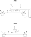
- FIG. 7 is a side view showing another embodiment of the substrate cleaning apparatus
- FIG. 8 is a view of two-fluid jet nozzle 2 and fan spray nozzle 3 shown in FIG. 7 as viewed from axial direction of arm 17.
- FIG. 9 is a top view of the substrate cleaning apparatus shown in FIG. 7 .
- the nozzle moving device 15 is configured to translate the two-fluid jet nozzle 2 and the fan spray nozzle 3 together. Both the two-fluid jet nozzle 2 and the fan spray nozzle 3 are held by the arm 17.
- the fan spray nozzle 3 is attached to a bracket 35 fixed to the arm 17. In one embodiment, the fan spray nozzle 3 may be fixed directly to the arm 17. Since the fan spray nozzle 3 is coupled to the arm 17 in this way, the two-fluid jet nozzle 2 and the fan spray nozzle 3 move together with the pivoting motion of the arm 17.
- the fan spray nozzle 3 is located between the two-fluid jet nozzle 2 and the support shaft 18. Therefore, the fan spray nozzle 3 moves in a path different from that of the two-fluid jet nozzle 2.
- the two-fluid jet nozzle 2 and the fan spray nozzle 3 deliver the two-fluid jet and the fan-shaped jet to the surface (upper surface) of the wafer W.
- the fan spray nozzle 3 is oriented in a direction perpendicular to the extending direction of the arm 17 as viewed from above. Therefore, the fan spray nozzle 3 emits the fan-shaped jet in the moving direction of the fan spray nozzle 3 as viewed from above.
- the fan spray nozzle 3 is arranged away from the two-fluid jet nozzle 2 at a distance such that the fan-shaped jet does not collide with the two-fluid jet.
- the fan spray nozzle 3 emits the fan-shaped jet in a direction away from the two-fluid jet nozzle 2 and the two-fluid jet, so that the fan-shaped jet does not collide with the two-fluid jet.
- the inclination angle of the fan spray nozzle 3 is the same as the angle described with reference to FIG. 5 .
- the fan spray nozzle 3 can deliver the fan-shaped jet of the second liquid to the surface (upper surface) of the wafer W while the fan spray nozzle 3 is moving. Therefore, the flow of the second liquid can be formed over a wide area on the surface (upper surface) of the wafer W. The flow of the second liquid can wash out the particles lifted by the two-fluid jet and can prevent the semidry of the wafer W.
- step 1 the periphery of the wafer W is held by the holding rollers 6. As shown in FIG. 4B , the periphery of the wafer W is held by each substrate holding surface 6a of each holding roller 6.
- step 2 the roller motors 8 shown in FIG. 1 are set in motion to rotate the holding rollers 6 about the respective central axes CP.
- the wafer W is rotated about the central axis of the wafer W by the rotating holding rollers 6.
- step 3 the arm 17 pivots around the support shaft 18 to move the two-fluid jet nozzle 2 and the fan spray nozzle 3 together, while the fluid jet nozzle 2 delivers the two-fluid jet composed of a mixture of the first liquid and the gas to the surface (upper surface) of the wafer W, and the fan spray nozzle 3 delivers the fan-shaped jet of the second liquid to the surface (upper surface) of the wafer W.
- the moving direction of the two-fluid jet nozzle 2 is the radial direction of the wafer W.
- the emission of the fan-shaped jet begins at the same time as or after the emission of the two-fluid jet begins.
- the two-fluid jet nozzle 2 reciprocates between the center of the rotating wafer W and the periphery of the wafer W by a predetermined number of times.
- step 4 the emission of the two-fluid jet is stopped, and at the same time or thereafter, the emission of the fan-shaped jet is stopped.
- step 5 the rinsing liquid is supplied from the rinsing nozzle 30 to the surface (upper surface) of the wafer W while the rotation of the wafer W is maintained, whereby the surface of the wafer W is rinsed with the rinsing liquid.
- step 6 the roller motors 8 are stopped, whereby the rotation of the wafer W is stopped.
- the present invention is applicable to a substrate cleaning method and a substrate cleaning apparatus for cleaning a substrate, such as a wafer.
Landscapes
- Cleaning Or Drying Semiconductors (AREA)
Claims (12)
- Procédé de nettoyage d'un substrat comprenant :la rotation du substrat (W) autour de son axe central ;la fourniture d'un jet à deux fluides depuis une buse à jet à deux fluides (2) vers une surface du substrat (W) tout en déplaçant la buse à jet à deux fluides (2) dans une direction radiale du substrat (W), le jet à deux fluides étant composé d'un mélange d'un premier liquide et d'un gaz ; etlorsque le jet à deux fluides est en cours de fourniture à la surface du substrat (W), la fourniture d'un jet en forme d'éventail d'un deuxième liquide depuis une buse de pulvérisation en forme d'éventail (3) vers la surface du substrat pour former un écoulement du deuxième liquide sur la surface du substrat (W), le jet en forme d'éventail étant situé à l'écart du jet à deux fluides,caractérisé en ce quela buse de pulvérisation en forme d'éventail (3) est orientée dans la direction de sorte qu'à la fois le jet en forme d'éventail émis par la buse de pulvérisation en forme d'éventail (3) et un écoulement du deuxième liquide formé sur la surface de la tranche (W) ne rencontrent pas le jet à deux fluides émis par la buse à jet à deux fluides (2).
- Procédé de nettoyage de substrat selon la revendication 1, dans lequel un angle de la buse de pulvérisation (3) par rapport à la surface du substrat (W) est dans une plage allant de 15° à 45°.
- Procédé de nettoyage de substrat selon la revendication 1 ou 2, dans lequel une largeur du jet en forme d'éventail est au moins égale aux trois quarts d'un rayon du substrat (W).
- Procédé de nettoyage de substrat selon l'une quelconque des revendications 1 à 3, dans lequel une direction du jet en forme d'éventail est orientée vers l'extérieur du substrat (W) .
- Procédé de nettoyage de substrat selon l'une quelconque des revendications 1 à 4, dans lequel la buse de pulvérisation (3) est située au-dessus du substrat.
- Procédé de nettoyage de substrat selon l'une quelconque des revendications 1 à 5, dans lequel la délivrance du jet en forme d'éventail comprend la fourniture du jet en forme d'éventail depuis la buse de pulvérisation (3) vers la surface du substrat (W) pour former l'écoulement du deuxième liquide sur la surface du substrat (W) tout en déplaçant la buse de pulvérisation (3) .
- Procédé de nettoyage de substrat selon la revendication 6, dans lequel la buse à jet à deux fluides (2) et la buse de pulvérisation (3) sont fixées sur un bras commun.
- Appareil de nettoyage de substrat comprenant :un porte-substrat (1) configuré pour maintenir un substrat (W) et faire tourner le substrat (W) autour d'un axe central du substrat (W) ;une buse à jet à deux fluides (2) configurée pour former un jet à deux fluides composé d'un mélange d'un premier liquide et d'un gaz ;une buse de pulvérisation en éventail (3) configurée pour former un jet en forme d'éventail d'un deuxième liquide ; etun dispositif de déplacement de buse (15) configuré pour déplacer la buse à jet à deux fluides (2), la buse à jet à deux fluides (2) et la buse de pulvérisation en éventail (3) étant orientées vers une surface du substrat (W),caractérisé en ce que la buse de pulvérisation en forme d'éventail (3) est orientée dans une direction dans laquelle à la fois le jet en forme d'éventail et un écoulement du deuxième liquide formé sur la surface de la tranche (W) ne rencontrent pas le jet à deux fluides.
- Appareil de nettoyage de substrat selon la revendication 9, dans lequel un angle de la buse de pulvérisation (3) par rapport à la surface du substrat (W) est dans une plage allant de 15° à 45°.
- Appareil de nettoyage de substrat selon la revendication 9 ou 10, dans lequel la buse de pulvérisation en forme d'éventail (3) est configurée pour former le jet en forme d'éventail d'une largeur au moins égale aux trois quarts du rayon du substrat (W).
- Appareil de nettoyage de substrat selon l'une quelconque des revendications 8 à 10, dans lequel le dispositif de déplacement de buse (15) comporte un bras (17) maintenant la buse à jet à deux fluides (2) et la buse de pulvérisation en éventail (3) .
- Appareil de nettoyage de substrat selon l'une quelconque des revendications 8 à 11, dans lequel le porte-substrat (1) comporte des rouleaux de maintien (6) configurés pour maintenir une périphérie du substrat (W), et chacun des rouleaux de maintien (6) comporte une surface cylindrique de maintien de substrat (6a) et une partie effilée (6b) inclinée vers le bas le long d'une direction radiale vers l'extérieur.
Applications Claiming Priority (2)
| Application Number | Priority Date | Filing Date | Title |
|---|---|---|---|
| JP2019150159A JP7285166B2 (ja) | 2019-08-20 | 2019-08-20 | 基板洗浄方法および基板洗浄装置 |
| PCT/JP2020/027253 WO2021033460A1 (fr) | 2019-08-20 | 2020-07-13 | Procédé de nettoyage de substrat et dispositif de nettoyage de substrat |
Publications (3)
| Publication Number | Publication Date |
|---|---|
| EP4020528A1 EP4020528A1 (fr) | 2022-06-29 |
| EP4020528A4 EP4020528A4 (fr) | 2023-08-09 |
| EP4020528B1 true EP4020528B1 (fr) | 2024-09-04 |
Family
ID=74661027
Family Applications (1)
| Application Number | Title | Priority Date | Filing Date |
|---|---|---|---|
| EP20854337.1A Active EP4020528B1 (fr) | 2019-08-20 | 2020-07-13 | Procédé de nettoyage de substrat et appareil de nettoyage de substrat |
Country Status (6)
| Country | Link |
|---|---|
| US (1) | US12030092B2 (fr) |
| EP (1) | EP4020528B1 (fr) |
| JP (1) | JP7285166B2 (fr) |
| KR (1) | KR102780279B1 (fr) |
| TW (1) | TWI884968B (fr) |
| WO (1) | WO2021033460A1 (fr) |
Families Citing this family (2)
| Publication number | Priority date | Publication date | Assignee | Title |
|---|---|---|---|---|
| KR102648888B1 (ko) | 2022-10-06 | 2024-03-18 | 세메스 주식회사 | 기판 처리 장치 |
| CN115582333B (zh) * | 2022-10-24 | 2023-09-01 | 苏州智程半导体科技股份有限公司 | 半导体晶圆翻转式清洗装置 |
Family Cites Families (7)
| Publication number | Priority date | Publication date | Assignee | Title |
|---|---|---|---|---|
| JP2006093497A (ja) * | 2004-09-27 | 2006-04-06 | Dainippon Screen Mfg Co Ltd | 基板洗浄装置 |
| JP5852898B2 (ja) * | 2011-03-28 | 2016-02-03 | 株式会社Screenホールディングス | 基板処理装置および基板処理方法 |
| JP6600470B2 (ja) * | 2014-04-01 | 2019-10-30 | 株式会社荏原製作所 | 洗浄装置及び洗浄方法 |
| JP2017147334A (ja) | 2016-02-17 | 2017-08-24 | 株式会社荏原製作所 | 基板の裏面を洗浄する装置および方法 |
| KR102338647B1 (ko) | 2016-05-09 | 2021-12-13 | 가부시키가이샤 에바라 세이사꾸쇼 | 기판 세정 장치 |
| JP6966917B2 (ja) * | 2017-10-12 | 2021-11-17 | 株式会社Screenホールディングス | 基板処理方法および基板処理装置 |
| CN208800297U (zh) * | 2018-07-30 | 2019-04-30 | 无锡市伟丰印刷机械厂 | 一种旋转喷头 |
-
2019
- 2019-08-20 JP JP2019150159A patent/JP7285166B2/ja active Active
-
2020
- 2020-07-13 KR KR1020227008329A patent/KR102780279B1/ko active Active
- 2020-07-13 US US17/636,299 patent/US12030092B2/en active Active
- 2020-07-13 EP EP20854337.1A patent/EP4020528B1/fr active Active
- 2020-07-13 WO PCT/JP2020/027253 patent/WO2021033460A1/fr not_active Ceased
- 2020-07-21 TW TW109124535A patent/TWI884968B/zh active
Also Published As
| Publication number | Publication date |
|---|---|
| JP2021034434A (ja) | 2021-03-01 |
| TWI884968B (zh) | 2025-06-01 |
| US12030092B2 (en) | 2024-07-09 |
| KR20220047335A (ko) | 2022-04-15 |
| TW202128291A (zh) | 2021-08-01 |
| WO2021033460A1 (fr) | 2021-02-25 |
| EP4020528A4 (fr) | 2023-08-09 |
| JP7285166B2 (ja) | 2023-06-01 |
| KR102780279B1 (ko) | 2025-03-14 |
| CN114270475A (zh) | 2022-04-01 |
| US20220288650A1 (en) | 2022-09-15 |
| EP4020528A1 (fr) | 2022-06-29 |
Similar Documents
| Publication | Publication Date | Title |
|---|---|---|
| JP6521242B2 (ja) | 基板処理方法および基板処理装置 | |
| KR101990161B1 (ko) | 액 처리 장치 | |
| KR101760306B1 (ko) | 액처리 방법 및 액처리 장치 | |
| US6942737B2 (en) | Substrate cleaning apparatus and method | |
| KR100877276B1 (ko) | 기판처리장치, 액막동결방법 및 기판처리방법 | |
| JP4976949B2 (ja) | 基板処理装置 | |
| US20130020284A1 (en) | Substrate processing apparatus and substrate processing method using processing solution | |
| CN103165496B (zh) | 基板处理装置和基板处理方法 | |
| TWI698922B (zh) | 基板處理方法及基板處理裝置 | |
| JP5973901B2 (ja) | 基板液処理装置及び基板液処理方法 | |
| KR101962542B1 (ko) | 기판 처리 장치 | |
| JP6775638B2 (ja) | 基板洗浄装置 | |
| CN108335995A (zh) | 基板处理装置、基板处理方法及计算机可读取的记录介质 | |
| EP4020528B1 (fr) | Procédé de nettoyage de substrat et appareil de nettoyage de substrat | |
| US10546763B2 (en) | Substrate treatment method and substrate treatment device | |
| JP2004235216A (ja) | 基板処理装置及び方法 | |
| CN114270475B (en) | Substrate cleaning method and substrate cleaning device | |
| CN112885739B (zh) | 基片处理装置和基片处理方法 | |
| TWI747060B (zh) | 處理杯單元及基板處理裝置 | |
| JP5970102B2 (ja) | 液処理装置 | |
| JP2023170626A (ja) | 基板処理装置 |
Legal Events
| Date | Code | Title | Description |
|---|---|---|---|
| STAA | Information on the status of an ep patent application or granted ep patent |
Free format text: STATUS: THE INTERNATIONAL PUBLICATION HAS BEEN MADE |
|
| PUAI | Public reference made under article 153(3) epc to a published international application that has entered the european phase |
Free format text: ORIGINAL CODE: 0009012 |
|
| STAA | Information on the status of an ep patent application or granted ep patent |
Free format text: STATUS: REQUEST FOR EXAMINATION WAS MADE |
|
| 17P | Request for examination filed |
Effective date: 20220216 |
|
| AK | Designated contracting states |
Kind code of ref document: A1 Designated state(s): AL AT BE BG CH CY CZ DE DK EE ES FI FR GB GR HR HU IE IS IT LI LT LU LV MC MK MT NL NO PL PT RO RS SE SI SK SM TR |
|
| DAV | Request for validation of the european patent (deleted) | ||
| DAX | Request for extension of the european patent (deleted) | ||
| REG | Reference to a national code |
Ref country code: DE Free format text: PREVIOUS MAIN CLASS: H01L0021304000 Ref country code: DE Ref legal event code: R079 Ref document number: 602020037288 Country of ref document: DE Free format text: PREVIOUS MAIN CLASS: H01L0021304000 Ipc: H01L0021670000 |
|
| A4 | Supplementary search report drawn up and despatched |
Effective date: 20230710 |
|
| RAP3 | Party data changed (applicant data changed or rights of an application transferred) |
Owner name: EBARA CORPORATION |
|
| RIC1 | Information provided on ipc code assigned before grant |
Ipc: H01L 21/687 20060101ALI20230704BHEP Ipc: H01L 21/67 20060101AFI20230704BHEP |
|
| GRAP | Despatch of communication of intention to grant a patent |
Free format text: ORIGINAL CODE: EPIDOSNIGR1 |
|
| STAA | Information on the status of an ep patent application or granted ep patent |
Free format text: STATUS: GRANT OF PATENT IS INTENDED |
|
| INTG | Intention to grant announced |
Effective date: 20240404 |
|
| GRAS | Grant fee paid |
Free format text: ORIGINAL CODE: EPIDOSNIGR3 |
|
| GRAA | (expected) grant |
Free format text: ORIGINAL CODE: 0009210 |
|
| STAA | Information on the status of an ep patent application or granted ep patent |
Free format text: STATUS: THE PATENT HAS BEEN GRANTED |
|
| P01 | Opt-out of the competence of the unified patent court (upc) registered |
Free format text: CASE NUMBER: APP_40765/2024 Effective date: 20240710 |
|
| AK | Designated contracting states |
Kind code of ref document: B1 Designated state(s): AL AT BE BG CH CY CZ DE DK EE ES FI FR GB GR HR HU IE IS IT LI LT LU LV MC MK MT NL NO PL PT RO RS SE SI SK SM TR |
|
| REG | Reference to a national code |
Ref country code: GB Ref legal event code: FG4D |
|
| REG | Reference to a national code |
Ref country code: CH Ref legal event code: EP |
|
| REG | Reference to a national code |
Ref country code: IE Ref legal event code: FG4D |
|
| REG | Reference to a national code |
Ref country code: DE Ref legal event code: R096 Ref document number: 602020037288 Country of ref document: DE |
|
| REG | Reference to a national code |
Ref country code: LT Ref legal event code: MG9D |
|
| REG | Reference to a national code |
Ref country code: NL Ref legal event code: MP Effective date: 20240904 |
|
| PG25 | Lapsed in a contracting state [announced via postgrant information from national office to epo] |
Ref country code: NO Free format text: LAPSE BECAUSE OF FAILURE TO SUBMIT A TRANSLATION OF THE DESCRIPTION OR TO PAY THE FEE WITHIN THE PRESCRIBED TIME-LIMIT Effective date: 20241204 |
|
| PG25 | Lapsed in a contracting state [announced via postgrant information from national office to epo] |
Ref country code: GR Free format text: LAPSE BECAUSE OF FAILURE TO SUBMIT A TRANSLATION OF THE DESCRIPTION OR TO PAY THE FEE WITHIN THE PRESCRIBED TIME-LIMIT Effective date: 20241205 Ref country code: PL Free format text: LAPSE BECAUSE OF FAILURE TO SUBMIT A TRANSLATION OF THE DESCRIPTION OR TO PAY THE FEE WITHIN THE PRESCRIBED TIME-LIMIT Effective date: 20240904 Ref country code: FI Free format text: LAPSE BECAUSE OF FAILURE TO SUBMIT A TRANSLATION OF THE DESCRIPTION OR TO PAY THE FEE WITHIN THE PRESCRIBED TIME-LIMIT Effective date: 20240904 |
|
| PG25 | Lapsed in a contracting state [announced via postgrant information from national office to epo] |
Ref country code: BG Free format text: LAPSE BECAUSE OF FAILURE TO SUBMIT A TRANSLATION OF THE DESCRIPTION OR TO PAY THE FEE WITHIN THE PRESCRIBED TIME-LIMIT Effective date: 20240904 |
|
| PG25 | Lapsed in a contracting state [announced via postgrant information from national office to epo] |
Ref country code: LV Free format text: LAPSE BECAUSE OF FAILURE TO SUBMIT A TRANSLATION OF THE DESCRIPTION OR TO PAY THE FEE WITHIN THE PRESCRIBED TIME-LIMIT Effective date: 20240904 |
|
| PG25 | Lapsed in a contracting state [announced via postgrant information from national office to epo] |
Ref country code: HR Free format text: LAPSE BECAUSE OF FAILURE TO SUBMIT A TRANSLATION OF THE DESCRIPTION OR TO PAY THE FEE WITHIN THE PRESCRIBED TIME-LIMIT Effective date: 20240904 |
|
| PG25 | Lapsed in a contracting state [announced via postgrant information from national office to epo] |
Ref country code: ES Free format text: LAPSE BECAUSE OF FAILURE TO SUBMIT A TRANSLATION OF THE DESCRIPTION OR TO PAY THE FEE WITHIN THE PRESCRIBED TIME-LIMIT Effective date: 20240904 Ref country code: RS Free format text: LAPSE BECAUSE OF FAILURE TO SUBMIT A TRANSLATION OF THE DESCRIPTION OR TO PAY THE FEE WITHIN THE PRESCRIBED TIME-LIMIT Effective date: 20241204 |
|
| PG25 | Lapsed in a contracting state [announced via postgrant information from national office to epo] |
Ref country code: RS Free format text: LAPSE BECAUSE OF FAILURE TO SUBMIT A TRANSLATION OF THE DESCRIPTION OR TO PAY THE FEE WITHIN THE PRESCRIBED TIME-LIMIT Effective date: 20241204 Ref country code: PL Free format text: LAPSE BECAUSE OF FAILURE TO SUBMIT A TRANSLATION OF THE DESCRIPTION OR TO PAY THE FEE WITHIN THE PRESCRIBED TIME-LIMIT Effective date: 20240904 Ref country code: NO Free format text: LAPSE BECAUSE OF FAILURE TO SUBMIT A TRANSLATION OF THE DESCRIPTION OR TO PAY THE FEE WITHIN THE PRESCRIBED TIME-LIMIT Effective date: 20241204 Ref country code: LV Free format text: LAPSE BECAUSE OF FAILURE TO SUBMIT A TRANSLATION OF THE DESCRIPTION OR TO PAY THE FEE WITHIN THE PRESCRIBED TIME-LIMIT Effective date: 20240904 Ref country code: HR Free format text: LAPSE BECAUSE OF FAILURE TO SUBMIT A TRANSLATION OF THE DESCRIPTION OR TO PAY THE FEE WITHIN THE PRESCRIBED TIME-LIMIT Effective date: 20240904 Ref country code: GR Free format text: LAPSE BECAUSE OF FAILURE TO SUBMIT A TRANSLATION OF THE DESCRIPTION OR TO PAY THE FEE WITHIN THE PRESCRIBED TIME-LIMIT Effective date: 20241205 Ref country code: FI Free format text: LAPSE BECAUSE OF FAILURE TO SUBMIT A TRANSLATION OF THE DESCRIPTION OR TO PAY THE FEE WITHIN THE PRESCRIBED TIME-LIMIT Effective date: 20240904 Ref country code: ES Free format text: LAPSE BECAUSE OF FAILURE TO SUBMIT A TRANSLATION OF THE DESCRIPTION OR TO PAY THE FEE WITHIN THE PRESCRIBED TIME-LIMIT Effective date: 20240904 Ref country code: BG Free format text: LAPSE BECAUSE OF FAILURE TO SUBMIT A TRANSLATION OF THE DESCRIPTION OR TO PAY THE FEE WITHIN THE PRESCRIBED TIME-LIMIT Effective date: 20240904 |
|
| REG | Reference to a national code |
Ref country code: AT Ref legal event code: MK05 Ref document number: 1721340 Country of ref document: AT Kind code of ref document: T Effective date: 20240904 |
|
| PG25 | Lapsed in a contracting state [announced via postgrant information from national office to epo] |
Ref country code: NL Free format text: LAPSE BECAUSE OF FAILURE TO SUBMIT A TRANSLATION OF THE DESCRIPTION OR TO PAY THE FEE WITHIN THE PRESCRIBED TIME-LIMIT Effective date: 20240904 |
|
| PG25 | Lapsed in a contracting state [announced via postgrant information from national office to epo] |
Ref country code: PT Free format text: LAPSE BECAUSE OF FAILURE TO SUBMIT A TRANSLATION OF THE DESCRIPTION OR TO PAY THE FEE WITHIN THE PRESCRIBED TIME-LIMIT Effective date: 20250106 Ref country code: IS Free format text: LAPSE BECAUSE OF FAILURE TO SUBMIT A TRANSLATION OF THE DESCRIPTION OR TO PAY THE FEE WITHIN THE PRESCRIBED TIME-LIMIT Effective date: 20250104 |
|
| PG25 | Lapsed in a contracting state [announced via postgrant information from national office to epo] |
Ref country code: RO Free format text: LAPSE BECAUSE OF FAILURE TO SUBMIT A TRANSLATION OF THE DESCRIPTION OR TO PAY THE FEE WITHIN THE PRESCRIBED TIME-LIMIT Effective date: 20240904 Ref country code: SM Free format text: LAPSE BECAUSE OF FAILURE TO SUBMIT A TRANSLATION OF THE DESCRIPTION OR TO PAY THE FEE WITHIN THE PRESCRIBED TIME-LIMIT Effective date: 20240904 |
|
| PG25 | Lapsed in a contracting state [announced via postgrant information from national office to epo] |
Ref country code: AT Free format text: LAPSE BECAUSE OF FAILURE TO SUBMIT A TRANSLATION OF THE DESCRIPTION OR TO PAY THE FEE WITHIN THE PRESCRIBED TIME-LIMIT Effective date: 20240904 Ref country code: EE Free format text: LAPSE BECAUSE OF FAILURE TO SUBMIT A TRANSLATION OF THE DESCRIPTION OR TO PAY THE FEE WITHIN THE PRESCRIBED TIME-LIMIT Effective date: 20240904 |
|
| PG25 | Lapsed in a contracting state [announced via postgrant information from national office to epo] |
Ref country code: CZ Free format text: LAPSE BECAUSE OF FAILURE TO SUBMIT A TRANSLATION OF THE DESCRIPTION OR TO PAY THE FEE WITHIN THE PRESCRIBED TIME-LIMIT Effective date: 20240904 |
|
| PG25 | Lapsed in a contracting state [announced via postgrant information from national office to epo] |
Ref country code: IT Free format text: LAPSE BECAUSE OF FAILURE TO SUBMIT A TRANSLATION OF THE DESCRIPTION OR TO PAY THE FEE WITHIN THE PRESCRIBED TIME-LIMIT Effective date: 20240904 Ref country code: SK Free format text: LAPSE BECAUSE OF FAILURE TO SUBMIT A TRANSLATION OF THE DESCRIPTION OR TO PAY THE FEE WITHIN THE PRESCRIBED TIME-LIMIT Effective date: 20240904 |
|
| REG | Reference to a national code |
Ref country code: DE Ref legal event code: R097 Ref document number: 602020037288 Country of ref document: DE |
|
| PG25 | Lapsed in a contracting state [announced via postgrant information from national office to epo] |
Ref country code: DK Free format text: LAPSE BECAUSE OF FAILURE TO SUBMIT A TRANSLATION OF THE DESCRIPTION OR TO PAY THE FEE WITHIN THE PRESCRIBED TIME-LIMIT Effective date: 20240904 |
|
| PLBE | No opposition filed within time limit |
Free format text: ORIGINAL CODE: 0009261 |
|
| STAA | Information on the status of an ep patent application or granted ep patent |
Free format text: STATUS: NO OPPOSITION FILED WITHIN TIME LIMIT |
|
| 26N | No opposition filed |
Effective date: 20250605 |
|
| PG25 | Lapsed in a contracting state [announced via postgrant information from national office to epo] |
Ref country code: SE Free format text: LAPSE BECAUSE OF FAILURE TO SUBMIT A TRANSLATION OF THE DESCRIPTION OR TO PAY THE FEE WITHIN THE PRESCRIBED TIME-LIMIT Effective date: 20240904 |
|
| PGFP | Annual fee paid to national office [announced via postgrant information from national office to epo] |
Ref country code: DE Payment date: 20250918 Year of fee payment: 6 |
|
| PGFP | Annual fee paid to national office [announced via postgrant information from national office to epo] |
Ref country code: FR Payment date: 20250716 Year of fee payment: 6 |
|
| REG | Reference to a national code |
Ref country code: DE Ref legal event code: R079 Ref document number: 602020037288 Country of ref document: DE Free format text: PREVIOUS MAIN CLASS: H01L0021670000 Ipc: H10P0072000000 |
|
| REG | Reference to a national code |
Ref country code: CH Ref legal event code: H13 Free format text: ST27 STATUS EVENT CODE: U-0-0-H10-H13 (AS PROVIDED BY THE NATIONAL OFFICE) Effective date: 20260224 |
|
| PG25 | Lapsed in a contracting state [announced via postgrant information from national office to epo] |
Ref country code: LU Free format text: LAPSE BECAUSE OF NON-PAYMENT OF DUE FEES Effective date: 20250713 |
|
| GBPC | Gb: european patent ceased through non-payment of renewal fee |
Effective date: 20250713 |
|
| REG | Reference to a national code |
Ref country code: BE Ref legal event code: MM Effective date: 20250731 |
|
| PG25 | Lapsed in a contracting state [announced via postgrant information from national office to epo] |
Ref country code: GB Free format text: LAPSE BECAUSE OF NON-PAYMENT OF DUE FEES Effective date: 20250713 |
|
| PG25 | Lapsed in a contracting state [announced via postgrant information from national office to epo] |
Ref country code: BE Free format text: LAPSE BECAUSE OF NON-PAYMENT OF DUE FEES Effective date: 20250731 |
|
| PG25 | Lapsed in a contracting state [announced via postgrant information from national office to epo] |
Ref country code: CH Free format text: LAPSE BECAUSE OF NON-PAYMENT OF DUE FEES Effective date: 20250731 |