EP4020672B1 - Battery pack and device including same - Google Patents
Battery pack and device including same Download PDFInfo
- Publication number
- EP4020672B1 EP4020672B1 EP21796245.5A EP21796245A EP4020672B1 EP 4020672 B1 EP4020672 B1 EP 4020672B1 EP 21796245 A EP21796245 A EP 21796245A EP 4020672 B1 EP4020672 B1 EP 4020672B1
- Authority
- EP
- European Patent Office
- Prior art keywords
- battery
- module
- pack
- lower cover
- refrigerant
- Prior art date
- Legal status (The legal status is an assumption and is not a legal conclusion. Google has not performed a legal analysis and makes no representation as to the accuracy of the status listed.)
- Active
Links
Images


Classifications
-
- H—ELECTRICITY
- H01—ELECTRIC ELEMENTS
- H01M—PROCESSES OR MEANS, e.g. BATTERIES, FOR THE DIRECT CONVERSION OF CHEMICAL ENERGY INTO ELECTRICAL ENERGY
- H01M10/00—Secondary cells; Manufacture thereof
- H01M10/60—Heating or cooling; Temperature control
- H01M10/61—Types of temperature control
- H01M10/613—Cooling or keeping cold
-
- H—ELECTRICITY
- H01—ELECTRIC ELEMENTS
- H01M—PROCESSES OR MEANS, e.g. BATTERIES, FOR THE DIRECT CONVERSION OF CHEMICAL ENERGY INTO ELECTRICAL ENERGY
- H01M10/00—Secondary cells; Manufacture thereof
- H01M10/60—Heating or cooling; Temperature control
- H01M10/65—Means for temperature control structurally associated with the cells
- H01M10/655—Solid structures for heat exchange or heat conduction
- H01M10/6556—Solid parts with flow channel passages or pipes for heat exchange
-
- H—ELECTRICITY
- H01—ELECTRIC ELEMENTS
- H01M—PROCESSES OR MEANS, e.g. BATTERIES, FOR THE DIRECT CONVERSION OF CHEMICAL ENERGY INTO ELECTRICAL ENERGY
- H01M50/00—Constructional details or processes of manufacture of the non-active parts of electrochemical cells other than fuel cells, e.g. hybrid cells
- H01M50/20—Mountings; Secondary casings or frames; Racks, modules or packs; Suspension devices; Shock absorbers; Transport or carrying devices; Holders
- H01M50/204—Racks, modules or packs for multiple batteries or multiple cells
- H01M50/207—Racks, modules or packs for multiple batteries or multiple cells characterised by their shape
- H01M50/211—Racks, modules or packs for multiple batteries or multiple cells characterised by their shape adapted for pouch cells
-
- H—ELECTRICITY
- H01—ELECTRIC ELEMENTS
- H01M—PROCESSES OR MEANS, e.g. BATTERIES, FOR THE DIRECT CONVERSION OF CHEMICAL ENERGY INTO ELECTRICAL ENERGY
- H01M10/00—Secondary cells; Manufacture thereof
- H01M10/60—Heating or cooling; Temperature control
- H01M10/65—Means for temperature control structurally associated with the cells
- H01M10/653—Means for temperature control structurally associated with the cells characterised by electrically insulating or thermally conductive materials
-
- H—ELECTRICITY
- H01—ELECTRIC ELEMENTS
- H01M—PROCESSES OR MEANS, e.g. BATTERIES, FOR THE DIRECT CONVERSION OF CHEMICAL ENERGY INTO ELECTRICAL ENERGY
- H01M10/00—Secondary cells; Manufacture thereof
- H01M10/60—Heating or cooling; Temperature control
- H01M10/65—Means for temperature control structurally associated with the cells
- H01M10/655—Solid structures for heat exchange or heat conduction
- H01M10/6551—Surfaces specially adapted for heat dissipation or radiation, e.g. fins or coatings
-
- H—ELECTRICITY
- H01—ELECTRIC ELEMENTS
- H01M—PROCESSES OR MEANS, e.g. BATTERIES, FOR THE DIRECT CONVERSION OF CHEMICAL ENERGY INTO ELECTRICAL ENERGY
- H01M10/00—Secondary cells; Manufacture thereof
- H01M10/60—Heating or cooling; Temperature control
- H01M10/65—Means for temperature control structurally associated with the cells
- H01M10/655—Solid structures for heat exchange or heat conduction
- H01M10/6554—Rods or plates
-
- H—ELECTRICITY
- H01—ELECTRIC ELEMENTS
- H01M—PROCESSES OR MEANS, e.g. BATTERIES, FOR THE DIRECT CONVERSION OF CHEMICAL ENERGY INTO ELECTRICAL ENERGY
- H01M10/00—Secondary cells; Manufacture thereof
- H01M10/60—Heating or cooling; Temperature control
- H01M10/65—Means for temperature control structurally associated with the cells
- H01M10/656—Means for temperature control structurally associated with the cells characterised by the type of heat-exchange fluid
- H01M10/6567—Liquids
- H01M10/6568—Liquids characterised by flow circuits, e.g. loops, located externally to the cells or cell casings
-
- H—ELECTRICITY
- H01—ELECTRIC ELEMENTS
- H01M—PROCESSES OR MEANS, e.g. BATTERIES, FOR THE DIRECT CONVERSION OF CHEMICAL ENERGY INTO ELECTRICAL ENERGY
- H01M50/00—Constructional details or processes of manufacture of the non-active parts of electrochemical cells other than fuel cells, e.g. hybrid cells
- H01M50/20—Mountings; Secondary casings or frames; Racks, modules or packs; Suspension devices; Shock absorbers; Transport or carrying devices; Holders
- H01M50/204—Racks, modules or packs for multiple batteries or multiple cells
- H01M50/207—Racks, modules or packs for multiple batteries or multiple cells characterised by their shape
- H01M50/209—Racks, modules or packs for multiple batteries or multiple cells characterised by their shape adapted for prismatic or rectangular cells
-
- H—ELECTRICITY
- H01—ELECTRIC ELEMENTS
- H01M—PROCESSES OR MEANS, e.g. BATTERIES, FOR THE DIRECT CONVERSION OF CHEMICAL ENERGY INTO ELECTRICAL ENERGY
- H01M50/00—Constructional details or processes of manufacture of the non-active parts of electrochemical cells other than fuel cells, e.g. hybrid cells
- H01M50/20—Mountings; Secondary casings or frames; Racks, modules or packs; Suspension devices; Shock absorbers; Transport or carrying devices; Holders
- H01M50/233—Mountings; Secondary casings or frames; Racks, modules or packs; Suspension devices; Shock absorbers; Transport or carrying devices; Holders characterised by physical properties of casings or racks, e.g. dimensions
- H01M50/24—Mountings; Secondary casings or frames; Racks, modules or packs; Suspension devices; Shock absorbers; Transport or carrying devices; Holders characterised by physical properties of casings or racks, e.g. dimensions adapted for protecting batteries from their environment, e.g. from corrosion
-
- H—ELECTRICITY
- H01—ELECTRIC ELEMENTS
- H01M—PROCESSES OR MEANS, e.g. BATTERIES, FOR THE DIRECT CONVERSION OF CHEMICAL ENERGY INTO ELECTRICAL ENERGY
- H01M50/00—Constructional details or processes of manufacture of the non-active parts of electrochemical cells other than fuel cells, e.g. hybrid cells
- H01M50/20—Mountings; Secondary casings or frames; Racks, modules or packs; Suspension devices; Shock absorbers; Transport or carrying devices; Holders
- H01M50/271—Lids or covers for the racks or secondary casings
-
- H—ELECTRICITY
- H01—ELECTRIC ELEMENTS
- H01M—PROCESSES OR MEANS, e.g. BATTERIES, FOR THE DIRECT CONVERSION OF CHEMICAL ENERGY INTO ELECTRICAL ENERGY
- H01M2220/00—Batteries for particular applications
- H01M2220/20—Batteries in motive systems, e.g. vehicle, ship, plane
-
- H—ELECTRICITY
- H01—ELECTRIC ELEMENTS
- H01M—PROCESSES OR MEANS, e.g. BATTERIES, FOR THE DIRECT CONVERSION OF CHEMICAL ENERGY INTO ELECTRICAL ENERGY
- H01M2220/00—Batteries for particular applications
- H01M2220/30—Batteries in portable systems, e.g. mobile phone, laptop
-
- Y—GENERAL TAGGING OF NEW TECHNOLOGICAL DEVELOPMENTS; GENERAL TAGGING OF CROSS-SECTIONAL TECHNOLOGIES SPANNING OVER SEVERAL SECTIONS OF THE IPC; TECHNICAL SUBJECTS COVERED BY FORMER USPC CROSS-REFERENCE ART COLLECTIONS [XRACs] AND DIGESTS
- Y02—TECHNOLOGIES OR APPLICATIONS FOR MITIGATION OR ADAPTATION AGAINST CLIMATE CHANGE
- Y02E—REDUCTION OF GREENHOUSE GAS [GHG] EMISSIONS, RELATED TO ENERGY GENERATION, TRANSMISSION OR DISTRIBUTION
- Y02E60/00—Enabling technologies; Technologies with a potential or indirect contribution to GHG emissions mitigation
- Y02E60/10—Energy storage using batteries
-
- Y—GENERAL TAGGING OF NEW TECHNOLOGICAL DEVELOPMENTS; GENERAL TAGGING OF CROSS-SECTIONAL TECHNOLOGIES SPANNING OVER SEVERAL SECTIONS OF THE IPC; TECHNICAL SUBJECTS COVERED BY FORMER USPC CROSS-REFERENCE ART COLLECTIONS [XRACs] AND DIGESTS
- Y02—TECHNOLOGIES OR APPLICATIONS FOR MITIGATION OR ADAPTATION AGAINST CLIMATE CHANGE
- Y02T—CLIMATE CHANGE MITIGATION TECHNOLOGIES RELATED TO TRANSPORTATION
- Y02T10/00—Road transport of goods or passengers
- Y02T10/60—Other road transportation technologies with climate change mitigation effect
- Y02T10/70—Energy storage systems for electromobility, e.g. batteries
Definitions
- the present disclosure relates to a battery pack and a device including the same, and more particularly, to a battery pack preventing leakage of a refrigerant and a device including the same.
- chargeable/dischargeable secondary batteries are used as a power source for an electric vehicle (EV), a hybrid electric vehicle (HEV), a plug-in hybrid electric vehicle (P-HEV) and the like, in an attempt to solve air pollution and the like caused by existing gasoline vehicles using fossil fuel. Therefore, the need for development of the secondary battery is growing.
- EV electric vehicle
- HEV hybrid electric vehicle
- P-HEV plug-in hybrid electric vehicle
- the lithium secondary battery has come into the spotlight because they have advantages, for example, hardly exhibiting memory effects compared to nickel-based secondary batteries and thus being freely charged and discharged, and having very low self-discharge rate and high energy density.
- Such lithium secondary battery mainly uses a lithium-based oxide and a carbonaceous material as a positive electrode active material and a negative electrode active material, respectively.
- the lithium secondary battery includes an electrode assembly in which a positive electrode plate and a negative electrode plate respectively coated with the positive electrode active material and the negative electrode active material are disposed with a separator being interposed between them, and a battery case which seals and houses the electrode assembly together with an electrolyte solution.
- the lithium secondary battery may be classified based on the shape of the exterior material into a can type secondary battery in which the electrode assembly is built in a metal can, and a pouch-type secondary battery in which the electrode assembly is built in in a pouch of an aluminum laminate sheet.
- a battery module in which a large number of battery cells are electrically connected is used.
- a large number of battery cells are connected to each other in series or in parallel to form a cell stack, thereby improving capacity and output.
- one or more battery modules can be mounted together with various control and protection systems such as a battery management system (BMS) and a cooling system to form a battery pack.
- BMS battery management system
- a large number of secondary batteries that is, a battery module or a battery pack having battery cells, can add up the heat generated from the large number of battery cells in a narrow space, so that the temperature can rise more quickly and severely.
- a battery module in which a large number of battery cells are stacked, and a battery pack equipped with such a battery module can obtain high output, but it is not easy to remove heat generated from the battery cells during charging and discharging.
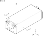
- Fig. 1 is a perspective view of a conventional battery module.
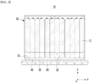
- Fig. 2 is a cross-sectional view taken along the cutting line A-A' of Fig. 1 .
- Fig. 2 additionally shows a heat transfer member and a heat sink located under the battery module.
- the conventional battery module 10 is configured such that a plurality of battery cells 11 are stacked to form a battery cell stack 20, and the battery cell stack 20 is housed in the module frame 30.
- the battery module 10 since the battery module 10 includes a plurality of battery cells 11, it generates a large amount of heat in a charge and discharge process.
- the battery module 10 may include a thermal conductive resin layer 40 that is located between the battery cell stack 20 and the bottom portion 31 of the module frame 30.
- a heat transfer member 50 and a heat sink 60 may be sequentially located under the battery module 10.
- the heat transfer member 50 may be a heat dissipation pad, and the heat sink 60 may have a refrigerant flow path formed therein.
- the heat generated from the battery cell 11 passes through the thermal conductive resin layer 40, the bottom portion 31 of the module frame 30, the heat transfer member 50, and the heat sink 60 in this order, and then is transferred to the outside of the battery module 10.
- the heat transfer path is complicated as described above, which makes it difficult to effectively transfer the heat generated from the battery cell 11.
- the module frame 30 itself may deteriorate heat transfer properties, and a fine air layer such as an air gap, which can be formed in the space between the module frame 30, the heat transfer member 50, and the heat sink 60, respectively, may also be a factor that deteriorates the heat transfer properties.
- the battery module since other demands such as downsizing of module and an increase in capacity are also continuing, it can be said that it is practically necessary to develop a battery module capable of satisfying these various requirements while improving the cooling performance.
- a battery pack comprising: a plurality of battery modules; a pack refrigerant tube assembly disposed between the battery modules facing each other among the plurality of battery modules; a pack refrigerant tube lower cover for covering the lower part of the pack refrigerant tube assembly; a module tray located at the lower side of the pack refrigerant tube lower cover; and a lower housing located at the lower side of the module tray, wherein a lower cover opening is formed in the pack refrigerant tube lower cover, and the lower cover opening is connected to a space formed between the module tray and the lower housing.
- the plurality of battery modules comprises a battery cell stack in which a plurality of battery cells are stacked; a module frame that houses the battery cell stack; a heat sink formed on the bottom portion of the module frame; and a cooling port that supplies a refrigerant to the heat sink and discharges the refrigerant from the heat sink, respectively, wherein the cooling port is located on the lower cover opening.
- the module frame includes a module frame protrusion part in which a part of the bottom portion of the module frame is formed in a protruding manner, and the cooling port may be formed in a protruding manner on the module frame protrusion part so as to pass through the inside of the lower cover opening from the lower side to the upper side.
- the cooling port formed in one battery module and the cooling port formed in another battery module are disposed so as to face each other, the lower cover opening is formed in plural numbers, and the two cooling ports disposed so as to face each other may be located together on one lower cover opening among the plurality of the lower cover openings.
- the module tray includes a module tray opening, and the cooling port may be located on the module tray opening.
- the lower cover opening may be connected to a space formed between the module tray and the lower housing through the module tray opening.
- the battery pack further includes a module tray gasket formed between the module tray and the lower housing, wherein the module tray gasket seals between the module tray and the lower housing.
- the module tray is integrally formed along the outer edge portion of each of the plurality of battery modules, and the module tray gasket may be formed along the outer edge portion of the module tray.
- the battery pack further includes a lower cover gasket formed between the pack refrigerant tube lower cover and the module tray, wherein the lower cover gasket may seal between the pack refrigerant tube lower cover and the module tray.
- the lower cover gasket may be formed outside the lower cover opening and the module tray opening.
- the battery pack may further include a pack refrigerant tube upper cover for covering the upper part of the pack refrigerant tube assembly.
- a device comprising the above-mentioned battery pack.
- planar when referred to as “planar”, it means when a target portion is viewed from the upper side, and when referred to as “cross-sectional”, it means when a target portion is viewed from the side of a cross section cut vertically.
- Fig. 3 is a perspective view showing a battery module according to embodiments of the present disclosure.
- Fig. 4 is an exploded perspective view of the battery module of Fig. 3 .
- Fig. 5 is a perspective view of the battery module of Fig. 3 as viewed from bottom to top of the battery module along the z-axis direction.
- a battery module 100 includes a battery cell stack 120 in which a plurality of battery cells 110 are stacked, a module frame 200 for housing battery cell stack 120, and a heat sink 300 located below the bottom portion 210a of the module frame 200.
- the bottom portion 210a of the module frame 200 constitutes an upper plate of the heat sink 300, and the recessed portion 340 of the heat sink 300 and the bottom portion 210a of the module frame 200 form a refrigerant flow path.
- the battery cell 110 may be a pouch-type battery cell.
- the pouch-type battery cell may be formed by housing an electrode assembly in a pouch case of a laminate sheet including a resin layer and a metal layer, and then heat-sealing a sealing part of the pouch case. At this time, the battery cell 110 may be formed in a rectangular sheet-like structure.
- the battery cells 110 may be composed of a plurality of cells, and the plurality of battery cells 110 are stacked so as to be electrically connected to each other, thereby forming a battery cell stack 120.
- a plurality of battery cells 110 may be stacked along a direction parallel to the x-axis.
- the module frame 200 for housing the battery cell stack 120 may include an upper cover 220 and a U-shaped frame 210.
- the U-shaped frame 210 may include a bottom portion 210a and two side portions 210b extending upward from both ends of the bottom portion 210a.
- the bottom portion 210a may cover the lower surface of the battery cell stack 120, and the side portions 210b may cover both side surfaces of the battery cell stack 120.
- the upper cover 220 may be formed in a single plate-shaped structure that wraps the lower surface wrapped by the U-shaped frame 210 and the remaining upper surface (z-axis direction) excluding the both side surfaces.
- the upper cover 220 and the U-shaped frame 210 can be joined by welding or the like in a state in which the corresponding corner portions are in contact with each other, thereby forming a structure that covers the battery cell stack 120 vertically and horizontally.
- the battery cell stack 120 can be physically protected through the upper cover 220 and the U-shaped frame 210.
- the upper cover 220 and the U-shaped frame 210 may include a metal material having a predetermined strength.
- the module frame 200 may be a mono frame in the form of a metal plate in which the upper surface, the lower surface, and both side surfaces are integrated. That is, this is not a structure in which the U-shaped frame 210 and the upper cover 220 are joined with each other, but a structure in which the upper surface, the lower surface, and both side surfaces are integrated by being manufactured by extrusion molding.
- the end plate 400 may be located on both open sides (y-axis direction) corresponding to each other of the module frame 200, so that it can be formed so as to cover the battery cell stack 120.
- the end plate 400 can physically protect the battery cell stack 120 and other electronic instruments from external impact.
- a busbar frame on which a busbar is mounted and an insulating cover for electrical insulation may be located between the battery cell stack 120 and the end plate 400.
- the module frame 200 includes a module frame protrusion part 211 formed so that the bottom portion 210a of the module frame 200 is extended and passes through the end plate 400. At this time, the refrigerant inflowing and discharging by the cooling port 500 connected to the upper surface of the module frame protrusion part 211 can be supplied to the heat sink 300 via the module frame protrusion part 211 and discharged from the heat sink 300.
- the cooling port 500 includes a refrigerant injection port 500a and a refrigerant discharge port 500b, and the refrigerant injection port 500a and the refrigerant discharge port 500b can be respectively connected to a pack refrigerant supply tube and a pack refrigerant discharge tube which are described later.
- the module frame protrusion part 211 includes a first module frame protrusion part and a second module frame protrusion part from one side of the module frame 200, the refrigerant injection port 500a may be disposed on the first module frame protrusion part, and the refrigerant discharge port 500b may be disposed on the second module frame protrusion part.
- a protrusion pattern 340D may be formed on the lower plate 310 of the heat sink 300 according to the embodiments of the present disclosure.
- the number of stacked battery cells is increased significantly compared to a conventional case, the width of the refrigerant flow path be formed wider and thus, a temperature deviation can be more severe.
- the large-area battery module it may include a case in which approximately 32 to 48 battery cells are stacked in one battery module, compared to a conventional case in which approximately 12 to 24 battery cells are stacked in one battery module.
- the protrusion pattern 340D can generate the effect of substantially reducing the width of the refrigerant flow path, thereby minimizing the pressure drop and at the same time, reducing the temperature deviation between the refrigerant flow path widths. Therefore, a uniform cooling effect can be realized.
- the bottom portion 210a of the module frame 200 constitutes an upper plate of the heat sink 300, and a recessed portion 340 of the heat sink 300 and the bottom portion 210a of the module frame 200 form a flow path for refrigerant.
- a heat sink 300 may be formed at a lower part of the module frame 200, and the heat sink 300 may include a lower plate 310 that forms a skeleton of the heat sink 300 and is directly coupled to the bottom portion 210a of the module frame 200 by welding, etc., an inlet 320 that is formed on one side of the heat sink 300 to supply a refrigerant to the inside of the heat sink 300 from the outside, an outlet 330 that is formed on one side of the heat sink 300 and enables the refrigerant flowing inside the heat sink 300 to flow to the outside of the heat sink 300, and a recessed portion 340 that connects the inlet 320 and the outlet 330 and enables the refrigerant to flow.
- the inlet 320 and the outlet 330 may be formed at positions corresponding to the module frame protrusion part 211 so as to be connected to the lower surface of the module frame protrusion part 211.
- the inlet 320 and the outlet 330 may be formed on the heat sink protrusion part 300P that is protruded from one side of the heat sink 300 to the portion where the module frame protrusion 211 is located.
- the heat sink protrusion 300P and the module frame protrusion 211 may be directly coupled to each other by welding or the like.
- the recessed portion 340 of the heat sink 300 corresponds to a portion in which the lower plate 310 is formed to be recessed on the lower side.
- the recessed portion 340 may be a tube in which a cross section cut perpendicularly to the xy plane with reference to the direction in which the refrigerant flow path extends has U-shape, and the bottom portion 210a may be located on the opened upper side of the U-shaped tube. While the heat sink 300 comes into contact with the bottom portion 210a, the space between the recessed portion 340 and the bottom portion 210a forms a region through which the refrigerant flows, that is, a refrigerant flow path. Thereby, the bottom portion 210a of the module frame 200 can come into direct contact with the refrigerant.
- the method of manufacturing the recessed portion 340 of the heat sink 300 is not particularly limited, but by providing a structure formed so as to be recessed with respect to a plate-shaped heat sink 300, a U-shaped recessed portion 340 with an opened upper side can be formed.
- a thermal conductive resin layer containing a thermal conductive resin may be located between the bottom portion 210a of the module frame 200 of Fig. 4 and the battery cell stack 120.
- the thermal conductive resin layer may be formed by applying a thermal conductive resin to the bottom portion 210a, and curing the applied thermal conductive resin.
- the thermal conductive resin may include a thermal conductive adhesive material, and specifically, may include at least one of silicone material, urethan material, and acrylic material.
- the thermal conductive resin is a liquid during application but is cured after application, so that it can perform the role of fixing one or more battery cells 110 constituting the battery cell stack 120. Further, since the thermal conductive resin has excellent heat transfer properties, heat generated from the battery cell 110 can be quickly transferred to the lower side of the battery module.
- the conventional battery module 10 shown in Fig. 2 is configured such that the heat generated from battery cells 11 passes through a thermal conductive resin layer 40, a bottom portion 31 of the module frame 30, a heat transfer member 50, and a refrigerant of a heat sink 60 in this order, and then is transferred to the outside of the battery module 10.
- the flow path for a refrigerant of the heat sink 60 is located inside the heat sink 60.
- the battery module 100 can realize an integrated type cooling structure of the module frame 200 and the heat sink 300, thereby further improving cooling performance.
- the bottom portion 210a of the module frame 200 can perform the role of corresponding to the upper plate of the heat sink 300, thereby implementing an integrated type cooling structure.
- the cooling efficiency due to direct cooling can be increased, and through a structure in which the heat sink 300 is integrated with the bottom portion 210a of the module frame 200, the space utilization rate on the battery module and the battery pack equipped with the battery module can be further improved.
- the heat generated from the battery cell 110 can pass through a thermal conductive resin layer (not shown) located between the battery cell stack 120 and the bottom portion 210a, the bottom portion 210a of the module frame 200, and the refrigerant, and then can be transferred to the outside of the battery module 100.
- a thermal conductive resin layer (not shown) located between the battery cell stack 120 and the bottom portion 210a, the bottom portion 210a of the module frame 200, and the refrigerant, and then can be transferred to the outside of the battery module 100.
- the heat transfer path can be simplified and an air gap between respective layers can be reduced, and therefore, the cooling efficiency or performance can be enhanced.
- the bottom portion 210a is configured by an upper plate of the heat sink 300 and the bottom portion 210a comes into direct contact with the refrigerant, there is an advantage that more direct cooling can be performed through the refrigerant.
- This can be distinguished from a conventional structure in which as shown in Fig. 2 , the upper configuration of the heat transfer member 50 and the heat sink 60
- the height of the battery module 100 is reduced and thus, the cost can be reduced and space utilization rate can be increased. Furthermore, since the battery module 100 can be disposed in a compact manner, the capacity or output of the battery pack 1000 including a plurality of battery modules 100 can be increased.
- the bottom portion 210a of the module frame 200 can be joined by welding to a portion of the lower plate 310 in which the recessed portion 340 is not formed among the heat sink 300.
- the integrated type cooling structure of the bottom portion 210a of the module frame 200 and the heat sink 300 it can exhibit the effects of not only improving the cooling performance described above, but also supporting the load of the battery cell stack 120 housed in the module frame 200 and reinforcing the rigidity of the battery module 100.
- the lower plate 310 and the bottom portion 210a of the module frame 200 are sealed by welding or the like, so that the refrigerant can flow without leakage in the recessed portion 340 formed inside the lower plate 310.
- the recessed portion 340 is preferably formed over the entire region corresponding to the bottom portion 210a of the module frame 200.
- the recessed portion 340 can be curved at least one time to connect from one side to another side.
- the recessed portion 340 is preferably curved several times Refrigerant is flown in between the bottom portion 210a and the recessed portion 340 through the inlet 320 from the pack refrigerant supply tube described later, and the flown-in refrigerant moves along the refrigerant flow path, and then can be discharged to the pack refrigerant discharge tube through the outlet 330.
- efficient cooling can be performed over the entire region of the battery cell stack 120.
- the refrigerant is a medium for cooling and is not particularly limited, but it may be a cooling water.
- Fig. 6 is a perspective view showing a battery pack according to one embodiment of the present disclosure.
- Fig. 7 is an enlarged plan view of the area indicated by P in the battery pack of Fig. 6 .
- Fig. 8 shows a state in which in which the pack refrigerant tube lower cover and the pack refrigerant tube upper cover are removed in Fig. 7 .
- Fig. 9 is a cross-sectional view taken along the cutting line A-A' of Fig. 7 .
- Fig. 10 is a cross-sectional view taken along the cutting line B-B' of Fig. 7 .
- the battery pack includes a plurality of battery modules 100, a pack refrigerant tube assembly 600 disposed between the battery modules facing each other among the plurality of battery modules 100, a pack refrigerant tube lower cover 700 for covering the lower part of the pack refrigerant tube assembly 600, a module tray 800 located at the lower side of the pack refrigerant tube lower cover 700, and a lower housing 900 located at the lower side of the module tray 800.
- the plurality of battery modules 100 included in the battery pack includes a first battery module and a second battery module that are arranged in two rows in a direction in which the battery cells are stacked, and face each other in a direction perpendicular to the direction in which the battery cells are stacked.
- the first battery module and the second battery module may refer to the battery modules 100 that are separated from each other on the left and right sides in Fig. 6 .
- a pack refrigerant tube assembly 600, a pack refrigerant tube lower cover 700 and a pack refrigerant tube upper cover 740 may be disposed between the first battery module and the second battery module.
- the pack refrigerant tube assembly 600 is disposed between the battery modules 100 adjacent to each other. In a space between the battery modules 100 adjacent to each other in which the pack refrigerant tube assembly 600 is disposed, all of the cooling ports 500 formed in each of the battery modules 100 adjacent to each other may be disposed. At this time, a refrigerant injection port 510 formed in one battery module and a refrigerant discharge port 520 formed in another battery module 100 among the battery modules 100 adjacent to each other may be disposed while facing each other.
- the pack refrigerant supply tube 621 and the pack refrigerant discharge tube 622 may be extended while intersecting with each other.
- an integrated type structure of the plurality of battery modules 100 and the cooling structure can be implemented inside the battery pack, thereby enhancing the space utilization rate and at the same time, improving the cooling efficiency.
- the height of the pack refrigerant supply tube 621 and the height of the pack refrigerant discharge tube 622 may be different from each other, so that the pack refrigerant tube 620 can have the arrangement structure as described above.
- the portion where the height of the pack refrigerant supply tube 621 and the height of the pack refrigerant discharge tube 622 are different from each other can be partially formed.
- the connection port 610 connects the cooling port 500 and the pack refrigerant tube 620. More specifically, the cooling port 500 includes a refrigerant injection port 510 and a refrigerant discharge port 520, the pack refrigerant tube 620 includes a pack refrigerant supply tube 621 connected to the refrigerant injection port 510 and a pack refrigerant discharge tube 622 connected to the refrigerant discharge port 520, and the connection port 610 may connect between the refrigerant injection port 510 and the pack refrigerant supply tube 621 and between the refrigerant discharge port 520 and the pack refrigerant discharge tube 622, respectively.
- the connection ports 610 are connected to refrigerant injection ports 510 that supply the refrigerant to the plurality of battery modules 100 and refrigerant discharge ports 520 that discharge the refrigerant from the plurality of battery modules 100, respectively.
- the pack refrigerant tube lower cover 700 houses the pack refrigerant tube assembly 600 and covers the refrigerant leaked from the pack refrigerant tube assembly 600 so as not to leak to the peripheral battery module. At the same time, the refrigerant leaked through the lower cover opening described later1 can be guided to the lower space of the battery pack.
- the module tray 800 can be formed in a structure in which it is located at the lower side of the plurality of battery modules 100 and thus, the plurality of battery modules 100 can be disposed and seated at a designated position.
- a plurality of battery modules 100 are disposed so as to be separated from each other through the module tray 800, and a space for component arrangement may be provided so that the pack refrigerant tube assembly 600 can be located in the separated space.
- the lower housing 900 is located at the lower side of the module tray 800.
- a space S is formed between the lower housing 900 and the module tray 800.
- the lower cover opening 710 is formed in the pack refrigerant tube lower cover 700, and the lower cover opening 710 is connected to a space S formed between the module tray 800 and the lower housing 900. Therefore, the refrigerant leaked from the pack refrigerant tube assembly 600 can be guided to a space S formed between the module tray 800 and the lower housing 900 through the lower cover opening 710.
- the refrigerant when the refrigerant leaks from the various members forming the cooling structure and the connection parts of those members, the is guided to a predetermined path and stored in the space S between the module tray 800 and the lower housing 900 under the battery pack, thereby capable of penetrating the leaked refrigerant into the inside of the electrical components and preventing in advance the possibility of the occurrence of a fire through a short circuit.
- Fig. 11 is a schematic diagram showing the configuration of a portion which is cut along the cutting line A-A' of Fig. 7 .
- Fig. 12 is a schematic view showing the configuration of a portion which is cut along the cutting line B-B' of Fig. 7 .
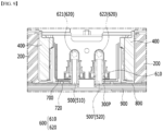
- Fig. 13 is an exploded perspective view of a refrigerant leakage preventive structure of a battery pack according to one embodiment of the present disclosure.
- the cooling port 500 may be located on the lower cover opening 710. More specifically, the cooling port 500 may be formed on the module frame protrusion part 211 so as to pass through the inside of the lower cover opening 710 from the lower side to the upper side. Through this, the refrigerant leaked from the cooling port 500, the connection port 610 connected thereto, and the pack refrigerant tubes 620 can be guided to the lower space S through the lower cover opening 710.
- the cooling port 500 formed in one battery module and the cooling port 500' formed in another battery module are disposed so as to face each other, the lower cover opening 710 is formed in plural numbers, and the two cooling ports 500 and 500' disposed so as to face each other may be located together on one lower cover opening among the plurality of the lower cover openings 710. Thereby, the refrigerant leaked from the two cooling ports 500 and 500' facing each other and located adjacent to each other can be guided to the lower space S at once.
- the module tray 800 includes a module tray opening 810, and the cooling port 500 may be located on the module tray opening 810. At this time, the lower cover opening 710 may be connected to a space S formed between the module tray 800 and the lower housing 900 through the module tray opening 810.
- the battery pack may further include a module tray gasket 820 formed between the module tray 800 and the lower housing 900.
- the module tray 800 is integrally formed along the outer edge portion of each of the plurality of battery modules 100, and the module tray gasket 820 may be formed along an outer edge portion of the module tray 800.
- the module tray gasket 820 can seal between the module tray 800 and the lower housing 900. Thereby, the refrigerant flowing into the space S between the module tray 800 and the lower housing 900 can be prevented from leaking to the outside.
- the battery pack may further include a lower cover gasket 720 formed between the pack refrigerant tube lower cover 700 and the module tray 800.
- the lower cover gasket 720 may be formed outside the lower cover opening 710 and the module tray opening 810.
- the lower cover gasket 720 can seal between the pack refrigerant tube lower cover 700 and the module tray 800.
- the lower cover gasket 720 seals between the module tray 800 and the pack refrigerant tube lower cover 700, and the refrigerant passing through the lower cover opening 710 can pass through the module tray opening 810 and flow in a space S between the module tray 800 and the lower housing 900 without leakage.
- the battery pack may further include a pack refrigerant tube upper cover 740 for covering the upper part of the pack refrigerant tube assembly 600.
- the pack refrigerant tube upper cover 740 may physically protect the pack refrigerant tube assembly 600 from external impact together with the pack refrigerant tube lower cover 700 .
- the battery pack according to embodiments of the present disclosure described above can have a structure in which one or more of the battery modules according to the present embodiment are gathered, and packed together with a battery management system (BMS) and a cooling device that control and manage battery's temperature, voltage, etc.
- BMS battery management system
- the battery pack can be applied to various devices.
- a device may be applied to a vehicle means such as an electric bicycle, an electric vehicle, or a hybrid vehicle, but the present disclosure is not limited thereto, and is applicable to various devices that can use a battery module, which also belongs to the scope of the present disclosure.
Landscapes
- Chemical & Material Sciences (AREA)
- Chemical Kinetics & Catalysis (AREA)
- Electrochemistry (AREA)
- General Chemical & Material Sciences (AREA)
- Engineering & Computer Science (AREA)
- Manufacturing & Machinery (AREA)
- Secondary Cells (AREA)
- Battery Mounting, Suspending (AREA)
Applications Claiming Priority (2)
| Application Number | Priority Date | Filing Date | Title |
|---|---|---|---|
| KR1020200051168A KR102821616B1 (ko) | 2020-04-28 | 2020-04-28 | 전지 팩 및 이를 포함하는 디바이스 |
| PCT/KR2021/004054 WO2021221324A1 (ko) | 2020-04-28 | 2021-04-01 | 전지 팩 및 이를 포함하는 디바이스 |
Publications (3)
| Publication Number | Publication Date |
|---|---|
| EP4020672A1 EP4020672A1 (en) | 2022-06-29 |
| EP4020672A4 EP4020672A4 (en) | 2022-12-28 |
| EP4020672B1 true EP4020672B1 (en) | 2024-01-31 |
Family
ID=78374182
Family Applications (1)
| Application Number | Title | Priority Date | Filing Date |
|---|---|---|---|
| EP21796245.5A Active EP4020672B1 (en) | 2020-04-28 | 2021-04-01 | Battery pack and device including same |
Country Status (9)
| Country | Link |
|---|---|
| US (1) | US12261278B2 (pl) |
| EP (1) | EP4020672B1 (pl) |
| JP (1) | JP7278480B2 (pl) |
| KR (1) | KR102821616B1 (pl) |
| CN (1) | CN114514649B (pl) |
| ES (1) | ES2972180T3 (pl) |
| HU (1) | HUE065498T2 (pl) |
| PL (1) | PL4020672T3 (pl) |
| WO (1) | WO2021221324A1 (pl) |
Families Citing this family (3)
| Publication number | Priority date | Publication date | Assignee | Title |
|---|---|---|---|---|
| KR20240092302A (ko) | 2022-12-14 | 2024-06-24 | 에스케이온 주식회사 | 배터리팩 |
| KR20250175644A (ko) * | 2024-06-10 | 2025-12-17 | 주식회사 엘지에너지솔루션 | 배터리팩 케이스 및 이를 포함하는 배터리팩, 차량 |
| CN120767484B (zh) * | 2025-09-04 | 2025-11-18 | 苏州州伊信息科技有限公司 | 一种高效散热的新能源电池包 |
Family Cites Families (28)
| Publication number | Priority date | Publication date | Assignee | Title |
|---|---|---|---|---|
| KR101029838B1 (ko) * | 2007-06-28 | 2011-04-15 | 주식회사 엘지화학 | 냉각 효율이 향상된 중대형 전지팩 |
| KR101112442B1 (ko) | 2008-10-14 | 2012-02-20 | 주식회사 엘지화학 | 냉각 효율성이 향상된 전지모듈 어셈블리 |
| KR101218751B1 (ko) * | 2010-01-06 | 2013-01-07 | 주식회사 엘지화학 | 냉각 효율성이 향상된 중대형 전지팩 |
| JP5434662B2 (ja) | 2010-02-23 | 2014-03-05 | 三菱自動車工業株式会社 | 車両用バッテリユニットの排水構造 |
| US9548476B2 (en) | 2010-12-20 | 2017-01-17 | Samsung Sdi Co., Ltd. | Multi-cell battery module with integral cooling and assembly aids |
| JP5691992B2 (ja) | 2011-10-18 | 2015-04-01 | 三菱自動車工業株式会社 | 電動車両のバッテリパック搭載構造 |
| JP2014026825A (ja) | 2012-07-26 | 2014-02-06 | Mitsubishi Motors Corp | バッテリ冷却装置 |
| JP6096027B2 (ja) * | 2013-03-27 | 2017-03-15 | 三洋電機株式会社 | 車両用のバッテリシステム及びバッテリシステムを備える電動車両 |
| KR101579483B1 (ko) * | 2014-02-25 | 2015-12-22 | 엘지전자 주식회사 | 배터리팩 |
| JP6376378B2 (ja) | 2014-06-20 | 2018-08-22 | 株式会社Ihi | 蓄電池ユニット |
| US9627724B2 (en) | 2014-12-04 | 2017-04-18 | Lg Chem, Ltd. | Battery pack having a cooling plate assembly |
| KR102253786B1 (ko) * | 2016-10-06 | 2021-05-20 | 주식회사 엘지화학 | 히트 싱크가 일체형으로 결합된 모듈 케이스를 포함하는 전지모듈 |
| US10601088B2 (en) | 2016-10-28 | 2020-03-24 | Tiveni Mergeco, Inc. | Battery module endplate with sealed hole for cooling tube connection |
| KR102196263B1 (ko) | 2016-11-30 | 2020-12-29 | 주식회사 엘지화학 | 액상 냉매 사용에 대해 안정성이 향상된 냉각 구조를 가지는 전지팩 |
| KR102065099B1 (ko) * | 2017-04-04 | 2020-01-10 | 주식회사 엘지화학 | 크래쉬 빔과 배수 구조를 갖는 배터리 팩 |
| KR102172517B1 (ko) | 2017-04-04 | 2020-10-30 | 주식회사 엘지화학 | 크래쉬 빔 구조를 갖는 배터리 팩 |
| KR102050025B1 (ko) * | 2017-09-04 | 2020-01-08 | 주식회사 엘지화학 | 냉각수 직접 접촉 냉각 방식의 배터리 팩 |
| KR20190032843A (ko) * | 2017-09-20 | 2019-03-28 | 에스케이이노베이션 주식회사 | 이차 전지용 배터리 모듈 및 이를 포함하는 배터리 팩 |
| KR102273195B1 (ko) | 2017-12-27 | 2021-07-05 | 주식회사 엘지에너지솔루션 | 개선된 냉각 구조를 갖는 배터리 모듈 |
| CN208127374U (zh) | 2018-04-02 | 2018-11-20 | 东莞市迈泰热传科技有限公司 | 一种用于保护电池的托盘结构 |
| JP6729625B2 (ja) | 2018-04-06 | 2020-07-22 | トヨタ自動車株式会社 | 蓄電装置 |
| KR102372348B1 (ko) * | 2018-06-08 | 2022-03-07 | 주식회사 엘지에너지솔루션 | 개선된 냉각 구조를 갖는 배터리 모듈 |
| KR102655349B1 (ko) | 2018-06-28 | 2024-04-05 | 에스케이온 주식회사 | 냉각장치를 구비한 배터리 팩 |
| CN208400902U (zh) | 2018-07-02 | 2019-01-18 | 深圳市欣旺达综合能源服务有限公司 | 新型储能电池包及其壳体框架 |
| KR20200020482A (ko) | 2018-08-17 | 2020-02-26 | 주식회사 동희산업 | 차량용 알루미늄 배터리 케이스 |
| KR102373774B1 (ko) * | 2018-08-21 | 2022-03-14 | 에스케이온 주식회사 | 배터리 모듈 및 이를 포함하는 배터리 팩 |
| KR102640329B1 (ko) | 2018-10-19 | 2024-02-22 | 삼성에스디아이 주식회사 | 배터리 모듈 |
| US11431056B2 (en) * | 2019-11-13 | 2022-08-30 | Ford Global Technologies, Llc | Systematic layouts for electrified vehicle traction battery packs |
-
2020
- 2020-04-28 KR KR1020200051168A patent/KR102821616B1/ko active Active
-
2021
- 2021-04-01 JP JP2022519316A patent/JP7278480B2/ja active Active
- 2021-04-01 ES ES21796245T patent/ES2972180T3/es active Active
- 2021-04-01 EP EP21796245.5A patent/EP4020672B1/en active Active
- 2021-04-01 US US17/767,156 patent/US12261278B2/en active Active
- 2021-04-01 HU HUE21796245A patent/HUE065498T2/hu unknown
- 2021-04-01 PL PL21796245.5T patent/PL4020672T3/pl unknown
- 2021-04-01 WO PCT/KR2021/004054 patent/WO2021221324A1/ko not_active Ceased
- 2021-04-01 CN CN202180005486.6A patent/CN114514649B/zh active Active
Also Published As
| Publication number | Publication date |
|---|---|
| ES2972180T3 (es) | 2024-06-11 |
| JP7278480B2 (ja) | 2023-05-19 |
| EP4020672A4 (en) | 2022-12-28 |
| US20220376325A1 (en) | 2022-11-24 |
| EP4020672A1 (en) | 2022-06-29 |
| CN114514649B (zh) | 2024-01-05 |
| HUE065498T2 (hu) | 2024-05-28 |
| PL4020672T3 (pl) | 2024-04-15 |
| KR102821616B1 (ko) | 2025-06-16 |
| WO2021221324A1 (ko) | 2021-11-04 |
| JP2022549704A (ja) | 2022-11-28 |
| KR20210132817A (ko) | 2021-11-05 |
| US12261278B2 (en) | 2025-03-25 |
| CN114514649A (zh) | 2022-05-17 |
Similar Documents
| Publication | Publication Date | Title |
|---|---|---|
| EP4095986B1 (en) | Battery pack and device including the same | |
| EP4016703A1 (en) | Battery module and battery pack including same | |
| US12567659B2 (en) | Battery pack and device including the same | |
| US12283678B2 (en) | Battery module and battery pack including the same | |
| EP4184666B1 (en) | Battery pack and device including the same | |
| EP4228061B1 (en) | Battery pack and device including the same | |
| EP4020672B1 (en) | Battery pack and device including same | |
| EP4266457A1 (en) | Battery module and battery pack comprising same | |
| US12592424B2 (en) | Battery module and battery pack including the same | |
| EP4181275B1 (en) | Battery module and battery pack including same | |
| EP4040577A1 (en) | Battery pack and device including same | |
| EP4266456A1 (en) | Battery module and battery pack including same | |
| EP4037077A1 (en) | Battery pack and device including same | |
| EP4261985A1 (en) | Battery pack and device including same | |
| KR20210133543A (ko) | 전지 모듈 및 이를 포함하는 전지 팩 | |
| EP4175020A1 (en) | Battery module and battery pack including same | |
| KR20250043063A (ko) | 전지팩 및 이를 포함하는 디바이스 |
Legal Events
| Date | Code | Title | Description |
|---|---|---|---|
| STAA | Information on the status of an ep patent application or granted ep patent |
Free format text: STATUS: THE INTERNATIONAL PUBLICATION HAS BEEN MADE |
|
| PUAI | Public reference made under article 153(3) epc to a published international application that has entered the european phase |
Free format text: ORIGINAL CODE: 0009012 |
|
| STAA | Information on the status of an ep patent application or granted ep patent |
Free format text: STATUS: REQUEST FOR EXAMINATION WAS MADE |
|
| 17P | Request for examination filed |
Effective date: 20220325 |
|
| AK | Designated contracting states |
Kind code of ref document: A1 Designated state(s): AL AT BE BG CH CY CZ DE DK EE ES FI FR GB GR HR HU IE IS IT LI LT LU LV MC MK MT NL NO PL PT RO RS SE SI SK SM TR |
|
| A4 | Supplementary search report drawn up and despatched |
Effective date: 20221124 |
|
| RIC1 | Information provided on ipc code assigned before grant |
Ipc: H01M 50/20 20210101ALI20221118BHEP Ipc: H01M 50/24 20210101ALI20221118BHEP Ipc: H01M 10/613 20140101ALI20221118BHEP Ipc: H01M 10/6567 20140101ALI20221118BHEP Ipc: H01M 10/6551 20140101ALI20221118BHEP Ipc: H01M 10/6556 20140101AFI20221118BHEP |
|
| DAV | Request for validation of the european patent (deleted) | ||
| DAX | Request for extension of the european patent (deleted) | ||
| GRAP | Despatch of communication of intention to grant a patent |
Free format text: ORIGINAL CODE: EPIDOSNIGR1 |
|
| STAA | Information on the status of an ep patent application or granted ep patent |
Free format text: STATUS: GRANT OF PATENT IS INTENDED |
|
| INTG | Intention to grant announced |
Effective date: 20230823 |
|
| P01 | Opt-out of the competence of the unified patent court (upc) registered |
Effective date: 20230831 |
|
| GRAS | Grant fee paid |
Free format text: ORIGINAL CODE: EPIDOSNIGR3 |
|
| GRAA | (expected) grant |
Free format text: ORIGINAL CODE: 0009210 |
|
| STAA | Information on the status of an ep patent application or granted ep patent |
Free format text: STATUS: THE PATENT HAS BEEN GRANTED |
|
| AK | Designated contracting states |
Kind code of ref document: B1 Designated state(s): AL AT BE BG CH CY CZ DE DK EE ES FI FR GB GR HR HU IE IS IT LI LT LU LV MC MK MT NL NO PL PT RO RS SE SI SK SM TR |
|
| REG | Reference to a national code |
Ref country code: GB Ref legal event code: FG4D Ref country code: CH Ref legal event code: EP |
|
| REG | Reference to a national code |
Ref country code: DE Ref legal event code: R096 Ref document number: 602021009092 Country of ref document: DE |
|
| REG | Reference to a national code |
Ref country code: IE Ref legal event code: FG4D |
|
| REG | Reference to a national code |
Ref country code: SE Ref legal event code: TRGR |
|
| REG | Reference to a national code |
Ref country code: LT Ref legal event code: MG9D |
|
| REG | Reference to a national code |
Ref country code: HU Ref legal event code: AG4A Ref document number: E065498 Country of ref document: HU |
|
| REG | Reference to a national code |
Ref country code: NL Ref legal event code: MP Effective date: 20240131 |
|
| REG | Reference to a national code |
Ref country code: ES Ref legal event code: FG2A Ref document number: 2972180 Country of ref document: ES Kind code of ref document: T3 Effective date: 20240611 |
|
| PG25 | Lapsed in a contracting state [announced via postgrant information from national office to epo] |
Ref country code: IS Free format text: LAPSE BECAUSE OF FAILURE TO SUBMIT A TRANSLATION OF THE DESCRIPTION OR TO PAY THE FEE WITHIN THE PRESCRIBED TIME-LIMIT Effective date: 20240531 |
|
| PG25 | Lapsed in a contracting state [announced via postgrant information from national office to epo] |
Ref country code: LT Free format text: LAPSE BECAUSE OF FAILURE TO SUBMIT A TRANSLATION OF THE DESCRIPTION OR TO PAY THE FEE WITHIN THE PRESCRIBED TIME-LIMIT Effective date: 20240131 |
|
| PG25 | Lapsed in a contracting state [announced via postgrant information from national office to epo] |
Ref country code: GR Free format text: LAPSE BECAUSE OF FAILURE TO SUBMIT A TRANSLATION OF THE DESCRIPTION OR TO PAY THE FEE WITHIN THE PRESCRIBED TIME-LIMIT Effective date: 20240501 |
|
| REG | Reference to a national code |
Ref country code: AT Ref legal event code: MK05 Ref document number: 1654483 Country of ref document: AT Kind code of ref document: T Effective date: 20240131 |
|
| PG25 | Lapsed in a contracting state [announced via postgrant information from national office to epo] |
Ref country code: HR Free format text: LAPSE BECAUSE OF FAILURE TO SUBMIT A TRANSLATION OF THE DESCRIPTION OR TO PAY THE FEE WITHIN THE PRESCRIBED TIME-LIMIT Effective date: 20240131 Ref country code: RS Free format text: LAPSE BECAUSE OF FAILURE TO SUBMIT A TRANSLATION OF THE DESCRIPTION OR TO PAY THE FEE WITHIN THE PRESCRIBED TIME-LIMIT Effective date: 20240430 Ref country code: NL Free format text: LAPSE BECAUSE OF FAILURE TO SUBMIT A TRANSLATION OF THE DESCRIPTION OR TO PAY THE FEE WITHIN THE PRESCRIBED TIME-LIMIT Effective date: 20240131 |
|
| PG25 | Lapsed in a contracting state [announced via postgrant information from national office to epo] |
Ref country code: AT Free format text: LAPSE BECAUSE OF FAILURE TO SUBMIT A TRANSLATION OF THE DESCRIPTION OR TO PAY THE FEE WITHIN THE PRESCRIBED TIME-LIMIT Effective date: 20240131 |
|
| PG25 | Lapsed in a contracting state [announced via postgrant information from national office to epo] |
Ref country code: RS Free format text: LAPSE BECAUSE OF FAILURE TO SUBMIT A TRANSLATION OF THE DESCRIPTION OR TO PAY THE FEE WITHIN THE PRESCRIBED TIME-LIMIT Effective date: 20240430 Ref country code: NO Free format text: LAPSE BECAUSE OF FAILURE TO SUBMIT A TRANSLATION OF THE DESCRIPTION OR TO PAY THE FEE WITHIN THE PRESCRIBED TIME-LIMIT Effective date: 20240430 Ref country code: NL Free format text: LAPSE BECAUSE OF FAILURE TO SUBMIT A TRANSLATION OF THE DESCRIPTION OR TO PAY THE FEE WITHIN THE PRESCRIBED TIME-LIMIT Effective date: 20240131 Ref country code: LT Free format text: LAPSE BECAUSE OF FAILURE TO SUBMIT A TRANSLATION OF THE DESCRIPTION OR TO PAY THE FEE WITHIN THE PRESCRIBED TIME-LIMIT Effective date: 20240131 Ref country code: IS Free format text: LAPSE BECAUSE OF FAILURE TO SUBMIT A TRANSLATION OF THE DESCRIPTION OR TO PAY THE FEE WITHIN THE PRESCRIBED TIME-LIMIT Effective date: 20240531 Ref country code: HR Free format text: LAPSE BECAUSE OF FAILURE TO SUBMIT A TRANSLATION OF THE DESCRIPTION OR TO PAY THE FEE WITHIN THE PRESCRIBED TIME-LIMIT Effective date: 20240131 Ref country code: GR Free format text: LAPSE BECAUSE OF FAILURE TO SUBMIT A TRANSLATION OF THE DESCRIPTION OR TO PAY THE FEE WITHIN THE PRESCRIBED TIME-LIMIT Effective date: 20240501 Ref country code: FI Free format text: LAPSE BECAUSE OF FAILURE TO SUBMIT A TRANSLATION OF THE DESCRIPTION OR TO PAY THE FEE WITHIN THE PRESCRIBED TIME-LIMIT Effective date: 20240131 Ref country code: BG Free format text: LAPSE BECAUSE OF FAILURE TO SUBMIT A TRANSLATION OF THE DESCRIPTION OR TO PAY THE FEE WITHIN THE PRESCRIBED TIME-LIMIT Effective date: 20240131 Ref country code: AT Free format text: LAPSE BECAUSE OF FAILURE TO SUBMIT A TRANSLATION OF THE DESCRIPTION OR TO PAY THE FEE WITHIN THE PRESCRIBED TIME-LIMIT Effective date: 20240131 |
|
| PG25 | Lapsed in a contracting state [announced via postgrant information from national office to epo] |
Ref country code: PT Free format text: LAPSE BECAUSE OF FAILURE TO SUBMIT A TRANSLATION OF THE DESCRIPTION OR TO PAY THE FEE WITHIN THE PRESCRIBED TIME-LIMIT Effective date: 20240531 |
|
| PG25 | Lapsed in a contracting state [announced via postgrant information from national office to epo] |
Ref country code: PT Free format text: LAPSE BECAUSE OF FAILURE TO SUBMIT A TRANSLATION OF THE DESCRIPTION OR TO PAY THE FEE WITHIN THE PRESCRIBED TIME-LIMIT Effective date: 20240531 Ref country code: LV Free format text: LAPSE BECAUSE OF FAILURE TO SUBMIT A TRANSLATION OF THE DESCRIPTION OR TO PAY THE FEE WITHIN THE PRESCRIBED TIME-LIMIT Effective date: 20240131 |
|
| PG25 | Lapsed in a contracting state [announced via postgrant information from national office to epo] |
Ref country code: DK Free format text: LAPSE BECAUSE OF FAILURE TO SUBMIT A TRANSLATION OF THE DESCRIPTION OR TO PAY THE FEE WITHIN THE PRESCRIBED TIME-LIMIT Effective date: 20240131 |
|
| PG25 | Lapsed in a contracting state [announced via postgrant information from national office to epo] |
Ref country code: SM Free format text: LAPSE BECAUSE OF FAILURE TO SUBMIT A TRANSLATION OF THE DESCRIPTION OR TO PAY THE FEE WITHIN THE PRESCRIBED TIME-LIMIT Effective date: 20240131 |
|
| PG25 | Lapsed in a contracting state [announced via postgrant information from national office to epo] |
Ref country code: CZ Free format text: LAPSE BECAUSE OF FAILURE TO SUBMIT A TRANSLATION OF THE DESCRIPTION OR TO PAY THE FEE WITHIN THE PRESCRIBED TIME-LIMIT Effective date: 20240131 Ref country code: EE Free format text: LAPSE BECAUSE OF FAILURE TO SUBMIT A TRANSLATION OF THE DESCRIPTION OR TO PAY THE FEE WITHIN THE PRESCRIBED TIME-LIMIT Effective date: 20240131 |
|
| PG25 | Lapsed in a contracting state [announced via postgrant information from national office to epo] |
Ref country code: SK Free format text: LAPSE BECAUSE OF FAILURE TO SUBMIT A TRANSLATION OF THE DESCRIPTION OR TO PAY THE FEE WITHIN THE PRESCRIBED TIME-LIMIT Effective date: 20240131 |
|
| PG25 | Lapsed in a contracting state [announced via postgrant information from national office to epo] |
Ref country code: SM Free format text: LAPSE BECAUSE OF FAILURE TO SUBMIT A TRANSLATION OF THE DESCRIPTION OR TO PAY THE FEE WITHIN THE PRESCRIBED TIME-LIMIT Effective date: 20240131 Ref country code: SK Free format text: LAPSE BECAUSE OF FAILURE TO SUBMIT A TRANSLATION OF THE DESCRIPTION OR TO PAY THE FEE WITHIN THE PRESCRIBED TIME-LIMIT Effective date: 20240131 Ref country code: RO Free format text: LAPSE BECAUSE OF FAILURE TO SUBMIT A TRANSLATION OF THE DESCRIPTION OR TO PAY THE FEE WITHIN THE PRESCRIBED TIME-LIMIT Effective date: 20240131 Ref country code: EE Free format text: LAPSE BECAUSE OF FAILURE TO SUBMIT A TRANSLATION OF THE DESCRIPTION OR TO PAY THE FEE WITHIN THE PRESCRIBED TIME-LIMIT Effective date: 20240131 Ref country code: DK Free format text: LAPSE BECAUSE OF FAILURE TO SUBMIT A TRANSLATION OF THE DESCRIPTION OR TO PAY THE FEE WITHIN THE PRESCRIBED TIME-LIMIT Effective date: 20240131 Ref country code: CZ Free format text: LAPSE BECAUSE OF FAILURE TO SUBMIT A TRANSLATION OF THE DESCRIPTION OR TO PAY THE FEE WITHIN THE PRESCRIBED TIME-LIMIT Effective date: 20240131 |
|
| REG | Reference to a national code |
Ref country code: DE Ref legal event code: R097 Ref document number: 602021009092 Country of ref document: DE |
|
| PG25 | Lapsed in a contracting state [announced via postgrant information from national office to epo] |
Ref country code: MC Free format text: LAPSE BECAUSE OF FAILURE TO SUBMIT A TRANSLATION OF THE DESCRIPTION OR TO PAY THE FEE WITHIN THE PRESCRIBED TIME-LIMIT Effective date: 20240131 |
|
| PG25 | Lapsed in a contracting state [announced via postgrant information from national office to epo] |
Ref country code: MC Free format text: LAPSE BECAUSE OF FAILURE TO SUBMIT A TRANSLATION OF THE DESCRIPTION OR TO PAY THE FEE WITHIN THE PRESCRIBED TIME-LIMIT Effective date: 20240131 |
|
| REG | Reference to a national code |
Ref country code: CH Ref legal event code: PL |
|
| PG25 | Lapsed in a contracting state [announced via postgrant information from national office to epo] |
Ref country code: IT Free format text: LAPSE BECAUSE OF FAILURE TO SUBMIT A TRANSLATION OF THE DESCRIPTION OR TO PAY THE FEE WITHIN THE PRESCRIBED TIME-LIMIT Effective date: 20240131 |
|
| PLBE | No opposition filed within time limit |
Free format text: ORIGINAL CODE: 0009261 |
|
| STAA | Information on the status of an ep patent application or granted ep patent |
Free format text: STATUS: NO OPPOSITION FILED WITHIN TIME LIMIT |
|
| PG25 | Lapsed in a contracting state [announced via postgrant information from national office to epo] |
Ref country code: LU Free format text: LAPSE BECAUSE OF NON-PAYMENT OF DUE FEES Effective date: 20240401 |
|
| REG | Reference to a national code |
Ref country code: BE Ref legal event code: MM Effective date: 20240430 |
|
| PG25 | Lapsed in a contracting state [announced via postgrant information from national office to epo] |
Ref country code: LU Free format text: LAPSE BECAUSE OF NON-PAYMENT OF DUE FEES Effective date: 20240401 Ref country code: IT Free format text: LAPSE BECAUSE OF FAILURE TO SUBMIT A TRANSLATION OF THE DESCRIPTION OR TO PAY THE FEE WITHIN THE PRESCRIBED TIME-LIMIT Effective date: 20240131 |
|
| 26N | No opposition filed |
Effective date: 20241101 |
|
| PG25 | Lapsed in a contracting state [announced via postgrant information from national office to epo] |
Ref country code: BE Free format text: LAPSE BECAUSE OF NON-PAYMENT OF DUE FEES Effective date: 20240430 |
|
| PG25 | Lapsed in a contracting state [announced via postgrant information from national office to epo] |
Ref country code: BE Free format text: LAPSE BECAUSE OF NON-PAYMENT OF DUE FEES Effective date: 20240430 Ref country code: CH Free format text: LAPSE BECAUSE OF NON-PAYMENT OF DUE FEES Effective date: 20240430 |
|
| PG25 | Lapsed in a contracting state [announced via postgrant information from national office to epo] |
Ref country code: IE Free format text: LAPSE BECAUSE OF NON-PAYMENT OF DUE FEES Effective date: 20240401 |
|
| PG25 | Lapsed in a contracting state [announced via postgrant information from national office to epo] |
Ref country code: SI Free format text: LAPSE BECAUSE OF FAILURE TO SUBMIT A TRANSLATION OF THE DESCRIPTION OR TO PAY THE FEE WITHIN THE PRESCRIBED TIME-LIMIT Effective date: 20240131 |
|
| PGFP | Annual fee paid to national office [announced via postgrant information from national office to epo] |
Ref country code: PL Payment date: 20250325 Year of fee payment: 5 |
|
| PGFP | Annual fee paid to national office [announced via postgrant information from national office to epo] |
Ref country code: DE Payment date: 20250320 Year of fee payment: 5 |
|
| PGFP | Annual fee paid to national office [announced via postgrant information from national office to epo] |
Ref country code: ES Payment date: 20250516 Year of fee payment: 5 |
|
| PGFP | Annual fee paid to national office [announced via postgrant information from national office to epo] |
Ref country code: HU Payment date: 20250425 Year of fee payment: 5 |
|
| PG25 | Lapsed in a contracting state [announced via postgrant information from national office to epo] |
Ref country code: CY Free format text: LAPSE BECAUSE OF FAILURE TO SUBMIT A TRANSLATION OF THE DESCRIPTION OR TO PAY THE FEE WITHIN THE PRESCRIBED TIME-LIMIT; INVALID AB INITIO Effective date: 20210401 |
|
| PG25 | Lapsed in a contracting state [announced via postgrant information from national office to epo] |
Ref country code: TR Free format text: LAPSE BECAUSE OF FAILURE TO SUBMIT A TRANSLATION OF THE DESCRIPTION OR TO PAY THE FEE WITHIN THE PRESCRIBED TIME-LIMIT Effective date: 20240131 |
|
| PGFP | Annual fee paid to national office [announced via postgrant information from national office to epo] |
Ref country code: SE Payment date: 20260323 Year of fee payment: 6 |
|
| PGFP | Annual fee paid to national office [announced via postgrant information from national office to epo] |
Ref country code: GB Payment date: 20260324 Year of fee payment: 6 |
|
| PGFP | Annual fee paid to national office [announced via postgrant information from national office to epo] |
Ref country code: FR Payment date: 20260323 Year of fee payment: 6 |