EP4020726B1 - Mittellinienstromversorgung - Google Patents
Mittellinienstromversorgung Download PDFInfo
- Publication number
- EP4020726B1 EP4020726B1 EP21212214.7A EP21212214A EP4020726B1 EP 4020726 B1 EP4020726 B1 EP 4020726B1 EP 21212214 A EP21212214 A EP 21212214A EP 4020726 B1 EP4020726 B1 EP 4020726B1
- Authority
- EP
- European Patent Office
- Prior art keywords
- bus bars
- enclosure
- bus
- power line
- rail assembly
- Prior art date
- Legal status (The legal status is an assumption and is not a legal conclusion. Google has not performed a legal analysis and makes no representation as to the accuracy of the status listed.)
- Active
Links
Images


Classifications
-
- H—ELECTRICITY
- H01—ELECTRIC ELEMENTS
- H01R—ELECTRICALLY-CONDUCTIVE CONNECTIONS; STRUCTURAL ASSOCIATIONS OF A PLURALITY OF MUTUALLY-INSULATED ELECTRICAL CONNECTING ELEMENTS; COUPLING DEVICES; CURRENT COLLECTORS
- H01R25/00—Coupling parts adapted for simultaneous co-operation with two or more identical counterparts, e.g. for distributing energy to two or more circuits
- H01R25/14—Rails or bus-bars constructed so that the counterparts can be connected thereto at any point along their length
-
- H—ELECTRICITY
- H02—GENERATION; CONVERSION OR DISTRIBUTION OF ELECTRIC POWER
- H02B—BOARDS, SUBSTATIONS OR SWITCHING ARRANGEMENTS FOR THE SUPPLY OR DISTRIBUTION OF ELECTRIC POWER
- H02B1/00—Frameworks, boards, panels, desks, casings; Details of substations or switching arrangements
- H02B1/015—Boards, panels, desks; Parts thereof or accessories therefor
- H02B1/04—Mounting thereon of switches or of other devices in general, the switch or device having, or being without, casing
- H02B1/056—Mounting on plugboards
-
- H—ELECTRICITY
- H02—GENERATION; CONVERSION OR DISTRIBUTION OF ELECTRIC POWER
- H02G—INSTALLATION OF ELECTRIC CABLES OR LINES, OR OF COMBINED OPTICAL AND ELECTRIC CABLES OR LINES
- H02G5/00—Installations of bus-bars
- H02G5/06—Totally-enclosed installations, e.g. in metal casings
-
- H—ELECTRICITY
- H01—ELECTRIC ELEMENTS
- H01B—CABLES; CONDUCTORS; INSULATORS; SELECTION OF MATERIALS FOR THEIR CONDUCTIVE, INSULATING OR DIELECTRIC PROPERTIES
- H01B7/00—Insulated conductors or cables characterised by their form
- H01B7/02—Disposition of insulation
-
- H—ELECTRICITY
- H01—ELECTRIC ELEMENTS
- H01R—ELECTRICALLY-CONDUCTIVE CONNECTIONS; STRUCTURAL ASSOCIATIONS OF A PLURALITY OF MUTUALLY-INSULATED ELECTRICAL CONNECTING ELEMENTS; COUPLING DEVICES; CURRENT COLLECTORS
- H01R25/00—Coupling parts adapted for simultaneous co-operation with two or more identical counterparts, e.g. for distributing energy to two or more circuits
- H01R25/14—Rails or bus-bars constructed so that the counterparts can be connected thereto at any point along their length
- H01R25/142—Their counterparts
-
- H—ELECTRICITY
- H01—ELECTRIC ELEMENTS
- H01R—ELECTRICALLY-CONDUCTIVE CONNECTIONS; STRUCTURAL ASSOCIATIONS OF A PLURALITY OF MUTUALLY-INSULATED ELECTRICAL CONNECTING ELEMENTS; COUPLING DEVICES; CURRENT COLLECTORS
- H01R25/00—Coupling parts adapted for simultaneous co-operation with two or more identical counterparts, e.g. for distributing energy to two or more circuits
- H01R25/14—Rails or bus-bars constructed so that the counterparts can be connected thereto at any point along their length
- H01R25/145—Details, e.g. end pieces or joints
-
- H—ELECTRICITY
- H02—GENERATION; CONVERSION OR DISTRIBUTION OF ELECTRIC POWER
- H02B—BOARDS, SUBSTATIONS OR SWITCHING ARRANGEMENTS FOR THE SUPPLY OR DISTRIBUTION OF ELECTRIC POWER
- H02B1/00—Frameworks, boards, panels, desks, casings; Details of substations or switching arrangements
- H02B1/20—Bus-bar or other wiring layouts, e.g. in cubicles, in switchyards
- H02B1/205—Bus-bar or other wiring layouts, e.g. in cubicles, in switchyards for connecting electrical apparatus mounted side by side on a rail
Definitions
- the present disclosure relates to an electrical distribution system, and more particularly, to a power line rail assembly for an electrical distribution system such as a load center.
- An electrical panel can include live conductors, such as a power line bus and individual connection points on the bus which are connectable to electrical devices, such as circuit breakers and other equipment, for each branch circuit conductor.
- the branch circuit conductors supply electricity to the various loads such as within a residence.
- a power line rail assembly according to the preamble of independent claim 1 is disclosed in US 3 371 251 A . Further power assemblies are disclosed by US 3 075 039 A and US 9 692 213 B2 .
- a power line rail assembly according to independent claim 1 is provided for an electrical distribution system.
- the branching first and second bus bars each have an elongated portion which extends along a direction of a length of the enclosure and upon which to connect an electrical connector of a branch device through a window from the first or second set.
- the elongated portions of the two branching first bus bars can be separated diagonally from each other along a length of the enclosure, and the elongated portions of the two branching second bus bars can be separated diagonally from each other along a length of the enclosure.
- the elongated portion of the first bus bar of the first pair of bus bars can be substantially parallel to the second bus bar of the second pair of bus bars, and the elongated portion of the first bus bar of the second pair of bus bars can be substantially parallel to the second bus bar of the first pair of bus bars.
- the line bus bar assembly also can have a first end and a second opposite end, the two branching first bus bars can branch out from the first end of the line bus bar assembly, and the two branching second bus bars can branch out from the second end of the line bus bar assembly.
- the first and second line buses can supply voltage at first and second voltages respectively, the line bus bar assembly being configured to supply voltage substantially equal to the sum of the first and second voltages when a 2-pole branch device has a first pole connected to the first line bus and a second pole connected to the second line bus, from a window from one of the top and bottom rows and a window from the other of the top and bottom rows respectively on the first or second set.
- each of the first and second sets on respective sides of the enclosure can have their windows spaced apart according to a pole-spacing of branch devices connectable thereto.
- the first and second line buses can be electrically isolated from each other by dielectric or insulation walls in the enclosure.
- the windows of the enclosure can be finger-safe windows.
- a load center can include two neutral buses, and the power line rail assembly which is arranged between the two neutral buses.
- the load center can further include a plurality of tracks each having a guide rail for guiding a branch device to connect to the first or second line bus through a window of a corresponding top and bottom window pair from the top and bottom rows of windows along the enclosure, the tracks and respective window pairs being spaced apart along the enclosure according to pole-spacing of branch devices connectable thereto.
- the load center can further include at least one branch device having a horizontal line connector (commonly called a jaw) for connecting to one of the first and second bus bars through a window from a top and bottom window pair from the top and bottom rows of windows along the enclosure.
- the at least one branch device can further include a horizontal neutral connector, the at least one branch device configured to connect or disconnect the neutral and line connectors to or from the neutral bus bar and one of the first and second bus bars, respectively, when racking in or racking out the at least one branch device along a track from the plurality of tracks.
- the at least one branch device can further include a spring-loaded pawl (or lever) for engaging a tooth or slot on a track from the plurality of tracks to lock the at least one branch device between the power line rail assembly and the track after the at least one branch device is connected to the power line rail assembly in a racked-in position.
- a spring-loaded pawl or lever
- the enclosure of the power line rail assembly can have a substantially rectangular shape with the first and second sets of windows being located along a length of the enclosure on opposite sides thereof.
- the load center can further include an electronic rail configured to enable communications for one or more branch devices connected to branch circuits powered by the first and/or second bus bars, the electronic rail being connected on top of the enclosure of the power line rail assembly.
- the at least one branch device can also include a communication connector for connecting to a communication port of the electronic rail in a horizontal direction.
- the load center can include: an electronic rail configured to enable communications for one or more branch devices connected to branch circuits powered by the first and/or second bus bars, the electronic rail being connected on top of the enclosure of the power line rail assembly, the electronic rail including a row of communication ports arranged along a length of the electronic rail; at least one branch device having a horizontal line connector for connecting to one of the first and second bus bars through a window from a top and bottom window pair from the top and bottom rows of windows along the enclosure of the power line rail assembly, and a communication connector for connecting to a communication port from the row of communication ports on the electronic rail; and a plurality of tracks each having a guide rail for guiding the at least one branch device to connect to the first or second line bus through a window of a corresponding top and bottom window pair from the top and bottom rows of windows along the enclosure of the power line rail assembly and to connect to a communication port from the row of communication ports on the electronic rail.
- the tracks, respective window pairs and communication ports are spaced apart along the enclosure according to pole-
- the present disclosure is directed to a power line rail assembly (or “power line rail”) for an electrical distribution system, such as a center line load center or panelboard (hereinafter “load center”), which employs two separate line buses each having two branching bus bars.
- the branching bus bars of the line buses are configured in an X-formation or -structure (hereinafter “X-formation”) to supply line power to one or more branch devices connected thereto from either sides (e.g., Left side or Right side) of the electrical distribution system.
- the branch devices can include circuit breakers, switches or other protective or monitoring branch devices connectable at the origin of a branch circuit(s).
- the power line rail assembly includes an enclosure, arranged along a center of the electrical distribution system, for housing the bus bars of the line buses.
- the enclosure includes a plurality of windows (e.g., windows, openings, slots, etc.) on opposite sides of the enclosure to allow connection of branch devices to the two line buses therein, from either sides of the electrical distribution system.
- the windows can be spaced apart along the enclosure according to the pole-spacing of the branch devices connectable thereto.
- the electrical distribution system can further include a track system having a plurality of tracks, on opposite sides of the enclosure, for guiding each pole of a branch device to connect to one of the line buses through a respective window on the enclosure.
- the windows and tracks can be arranged on both sides of the electrical distribution system according to the pole-spacing of branch devices connectable thereto, thereby providing a track and associated windows for each pole of a device for connection to a conductor of either of the two line buses.
- the spacing for the tracks and windows are configured to match the spacing of a pole of a connectable branch device (e.g., a width or approximate width of branch device).
- the X-formation of the bus bars of the line buses allows balanced current loading of two line buses (e.g., Line 1 and Line 2) even when using single-pole (also referred to as "one-pole") branch device since Right-side branch devices may access one line and Left-side branch devices may access the other line.
- Such a formation also allows a single-pole branch device to access both lines if desired (e.g., a voltage monitoring device, a surge protective device, etc.).
- the two-dimensional power bus geometry can significantly simplify manufacturing. For example, no additional cutting or forming of bus material may be required. It can also minimizes "off all" wasted raw stock due to cutting.
- the power line rail is able to stand alone as a subassembly. It can house all the necessary parts to create the insulation and conductors to deliver power to every branch device.
- a ratchet locking system can also be provided to lock the branch device to the load center when the branch device is connected to the power line rail assembly.
- the branch device can include a spring-loaded pawl for engaging a teeth/slot on the track.
- the track can include a track T slot and a dovetail rail to prevent device movement in all directions except one direction, and then a ratchet can take away that final direction of movement.
- the track and pawl together can create the ratchet function.
- the ratchet will "lock" the branch device in an installed position, when the branch device is connected to the power line rail assembly along a track of the load center and the pawl of the branch device is engaged to a tooth/slot on the track.
- a screwdriver tool can be used to release the ratchet using the teeth/slots on the track when the pawl is released from the track.
- Such a lock configuration can prevent accidental device removal, and can facilitate rack in and rack out of branch devices along the tracks of the load center.
- an electronic rail assembly (also referred to as “electronic rail”) can be provided, which is connectable over the enclosure of the power line rail assembly.
- the electronic rail subassembly can include communication components, such as processor(s), communication line(s), connector(s)/interface(s) for branch devices, wireline/wireless transceiver(s), etc. which are housed in a housing, and can stand alone as a subassembly or unit.
- the electronic rail assembly can house all the necessary parts to create the insulation, PCBAs, and connectors to centrally connect to branch devices.
- the electronic rail assembly can connect to the cloud for electronic purposes (e.g., monitoring, load control, firmware upgrades, etc.), can also provide a user interface (UI) to users since it can be configured to protrude or extend through a panel cover of a load center.
- the electronic rail assembly can sit on top of the power bus rail assembly, and can be removed and replaced easily (e.g., when malfunctioning) without a major teardown of the panel.
- the electronic rail assembly can provide high-speed communication link between devices, like the branch circuit breakers and a main circuit breaker, which can enable among other things, hybrid switching, main-to-branch circuit breaker interrupting coordination, load shedding, counterfeit protection handshake, and other coordinated operations by or between devices.
- the electronic rail assembly can also act as a circuit breaker electronic trip unit and do many of the protection calculations and decisions on fault protection.
- the electronic rail assembly also can deliver low voltage power to the branch device electronics to eliminate unique power supplies located inside each branch device.
- the various operations enabled by the electronic rail assembly can be controlled or performed by the processor(s) of the electronic rail assembly.
- the connector configurations on the branch devices can also be improved when using a two-line bus assembly with the X-formation described herein.
- the branch device can employ a connector, such as a jaw-type connector, with an jaw orientation that allows an easier and more secure installation direction having increased mechanical advantage for both installing and removing devices with the use of a tool (e.g., a screwdriver or the like). It can allow the power connection to be made in the same direction of movement as the electronic/communication connections of the electronic rail assembly.
- the power line rail assembly can be finger-safe, by combining the simple bus bars and the insulation enclosure (e.g., enclosure, case, housing, etc.).
- the enclosure can include small windows in the insulation enclosure, which are configured with a size or shape to allow a branch device connector (e.g., jaws or jaw connector or other electrical connector) to pass through, but nothing larger such as an average adult-sized finger.
- a branch device connector e.g., jaws or jaw connector or other electrical connector
- the center line load center with the power line rail assembly and electronic rail of the present disclosure can provide communications connections to each or every pole space, as well as better branch device alignment, better branch device retention, easier installation and removal, fewer shock hazards, and can utilize lower cost and simpler bus bar designs.
- Figs. 1 and 2 show a portion of an example electrical distribution system, such as an example load center 100 with a housing 102 without and with a front cover 104, respectively.
- the housing 102 houses components of the load center 100 therein.
- the load center 100 includes two neutral buses 120 and a power line rail assembly 150, which extends along a center-line of the load center 100 between the two neutral buses 120.
- the power line rail assembly 150 includes two separate line buses, namely a first line bus 152 and a second line bus 154, which have conductors to supply power at the same or different voltages (e.g., 120V, 240V, etc.).
- the conductors of the power line rail assembly 150 include two branching bus bars for each line bus 152, 154 and can be connected to receive power from a mains supply or other upstream power source.
- the power line rail assembly 150 has the bus bars of the line buses 152 and 154 arranged in an X-formation or -structure ("X-formation") to allow a branch device to be connected to the first line bus 152 or the second line bus 154 from either sides of a finger-safe enclosure of the power line rail assembly 150, such as from a Left side or Right side of the load center 100.
- the load center 100 can include a track system having a plurality of tracks 170, on opposite sides of the power line rail assembly 150, for each pole of a branch device connectable thereto.
- Each track 170 can include a guide rail 172 for a pole of a branch device, and a plurality of teeth/slots of a ratchet lock system for locking the branch device when connected to a conductor of the power line rail assembly 150.
- a plurality of branch devices such as for example, circuit breakers (e.g., miniature circuit breakers (MCB), etc.), can be connected along the power line rail assembly 160.
- the branch devices can include for example a single-pole branch device 190, a two-pole branch device 192 and other branch devices, which are connected to the conductors of the power line rail assembly 150.
- an electronic rail 160 is arranged on the power line rail assembly 150, and includes a housing 162 for housing the components of the electronic rail 160.
- the housing 162 is configured to fit or sit on top of the enclosure of the power line rail assembly 150.
- the electronic rail can be connected to the power line rail assembly 150 using one or more fasteners 162 (e.g., screws).
- the electronic rail 160 can include communication equipment through which communications may be conducted by or with devices connected thereto.
- the communication equipment of the electronic rail 160 can include transceiver(s) for conducting line or wireless communication, communication lines, device connectors/interfaces, a processor(s) for controlling the components and operations of the electronic rail 160 as well as other connected devices in the load center 100, which are housed in a housing 162 (e.g., housing, case, enclosure, etc.).
- the housing 162 can also include windows through which branch devices can be connected to the connectors/interfaces of the electronic rail 160 in order to conduct communications with other devices.
- a part of the electronic rail 160 can extend through an opening on the cover 104.
- Such a configuration may be useful when employing wireless communication, since the wireless transceiver or its antennas may be arranged in a portion of the electronic rail that extends through the cover 104.
- a user interface may also be provided on the extended portion for the user to input commands or setting which can be used to control the operations of the load center and devices connected therein, including branch devices, main circuit breaker and so forth.
- a top portion of the circuit breakers 190 and 192 with their handles also extend through the housing 102 to enable user operation thereof, and filler plates 210 can be used to cover openings without branch devices.
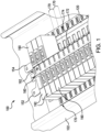
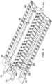
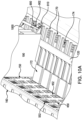
- Figs. 3A , 3B and 4 show an example of the power line rail assembly 150 of Figs. 1 and 2 , without and with an enclosure 400, which is arranged along a center line (or axis) of the load center 100 between two neutral bus lines (or bars) 120.
- the power line rail assembly 150 includes a line bus assembly with conductors, such as the first line bus 152 and the second line bus 154, which can supply power at the same or different voltages to branch devices connected thereto.
- the first line bus 152 includes two branching first bus bars 352A and 352B
- the second line bus includes two branching second bus bars 354A and 354B.
- the bus bars 352A, 352B, 354A, and 354B each have elongated portion, which extends in a lengthwise direction and upon which to connect an electrical connector of a branch device.
- the elongated portions of the branching first bus bars 352A and 352B are diagonally separated from each other and branch out from one end of the power line rail assembly 150; and the elongated portions of the second bus bars 354A and 354B are also diagonally separated from each other and branch out from the other end of the power line rail assembly 150.
- the first bus bar 352A branches out at a height, which is less than the height at which the first bus bar 352B branches out; the second bus bar 354A branches out at a height, which is less than the height at which the second bus bar 354B branches out.
- the first bus bars 352A and 352B (or their elongated portions) and the second bus bars 354A and 354B (or their elongated portions) are separated from each other in an X-formation to provide first and second pairs of separated bus bars for each side, e.g., a Left side and a Right side, of the load center 100.
- the first pair of separated bus bars 352B and 354A has one of the first bus bars 352B positioned over one of the second bus bars 354A
- the second pair of separated bus bars 352A and 354B has the other of the first bus bars 352A positioned under the other of the second bus bars 354B.
- the first and second bus bars 352A, 352B, 354A and 354B (or their elongated portions) are at least substantially parallel/parallel to each other.
- the power line rail assembly 150 includes the enclosure 400 (e.g., housing, case, enclosure, etc.) for housing the conductors of the line bus bar assembly of the power line rail assembly 150.
- the enclosure 400 can be an insulation (or electrically insulated) enclosure, which can be formed of a dielectric or insulation material.
- the enclosure 400 includes first and second sets of windows on opposite sides of the enclosure 400 through which to connect or engage a connector from a device to the first and second pairs of bus bars 352B, 354A and 352A, 354B respectively in the enclosure 400.
- the first set of windows includes a top row of windows 450 ("top windows”) for connecting to the first bus bar 352B and a bottom row of windows 452 ("bottom windows”) for connecting to the second bus bar 354A of the first pair of bus bars.
- the second set of windows on the opposite side of the enclosure 400 can have a similar or same/identical layout as the first set of windows.
- the second set of windows also can include a top row of windows 450 for connecting to the second bus bar 354B and a bottom row of windows 452 for connecting to the first bus bar 352A of the second pair of bus bars.
- the windows 450 and 452 of the first and second sets are arranged along a length of the enclosure 400.
- the windows 450 and 452 also can be finger-safe windows, which can have a size, shape and/or dimension to prevent an average adult sized finger from touching conductors of the assembly 150 through the window, but can allow a connector (e.g., a jaw connector or other electrical connector) of a device to connect to the conductors through the window.
- a connector e.g., a jaw connector or other electrical connector
- the windows 450 and 452 of the first and second sets can have a spacing/pitch along a length of the enclosure 400, which can correspond to a spacing/pitch of the tracks 170 for each pole of a branch device connectable to the power line rail assembly 150.
- Each pair of windows 450 and 452 can thus be aligned and associated with a respective track 170 for receiving a pole of a branch device. Accordingly, the spacing/pitch of pairs of windows 450 and 452 and the tracks 170 along a lengthwise direction can be matched to the pole spacing of branch devices connectable to the power line rail assembly.
- branch devices e.g., 190 and 192
- branch devices can be connected to or disconnected from the power line rail assembly 150 in a safe and orderly fashion from both sides of the load center 100.
- the pitch/spacing of components can correspond to a distance from a center of one component to a center of the next or adjacent component.
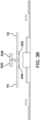
- the enclosure 400 of the power line rail assembly 150 can include one or more fastener holes 458, e.g., at either ends of the enclosure, for securing the electronic rail 160 or its housing 162 to a top of the enclosure 400 using fastener(s) 558 such as screws as shown in Fig. 5A .
- fastener(s) 558 such as screws as shown in Fig. 5A .
- Other types of fasteners or fastening systems can be used to secure the electronic rail 160 to the power line rail assembly 150.
- the top of the enclosure 400 can have a beveled edge (or border) so that the bottom of the housing 162 can sit on top of the enclosure 400.
- the housing 162 of the electronic rail 160 can also include spaced-apart windows 550, each with a communication port 552 (e.g., RJ-type port, USB port, etc.) as shown in Fig. 5B for enabling a branch device to connect its communication components to the electronic rail 160, via a communication connector (e.g., RJ-type connector, USB connector, etc.).
- the communication ports 552 may be spaced apart along the housing 162 to align with associated tracks 170 and associated pairs of windows 450 and 452, and thus, can also have a pitch spacing corresponding to pole-spacing of branch devices connectable to the load center 100.
- the pole-spacing (or pitch spacing) of a branch device can be a width or approximate width of the branch device, such as a width of circuit breakers (e.g., one-inch wide, 25mm wide, or less). Pitch or spacing can be taken from a center line/axis of one device or component to a centerline of an adjacent device or component.
- each of the plurality of tracks 170 on opposite sides of the power line rail assembly 150 can include a guide rail 172 and teeth/slots 174.
- Each guide rail 172 can have a dove tail cross-section for engaging and guiding each pole of a branch device thereon along a horizontal direction. In this way, a branch device can be inserted onto the guide rail 172 to slide towards or away from the power line rail assembly 150 and the electronic rail 160.
- Figs. 6A, 6B and 6C show an example one-pole branch device 190 with a horizontal line connector 692 for horizontally connecting to a conductor of a line bus and a horizontal neutral connector 694 for horizontally connecting to the neutral bus 120, and a communication connector 698 to connect to the electronics rail 160.
- the horizontal line connector 692 can be configured with a desired height to connect to a conductor of a line bus through a top window 450 or bottom window 452 of the power line rail assembly 150 of Figs. 4 and 5 .
- the branch device 190 can include a grooved bottom portion 696, which has a size and shape to engage and slide along the guide rail 172 of one of the tracks 170 in a horizontal direction.
- the portion 696 can have a groove with a dove-tail cross-sectional shape, and the line and neutral connectors 692, 694 can be jaw-type connectors.
- the one-pole branch device 190 can have a width of about 25mm.
- Figs. 7A, 7B and 7C show an example two-pole branch device 192 with two sets of horizontal line and neutral connectors for each pole, and a communication connector 798 to connect to the electronics rail 160, in accordance with an embodiment.
- the branch device 192 has a first set of horizontal line and neutral connectors 792A and 794A respectively for a first pole, and a second set of horizontal line and neutral connectors 792B and 794B respectively for a second pole.
- the horizontal line connector 792A has a height or position to connect to a bottom window 452 of the enclosure 400 (e.g., in Fig. 4 ), and the horizontal line connector 792B has a height or position to connect to a top window 450 of the enclosure.
- the branch device 192 also includes grooved bottom portions 796A and 796B for the first and second poles respectively.
- Each of the grooved bottom portions 796A, 796B has a size and shape to engage and slide along a guide rail 172 of one of the tracks 170 in a horizontal direction.
- the portion 796A, 796B can have a groove with a dove-tail cross-sectional shape, and the line and neutral connectors 792A/B, 794A/B can be jaw-type connectors.
- each pole of the branch device 192 can have a width of about 25mm.
- Fig. 8 shows a cross-sectional view of the load center 100 of Figs. 1 and 2 , including the power rail bus assembly 150 and branch devices (e.g., 190 and 192) connected thereto in accordance with an embodiment.
- branching first bus bars 352A and 352B and branching second bus bars 354A and 354B of the first and second line buses 152 and 154, respectively are arranged in an X-formation to provide first and second pairs of separated bus bars for each side, e.g., a Left side and a Right side, of the load center 100.
- the first pair of separated bus bars 352B and 354A has one of the first bus bars 352B positioned above one of the second bus bars 354A
- the second pair of separated bus bars 352A and 354B has the other of the first bus bars 352A positioned below the other of the second bus bars 354B.
- a one-pole branch device 190 is arranged on a track 170 on a Left side of the load center 100, and has its line connector 692 connected to the second bus bar 354A of the second line bus 154 through a bottom window 452 of the enclosure 400 and its neutral connector 694 connected to the neutral bus 120.
- another one-pole branch device 190 is arranged on a track 170 on a Right side of the load center 100, and has its line connector 692 connected to the first bus bar 352A of the first line bus 152 through a bottom window 452 of the enclosure 400 and its neutral connector 694 connected to the neutral bus 120.
- a one-pole branch device can be connected to either the first line bus 152 or second line bus 154 of the power line rail assembly 150 from either sides of the load center 100.
- a two-pole branch device 192 e.g., in Fig. 7
- the branch device 192 and its branch circuit can be supplied with the combined voltage from the first and second line buses 152 and 154, respectively.
- Figs. 9A, 9B, 9C and 9D show different views of a one-pole branch device 190 (e.g., in Figs. 6A, 6B and 8 ) with a circuit breaker ratchet lock assembly, in accordance with an embodiment.
- the branch device 190 incorporates components of a ratchet lock for locking the branch device 190 into a track 170 when the line and neutral connectors 692, 694 are connected to a conductor on the power line rail assembly 150 and the neutral bus 120, respectively.
- Figs. 9A, 9B, 9C and 9D show different views of a one-pole branch device 190 (e.g., in Figs. 6A, 6B and 8 ) with a circuit breaker ratchet lock assembly, in accordance with an embodiment.
- the branch device 190 incorporates components of a ratchet lock for locking the branch device 190 into a track 170 when the line and neutral connectors 692, 694 are connected to a conductor on
- the branch device 190 can include a bracket 900 for retaining a spring-loaded pawl (or lever), which can pivot along an axis and can be spring-loaded so a tip (or open-end) of the pawl 910 is pointing downwards in a resting position.
- the bracket 900 also includes a space (or opening) 902 between the pawl 910 and a back wall of the branch device 190 or bracket 900.
- the pawl 910 can be engaged to one of the teeth/slots 174 on the track 170 as shown in Figs. 9C and 9D in order to lock the branch device 190 between the track 170 and the power line rail assembly 150.
- the ratchet lock assembly as described herein, may also be employed with multi-pole branch devices which can include one pawl or a pawl for each pole.
- Figs. 10A , 10B and 10C show an example of how to rack-in and rack-out a branch device (e.g., device 190 of Fig. 6 ) on a track 170 from the power line rail assembly 150 of the load center 100 of Figs. 1 and 2 , in accordance with an embodiment.
- a branch device e.g., device 190 of Fig. 6
- each pole of the branch device 190 which in this example is a single-pole device, can be inserted onto a track 170 to move along the guide rail 172 of the track 170.
- the bottom groove 696 of the branch device 190 can be movably engaged to the guide rail 172 of the track 170.
- a flat screwdriver or similar tool 1000 can be extended through the space 902 of the bracket 900 of the branch device 190 to engage one of teeth/slots 174 of the track 170.
- the tool 1000 can be manipulated in one direction as shown in Fig. 10B to rack-in the branch device 190 to connect the line connector 692 to a conductor of the power line rail assembly 150 (via a window 450 or 452) and the neutral connector 694 to the neutral bus 120.
- a communication connector e.g., 698 in Fig. 6C or 798 n Fig. 7C
- the branch device 190 can also be connected to a corresponding communication port 552 on the electronic rail 160 for facilitating communication between branch device(s) and other devices/systems.
- the tool 1000 can be manipulated in the other direction as shown in Fig. 10C to rack-out the branch device 190 to disconnect the line connector 692 from a conductor of the power line rail assembly (via a window 450 or 452), the neutral connector 694 to the neutral bus 120, and other component(s) of the branch device 190 from the load center 100.
- the load center 100 provides a power line bus assembly 150, and if desired, an electronic rail 160 along a center line or axis, which can allow branch devices (and their connectors) to be easily racked-in to and racked out from the conductors and communication components of the load center 100.
- the load center 100 also provides a track system with a ratchet lock assembly as well as finger-safe protection, which can facilitate the connection and disconnection of branch devices in an orderly and safe manner on the load center 100.
Landscapes
- Engineering & Computer Science (AREA)
- Power Engineering (AREA)
- Distribution Board (AREA)
- Patch Boards (AREA)
Claims (18)
- Stromschienenanordnung (150) für ein elektrisches Verteilungssystem, umfassend:eine Leitungssammelschienenanordnung zum Zuführen von elektrischer Energie, wobei die Leitungssammelschienenanordnung Leiter, die einen ersten Leitungsbus (152) und einen separaten zweiten Leitungsbus (154) umfassen, wobei der erste Leitungsbus (152) zwei abzweigende erste Sammelschienen (352A, 352B) umfasst, wobei der zweite Leitungsbus (154) zwei abzweigende zweite Sammelschienen (354A, 354B) umfasst, und ein Gehäuse (400) zum Aufnehmen von Leitern der Leitungssammelschienenanordnung umfasst,dadurch gekennzeichnet, dassdas Gehäuse (400) umfasst:einen ersten und einen zweiten Satz von Fenstern (450, 452) auf gegenüberliegenden Seiten des Gehäuses (400), durch die jeweils das erste (352A, 352B) und das zweite Paar von Sammelschienen (354A, 354B) in dem Gehäuse (400) zu verbinden sind,die erste (352A, 352B) und die zweite Sammelschiene (354A, 354B) in einer X-Formation entlang einer Länge der Leitungssammelschienenanordnung voneinander getrennt sind, um ein erstes und ein zweites Paar von getrennten Sammelschienen bereitzustellen, wobei das erste Paar von getrennten Sammelschienen eine der ersten Sammelschienen (352A, 352B) aufweist, die über einer der zweiten Sammelschienen (354A, 354B) positioniert ist, wobei das zweite Paar von getrennten Sammelschienen die andere der ersten Sammelschienen (352A, 352B) aufweist, die unter der anderen der zweiten Sammelschienen (354A, 354B) positioniert ist,jeder des ersten und des zweiten Satzes von Fenstern (450, 452) eine obere Reihe von Fenstern und eine untere Reihe von Fenstern aufweist, wobei die obere und die untere Reihe entlang einer Länge des Gehäuses (400) angeordnet sind,die obere Reihe von Fenstern des ersten Satzes zum Verbinden mit einer der ersten (352A, 352B) und der zweiten Sammelschiene (354A, 354B) des ersten Paars von getrennten Sammelschienen,die untere Reihe von Fenstern des ersten Satzes zum Verbinden mit der anderen der ersten (352A, 352B) und der zweiten Sammelschiene (354A, 354B) des ersten Paars von getrennten Sammelschienen,die obere Reihe von Fenstern des zweiten Satzes zum Verbinden mit einer der ersten (352A, 352B) und der zweiten Sammelschiene (354A, 354B) des zweiten Paars von getrennten Sammelschienen, unddie untere Reihe von Fenstern des zweiten Satzes zum Verbinden mit der anderen der ersten (352A, 352B) und der zweiten Sammelschiene (354A, 354B) des zweiten Paars von getrennten Sammelschienen.
- Stromschienenanordnung (150) nach Anspruch 1, wobei die abzweigenden ersten (352A, 352B) und zweiten Sammelschienen (354A, 354B) jeweils einen länglichen Abschnitt aufweisen, der sich entlang einer Richtung einer Länge des Gehäuses (400) erstreckt und auf dem ein elektrischer Verbinder einer Abzweigvorrichtung (190, 192) durch ein Fenster von dem ersten oder dem zweiten Satz zu verbinden ist.
- Stromschienenanordnung (150) nach Anspruch 2, wobei die länglichen Abschnitte der zwei abzweigenden ersten Sammelschienen (352A, 352B) entlang einer Länge des Gehäuses (400) diagonal voneinander getrennt sind und die länglichen Abschnitte der zwei abzweigenden zweiten Sammelschienen (354A, 354B) entlang einer Länge des Gehäuses (400) diagonal voneinander getrennt sind.
- Stromschienenanordnung (150) nach einem der Ansprüche 2 oder 3, wobei der längliche Abschnitt der ersten Sammelschiene des ersten Paars von Sammelschienen zumindest im Wesentlichen parallel zu der zweiten Sammelschiene des zweiten Paars von Sammelschienen ist und der längliche Abschnitt der ersten Sammelschiene des zweiten Paars von Sammelschienen zumindest im Wesentlichen parallel zu der zweiten Sammelschiene des ersten Paars von Sammelschienen ist.
- Stromschienenanordnung (150) nach einem der vorhergehenden Ansprüche, wobei die Leitungssammelschienenanordnung ein erstes Ende und ein zweites gegenüberliegendes Ende aufweist, die zwei abzweigenden ersten Sammelschienen (352A, 352B) von dem ersten Ende der Leitungssammelschienenanordnung abzweigen und die zwei abzweigenden zweiten Sammelschienen (354A, 354B) von dem zweiten Ende der Leitungssammelschienenanordnung abzweigen.
- Stromschienenanordnung (150) nach einem der vorhergehenden Ansprüche, wobei der erste und der zweite Leitungsbus eine Spannung bei einer ersten bzw. einer zweiten Spannung zuführen, wobei die Leitungssammelschienenanordnung konfiguriert ist, um eine Spannung, die im Wesentlichen gleich der Summe der ersten und der zweiten Spannung ist, wenn eine 2-polige Abzweigvorrichtung (190, 192) einen ersten Pol, der mit dem ersten Leitungsbus (152) verbunden ist, und einen zweiten Pol, der mit dem zweiten Leitungsbus (154) verbunden ist, aufweist, von einem Fenster von einer der oberen und der unteren Reihe bzw. einem Fenster von der anderen der oberen und der unteren Reihe an dem ersten oder dem zweiten Satz zuzuführen.
- Stromschienenanordnung (150) nach einem der vorhergehenden Ansprüche, wobei die Reihen von jedem des ersten und des zweiten Satzes auf jeweiligen Seiten des Gehäuses (400) ihre Fenster gemäß einem Polabstand von Abzweigvorrichtungen (190, 192), die damit verbindbar sind, voneinander beabstandet aufweisen.
- Stromschienenanordnung (150) nach einem der vorhergehenden Ansprüche, wobei der erste und der zweite Leitungsbus durch dielektrische oder isolierende Wände in dem Gehäuse (400) elektrisch voneinander isoliert sind.
- Stromschienenanordnung (150) nach einem der vorhergehenden Ansprüche, wobei die Fenster des Gehäuses (400) fingersichere Fenster sind.
- Lastzentrum, umfassend:zwei neutrale Busse (120); undeine Stromschienenanordnung (150) nach Anspruch 1, die zwischen den zwei neutralen Bussen (120) angeordnet ist.
- Lastzentrum nach Anspruch 10, ferner umfassend:
eine Vielzahl von Bahnen (170), die jeweils eine Führungsschiene (172) zum Führen einer Abzweigvorrichtung (190, 192) zum Verbinden mit dem ersten (152) oder dem zweiten Leitungsbus (154) durch ein Fenster eines entsprechenden oberen und unteren Fensterpaars von der oberen und der unteren Reihe von Fenstern entlang des Gehäuses (400) der Stromschienenanordnung (150) aufweisen, wobei die Bahnen (170) und jeweiligen Fensterpaare entlang des Gehäuses (400) gemäß dem Polabstand von Abzweigvorrichtungen (190, 192), die damit verbindbar sind, voneinander beabstandet sind. - Lastzentrum nach einem der Ansprüche 10 oder 11, ferner umfassend mindestens eine Abzweigvorrichtung (190, 192) mit einem horizontalen Leitungsverbinder (692, 792) zum Verbinden mit einer der ersten (352A, 352B) und der zweiten Sammelschiene (354A, 354B) durch ein Fenster von einem oberen und unteren Fensterpaar von der oberen und der unteren Reihe von Fenstern entlang des Gehäuses (400) der Stromschienenanordnung (150).
- Lastzentrum nach Anspruch 12, wobei die mindestens eine Abzweigvorrichtung (190, 192) ferner einen horizontalen neutralen Verbinder umfasst, wobei die mindestens eine Abzweigvorrichtung (190, 192) konfiguriert ist, um den neutralen (694, 794) und den Leitungsverbinder (692, 792) mit oder von der neutralen Sammelschiene bzw. einer der ersten (352A, 352B) und der zweiten Sammelschiene (354A, 354B) zu verbinden oder zu trennen, wenn die mindestens eine Abzweigvorrichtung (190, 192) entlang einer Bahn von der Vielzahl von Bahnen (170) ein- oder ausgerückt wird.
- Lastzentrum nach einem der Ansprüche 12 oder 13, wobei die mindestens eine Abzweigvorrichtung (190, 192) ferner eine federbelastete Sperrklinke (910) zum Eingreifen in einen Zahn oder Schlitz (174) auf einer Bahn (170) von der Vielzahl von Bahnen (170) umfasst, um die mindestens eine Abzweigvorrichtung (190, 192) zwischen der Stromschienenanordnung (150) und der Bahn zu verriegeln, nachdem die mindestens eine Abzweigvorrichtung (190, 192) mit der Stromschienenanordnung (150) in einer eingerückten Position verbunden ist.
- Lastzentrum nach einem der Ansprüche 10 bis 14, wobei das Gehäuse (400) der Stromschienenanordnung (150) eine im Wesentlichen rechteckige Form aufweist, wobei der erste und der zweite Satz von Fenstern (450, 452) entlang einer Länge des Gehäuses (400) der Stromschienenanordnung (150) auf gegenüberliegenden Seiten davon angeordnet sind.
- Lastzentrum nach einem der Ansprüche 10 bis 15, ferner umfassend eine elektronische Schiene (160), die konfiguriert ist, um Kommunikationen für eine oder mehrere Abzweigvorrichtungen (190, 192) zu ermöglichen, die mit Abzweigschaltungen verbunden sind, die von der ersten (352A, 352B) und/oder der zweiten Sammelschiene (354A, 354B) mit Leistung versorgt werden, wobei die elektronische Schiene (160) oben auf dem Gehäuse (400) der Stromschienenanordnung (150) verbunden ist.
- Lastzentrum nach Anspruch 16, ferner umfassend mindestens eine Abzweigvorrichtung (190, 192) mit einem horizontalen Leitungsverbinder (692, 792) zum Verbinden mit einer der ersten (352A, 352B) und der zweiten Sammelschiene (354A, 354B) durch ein Fenster von einem oberen und unteren Fensterpaar von der oberen und der unteren Reihe von Fenstern entlang des Gehäuses (400) der Stromschienenanordnung (150), wobei die mindestens eine Abzweigvorrichtung (190, 192) ferner einen Kommunikationsverbinder (698, 798) zum Verbinden mit einem Kommunikationsanschluss der elektronischen Schiene (160) in einer horizontalen Richtung umfasst.
- Lastzentrum nach einem der Ansprüche 10 bis 17, ferner umfassend:eine elektronische Schiene (160), die konfiguriert ist, um Kommunikationen für eine oder mehrere Abzweigvorrichtungen (190, 192) zu ermöglichen, die mit Abzweigschaltungen verbunden sind, die von der ersten (352A, 352B) und/oder der zweiten Sammelschiene (354A, 354B) mit Leistung versorgt werden, wobei die elektronische Schiene (160) oben auf dem Gehäuse (400) der Stromschienenanordnung (150) verbunden ist, wobei die elektronische Schiene (160) eine Reihe von Kommunikationsanschlüssen (552) umfasst, die entlang einer Länge der elektronischen Schiene (160) angeordnet sind,mindestens eine Abzweigvorrichtung (190, 192) mit einem horizontalen Leitungsverbinder (692, 792) zum Verbinden mit einer der ersten (352A, 352B) und der zweiten Sammelschiene (354A, 354B) durch ein Fenster von einem oberen und unteren Fensterpaar von der oberen und der unteren Reihe von Fenstern entlang des Gehäuses (400) der Stromschienenanordnung (150), und einem Kommunikationsverbinder (698, 798) zum Verbinden mit einem Kommunikationsanschluss von der Reihe von Kommunikationsanschlüssen (552) auf der elektronischen Schiene (160); undeine Vielzahl von Bahnen (170), die jeweils eine Führungsschiene (172) zum Führen der mindestens einen Abzweigvorrichtung (190, 192) zum Verbinden mit dem ersten (152) oder dem zweiten Leitungsbus (154) durch ein Fenster eines entsprechenden oberen und unteren Fensterpaars von der oberen und der unteren Reihe von Fenstern entlang des Gehäuses (400) der Stromschienenanordnung (150) und zum Verbinden mit einem Kommunikationsanschluss von der Reihe von Kommunikationsanschlüssen (552) auf der elektronischen Schiene (160) aufweisen,wobei die Bahnen (170), jeweiligen Fensterpaare und Kommunikationsanschlüsse (552) entlang des Gehäuses (400) gemäß einem Polabstand von Abzweigvorrichtungen (190, 192), die damit verbindbar sind, voneinander beabstandet sind.
Applications Claiming Priority (1)
| Application Number | Priority Date | Filing Date | Title |
|---|---|---|---|
| US17/130,241 US11217980B1 (en) | 2020-12-22 | 2020-12-22 | Center line load center |
Publications (2)
| Publication Number | Publication Date |
|---|---|
| EP4020726A1 EP4020726A1 (de) | 2022-06-29 |
| EP4020726B1 true EP4020726B1 (de) | 2025-03-05 |
Family
ID=78821572
Family Applications (1)
| Application Number | Title | Priority Date | Filing Date |
|---|---|---|---|
| EP21212214.7A Active EP4020726B1 (de) | 2020-12-22 | 2021-12-03 | Mittellinienstromversorgung |
Country Status (3)
| Country | Link |
|---|---|
| US (1) | US11217980B1 (de) |
| EP (1) | EP4020726B1 (de) |
| CN (1) | CN114665346A (de) |
Families Citing this family (4)
| Publication number | Priority date | Publication date | Assignee | Title |
|---|---|---|---|---|
| CA221654S (en) * | 2022-11-24 | 2025-03-06 | Osho Ltd | Electrical distribution board |
| CA221652S (en) * | 2022-11-24 | 2025-03-06 | Osho Ltd | Electrical distribution board |
| CA221651S (en) * | 2022-11-24 | 2025-03-06 | Osho Ltd | Electrical distribution board |
| US12560637B2 (en) * | 2024-03-13 | 2026-02-24 | Schneider Electric USA, Inc. | Automatic assessment of electrical unbalance on three-phase loads |
Family Cites Families (24)
| Publication number | Priority date | Publication date | Assignee | Title |
|---|---|---|---|---|
| US2986676A (en) * | 1956-07-30 | 1961-05-30 | Ite Circuit Breaker Ltd | Panel board arrangement for embedded load terminals |
| US2997627A (en) * | 1958-05-29 | 1961-08-22 | Frank Adam Electric Co | Distribution switchboard |
| US3192446A (en) * | 1960-05-16 | 1965-06-29 | Ite Circuit Breaker Ltd | Distribution panel |
| US3075039A (en) * | 1960-07-12 | 1963-01-22 | Murray Mfg Corp | Polyphase load center bus bar mounting |
| US3273022A (en) * | 1963-08-05 | 1966-09-13 | Amalgamated Electric Corp Ltd | Electrical load distribution service centre |
| US3371251A (en) * | 1965-08-16 | 1968-02-27 | Westinghouse Electric Corp | Panel assembly with improved insulating means |
| US3349292A (en) * | 1966-06-01 | 1967-10-24 | Ite Circuit Breaker Ltd | Load center |
| US4720769A (en) * | 1985-02-25 | 1988-01-19 | General Electric Company | Lighting circuit breaker panelboard modular assembly including circuit breaker support mounting brackets |
| US5229922A (en) * | 1991-09-26 | 1993-07-20 | Yazaki Corporation | Electrical junction box with stacked insulating plates and bus-bars with stepped tabs |
| US5343356A (en) * | 1992-12-31 | 1994-08-30 | Siemens Energy & Automation, Inc. | Panelboard |
| US5414590A (en) * | 1993-10-22 | 1995-05-09 | Square D Company | Meter socket assembly and distribution board |
| US6002580A (en) * | 1996-12-09 | 1999-12-14 | Power Distribution Products International | Circuit breaker power distribution panel |
| US6530811B1 (en) * | 1999-06-04 | 2003-03-11 | Astec International Limited | Modular distribution assembly |
| US6122160A (en) * | 1999-08-27 | 2000-09-19 | Telefonaktiebolaget Lm Ericsson | Arrangement for connecting one or more fuses to a distribution unit |
| US6672914B1 (en) * | 2001-07-27 | 2004-01-06 | Emc Corporation | Methods and apparatus for mounting a bus bar assembly |
| US6924721B2 (en) * | 2003-07-14 | 2005-08-02 | Eaton Corporation | Gas segregator barrier for electrical switching apparatus |
| US7298606B2 (en) * | 2004-03-29 | 2007-11-20 | General Electric Company | Apparatus for interfacing remote operated and non-remote operated circuit breakers with an electrical panel |
| US7256984B2 (en) * | 2005-05-10 | 2007-08-14 | Tyco Electronics Power Systems, Inc. | Reconfigurable power distribution panel |
| US7889480B2 (en) * | 2007-08-06 | 2011-02-15 | Abb Inc. | Panelboard |
| US7952026B2 (en) * | 2009-06-22 | 2011-05-31 | Jim Ramsey | Angled stabs for a busway plug in unit |
| US8305739B2 (en) * | 2010-06-10 | 2012-11-06 | Schneider Electric USA, Inc. | High density power/lighting panelboard |
| US8422203B2 (en) * | 2010-09-17 | 2013-04-16 | Telect Inc. | Low-resistance telecommunications power distribution panel |
| US9460879B2 (en) * | 2013-11-21 | 2016-10-04 | Labinal, Llc | Circuit breaker assembly including a plurality of controllable circuit breakers for local and/or remote control |
| US9692213B2 (en) * | 2015-07-17 | 2017-06-27 | Schneider Electric USA, Inc. | Doorless modular panelboard |
-
2020
- 2020-12-22 US US17/130,241 patent/US11217980B1/en active Active
-
2021
- 2021-12-03 EP EP21212214.7A patent/EP4020726B1/de active Active
- 2021-12-22 CN CN202111577291.7A patent/CN114665346A/zh active Pending
Also Published As
| Publication number | Publication date |
|---|---|
| US11217980B1 (en) | 2022-01-04 |
| CN114665346A (zh) | 2022-06-24 |
| EP4020726A1 (de) | 2022-06-29 |
Similar Documents
| Publication | Publication Date | Title |
|---|---|---|
| EP4020726B1 (de) | Mittellinienstromversorgung | |
| US8503149B2 (en) | Apparatus and method for scalable power distribution | |
| US9515397B2 (en) | Contact protection system for power busbars | |
| US7619868B2 (en) | Apparatus and method for scalable power distribution | |
| US7606014B2 (en) | Apparatus and method for scalable power distribution | |
| US5745338A (en) | Device for assembly and electrical connection of modular apparatuses such as circuit breakers or similar | |
| RU2561710C2 (ru) | Система распределения электроэнергии | |
| EP3054533B1 (de) | Basisreihenklemmenblock und zusätzlicher reihenklemmenblock für switchboards und zweistöckige reihenklemmenblockanordnung mit basisreihenklemmenblock und zusätzlichem reihenklemmenblock | |
| EP3447785B1 (de) | Stromverteiler | |
| CN112952499B (zh) | 用于汇流排系统的适配器装置 | |
| US20060199438A1 (en) | Ganged electrical outlets, apparatus, and methods of use | |
| US9692195B2 (en) | No-touch busway plug in units | |
| US20240153726A1 (en) | Snap fit circuit breaker and load center system | |
| AU2018345911B2 (en) | Universal tap-off box | |
| CN106068582A (zh) | 接线端子和接线端子板 | |
| HK1250423A1 (zh) | 配电设备 | |
| CZ297108B6 (cs) | Modifikovatelná funkcní napájecí jednotka elektrické rozvodné skríne nízkého napetí | |
| US7446635B2 (en) | Combination of two electromagnetic switching devices | |
| EP2693576B1 (de) | Strombasis und strom-gateway | |
| CN211182742U (zh) | 一种汇流排的拼接组件 | |
| NO319544B1 (no) | Modulaert elektrisk apparat som plugges inn i en isolert distribusjonsblokk | |
| AU2021240118A1 (en) | Electrical distribution device | |
| JP2007288963A (ja) | プラグイン分電盤 | |
| WO2012156926A2 (en) | Electricity distribution device for domestic or industrial electrical systems |
Legal Events
| Date | Code | Title | Description |
|---|---|---|---|
| PUAI | Public reference made under article 153(3) epc to a published international application that has entered the european phase |
Free format text: ORIGINAL CODE: 0009012 |
|
| STAA | Information on the status of an ep patent application or granted ep patent |
Free format text: STATUS: THE APPLICATION HAS BEEN PUBLISHED |
|
| AK | Designated contracting states |
Kind code of ref document: A1 Designated state(s): AL AT BE BG CH CY CZ DE DK EE ES FI FR GB GR HR HU IE IS IT LI LT LU LV MC MK MT NL NO PL PT RO RS SE SI SK SM TR |
|
| STAA | Information on the status of an ep patent application or granted ep patent |
Free format text: STATUS: REQUEST FOR EXAMINATION WAS MADE |
|
| 17P | Request for examination filed |
Effective date: 20221219 |
|
| RBV | Designated contracting states (corrected) |
Designated state(s): AL AT BE BG CH CY CZ DE DK EE ES FI FR GB GR HR HU IE IS IT LI LT LU LV MC MK MT NL NO PL PT RO RS SE SI SK SM TR |
|
| GRAP | Despatch of communication of intention to grant a patent |
Free format text: ORIGINAL CODE: EPIDOSNIGR1 |
|
| STAA | Information on the status of an ep patent application or granted ep patent |
Free format text: STATUS: GRANT OF PATENT IS INTENDED |
|
| INTG | Intention to grant announced |
Effective date: 20241031 |
|
| GRAS | Grant fee paid |
Free format text: ORIGINAL CODE: EPIDOSNIGR3 |
|
| GRAA | (expected) grant |
Free format text: ORIGINAL CODE: 0009210 |
|
| STAA | Information on the status of an ep patent application or granted ep patent |
Free format text: STATUS: THE PATENT HAS BEEN GRANTED |
|
| AK | Designated contracting states |
Kind code of ref document: B1 Designated state(s): AL AT BE BG CH CY CZ DE DK EE ES FI FR GB GR HR HU IE IS IT LI LT LU LV MC MK MT NL NO PL PT RO RS SE SI SK SM TR |
|
| REG | Reference to a national code |
Ref country code: GB Ref legal event code: FG4D |
|
| REG | Reference to a national code |
Ref country code: CH Ref legal event code: EP |
|
| REG | Reference to a national code |
Ref country code: IE Ref legal event code: FG4D |
|
| REG | Reference to a national code |
Ref country code: DE Ref legal event code: R096 Ref document number: 602021027091 Country of ref document: DE |
|
| PG25 | Lapsed in a contracting state [announced via postgrant information from national office to epo] |
Ref country code: RS Free format text: LAPSE BECAUSE OF FAILURE TO SUBMIT A TRANSLATION OF THE DESCRIPTION OR TO PAY THE FEE WITHIN THE PRESCRIBED TIME-LIMIT Effective date: 20250605 |
|
| PG25 | Lapsed in a contracting state [announced via postgrant information from national office to epo] |
Ref country code: FI Free format text: LAPSE BECAUSE OF FAILURE TO SUBMIT A TRANSLATION OF THE DESCRIPTION OR TO PAY THE FEE WITHIN THE PRESCRIBED TIME-LIMIT Effective date: 20250305 |
|
| REG | Reference to a national code |
Ref country code: NL Ref legal event code: MP Effective date: 20250305 |
|
| PG25 | Lapsed in a contracting state [announced via postgrant information from national office to epo] |
Ref country code: ES Free format text: LAPSE BECAUSE OF FAILURE TO SUBMIT A TRANSLATION OF THE DESCRIPTION OR TO PAY THE FEE WITHIN THE PRESCRIBED TIME-LIMIT Effective date: 20250305 |
|
| REG | Reference to a national code |
Ref country code: LT Ref legal event code: MG9D |
|
| PG25 | Lapsed in a contracting state [announced via postgrant information from national office to epo] |
Ref country code: NO Free format text: LAPSE BECAUSE OF FAILURE TO SUBMIT A TRANSLATION OF THE DESCRIPTION OR TO PAY THE FEE WITHIN THE PRESCRIBED TIME-LIMIT Effective date: 20250605 |
|
| PG25 | Lapsed in a contracting state [announced via postgrant information from national office to epo] |
Ref country code: HR Free format text: LAPSE BECAUSE OF FAILURE TO SUBMIT A TRANSLATION OF THE DESCRIPTION OR TO PAY THE FEE WITHIN THE PRESCRIBED TIME-LIMIT Effective date: 20250305 |
|
| PG25 | Lapsed in a contracting state [announced via postgrant information from national office to epo] |
Ref country code: LV Free format text: LAPSE BECAUSE OF FAILURE TO SUBMIT A TRANSLATION OF THE DESCRIPTION OR TO PAY THE FEE WITHIN THE PRESCRIBED TIME-LIMIT Effective date: 20250305 |
|
| PG25 | Lapsed in a contracting state [announced via postgrant information from national office to epo] |
Ref country code: BG Free format text: LAPSE BECAUSE OF FAILURE TO SUBMIT A TRANSLATION OF THE DESCRIPTION OR TO PAY THE FEE WITHIN THE PRESCRIBED TIME-LIMIT Effective date: 20250305 Ref country code: GR Free format text: LAPSE BECAUSE OF FAILURE TO SUBMIT A TRANSLATION OF THE DESCRIPTION OR TO PAY THE FEE WITHIN THE PRESCRIBED TIME-LIMIT Effective date: 20250606 |
|
| REG | Reference to a national code |
Ref country code: AT Ref legal event code: MK05 Ref document number: 1773855 Country of ref document: AT Kind code of ref document: T Effective date: 20250305 |
|
| PG25 | Lapsed in a contracting state [announced via postgrant information from national office to epo] |
Ref country code: NL Free format text: LAPSE BECAUSE OF FAILURE TO SUBMIT A TRANSLATION OF THE DESCRIPTION OR TO PAY THE FEE WITHIN THE PRESCRIBED TIME-LIMIT Effective date: 20250305 |
|
| PG25 | Lapsed in a contracting state [announced via postgrant information from national office to epo] |
Ref country code: SE Free format text: LAPSE BECAUSE OF FAILURE TO SUBMIT A TRANSLATION OF THE DESCRIPTION OR TO PAY THE FEE WITHIN THE PRESCRIBED TIME-LIMIT Effective date: 20250305 |
|
| PG25 | Lapsed in a contracting state [announced via postgrant information from national office to epo] |
Ref country code: SM Free format text: LAPSE BECAUSE OF FAILURE TO SUBMIT A TRANSLATION OF THE DESCRIPTION OR TO PAY THE FEE WITHIN THE PRESCRIBED TIME-LIMIT Effective date: 20250305 |
|
| PG25 | Lapsed in a contracting state [announced via postgrant information from national office to epo] |
Ref country code: PT Free format text: LAPSE BECAUSE OF FAILURE TO SUBMIT A TRANSLATION OF THE DESCRIPTION OR TO PAY THE FEE WITHIN THE PRESCRIBED TIME-LIMIT Effective date: 20250707 |
|
| PG25 | Lapsed in a contracting state [announced via postgrant information from national office to epo] |
Ref country code: PL Free format text: LAPSE BECAUSE OF FAILURE TO SUBMIT A TRANSLATION OF THE DESCRIPTION OR TO PAY THE FEE WITHIN THE PRESCRIBED TIME-LIMIT Effective date: 20250305 Ref country code: IT Free format text: LAPSE BECAUSE OF FAILURE TO SUBMIT A TRANSLATION OF THE DESCRIPTION OR TO PAY THE FEE WITHIN THE PRESCRIBED TIME-LIMIT Effective date: 20250305 |
|
| PG25 | Lapsed in a contracting state [announced via postgrant information from national office to epo] |
Ref country code: AT Free format text: LAPSE BECAUSE OF FAILURE TO SUBMIT A TRANSLATION OF THE DESCRIPTION OR TO PAY THE FEE WITHIN THE PRESCRIBED TIME-LIMIT Effective date: 20250305 |
|
| PG25 | Lapsed in a contracting state [announced via postgrant information from national office to epo] |
Ref country code: EE Free format text: LAPSE BECAUSE OF FAILURE TO SUBMIT A TRANSLATION OF THE DESCRIPTION OR TO PAY THE FEE WITHIN THE PRESCRIBED TIME-LIMIT Effective date: 20250305 Ref country code: CZ Free format text: LAPSE BECAUSE OF FAILURE TO SUBMIT A TRANSLATION OF THE DESCRIPTION OR TO PAY THE FEE WITHIN THE PRESCRIBED TIME-LIMIT Effective date: 20250305 |
|
| PG25 | Lapsed in a contracting state [announced via postgrant information from national office to epo] |
Ref country code: RO Free format text: LAPSE BECAUSE OF FAILURE TO SUBMIT A TRANSLATION OF THE DESCRIPTION OR TO PAY THE FEE WITHIN THE PRESCRIBED TIME-LIMIT Effective date: 20250305 |
|
| PG25 | Lapsed in a contracting state [announced via postgrant information from national office to epo] |
Ref country code: SK Free format text: LAPSE BECAUSE OF FAILURE TO SUBMIT A TRANSLATION OF THE DESCRIPTION OR TO PAY THE FEE WITHIN THE PRESCRIBED TIME-LIMIT Effective date: 20250305 |
|
| PG25 | Lapsed in a contracting state [announced via postgrant information from national office to epo] |
Ref country code: IS Free format text: LAPSE BECAUSE OF FAILURE TO SUBMIT A TRANSLATION OF THE DESCRIPTION OR TO PAY THE FEE WITHIN THE PRESCRIBED TIME-LIMIT Effective date: 20250705 |
|
| REG | Reference to a national code |
Ref country code: DE Ref legal event code: R097 Ref document number: 602021027091 Country of ref document: DE |
|
| PLBE | No opposition filed within time limit |
Free format text: ORIGINAL CODE: 0009261 |
|
| STAA | Information on the status of an ep patent application or granted ep patent |
Free format text: STATUS: NO OPPOSITION FILED WITHIN TIME LIMIT |
|
| PG25 | Lapsed in a contracting state [announced via postgrant information from national office to epo] |
Ref country code: DK Free format text: LAPSE BECAUSE OF FAILURE TO SUBMIT A TRANSLATION OF THE DESCRIPTION OR TO PAY THE FEE WITHIN THE PRESCRIBED TIME-LIMIT Effective date: 20250305 |
|
| REG | Reference to a national code |
Ref country code: CH Ref legal event code: L10 Free format text: ST27 STATUS EVENT CODE: U-0-0-L10-L00 (AS PROVIDED BY THE NATIONAL OFFICE) Effective date: 20260114 |
|
| 26N | No opposition filed |
Effective date: 20251208 |
|
| PGFP | Annual fee paid to national office [announced via postgrant information from national office to epo] |
Ref country code: GB Payment date: 20260130 Year of fee payment: 5 |