EP4020743A1 - Système de gestion d'alimentation, serveur et alimentation électrique et procédé de réglage de la demande - Google Patents
Système de gestion d'alimentation, serveur et alimentation électrique et procédé de réglage de la demande Download PDFInfo
- Publication number
- EP4020743A1 EP4020743A1 EP21213210.4A EP21213210A EP4020743A1 EP 4020743 A1 EP4020743 A1 EP 4020743A1 EP 21213210 A EP21213210 A EP 21213210A EP 4020743 A1 EP4020743 A1 EP 4020743A1
- Authority
- EP
- European Patent Office
- Prior art keywords
- power
- fuel cell
- server
- amount
- decrease control
- Prior art date
- Legal status (The legal status is an assumption and is not a legal conclusion. Google has not performed a legal analysis and makes no representation as to the accuracy of the status listed.)
- Withdrawn
Links
Images


Classifications
-
- H—ELECTRICITY
- H02—GENERATION; CONVERSION OR DISTRIBUTION OF ELECTRIC POWER
- H02J—ELECTRIC POWER NETWORKS; CIRCUIT ARRANGEMENTS OR SYSTEMS FOR SUPPLYING OR DISTRIBUTING ELECTRIC POWER; SYSTEMS FOR STORING ELECTRIC ENERGY
- H02J3/00—Circuit arrangements for AC mains or AC distribution networks
-
- H—ELECTRICITY
- H01—ELECTRIC ELEMENTS
- H01M—PROCESSES OR MEANS, e.g. BATTERIES, FOR THE DIRECT CONVERSION OF CHEMICAL ENERGY INTO ELECTRICAL ENERGY
- H01M8/00—Fuel cells; Manufacture thereof
- H01M8/04—Auxiliary arrangements, e.g. for control of pressure or for circulation of fluids
- H01M8/04298—Processes for controlling fuel cells or fuel cell systems
- H01M8/04694—Processes for controlling fuel cells or fuel cell systems characterised by variables to be controlled
- H01M8/04858—Electric variables
- H01M8/04925—Power, energy, capacity or load
- H01M8/0494—Power, energy, capacity or load of fuel cell stacks
-
- B—PERFORMING OPERATIONS; TRANSPORTING
- B60—VEHICLES IN GENERAL
- B60L—PROPULSION OF ELECTRICALLY-PROPELLED VEHICLES; SUPPLYING ELECTRIC POWER FOR AUXILIARY EQUIPMENT OF ELECTRICALLY-PROPELLED VEHICLES; ELECTRODYNAMIC BRAKE SYSTEMS FOR VEHICLES IN GENERAL; MAGNETIC SUSPENSION OR LEVITATION FOR VEHICLES; MONITORING OPERATING VARIABLES OF ELECTRICALLY-PROPELLED VEHICLES; ELECTRIC SAFETY DEVICES FOR ELECTRICALLY-PROPELLED VEHICLES
- B60L55/00—Arrangements for supplying energy stored within a vehicle to a power network, i.e. vehicle-to-grid [V2G] arrangements
-
- B—PERFORMING OPERATIONS; TRANSPORTING
- B60—VEHICLES IN GENERAL
- B60L—PROPULSION OF ELECTRICALLY-PROPELLED VEHICLES; SUPPLYING ELECTRIC POWER FOR AUXILIARY EQUIPMENT OF ELECTRICALLY-PROPELLED VEHICLES; ELECTRODYNAMIC BRAKE SYSTEMS FOR VEHICLES IN GENERAL; MAGNETIC SUSPENSION OR LEVITATION FOR VEHICLES; MONITORING OPERATING VARIABLES OF ELECTRICALLY-PROPELLED VEHICLES; ELECTRIC SAFETY DEVICES FOR ELECTRICALLY-PROPELLED VEHICLES
- B60L58/00—Methods or circuit arrangements for monitoring or controlling batteries or fuel cells, specially adapted for electric vehicles
- B60L58/30—Methods or circuit arrangements for monitoring or controlling batteries or fuel cells, specially adapted for electric vehicles for monitoring or controlling fuel cells
-
- B—PERFORMING OPERATIONS; TRANSPORTING
- B60—VEHICLES IN GENERAL
- B60L—PROPULSION OF ELECTRICALLY-PROPELLED VEHICLES; SUPPLYING ELECTRIC POWER FOR AUXILIARY EQUIPMENT OF ELECTRICALLY-PROPELLED VEHICLES; ELECTRODYNAMIC BRAKE SYSTEMS FOR VEHICLES IN GENERAL; MAGNETIC SUSPENSION OR LEVITATION FOR VEHICLES; MONITORING OPERATING VARIABLES OF ELECTRICALLY-PROPELLED VEHICLES; ELECTRIC SAFETY DEVICES FOR ELECTRICALLY-PROPELLED VEHICLES
- B60L58/00—Methods or circuit arrangements for monitoring or controlling batteries or fuel cells, specially adapted for electric vehicles
- B60L58/40—Methods or circuit arrangements for monitoring or controlling batteries or fuel cells, specially adapted for electric vehicles for controlling a combination of batteries and fuel cells
-
- H—ELECTRICITY
- H01—ELECTRIC ELEMENTS
- H01M—PROCESSES OR MEANS, e.g. BATTERIES, FOR THE DIRECT CONVERSION OF CHEMICAL ENERGY INTO ELECTRICAL ENERGY
- H01M8/00—Fuel cells; Manufacture thereof
- H01M8/04—Auxiliary arrangements, e.g. for control of pressure or for circulation of fluids
- H01M8/04082—Arrangements for control of reactant parameters, e.g. pressure or concentration
- H01M8/04089—Arrangements for control of reactant parameters, e.g. pressure or concentration of gaseous reactants
-
- H—ELECTRICITY
- H01—ELECTRIC ELEMENTS
- H01M—PROCESSES OR MEANS, e.g. BATTERIES, FOR THE DIRECT CONVERSION OF CHEMICAL ENERGY INTO ELECTRICAL ENERGY
- H01M8/00—Fuel cells; Manufacture thereof
- H01M8/04—Auxiliary arrangements, e.g. for control of pressure or for circulation of fluids
- H01M8/04082—Arrangements for control of reactant parameters, e.g. pressure or concentration
- H01M8/04089—Arrangements for control of reactant parameters, e.g. pressure or concentration of gaseous reactants
- H01M8/04119—Arrangements for control of reactant parameters, e.g. pressure or concentration of gaseous reactants with simultaneous supply or evacuation of electrolyte; Humidifying or dehumidifying
-
- H—ELECTRICITY
- H01—ELECTRIC ELEMENTS
- H01M—PROCESSES OR MEANS, e.g. BATTERIES, FOR THE DIRECT CONVERSION OF CHEMICAL ENERGY INTO ELECTRICAL ENERGY
- H01M8/00—Fuel cells; Manufacture thereof
- H01M8/04—Auxiliary arrangements, e.g. for control of pressure or for circulation of fluids
- H01M8/04298—Processes for controlling fuel cells or fuel cell systems
- H01M8/043—Processes for controlling fuel cells or fuel cell systems applied during specific periods
-
- H—ELECTRICITY
- H01—ELECTRIC ELEMENTS
- H01M—PROCESSES OR MEANS, e.g. BATTERIES, FOR THE DIRECT CONVERSION OF CHEMICAL ENERGY INTO ELECTRICAL ENERGY
- H01M8/00—Fuel cells; Manufacture thereof
- H01M8/04—Auxiliary arrangements, e.g. for control of pressure or for circulation of fluids
- H01M8/04298—Processes for controlling fuel cells or fuel cell systems
- H01M8/04694—Processes for controlling fuel cells or fuel cell systems characterised by variables to be controlled
- H01M8/04746—Pressure; Flow
- H01M8/04753—Pressure; Flow of fuel cell reactants
-
- H—ELECTRICITY
- H02—GENERATION; CONVERSION OR DISTRIBUTION OF ELECTRIC POWER
- H02J—ELECTRIC POWER NETWORKS; CIRCUIT ARRANGEMENTS OR SYSTEMS FOR SUPPLYING OR DISTRIBUTING ELECTRIC POWER; SYSTEMS FOR STORING ELECTRIC ENERGY
- H02J3/00—Circuit arrangements for AC mains or AC distribution networks
- H02J3/38—Arrangements for feeding a single network from two or more generators or sources in parallel; Arrangements for feeding already energised networks from additional generators or sources in parallel
-
- H—ELECTRICITY
- H02—GENERATION; CONVERSION OR DISTRIBUTION OF ELECTRIC POWER
- H02J—ELECTRIC POWER NETWORKS; CIRCUIT ARRANGEMENTS OR SYSTEMS FOR SUPPLYING OR DISTRIBUTING ELECTRIC POWER; SYSTEMS FOR STORING ELECTRIC ENERGY
- H02J3/00—Circuit arrangements for AC mains or AC distribution networks
- H02J3/38—Arrangements for feeding a single network from two or more generators or sources in parallel; Arrangements for feeding already energised networks from additional generators or sources in parallel
- H02J3/381—Dispersed generators
-
- H—ELECTRICITY
- H02—GENERATION; CONVERSION OR DISTRIBUTION OF ELECTRIC POWER
- H02J—ELECTRIC POWER NETWORKS; CIRCUIT ARRANGEMENTS OR SYSTEMS FOR SUPPLYING OR DISTRIBUTING ELECTRIC POWER; SYSTEMS FOR STORING ELECTRIC ENERGY
- H02J3/00—Circuit arrangements for AC mains or AC distribution networks
- H02J3/38—Arrangements for feeding a single network from two or more generators or sources in parallel; Arrangements for feeding already energised networks from additional generators or sources in parallel
- H02J3/46—Controlling the sharing of generated power between the generators, sources or networks
-
- H—ELECTRICITY
- H02—GENERATION; CONVERSION OR DISTRIBUTION OF ELECTRIC POWER
- H02J—ELECTRIC POWER NETWORKS; CIRCUIT ARRANGEMENTS OR SYSTEMS FOR SUPPLYING OR DISTRIBUTING ELECTRIC POWER; SYSTEMS FOR STORING ELECTRIC ENERGY
- H02J3/00—Circuit arrangements for AC mains or AC distribution networks
- H02J3/38—Arrangements for feeding a single network from two or more generators or sources in parallel; Arrangements for feeding already energised networks from additional generators or sources in parallel
- H02J3/46—Controlling the sharing of generated power between the generators, sources or networks
- H02J3/466—Scheduling or selectively controlling the operation of the generators or sources, e.g. connecting or disconnecting generators to meet a demand
-
- H—ELECTRICITY
- H01—ELECTRIC ELEMENTS
- H01M—PROCESSES OR MEANS, e.g. BATTERIES, FOR THE DIRECT CONVERSION OF CHEMICAL ENERGY INTO ELECTRICAL ENERGY
- H01M2250/00—Fuel cells for particular applications; Specific features of fuel cell system
- H01M2250/20—Fuel cells in motive systems, e.g. vehicle, ship, plane
-
- H—ELECTRICITY
- H02—GENERATION; CONVERSION OR DISTRIBUTION OF ELECTRIC POWER
- H02J—ELECTRIC POWER NETWORKS; CIRCUIT ARRANGEMENTS OR SYSTEMS FOR SUPPLYING OR DISTRIBUTING ELECTRIC POWER; SYSTEMS FOR STORING ELECTRIC ENERGY
- H02J2101/00—Supply or distribution of decentralised, dispersed or local electric power generation
- H02J2101/20—Dispersed power generation using renewable energy sources
- H02J2101/30—Fuel cells
-
- Y—GENERAL TAGGING OF NEW TECHNOLOGICAL DEVELOPMENTS; GENERAL TAGGING OF CROSS-SECTIONAL TECHNOLOGIES SPANNING OVER SEVERAL SECTIONS OF THE IPC; TECHNICAL SUBJECTS COVERED BY FORMER USPC CROSS-REFERENCE ART COLLECTIONS [XRACs] AND DIGESTS
- Y02—TECHNOLOGIES OR APPLICATIONS FOR MITIGATION OR ADAPTATION AGAINST CLIMATE CHANGE
- Y02E—REDUCTION OF GREENHOUSE GAS [GHG] EMISSIONS, RELATED TO ENERGY GENERATION, TRANSMISSION OR DISTRIBUTION
- Y02E60/00—Enabling technologies; Technologies with a potential or indirect contribution to GHG emissions mitigation
Definitions
- the present disclosure relates to a power management system, a server, and a power supply and demand adjustment method.
- Japanese Patent Laying-Open No. 2019-129062 discloses a controller for a fuel cell that suppresses degradation of the fuel cell.
- an oxide film may be formed on a catalyst electrode of a fuel cell.
- the power generation efficiency of the fuel cell decreases.
- a server that manages the microgrid may request the power adjustment resources to adjust an amount of electric power during a prescribed time period.
- an amount of electric power supplied from a power grid to the microgrid during the prescribed time period can be adjusted.
- the power adjustment resources may include a fuel cell electric vehicle.
- the fuel cell electric vehicle can supply (feed) electric power generated by a fuel cell to the microgrid.
- the power adjustment resources include the fuel cell electric vehicle, it is desirable to appropriately remove an oxide film while supplying the electric power from the fuel cell electric vehicle to the microgrid.
- the present disclosure has been made to solve the above-described problem, and an object of the present disclosure is to, when power adjustment resources include a fuel cell electric vehicle, appropriately remove an oxide film during power supply from the fuel cell electric vehicle to a microgrid.
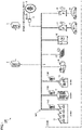
- FIG. 1 shows a schematic configuration of a power management system according to a first embodiment of the present disclosure.
- a power management system 100 includes a CEMS 1, a CEMS server 2, a power reception and transformation facility 3, a power system 4, and a power transmission and distribution business operator server 5.
- CEMS stands for Community Energy Management System or City Energy Management System.
- CEMS 1 includes a factory energy management system (FEMS) 11, a building energy management system (BEMS) 12, a home energy management system (HEMS) 13, a power generator 14, a variable renewable energy (VRE) source 15, an energy storage system (ESS) 16, a plurality of electric vehicle supply equipment (EVSEs) 17, a plurality of battery electric vehicles (BEVs) 8, and a plurality of fuel cell electric vehicles (FCEVs) 9.
- FEMS factory energy management system
- BEMS building energy management system
- HEMS home energy management system
- VRE variable renewable energy
- ESS energy storage system
- EVSEs electric vehicle supply equipment
- BEVs battery electric vehicles
- FCEVs fuel cell electric vehicles
- FEMS 11 is a system that manages supply and demand of electric power used in a factory.
- FEMS 11 includes a factory building (including a lighting fixture, an air-conditioning facility and the like), an industrial facility (such as a production line) and the like that operate using electric power supplied from microgrid MG.
- FEMS 11 may include a power generation facility (such as a power generator or a solar panel) placed in the factory. Electric power generated by the power generation facility may also be supplied to microgrid MG.
- FEMS 11 further includes an FEMS server 110 that can bidirectionally communicate with CEMS server 2.
- BEMS 12 is a system that manages supply and demand of electric power used in a building such as an office or a commercial facility.
- BEMS 12 includes a lighting fixture and an air-conditioning facility placed in the building.
- BEMS 12 may include a power generation facility (such as a solar panel), or may include a cold source system (such as a waste heat recovery system or a heat storage system).
- BEMS 12 further includes a BEMS server 120 that can bidirectionally communicate with CEMS server 2.
- HEMS 13 is a system that manages supply and demand of electric power used at home.
- HEMS 13 includes a household device (such as a lighting fixture, an air-conditioning device and another electric appliance) that operates using electric power supplied from microgrid MG.
- HEMS 13 may also include a solar panel, a household heat pump system, a household cogeneration system, a household power storage battery or the like.
- HEMS 13 further includes an HEMS server 130 that can bidirectionally communicate with CEMS server 2.
- Power generator 14 is a power generation facility that does not depend on weather conditions, and outputs generated electric power to microgrid MG.
- Power generator 14 may include a steam turbine generator, a gas turbine generator, a diesel engine generator, a gas engine generator, a biomass generator, a stationary-type fuel cell or the like.
- Power generator 14 may include a cogeneration system that uses heat generated during power generation.
- VRE source 15 is a power generation facility whose power generation output fluctuates depending on weather conditions, and outputs generated electric power to microgrid MG.
- Fig. 1 shows a photovoltaic power generation facility (solar panel) by way of example, VRE source 15 may include a wind power generation facility instead of or in addition to the photovoltaic power generation facility.
- Energy storage system 16 is a stationary-type power source that stores the electric power generated by VRE source 15 and the like.
- Energy storage system 16 is a secondary battery, and is, for example, a battery (recycled battery) used in a vehicle, such as a lithium ion battery or a nickel-metal hydride battery.
- energy storage system 16 is not limited to the secondary battery, and may be a power to gas device that produces gas fuel (such as hydrogen or methane) using surplus electric power.
- Each of the plurality of EVSEs 17 is electrically connected to microgrid MG so as to allow the exchange of electric power with microgrid MG.
- DC-type EVSEs are used as EVSEs 17.
- FCEV 9 When a charging cable is connected to an outlet 912 (see Fig. 2 ) of each of the plurality of FCEVs 9, electric power can be supplied from FCEV 9 to microgrid MG through EVSE 17. This manner of power supply will also be referred to as "external power feeding".
- EVSE 17 is of DC type, DC power is supplied from FCEV 9 to EVSE 17, and DC/AC conversion is performed by the inverter built into EVSE 17.
- EVSE 17 of DC type is only illustrative, and EVSE 17 may be of AC type.
- DC/AC conversion is performed by a vehicle-mounted inverter (not shown), and the converted AC power is supplied from FCEV 9 to EVSE 17.
- Each FCEV 9 may perform external charging in addition to external power feeding.
- CEMS 1 may include different types of vehicles other than BEVs 8 and FCEVs 9.
- CEMS 1 may include a plug-in hybrid electric vehicle (PHEV) that performs external power feeding in addition to external charging.
- PHEV plug-in hybrid electric vehicle
- Each vehicle may be a vehicle owned by an individual, or may be a vehicle (mobility as a service (MaaS) vehicle) managed by an MaaS business operator.
- MoaS mobility as a service
- CEMS 1 Although one FEMS 11, one BEMS 12, one HEMS 13, one power generator 14, one VRE source 15, and one energy storage system 16 are included in CEMS 1 in the example shown in Fig. 1 , the number of these systems or facilities included in CEMS 1 is arbitrary. CEMS 1 may include a plurality of these systems or facilities. Alternatively, some of these systems or facilities may not be included in CEMS 1. FEMS 11, BEMS 12 and/or HEMS 13 may include a facility such as a power generator, or may include EVSEs 17, BEVs 8 and FCEVs 9.
- Each of FEMS 11 (such as a factory building and an industrial facility), BEMS 12 (such as a lighting fixture and an air-conditioning facility), HEMS 13 (such as a household device), power generator 14, VRE source 15, and energy storage system 16 included in CEMS 1 corresponds to an example of "at least one/a plurality of power adjustment resources" according to the present disclosure.
- each of BEVs 8 and FCEVs 9 also corresponds to an example of "at least one/a plurality of power adjustment resources" according to the present disclosure.
- CEMS server 2 is a computer that manages the power adjustment resources in CEMS 1.
- CEMS server 2 includes a controller (not shown), a storage device 21 (see Fig. 5 ) and a communication device (not shown).
- the controller includes a processor, and executes a prescribed computation process.
- Storage device 21 includes a memory that stores a program executed in the controller, and stores various types of information (such as a map, a relational equation and a parameter) used in the program.
- the communication device includes a communication interface, and communicates with the outside (such as another server).
- CEMS server 2 may be an aggregator server.
- the aggregator refers to an electric power supplier that controls a plurality of power adjustment resources and provides an energy management service.
- CEMS server 2 corresponds to an example of "server” according to the present disclosure.
- the server (110, 120, 130) included in each of FEMS 11, BEMS 12 and HEMS 13 can also serve as “server” according to the present disclosure.
- Power reception and transformation facility 3 is provided at an interconnection point (power receiving point) of microgrid MG, and switches between parallel on (connection) and parallel off (disconnection) of microgrid MG and power system 4.
- Power reception and transformation facility 3 includes a high-voltage-side (primary-side) switchgear, a transformer, a protective relay, a measuring device, and a controller, although all are not shown.
- power reception and transformation facility 3 receives AC power having, for example, a particularly high voltage (voltage exceeding 7000 V) from power system 4, and steps down the received electric power, which is supplied to microgrid MG.
- Power system 4 is a power grid formed by a power plant and a power transmission and distribution facility.
- an electric power company serves as a power generation business operator and a power transmission and distribution business operator.
- the electric power company corresponds to a general power transmission and distribution business operator and also corresponds to a manager of power system 4, and the electric power company performs maintenance and management of power system 4.
- Power transmission and distribution business operator server 5 belongs to the electric power company, and is a computer that manages power supply and demand in power system 4. Power transmission and distribution business operator server 5 can also bidirectionally communicate with CEMS server 2.
- a manager of CEMS 1 has a power contract with the electric power company.
- the electric power company supplies electric power to microgrid MG formed in CEMS 1, and gets paid.
- the electric power received by microgrid MG from power system 4 is determined based on the power contract.
- this electric power will be referred to as "contract power”.
- the contract power may be a value (kWh/h) obtained by dividing an amount of electric power (kWh) during a prescribed target time period by a length (h) of the target time period.
- the target time period is set at intervals of 30 minutes, and every time the target time period elapses, the amount of electric power during the target time period is evaluated.
- CEMS server 2 adjusts power supply and demand in microgrid MG such that the electric power supplied from power system 4 to microgrid MG during the target time period satisfies the contract power.
- the supplied electric power satisfies the contract power means that the supplied electric power during the target time period is neither too much nor too little with respect to the contract power (falls within a range determined as the contract power).
- power adjustment resource identification information (resource ID) is assigned to each power adjustment resource.
- CEMS server 2 Based on the resource ID, CEMS server 2 identifies and manages data about a state (such as consumed power, generated power and an amount of stored power) of each power adjustment resource.
- CEMS server 2 obtains the state of each power adjustment resource by communication with the power adjustment resource (or a detection value from a sensor, or the like), and updates the above-described data based on a result of obtainment.
- CEMS server 2 can remotely control a charging and discharging operation of this selected power adjustment resource.
- each FCEV 9 when the plurality of FCEVs 9 are connected to EVSEs 17, each FCEV 9 performs external power feeding in accordance with an instruction from CEMS server 2. Electric power is supplied from each FCEV 9 to microgrid MG under remote control by CEMS server 2, and thus, power supply and demand in microgrid MG is adjusted.
- each EVSE 17 and CEMS server 2 communicate with each other directly.
- Each FCEV 9 and CEMS server 2 communicate with each other indirectly through EVSE 17.
- CEMS server 2 manages information about each FCEV 9 (vehicle information) and information about each EVSE 17 (EVSE information).
- the vehicle information and the EVSE information are identified based on identification information (ID).
- the EVSE information may include a state of FCEV 9 connected to EVSE 17.
- the EVSE information may also include information indicating a combination of FCEV 9 and EVSE 17 connected to each other (e.g., information indicating a combination of a vehicle ID and an EVSE-ID).
- FCEV 9 includes a receptacle 901, a hydrogen tank 902, a supply valve 903, an air filter 904, a compressor 905, an FC stack 906, a step-up converter 907, a power line 908, a battery 909, a step-down converter 910, an auxiliary load 911, outlet 912, an inverter 913, a motor generator 914, and an electronic control unit (ECU) 915.
- ECU electronice control unit
- Receptacle 901 is supplied with a hydrogen fuel from a hydrogen dispenser (not shown) placed in a hydrogen station.
- Hydrogen tank 902 stores the hydrogen fuel supplied through receptacle 901.
- Supply valve 903 adjusts an amount of supply of hydrogen from hydrogen tank 902 to FC stack 906 in accordance with a control command from ECU 915.
- Supply valve 903 corresponds to an example of "hydrogen supply mechanism" according to the present disclosure.
- Air filter 904 removes dust and the like in the air suctioned from the atmosphere.
- Compressor 905 compresses the air suctioned through air filter 904, and supplies the compressed air to FC stack 906.
- Compressor 905 corresponds to an example of "oxygen supply mechanism" according to the present disclosure.
- FC stack 906 is, for example, a structure formed by stacking a plurality of solid-polymer-type fuel cell units in series. Each unit is formed, for example, by bonding catalyst electrodes to both surfaces of an electrolyte film, and sandwiching the catalyst electrodes and the electrolyte film between electrically conductive separators (not shown). FC stack 906 generates electric power by electrochemical reaction of hydrogen supplied to an anode and oxygen (air) supplied to a cathode.
- Step-up converter 907 steps up the electric power generated by FC stack 906 to a high voltage (e.g., several hundred volts) in accordance with a control command from ECU 915, and outputs the stepped-up electric power to power line 908.
- Power line 908 electrically connects step-up converter 907 to inverter 913.
- Battery 909 is electrically connected to power line 908.
- Battery 909 includes an assembled battery composed of a plurality of cells. Each battery cell is, for example, a secondary battery such as a lithium ion battery or a nickel-metal hydride battery. Battery 909 stores electric power for driving motor generator 914, and supplies the electric power to inverter 913. In addition, battery 909 receives electric power generated by motor generator 914 during braking of FCEV 9 and the like, and is charged with the electric power. In the present embodiment, battery 909 can function as an energy buffer that absorbs fluctuations of the external power feeding power from FCEV 9.
- Step-down converter 910 is electrically connected between power line 908 and auxiliary load 911. Step-down converter 910 steps down the electric power transmitted on power line 908 to a prescribed voltage, and outputs the stepped-down electric power to auxiliary load 911.
- Auxiliary load 911 corresponds to various devices that are driven by consuming the electric power supplied from step-down converter 910.
- Auxiliary load 911 may include lamps (such as a head lamp, a fog lamp, a cornering signal lamp, and a corner lamp), an audio device, a car navigation system, an antilock brake system (ABS), an oil pump, meters, a defogger, a wiper and the like.
- auxiliary load 911 may also function as an energy buffer.
- a connector of the charging cable extending from EVSE 17 is fittable to outlet 912.
- Outlet 912 receives the electric power transmitted on power line 908, and outputs the electric power to EVSE 17.
- the electric power generated by FCEV 9 FC stack 906 can be supplied to microgrid MG (external power feeding).
- Inverter 913 is electrically connected between power line 908 and motor generator 914. Inverter 913 drives motor generator 914 based on a drive signal from ECU 915.
- Motor generator 914 is implemented by, for example, a three-phase AC synchronous motor including a rotor having a permanent magnet embedded therein. Motor generator 914 is driven by inverter 913 to generate rotational driving force. The driving force generated by motor generator 914 is transmitted to a not-shown driving wheel.
- ECU 915 includes a processor, a memory and an I/O port, although all are not shown. ECU 915 controls the devices that form FCEV 9, based on a program stored in the memory and signals from various sensors. ECU 915 may be divided into a plurality of ECUs for each function.
- ECU 915 controls external power feeding performed by FCEV 9, in cooperation with CEMS server 2 and EVSE 17 (a not-shown controller in EVSE 17). ECU 915 controls step-up converter 907 such that output power requested for FC stack 906 is calculated and FC stack 906 outputs the calculated power based on an external power feeding command from CEMS server 2 and EVSE 17. ECU 915 corresponds to "controller" according to the present disclosure.
- an oxide film may be formed on a surface of a platinum catalyst (catalyst layer) in a fuel cell.
- a platinum catalyst catalyst layer
- formation of an oxide film on a surface of a platinum catalyst progresses, which may cause a reduction in effective area of the platinum catalyst.
- the performance of the platinum catalyst decreases, which may in turn cause a reduction in power generation efficiency of the fuel cell.
- the inventors of the present disclosure have focused attention on the fact that the oxide film tends to be formed when a cathode potential is sufficiently high due to small power generated by FC stack 906. Conversely, by lowering the cathode potential to a reduction potential, the oxide film can be removed from the surface of the platinum catalyst and the power generation efficiency of FC stack 906 can be recovered.
- an amount of hydrogen supplied to FC stack 906 and/or an amount of oxygen supplied to FC stack 906 are decreased, as compared with when formation of the oxide film does not progress. By doing so, the cathode potential is lowered and the oxide film is removed from the surface of the platinum catalyst.
- this control will also be referred to as "decrease control".
- Fig. 3 is a diagram for illustrating an example of decrease control.
- the horizontal axis represents the elapsed time.
- the vertical axis represents, from top to bottom, the amount of hydrogen supplied to FC stack 906, the amount of oxygen supplied to FC stack 906, and the electric power (supply power) supplied from FCEV 9 to microgrid MG through EVSE 17.
- Power supply from FCEV 9 to microgrid MG is often performed with constant power P1.
- P1 is basically determined by CEMS server 2 in accordance with power supply and demand in microgrid MG. However, P1 may in some cases be restricted by laws and regulations and the like. P1 is set at a value that can satisfy the restriction and maintain a balance of power supply and demand in microgrid MG.
- the amount of hydrogen supplied to FC stack 906 is HI, and the amount of oxygen supplied to FC stack 906 is O1.
- FCEV 9 decreases the amount of supplied hydrogen from H1 to H2 and decreases the amount of supplied oxygen from O1 to O2 during power supply with constant power PI, in accordance with a command from CEMS server 2.
- the cathode potential is lowered, and thus, the oxide film can be removed from the surface of the platinum catalyst.
- decreasing both the amount of supplied hydrogen and the amount of supplied oxygen is only illustrative, and only one of the amount of supplied hydrogen and the amount of supplied oxygen may be decreased. This is because the electrochemical reaction in FC stack 906 is suppressed and the cathode potential can be lowered even when only one of the amount of supplied hydrogen and the amount of supplied oxygen is decreased.
- P2 is a value determined in accordance with an amount of decrease in the amount of supplied hydrogen and/or the amount of supplied oxygen, and can be, for example, electric power that is approximately a fraction of P1.
- CEMS server 2 cause each FCEV 9 to perform external power feeding to microgrid MG as appropriate, to thereby appropriately remove the oxide film formed on the catalyst electrode of each FCEV 9, while adjusting power supply and demand in microgrid MG.
- CEMS server 2 determines execution timings of the decrease control and instructs corresponding FCEVs 9 to execute the decrease control. Particularly, CEMS server 2 adjusts the execution timings of the decrease control in the plurality of FCEVs 9.
- Fig. 4 is a time chart showing the execution timings of the decrease control in the first embodiment.
- the situation in which three FCEVs 9 are included in CEMS 1 is assumed in Fig. 4 .
- three FCEVs 9 are denoted as vehicles V1 to V3.
- the number of FCEVs 9 included in CEMS 1 is not particularly limited, and is larger in many cases.
- CEMS server 2 controls vehicles V1 to V3 such that each of vehicles V1 to V3 repeats the decrease control intermittently.
- each of vehicles V1 to V3 executes the decrease control regularly in accordance with the power command (decrease command) from CEMS server 2. More specifically, each of vehicles V1 to V3 executes the decrease control for a short time period T1, and then, continues power supply with P1 for a long time period T2, and then, again executes the decrease control for short time period T1.
- P1-P2 a difference between P1 and P2
- the decrease in the supply power caused by the decrease control is made up for by another power adjustment resource in CEMS 1.
- the decrease in the supply power caused by the decrease control can be made up for by performing external power feeding from BEV 8 including a battery having a high state of charge (SOC), or temporarily increasing external power feeding power from BEV 8.
- SOC state of charge
- the power generation facility and the like may be used.
- CEMS server 2 in the present embodiment restricts the number of FCEVs 9 that execute the decrease control simultaneously to or below the permissible number set in accordance with a request to adjust power supply and demand in microgrid MG.
- the permissible number is one and the execution timings of the decrease control in vehicles V1 to V3 are adjusted so as not to overlap with each other.
- Power transmission and distribution business operator server 5 transmits, to CEMS server 2, "first adjustment request" to request adjustment of power supply and demand between microgrid MG and power system 4.
- the first adjustment request is, for example, a signal that requests adjustment of a frequency of power system 4 within a prescribed response time period (e.g., five minutes).
- An interval of the requested frequency adjustment may be equal to or longer than 0.5 seconds and equal to or shorter than 30 seconds.
- the first adjustment request may request the frequency adjustment with only a forward power flow or with only a reverse power flow, or may request the forward power flow and the reverse power flow alternately.
- the first adjustment request may be a load frequency control (LFC) signal, or may be an economic load dispatching control (EDC) signal, or may be a superimposed signal of the LFC signal and the EDC signal.
- LFC load frequency control
- EDC economic load dispatching control
- FEMS server 110 the function of FEMS server 110, of FEMS server 110, BEMS server 120 and HEMS server 130, will be described representatively.
- BEMS server 120 and HEMS server 130 may also have an equivalent (or simpler) function.
- Fig. 5 is a functional block diagram showing components of each of FEMS server 110 and CEMS server 2 for each function.
- FEMS server 110 manages the power adjustment resources in FEMS 11 such that a power load and the generated power in FEMS 11 are optimized.
- FEMS server 110 includes a storage device 111, a power load predicting unit 112, a natural power generation predicting unit 113, a private power generation setting unit 114, and an optimum load calculating unit 115.
- Storage device 111 is, for example, a database that stores measurement data, weather data, production plan data, and optimization information.
- the measurement data is data about a past or present state (such as a temperature, an intensity of solar radiation and a power load) of the factory obtained using a not-shown sensor and the like.
- the weather data may include data about future weather conditions (such as a temperature and an intensity of solar radiation) predicted by the Meteorological Agency and the like.
- the production plan data is data about a product production plan in the factory.
- the production plan data is input by, for example, a manager of the factory.
- the optimization information may include, for example, the contract power, information for calculating the power cost, and information for calculating a CO 2 emission intensity.
- power load predicting unit 112 predicts the power load in the factory for carrying out the production plan in the factory.
- the power load in the factory may also fluctuate depending on the temperature and the intensity of solar radiation.
- Power load predicting unit 112 may correct the power load in the factory, using measurement data about the temperature and the intensity of solar radiation. Transition of the power load in the factory is output to optimum load calculating unit 115.
- natural power generation predicting unit 113 predicts electric power generated by the VRE source (not shown) during the target time period. Using a preliminarily prepared power generation prediction map, natural power generation predicting unit 113 can obtain transition of the electric power generated by the VRE source during the target time period, based on the weather conditions during the target time period. The transition of the electric power generated by the VRE source is output to optimum load calculating unit 115.
- private power generation setting unit 114 sets electric power generated by the power generator (not shown) during the target time period.
- natural power generation predicting unit 113 can set transition of the electric power generated by the power generator during the target time period, based on the measurement data and/or the weather data. The transition of the electric power generated by the power generator is output to optimum load calculating unit 115.
- optimum load calculating unit 115 calculates an optimum power load (optimum load) for the factory such that the power cost and the CO 2 emission intensity in the factory become sufficiently low.
- Optimum load calculating unit 115 transmits an adjustment command, a restriction command and a power generation command in accordance with a result of calculation of the optimum load, to thereby adjust power supply and demand in the factory.
- the adjustment command is a command for adjusting the power load in the factory building, the industrial facility and the like.
- the restriction command is a command for restricting the electric power generated by the VRE source, when an amount of the electric power generated by the VRE source in the factory is too large and exceeds a power storage capacity in the factory, for example.
- the power generation command is a command for controlling the electric power generated by the power generator such that the CO 2 emission intensity during the target time period does not become too high.
- optimum load calculating unit 115 generates "second adjustment request" to request adjustment of power supply and demand between the factory and microgrid MG (another component of microgrid MG) during the target time period, based on a difference between an amount of generated power and an amount of consumed power in the factory during the target time period.
- the generated second adjustment request is transmitted to CEMS server 2.
- "Second adjustment request” corresponds to another example of “request to adjust power supply and demand” according to the present disclosure.
- CEMS server 2 In cooperation with each server such as FEMS server 110, CEMS server 2 responds to the first and second adjustment requests.
- CEMS server 2 includes storage device 21, a vehicle selecting unit 22, an optimum load calculating unit 23, and a decrease control managing unit 24.
- CEMS server 2 may include a power load predicting unit, a natural power generation predicting unit and a private power generation setting unit, similarly to FEMS server 110.
- Storage device 21 is a database that stores the vehicle information of each of the vehicles (BEVs 8 and FCEVs 9), the EVSE information of each of EVSEs 17, the above-described measurement data, and the optimization information.
- Vehicle selecting unit 22 obtains an operation schedule of each vehicle (e.g., an operation plan of the MaaS vehicle), and recognizes, as standby vehicles, vehicles that are currently connected to EVSEs 17 and are not scheduled to travel during the target time period, for example. Then, based on the SOCs of the batteries of BEVs 8 recognized as standby vehicles, vehicle selecting unit 22 calculates an amount of electric power that can be externally charged into these BEVs 8 during the target time period. In addition, based on the amount of the hydrogen fuel stored in hydrogen tanks 902 (see Fig. 2 ) of FCEVs 9 recognized as standby vehicles, vehicle selecting unit 22 calculates an amount of electric power that can be externally supplied from these FCEVs 9 during the target time period.
- an operation schedule of each vehicle e.g., an operation plan of the MaaS vehicle
- vehicle selecting unit 22 calculates an amount of electric power that can be externally charged into these BEVs 8 during the target time period.
- vehicle selecting unit 22 selects, from the standby vehicles, vehicles for responding to the first and second adjustment requests.
- a result of selection by vehicle selecting unit 22 is output to optimum load calculating unit 23.
- Optimum load calculating unit 23 receives the first adjustment request during the target time period from power transmission and distribution business operator server 5, and receives the second adjustment request during the target time period from FEMS server 110 (optimum load calculating unit 115). Optimum load calculating unit 23 calculates an optimum load in CEMS 1 such that the power cost and the CO 2 emission intensity of each facility in CEMS 1 become sufficiently low, while responding to the first and second adjustment requests.
- Fig. 6 is a diagram for illustrating an example of a method for calculating the optimum load by CEMS server 2 (optimum load calculating unit 23).
- the amount of electric power generated by VRE source 15 (amount of natural power generation E1) during the target time period is basically determined depending on the weather conditions during the target time period.
- the amount of electric power generated by power generator 14 (amount of private power generation E2) during the target time period is determined such that the CO 2 emission intensity does not become too high.
- Optimum load calculating unit 23 can control a power generation output of power generator 14 in accordance with a control command provided to power generator 14.
- An amount of external power feeding E3 from FCEVs 9 to microgrid MG during the target time period is determined to fall within a range of the amount of electric power that can be externally supplied from FCEVs 9 selected by vehicle selecting unit 22, based on the amount of the hydrogen fuel in hydrogen tanks 902 of these FCEVs 9.
- optimum load calculating unit 23 can control the amount of external power feeding E3.
- An amount of external charging E4 from microgrid MG to BEVs 8 during the target time period is determined to fall within a range of the amount of electric power that can be externally charged into BEVs 8 selected by vehicle selecting unit 22, based on the SOCs of the batteries of these BEVs 8.
- optimum load calculating unit 23 can control the amount of external charging E4.
- An amount of charging E5 from microgrid MG to energy storage system 16 during the target time period is determined to fall within a range of the amount of electric power that can be charged into energy storage system 16, based on the amount of electric power stored in energy storage system 16.
- optimum load calculating unit 23 can control the amount of charging E5.
- An amount of electric power supplied from power system 4 to microgrid MG (amount of system power E6) during the target time period is adjusted to satisfy the contract power.
- the amount of system power E6 is basically determined based on an amount of consumed power E0 by various power loads in CEMS 1 and the above-described amounts of electric power (E1 to E6).
- Optimum load calculating unit 23 calculates the optimum load in CEMS 1 such that the power cost and the CO 2 emission intensity become sufficiently low and the amount of system power E6 during the target time period does not exceed the contract power.
- optimum load calculating unit 23 transmits an adjustment command, a restriction command and a power generation command similarly to optimum load calculating unit 115 of FEMS server 110, and in addition, transmits an external power feeding command to FCEVs 9 and an external charging command to BEVs 8, to thereby adjust power supply and demand in microgrid MG. More specifically, optimum load calculating unit 23 distributes the amount of electric power (amount of external power feeding or amount of external charging) for satisfying the first and second adjustment requests to the vehicles (FCEVs 9 or BEVs 8) selected by vehicle selecting unit 22. A uniform amount of external power feeding may be distributed to respective FCEVs 9, or a larger amount of external power feeding may be distributed to FCEV 9 having a larger remaining amount of hydrogen fuel. A uniform amount of external charging may be distributed to respective BEVs 8, or a larger amount of external charging may be distributed to BEV 8 having a larger remaining amount of electric power (or having a higher SOC) of the battery.
- decrease control managing unit 24 manages the execution timings of the decrease control in FCEVs 9 selected by vehicle selecting unit 22. At this time, in accordance with the optimum load calculated by optimum load calculating unit 23, decrease control managing unit 24 may set the number (permissible number) of FCEVs 9 that may execute the decrease control simultaneously. When there is a margin for making up for electric power fluctuations in BEVs 8 (such as when the number of BEVs 8 is large), the permissible number may be set at two or more.
- Vehicle selecting unit 22 optimum load calculating unit 23 and decrease control managing unit 24 are implemented by "processor" according to the present disclosure.
- Fig. 7 is a flowchart showing a power supply and demand adjustment method in the first embodiment. The process shown in this flowchart is repeatedly executed at prescribed time intervals, for example.
- the process executed by CEMS server 2 is shown on the left side
- the process executed by FCEV 9 is shown on the right side.
- each step is implemented by software processing by the controller of CEMS server 2 or ECU 915 of FCEV 9
- each step may be implemented by hardware (electric circuit) formed in the controller or ECU 915.
- S each step will be abbreviated as "S”.
- CEMS server 2 obtains, from power transmission and distribution business operator server 5, "first adjustment request” to request adjustment of power supply and demand between microgrid MG and power system 4.
- CEMS server 2 obtains, from each server in CEMS 1, "second adjustment request” to request adjustment of power supply and demand in microgrid MG.
- CEMS server 2 obtains, from FEMS server 110, the second adjustment request to adjust power supply and demand among FEMS 11, BEVs 8 and FCEVs 9.
- CEMS server 2 calculates the optimum load in CEMS 1.
- the calculation method has been described in detail with reference to Figs. 5 and 6 , and thus, description will not be repeated.
- As a result of calculation of the optimum load a plurality of FCEVs 9 that perform external power feeding, and BEVs 8 and energy storage system 16 that perform external charging are selected.
- CEMS server 2 transmits the external power feeding command to FCEVs 9 (in this example, EVSEs 17 connected to these vehicles) selected in S12. In addition, CEMS server 2 transmits the external charging command to BEVs 8 (EVSEs 17 connected to these vehicles) selected in S12.
- FCEVs 9 When FCEVs 9 receive the external power feeding command from CEMS server 2 (YES in S21), FCEVs 9 perform external power feeding with constant power P1 in a normal state (S22). Although P1 may be a predetermined value (fixed value), P1 may be a value (variable value) determined by CEMS server 2 such that the optimum load in CEMS 1 is achieved. When FCEVs 9 do not receive the external power feeding command from CEMS server 2 (NO in S21), FCEVs 9 await without performing external power feeding.
- P1 may be a predetermined value (fixed value)
- P1 may be a value (variable value) determined by CEMS server 2 such that the optimum load in CEMS 1 is achieved.
- CEMS server 2 selects in order FCEVs 9 that execute the decrease control, from the plurality of FCEVs 9 that have received the external power feeding command. More specifically, when transmission of the command (decrease command) to execute the decrease control to certain FCEV 9 (processing in S15 described below) is completed, CEMS server 2 selects a next vehicle. In the example shown in Fig. 4 , vehicle VI, vehicle V2 and vehicle V3 are selected in this order.
- CEMS server 2 determines whether or not a prescribed time period (e.g., several tens of minutes) has elapsed from the previous decrease control.
- a prescribed time period e.g., several tens of minutes
- CEMS server 2 transmits the decrease command to selected FCEVs 9 (EVSEs 17 connected to these vehicles) (S16).
- the decrease command is not transmitted to the same FCEV 9 until the prescribed time period elapses from the previous decrease control (NO in S15).
- FCEVs 9 When FCEVs 9 receive the decrease command from CEMS server 2 (YES in S23), FCEVs 9 execute the decrease control (S24). Specifically, as described with reference to Fig. 3 or 4 , FCEVs 9 temporarily decrease the electric power supplied to microgrid MG from P1 in a normal state to P2.
- respective FCEVs 9 execute the decrease control regularly in accordance with the control by CEMS server 2.
- the execution timings of the decrease control in the plurality of FCEVs 9 are adjusted so as not to overlap with each other. Therefore, even when the electric power supplied from FCEVs 9 to microgrid MG decreases temporarily due to the decrease control, an influence on adjustment of power supply and demand between microgrid MG and power system 4 can be minimized.
- the oxide films formed on the catalyst electrodes of FCEVs 9 can be appropriately removed during external power feeding from FCEVs 9 to microgrid MG.
- the execution timings of the decrease control are not necessarily adjusted to be different from each other among all of FCEVs 9 that have received the external power feeding command.
- the execution timings of the decrease control are not necessarily adjusted to be different from each other among all of FCEVs 9 that have received the external power feeding command.
- not more than the permissible number of FCEVs 9 may execute the decrease control simultaneously.
- two FCEVs 9 may be selected at a time, and selected two FCEVs 9 may execute the decrease control simultaneously.
- Fig. 8 is a flowchart showing a power supply and demand adjustment method in the second embodiment.
- the processing in S31 to S33 is similar to the processing in S11 to S13 in the first embodiment (see Fig. 7 ).
- FCEVs 9 receive the external power feeding command from CEMS server 2 (YES in S41), FCEVs 9 perform external power feeding with P1 in a normal state (S42).
- the resistance of the catalyst electrode increases, as compared with when the oxide film is not formed on the catalyst electrode. Therefore, assuming that the electric power generated by the fuel cell is constant, an amount of voltage drop during power generation becomes larger as the formation of the oxide film progresses. From a different perspective, a degree of formation of the oxide film can be estimated based on the amount of voltage drop during power generation in the fuel cell.
- each FCEV 9 monitors a power generation voltage of FC stack 906 using a not-shown voltage sensor. Then, FCEV 9 determines whether or not the power generation voltage has decreased below a prescribed voltage (e.g., an initial value or a specification value in a state where the oxide film is not formed on the catalyst electrode of FC stack 906) (S43). FCEV 9 may determine whether or not the power generation voltage has decreased, based on an amount of decrease in the power generation voltage within a predetermined time range.
- a prescribed voltage e.g., an initial value or a specification value in a state where the oxide film is not formed on the catalyst electrode of FC stack 906
- FCEV 9 transmits a request (decrease request) for permission of execution of the decrease control to CEMS server 2 through EVSE 17 (S44).
- CEMS server 2 determines the order of execution of the decrease control (S35). For example, CEMS server 2 may determine the order of execution in accordance with a remaining time period in which each FCEV 9 can continue external power feeding. As one example, when the remaining time period is short, the decrease control may be executed preferentially. Alternatively, CEMS server 2 may determine the order of execution in accordance with a predetermined priority based on the vehicle ID, the EVSE-ID or the like.
- CEMS server 2 transmits permissions to execute the decrease control (decrease permissions) to FCEVs 9 (EVSEs 17 connected to these vehicles) in ascending order of execution (S36).
- CEMS server 2 can transmit the decrease permission to FCEV 9 that has transmitted the decrease request (S35).
- FCEV 9 awaits until FCEV 9 receives the decrease permission from CEMS server 2 (NO in S45). When FCEV 9 receives the decrease permission (YES in S45), FCEV 9 executes the decrease control similarly to the first embodiment (S46).
- CEMS server 2 transmits the decrease permission in response to the decrease request from each FCEV 9.
- CEMS server 2 determines the order of execution of the decrease control in accordance with the prescribed procedure, and thus, the execution timings of the decrease control in the plurality of FCEVs 9 are adjusted so as not to overlap with each other. Therefore, even when the electric power supplied from FCEVs 9 to microgrid MG decreases temporarily due to the decrease control, an influence on adjustment of power supply and demand between microgrid MG and power system 4 can be minimized.
- the oxide films formed on the catalyst electrodes can be appropriately removed during external power feeding from FCEVs 9 to microgrid MG.
- CEMS server 2 may simultaneously transmit the decrease permissions to not more than the permissible number of FCEVs 9.
- the decrease control By simply executing the decrease control intermittently or regularly as in the first embodiment, a computation process executed by CEMS server 2 to manage the execution timings of the decrease control can be simplified. As a result, implementation of CEMS server 2 becomes easy. In contrast, in the first embodiment, the decrease control may be executed even when the oxide film is not formed on the catalyst electrode of FC stack 906.
- the power generation voltage of FC stack 906 is monitored, and the decrease request is transmitted from FCEV 9 based on the condition that the power generation voltage has decreased.
- the decrease control is executed only when the formation of the oxide film on the catalyst electrode is estimated, and thus, unnecessary execution of the decrease control can be prevented.
Landscapes
- Engineering & Computer Science (AREA)
- Power Engineering (AREA)
- Sustainable Energy (AREA)
- Life Sciences & Earth Sciences (AREA)
- Sustainable Development (AREA)
- Chemical & Material Sciences (AREA)
- Manufacturing & Machinery (AREA)
- Chemical Kinetics & Catalysis (AREA)
- Electrochemistry (AREA)
- General Chemical & Material Sciences (AREA)
- Transportation (AREA)
- Mechanical Engineering (AREA)
- Fuel Cell (AREA)
- Supply And Distribution Of Alternating Current (AREA)
- Inert Electrodes (AREA)
Applications Claiming Priority (1)
| Application Number | Priority Date | Filing Date | Title |
|---|---|---|---|
| JP2020212342A JP7472777B2 (ja) | 2020-12-22 | 2020-12-22 | 電力システム、サーバおよび電力需給の調整方法 |
Publications (1)
| Publication Number | Publication Date |
|---|---|
| EP4020743A1 true EP4020743A1 (fr) | 2022-06-29 |
Family
ID=78827690
Family Applications (1)
| Application Number | Title | Priority Date | Filing Date |
|---|---|---|---|
| EP21213210.4A Withdrawn EP4020743A1 (fr) | 2020-12-22 | 2021-12-08 | Système de gestion d'alimentation, serveur et alimentation électrique et procédé de réglage de la demande |
Country Status (4)
| Country | Link |
|---|---|
| US (1) | US20220200021A1 (fr) |
| EP (1) | EP4020743A1 (fr) |
| JP (1) | JP7472777B2 (fr) |
| CN (1) | CN114665462A (fr) |
Families Citing this family (3)
| Publication number | Priority date | Publication date | Assignee | Title |
|---|---|---|---|---|
| DE112021000464T5 (de) * | 2020-09-04 | 2022-12-22 | Hyundai Glovis Co., Ltd. | Plattform und verfahren zur optimierung der verwaltung eines wasserstoffversorgungsnetzes |
| KR20240174378A (ko) * | 2023-06-08 | 2024-12-17 | 삼성전자주식회사 | Vtc 및 이의 동작 방법 |
| CN118231709A (zh) * | 2024-05-21 | 2024-06-21 | 北京卡文新能源汽车有限公司 | 恢复燃料电池堆阴极催化剂的方法、燃料电池控制器、介质、燃料电池堆系统和车辆 |
Citations (3)
| Publication number | Priority date | Publication date | Assignee | Title |
|---|---|---|---|---|
| US9225029B2 (en) * | 2011-08-16 | 2015-12-29 | Nissan North America, Inc. | System and method for the recovery of fuel cell catalyst performance |
| JP2019129062A (ja) | 2018-01-24 | 2019-08-01 | 三菱自動車工業株式会社 | 燃料電池の制御装置及び制御方法 |
| US20200317075A1 (en) * | 2017-12-28 | 2020-10-08 | Honda Motor Co., Ltd. | Vehicle management system |
Family Cites Families (5)
| Publication number | Priority date | Publication date | Assignee | Title |
|---|---|---|---|---|
| JP2007006574A (ja) | 2005-06-22 | 2007-01-11 | Hitachi Ltd | 電力供給システム |
| JP5023374B2 (ja) | 2007-02-05 | 2012-09-12 | トヨタ自動車株式会社 | 燃料電池システム |
| JP5617696B2 (ja) | 2011-03-04 | 2014-11-05 | トヨタ自動車株式会社 | 燃料電池システム及び燃料電池の触媒性能回復方法 |
| US20150125772A1 (en) | 2012-03-01 | 2015-05-07 | Toyota Jidosha Kabushiki Kaisha | Fuel cell system |
| JP6943170B2 (ja) | 2017-12-19 | 2021-09-29 | トヨタ自動車株式会社 | 燃料電池システム |
-
2020
- 2020-12-22 JP JP2020212342A patent/JP7472777B2/ja active Active
-
2021
- 2021-11-17 US US17/528,311 patent/US20220200021A1/en not_active Abandoned
- 2021-12-08 EP EP21213210.4A patent/EP4020743A1/fr not_active Withdrawn
- 2021-12-21 CN CN202111573500.0A patent/CN114665462A/zh not_active Withdrawn
Patent Citations (3)
| Publication number | Priority date | Publication date | Assignee | Title |
|---|---|---|---|---|
| US9225029B2 (en) * | 2011-08-16 | 2015-12-29 | Nissan North America, Inc. | System and method for the recovery of fuel cell catalyst performance |
| US20200317075A1 (en) * | 2017-12-28 | 2020-10-08 | Honda Motor Co., Ltd. | Vehicle management system |
| JP2019129062A (ja) | 2018-01-24 | 2019-08-01 | 三菱自動車工業株式会社 | 燃料電池の制御装置及び制御方法 |
Also Published As
| Publication number | Publication date |
|---|---|
| JP7472777B2 (ja) | 2024-04-23 |
| US20220200021A1 (en) | 2022-06-23 |
| CN114665462A (zh) | 2022-06-24 |
| JP2022098760A (ja) | 2022-07-04 |
Similar Documents
| Publication | Publication Date | Title |
|---|---|---|
| US8744641B2 (en) | Electric power supply system | |
| US12040617B2 (en) | Electric power system, server, charge-and-discharge controller, and power demand-and-supply adjustment method | |
| KR101775957B1 (ko) | 태양광 발전 장치 연계형 전원공급시스템 | |
| EP4039535B1 (fr) | Système d'alimentation électrique | |
| EP4020743A1 (fr) | Système de gestion d'alimentation, serveur et alimentation électrique et procédé de réglage de la demande | |
| CN107534293A (zh) | 使用了利用可再生能源的发电设备的电力供给系统 | |
| US11710966B2 (en) | Server and power management method | |
| US12237685B2 (en) | Power management system, server, and power supply and demand adjustment | |
| US12362375B2 (en) | Electric power system | |
| US12280693B2 (en) | Power management system, electric vehicle supply equipment, server, and adjustment method of power supply and demand balance | |
| CN112701685A (zh) | 车辆充电站及其控制方法 | |
| EP4039534B1 (fr) | Système de gestion d'alimentation, serveur et alimentation électrique et procédé de réglage de la demande | |
| CN119821146A (zh) | 一种车辆供电方法、装置、车辆和存储介质 | |
| US11772507B1 (en) | Energy facility leveraging electric vehicle charging to increase usage of renewable energy | |
| US20230234465A1 (en) | Hybrid electric vehicle management device, hybrid electric vehicle management method, and hybrid electric vehicle management system | |
| US12244145B2 (en) | Power management system, power management server, and power management method | |
| US20240131953A1 (en) | Power system | |
| CN118801350A (zh) | 微电网应急供电控制方法、装置及相关设备 | |
| JP2025033962A (ja) | 電力供給システム及び電力供給システムの運転方法 | |
| CN120185183A (zh) | 一种基于v2g的柴储混合应急电源系统及其控制方法 | |
| CN117833298A (zh) | 一种基于独立型微电网的储能系统优化方法 |
Legal Events
| Date | Code | Title | Description |
|---|---|---|---|
| PUAI | Public reference made under article 153(3) epc to a published international application that has entered the european phase |
Free format text: ORIGINAL CODE: 0009012 |
|
| STAA | Information on the status of an ep patent application or granted ep patent |
Free format text: STATUS: REQUEST FOR EXAMINATION WAS MADE |
|
| 17P | Request for examination filed |
Effective date: 20211208 |
|
| AK | Designated contracting states |
Kind code of ref document: A1 Designated state(s): AL AT BE BG CH CY CZ DE DK EE ES FI FR GB GR HR HU IE IS IT LI LT LU LV MC MK MT NL NO PL PT RO RS SE SI SK SM TR |
|
| STAA | Information on the status of an ep patent application or granted ep patent |
Free format text: STATUS: THE APPLICATION HAS BEEN WITHDRAWN |
|
| 18W | Application withdrawn |
Effective date: 20220805 |