EP4020775A1 - Method and device for laser welding conductor wires - Google Patents
Method and device for laser welding conductor wires Download PDFInfo
- Publication number
- EP4020775A1 EP4020775A1 EP20216262.4A EP20216262A EP4020775A1 EP 4020775 A1 EP4020775 A1 EP 4020775A1 EP 20216262 A EP20216262 A EP 20216262A EP 4020775 A1 EP4020775 A1 EP 4020775A1
- Authority
- EP
- European Patent Office
- Prior art keywords
- end surface
- closed path
- conductor wire
- laser beam
- molten pool
- Prior art date
- Legal status (The legal status is an assumption and is not a legal conclusion. Google has not performed a legal analysis and makes no representation as to the accuracy of the status listed.)
- Withdrawn
Links
- 239000004020 conductor Substances 0.000 title claims abstract description 120
- 238000003466 welding Methods 0.000 title claims abstract description 28
- 238000000034 method Methods 0.000 title claims abstract description 20
- 238000004804 winding Methods 0.000 claims abstract description 10
- 239000000463 material Substances 0.000 description 11
- 239000012768 molten material Substances 0.000 description 7
- 230000005484 gravity Effects 0.000 description 4
- 238000003825 pressing Methods 0.000 description 3
- RYGMFSIKBFXOCR-UHFFFAOYSA-N Copper Chemical compound [Cu] RYGMFSIKBFXOCR-UHFFFAOYSA-N 0.000 description 2
- 229910052802 copper Inorganic materials 0.000 description 2
- 239000010949 copper Substances 0.000 description 2
- 238000003780 insertion Methods 0.000 description 2
- 230000037431 insertion Effects 0.000 description 2
- 238000009413 insulation Methods 0.000 description 2
- 239000000155 melt Substances 0.000 description 2
- 238000002844 melting Methods 0.000 description 2
- 230000008018 melting Effects 0.000 description 2
- 230000004323 axial length Effects 0.000 description 1
- 230000008878 coupling Effects 0.000 description 1
- 238000010168 coupling process Methods 0.000 description 1
- 238000005859 coupling reaction Methods 0.000 description 1
- 238000009826 distribution Methods 0.000 description 1
- 230000000694 effects Effects 0.000 description 1
- 239000000835 fiber Substances 0.000 description 1
- 239000011261 inert gas Substances 0.000 description 1
- 238000005304 joining Methods 0.000 description 1
- 230000035515 penetration Effects 0.000 description 1
- WFKWXMTUELFFGS-UHFFFAOYSA-N tungsten Chemical compound [W] WFKWXMTUELFFGS-UHFFFAOYSA-N 0.000 description 1
- 229910052721 tungsten Inorganic materials 0.000 description 1
- 239000010937 tungsten Substances 0.000 description 1
Images


Classifications
-
- B—PERFORMING OPERATIONS; TRANSPORTING
- B23—MACHINE TOOLS; METAL-WORKING NOT OTHERWISE PROVIDED FOR
- B23K—SOLDERING OR UNSOLDERING; WELDING; CLADDING OR PLATING BY SOLDERING OR WELDING; CUTTING BY APPLYING HEAT LOCALLY, e.g. FLAME CUTTING; WORKING BY LASER BEAM
- B23K26/00—Working by laser beam, e.g. welding, cutting or boring
- B23K26/20—Bonding
- B23K26/21—Bonding by welding
-
- B—PERFORMING OPERATIONS; TRANSPORTING
- B23—MACHINE TOOLS; METAL-WORKING NOT OTHERWISE PROVIDED FOR
- B23K—SOLDERING OR UNSOLDERING; WELDING; CLADDING OR PLATING BY SOLDERING OR WELDING; CUTTING BY APPLYING HEAT LOCALLY, e.g. FLAME CUTTING; WORKING BY LASER BEAM
- B23K26/00—Working by laser beam, e.g. welding, cutting or boring
- B23K26/08—Devices involving relative movement between laser beam and workpiece
- B23K26/082—Scanning systems, i.e. devices involving movement of the laser beam relative to the laser head
-
- B—PERFORMING OPERATIONS; TRANSPORTING
- B23—MACHINE TOOLS; METAL-WORKING NOT OTHERWISE PROVIDED FOR
- B23K—SOLDERING OR UNSOLDERING; WELDING; CLADDING OR PLATING BY SOLDERING OR WELDING; CUTTING BY APPLYING HEAT LOCALLY, e.g. FLAME CUTTING; WORKING BY LASER BEAM
- B23K26/00—Working by laser beam, e.g. welding, cutting or boring
- B23K26/20—Bonding
- B23K26/21—Bonding by welding
- B23K26/24—Seam welding
- B23K26/242—Fillet welding, i.e. involving a weld of substantially triangular cross section joining two parts
-
- B—PERFORMING OPERATIONS; TRANSPORTING
- B23—MACHINE TOOLS; METAL-WORKING NOT OTHERWISE PROVIDED FOR
- B23K—SOLDERING OR UNSOLDERING; WELDING; CLADDING OR PLATING BY SOLDERING OR WELDING; CUTTING BY APPLYING HEAT LOCALLY, e.g. FLAME CUTTING; WORKING BY LASER BEAM
- B23K26/00—Working by laser beam, e.g. welding, cutting or boring
- B23K26/20—Bonding
- B23K26/21—Bonding by welding
- B23K26/24—Seam welding
- B23K26/28—Seam welding of curved planar seams
-
- B—PERFORMING OPERATIONS; TRANSPORTING
- B23—MACHINE TOOLS; METAL-WORKING NOT OTHERWISE PROVIDED FOR
- B23K—SOLDERING OR UNSOLDERING; WELDING; CLADDING OR PLATING BY SOLDERING OR WELDING; CUTTING BY APPLYING HEAT LOCALLY, e.g. FLAME CUTTING; WORKING BY LASER BEAM
- B23K26/00—Working by laser beam, e.g. welding, cutting or boring
- B23K26/20—Bonding
- B23K26/32—Bonding taking account of the properties of the material involved
-
- H—ELECTRICITY
- H02—GENERATION; CONVERSION OR DISTRIBUTION OF ELECTRIC POWER
- H02K—DYNAMO-ELECTRIC MACHINES
- H02K15/00—Processes or apparatus specially adapted for manufacturing, assembling, maintaining or repairing of dynamo-electric machines
- H02K15/06—Embedding prefabricated windings in the machines
- H02K15/062—Windings in slots; Salient pole windings
-
- H—ELECTRICITY
- H02—GENERATION; CONVERSION OR DISTRIBUTION OF ELECTRIC POWER
- H02K—DYNAMO-ELECTRIC MACHINES
- H02K15/00—Processes or apparatus specially adapted for manufacturing, assembling, maintaining or repairing of dynamo-electric machines
- H02K15/30—Manufacture of winding connections
- H02K15/33—Connecting winding sections; Forming leads; Connecting leads to terminals
- H02K15/35—Form-wound windings
-
- B—PERFORMING OPERATIONS; TRANSPORTING
- B23—MACHINE TOOLS; METAL-WORKING NOT OTHERWISE PROVIDED FOR
- B23K—SOLDERING OR UNSOLDERING; WELDING; CLADDING OR PLATING BY SOLDERING OR WELDING; CUTTING BY APPLYING HEAT LOCALLY, e.g. FLAME CUTTING; WORKING BY LASER BEAM
- B23K2101/00—Articles made by soldering, welding or cutting
- B23K2101/32—Wires
-
- B—PERFORMING OPERATIONS; TRANSPORTING
- B23—MACHINE TOOLS; METAL-WORKING NOT OTHERWISE PROVIDED FOR
- B23K—SOLDERING OR UNSOLDERING; WELDING; CLADDING OR PLATING BY SOLDERING OR WELDING; CUTTING BY APPLYING HEAT LOCALLY, e.g. FLAME CUTTING; WORKING BY LASER BEAM
- B23K2101/00—Articles made by soldering, welding or cutting
- B23K2101/36—Electric or electronic devices
- B23K2101/38—Conductors
-
- B—PERFORMING OPERATIONS; TRANSPORTING
- B23—MACHINE TOOLS; METAL-WORKING NOT OTHERWISE PROVIDED FOR
- B23K—SOLDERING OR UNSOLDERING; WELDING; CLADDING OR PLATING BY SOLDERING OR WELDING; CUTTING BY APPLYING HEAT LOCALLY, e.g. FLAME CUTTING; WORKING BY LASER BEAM
- B23K2103/00—Materials to be soldered, welded or cut
- B23K2103/08—Non-ferrous metals or alloys
- B23K2103/12—Copper or alloys thereof
Definitions
- the present invention relates to a method for laser welding conductor wires, in particular conductor wires arranged in slots of a core of a dynamo electric machine, such as a stator core, to form a winding and a device for laser welding conductor wires.
- a stator of a motor includes a stator core and a plurality of segment coils that are arranged in slots of the stator core.
- the segment coils may be formed by a conductor wire, in particular a flat wire made of copper and coated with an insulating film.
- the conductor wire may be provided by pin conductors, such as I-pin or hairpin conductors, which may be inserted into the slots of the stator core from one axial side of the stator core.
- Hairpin conductors are typically provided with two legs and a bridge portion joining the two legs. One leg is inserted into one slot. The bridge portions extend axially outward of the stator on one axial side of the stator core whereas the legs extend out of the slots on the opposite axial side of the stator core. I-pin conductors only comprise one leg.
- Ends of the pin conductors are joined to one another by welding to form a stator winding.
- welding for example, plasma welding, resistance welding or tungsten inert gas welding may be used here.
- Laser beam welding is often used on account of high possibilities for precision of the weld, automation and low cycle times.
- Coupling the laser beam into the material produces a melt, which leads to the components being connected to one another.
- an oblique positioning of the laser beam or the components by at most 0-15° to one another can be made, depending on the manufacturer of the laser source.
- EP3292940 A1 discloses to apply a laser beam to a first end surface of a first flat wire and a second end surface of a second flat wire to weld together the first side surface and the second side surface.
- the laser beam is applied inside the first end surface while gradually increasing the diameter of a loop-shaped trajectory of the laser beam to allow the molten pool to reach a first side surface and a second side surface butted together. Thereby, a clearance between the first and the second flat wire may be filled.
- US2020067388A1 discloses that the conductor ends are inclined in relation to a perpendicular direction. This leads to the bridge formed by laser welding running between the first conductor and the second conductor obliquely to the axial direction. Due to gravity, the melt may bridge a gap between the conductor ends.
- slits may be formed in the ends of the conductors, such that melting can be achieved with a reduced heat input.
- US20200083787 A1 teaches to scan the laser beam in a plurality of continuous loop shapes from one or both welding end portions.
- Ends of conductor wires may be sharpened for easier insertion into the slots of the core of a dynamo electric machine.
- the ends of the conductor wires then do not comprise a flat surface, such that the laser beam does not have a homogenous power distribution over the end surface due to different distances and to the fact that the clearance between two sharpened ends varies along the axial length of the conductor wires.
- the ends may be cut off before laser welding to provide flat ends. However, copper material is wasted in this case.
- the method according to the invention is used for laser welding conductor wires.
- a first end of a first conductor wire and a second end of a second conductor wire are arranged adjacent to each other.
- the conductor wires are arranged in slots of a core of a dynamo electric machine, such as a stator core or an armature or rotor core, to form a winding when they are connected.
- a core of a dynamo electric machine such as a stator core or an armature or rotor core
- axial, circumferential and radial refer to the geometry of the core.
- a laser beam is applied to a first end surface of the first conductor wire and a second end surface of the second conductor wire to weld together the first end of the first conductor wire and the second end of the second conductor wire.
- a first side surface of the first end of the first conductor wire and a second side surface of the second end of the second conductor wire face each other and preferably touch each other.
- the adjacent conductor wires are neighbours in a radial direction, such that the first side surface is a first radial surface and the second side surface is a second radial surface, which face each other.
- the first end surface and the second end surface preferably point upwards.
- the first end surface and the second end surface preferably each comprise a substantially vertical face normal. That means the mean value of face normal is within an angle of +/- 10° towards the gravity vector.
- a core of a dynamo electric machine hosting the conductor wires is arranged such the core axis is directed vertically and the core axis is aligned with the gravity vector.
- the first end surface and the second end surface may point axially.
- the first end surface and the second end surface may have a substantially axial face normal.
- the first side surface and the second side surface may face radially.
- the ends of the conductor wires may point in radial or circumferential direction.
- the ends of the conductor wires may be bent towards the outside or inside of the core.
- the first end surface and/or the second end surface against which the laser beam is directed may be parts of the side faces of the conductor wires facing radially.
- the first side surface and the second side surface may then face circumferentially.
- the conductor wires may be bent towards the outside or inside of the core and the first end surface and/or the second end surfaces against which the laser beam is directed may point also to the outside or inside of the core.
- the core of a dynamo electric machine hosting the conductor wires may be arranged such the core axis is arranged at an angle, for example perpendicularly, to the gravity vector.
- the first end surface and/or the second end surface against which the laser beam is directed may be parts of the side faces of the conductor wires.
- the first end surface and/or the second end surface of two radially adjacent conductor wires to be connected may face circumferentially and at the same time point upwards.
- At least one laser tool for generating the laser beam and/or for guiding the laser beam is arranged above the first end surface and the second end surface.
- the laser tool may also be arranged next to end surfaces facing in a radial direction such that an essentially horizontally arranged welding beam may be applied to end surfaces pointing for example radially.
- a first step (i) the laser beam is applied within the first end surface in a first substantially closed path to form a first molten pool.
- substantially closed means that the path encompasses at least an angle of 270° and preferably is completely closed.
- a second step (ii) the laser beam is applied within the second end surface in a second substantially closed path to form a second molten pool.
- the second step is performed subsequently to the first step and by the same laser tool.
- the first step (i) and the second step (ii) may be performed simultaneously.
- the horizontal surface of the molten pool may remain stationary within the respective conductor wire.
- the diameter of the substantially closed path and/or second substantially closed path may be smaller than half of the diameter of the conductor wires or may be smaller than half of the shorter length of a rectangular contour of the conductor wire.
- the laser beam is applied in a third step (iii) to the first end surface and to the second end surface in a path from the first molten pool to the second end surface.
- the third step (iii) is performed subsequently to the first step (i) and before the second step (ii).
- the third step (iii) may be performed by the same laser tool as step (i) and step (ii).
- the laser beam is applied in a straight path.
- the laser beam may create a molten line, along which material may flow from the first molten pool into the region between the two conductor wires.
- material may be transferred from the first pool towards the second end, especially into a gap between the two conductor wires.
- the laser beam may be applied to the first end surface and to the second end surface in a third substantially closed path connecting the first and second molten pool.
- the fourth step (iv) is performed subsequently to the first step (i) and the third step (iii) and more preferably to the second step.
- the fourth step (iv) may be performed by the same laser tool as step (i) and step (ii), and preferably as step (iii).
- the first step (i) is performed and subsequently the laser beam is applied on a path corresponding to the first part of the third substantially closed path which starts at the first molten pool and ends on the second end surface.
- the second step (ii) is performed and subsequently the third substantially closed path is completed.
- the first and the second molten pool may be joined to a common molten pool, which connects the first end of the first conductor wire and the second end of the second conductor wire as soon as the common molten pool has been cooled and solidified.
- the conductor wires are flat wire conductors having a rectangular cross-section.
- the axial end faces may have a rectangular shape and are for example flat.
- the first and/or the second conductor wire may be the leg of pin conductor, such as a hairpin or an I-pin.
- the radial surface and/or the circumferential surface of the conductor wires may be provided with an insulation layer.
- the insulation layer may be removed at least from parts of the first side surface and the second side surface before starting with the first step (i) and/or the second step (ii).
- the laser beam may be guided to the second end surface, preferably in a straight path.
- the laser is in operation during this movement, such that step (iii) is performed.
- the first substantially closed path and/or second substantially closed path may be circular.
- the first and/or the second molten pool may have circular surfaces.
- the third substantially closed path may be elliptical.
- the ellipse may be arranged between and tangentially to the first molten pool and to the second molten pool.
- the minor axis of the ellipse is smaller than the diameter of the conductor wires or smaller than the shorter lengths of a rectangular contour of the conductor wires. Hence the path stays well inside of a contour surrounding the first end surface and the second end surface.
- Molten material may reach a gap between the conductor wires but does not flow out of a contour connecting the two conductor wires.
- the first step (i), the second step (ii) and/or the fourth step (iv), wherein the laser beam is applied in substantially closed paths, may be repeated 1 or 2 times in order to supply sufficient energy to the first and second end for melting.
- the second steps (ii) are performed subsequently to the first steps (i) and the fourth steps (iv) are performed subsequently to the second steps.
- a first molten pool having an appropriate amount of molten material is formed at the first end of the first conductor wire, subsequently a second molten pool having an appropriate amount of molten material is formed at the second end of the second conductor wire and the molten pools are combined to a common amount of molten material forming a connection between the first and the second end as soon as the material has solidified.
- the laser beam may be applied in a fourth substantially closed path to the first end surface and to the second end surface surrounding the first closed path, the second closed path and third closed path.
- the fourth substantially closed path may also be elliptical.
- the ellipse may be arranged outside and tangentially to the first molten pool and to the second molten pool.
- the minor axis of the ellipse of the fourth path is also smaller than the diameter of the conductor wires or smaller than the shorter lengths of a rectangular contour of the conductor wires.
- the fourth path stays well inside of a contour surrounding the first end surface and the second end surface.
- the amount of melted material may be enlarged.
- sufficient energy may be supplied to the first and the second end.
- the minor and the major axes of the third elliptical path may be continuously increased to reach the fourth path.
- the laser beam may be guided along a straight line, preferably extending the path of the third step.
- the cross-sectional area of the first end of the first conductor wire and/or the cross-sectional area of the second end of the second conductor wire may get smaller toward the end of the respective conductor wire.
- the ends may be tapered, for example when the ends are sharpened for facilitating insertion into the slots of the core of the dynamo electric machine.
- the gap When generating the first pool and applying the laser beam in a straight path from the first molten pool to the second end the gap may be started to be filled with molten material, wherein material is provided by the first molten pool.
- the gap When generating the molten pool within the first end and the molten pool within the second end and when connecting the first and the second pool , the gap may be filled with molten material, wherein material is provided by both of the conductor wire ends. When the gap is filled, the ends are connected. As the paths remain within the contour of the first and the second ends, the melted material also remains within this contour and mainly fills a gap and connects the ends.
- the melted material will not flow out of the contour.
- connection area has a surface which during the connection process points upwards, preferably in an axial direction.
- the first and/or second end surface may not be a flat surface. Because in the first and the second step molten pools are generated within the first and the second end surface, the surfaces are flattened during the first step and the second step.
- the laser is currently in operation and a laser beam is applied to the conductor wires during and between the steps.
- a continuous operating prevents impacts and/or micro bubbles which could arise, when the laser is switched on.
- a device for laser welding conductor wires according to the invention can be used for welding conductor wires arranged in slots of a core of a dynamo electric machine, such as a stator core or an armature or wound rotor core, to form a winding, for example a stator winding.
- the device is a device for performing a method as described above.
- the device comprises at least one laser tool for generating a moveable laser beam and/or applying a moveable laser beam to a first end surface of a first conductor wire and a second end surface of a second conductor wire for welding together the first end of the first conductor wire and the second end of the second conductor wire.
- the laser tool may comprise a laser generator and/or a moveable mirror.
- the conductor wires, and in particular the core may be arranged, for example in a holder, such that the laser tool preferably is positionable above the first end surface and the second end surface, which point upwards, in particular axially.
- the first and the second ends are positioned adjacently to each other, such that the first side surface and the second side surface face each other, preferably in a radial direction.
- the side surfaces may abut or may at least be arranged close to each other.
- the device may comprise a pressing device for holding the first and the second end together in a radial and/or circumferential direction.
- the device comprises a control unit having an output which is in operative connection with the laser tool, e.g. a line connected or connectable to the laser tool.
- the control unit is configured for controlling the laser tool such that the laser beam is applied in a first substantially closed path within the first end surface to form a first molten pool.
- control unit is configured for controlling the laser tool such that the laser beam is moved to the second end surface, preferably in a straight path, after having formed the first pool.
- the control unit is configured for controlling the laser tool such that the laser beam is applied in a second substantially closed path within the second end surface to form a second molten pool.
- the control unit is configured for controlling the laser tool such that the laser beam is applied in a third substantially closed path to the first end surface and to the second end surface connecting the first molten pool and the second molten pool.
- control unit is configured for controlling the laser tool such that the laser beam is applied in a fourth substantially closed path to the first end surface and to the second end surface surrounding the first closed path, the second closed path and third closed path.
- the applied laser energy is not necessarily kept constant.
- the first and the second step, when the first and the second molten pool are formed, may need more energy than applying the laser beam on the third and fourth substantially closed paths, when the molten pools are connected.
- the laser beam is applied with a power of 3-5 kW for 0.15 - 0.30 seconds, depending on the size of the conductor wires.
- Figure 1 shows a part of a stator 1 in a perspective view.
- Conductor wires 5, 7 are arranged in slots 2 of a stator core 3. Pairs of conductor wires 5, 7 have to be connected to form a stator winding.
- the stator core 3 is arranged such that the direction of the stator axis A is aligned with the gravitational vector.
- a first end 4 of a first conductor wire 5 and a second end 6 of a second conductor wire 7 are arranged adjacent to each other in radial direction.
- a first end surface 8 of the first conductor wire 5 and a second end surface 10 of the second conductor wire 7 point upwards.
- a laser beam 31 (see Figure 3 ) is applied to the first end surface 8 and the second end surface 10 to weld together the first end 4 of the first conductor wire 5 and the second end 6 of the second conductor wire 7.
- FIG. 2 is a schematic drawing of welding paths 20, 21, 22, 23, 24.
- a laser beam 31 (see figure 3 ) is applied within the first end surface 8 in a first circular path 21.
- the circular path 21 is repeated for several times.
- the laser beam 31 (see figure 3 ) is moved to the second end surface 10 via a straight path 20, while the laser beam 31 is still applied.
- a second step (ii) the laser beam 31 (see figure 3 ) is applied in a second circular path 22 within the second end surface 10 to form a second molten pool 26 (see figure 3 ).
- the laser beam 31 (see figure 3 ) is applied in a third elliptical path 23 to the first end surface 8 and to the second end surface 10 connecting the first and second molten pool and welding together a first radial surface 9 of the first conductor wire 5 and a second radial surface 11 of the second conductor wire 7.
- the third elliptical path may be repeated for at least 1-2 times to increase the depths of penetration of the molten pool in the area of the first radial surface 9 and the second radial surface 11.
- the laser beam 31 (see figure 3 ) is then guided to a fourth elliptical path 24 along a straight path 28.
- the laser beam 31 (see figure 3 ) is applied to the fourth elliptical path 24 to complete the welding.
- the fourth elliptical path may be repeated for several times, for example for 4-5 times.
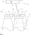
- Figure 3 shows a schematic drawing of a device 35 according to the invention.
- the device 35 comprises a laser tool 30 for generating and applying a moveable laser beam 31 to the first end surface 8 of the first end 4 of the first conductor wire 5 and the second end surface 10 of the second end 8 of the second conductor wire 7.
- the device 35 further comprises a control unit 32 having an output line 33 connected to the laser tool 30.
- the control unit 32 is configured for controlling the laser tool 30 which is arranged above the first end surface 8 and to the second end surface 10 such that the laser beam 31 is applied to the first end surface 8 and to the second end surface 10 in paths as shown in Figure 2 .
- the first end 4 of the first conductor wire 5 and the second end 6 of the second conductor wire 7 are tapered.
- the cross-sectional area 27 gets smaller is axial direction A toward the axial end.
- the laser beam 31 is not passed through the gap 29, thus avoiding reaching areas having a greater distance to the laser tool 30 and where there is no well-defined power input.
- This method allows to weld also conductor wires 5, 7 that are not perfectly in contact with each other. At least one well defined molten pool 25may be generated and from there molten material may be transported towards the other conductor wire.
- a process of this type is more controlled because it may be decided how much of melted material is generated in the molten pools 25, 26 before establishing a connection between the molten pools 25, 26.
- a fiber laser may be used providing a wavelength of 1000 nm.
- the laser beam may be moved with a velocity of 150-350 mm/s.
Landscapes
- Engineering & Computer Science (AREA)
- Physics & Mathematics (AREA)
- Optics & Photonics (AREA)
- Plasma & Fusion (AREA)
- Mechanical Engineering (AREA)
- Manufacturing & Machinery (AREA)
- Power Engineering (AREA)
- Manufacture Of Motors, Generators (AREA)
Priority Applications (10)
| Application Number | Priority Date | Filing Date | Title |
|---|---|---|---|
| EP20216262.4A EP4020775A1 (en) | 2020-12-22 | 2020-12-22 | Method and device for laser welding conductor wires |
| CN202180077981.8A CN116568450A (zh) | 2020-12-22 | 2021-12-22 | 用于激光焊接导电线的方法和装置 |
| US18/251,435 US20240017354A1 (en) | 2020-12-22 | 2021-12-22 | Method and device for laser welding conductor wires |
| RS20250542A RS66860B1 (sr) | 2020-12-22 | 2021-12-22 | Postupak i uređaj za lasersko zavarivanje provodnih žica |
| EP21844662.3A EP4268358B1 (en) | 2020-12-22 | 2021-12-22 | Method and device for laser welding conductor wires |
| ES21844662T ES3033946T3 (en) | 2020-12-22 | 2021-12-22 | Method and device for laser welding conductor wires |
| PL21844662.3T PL4268358T3 (pl) | 2020-12-22 | 2021-12-22 | Sposób i urządzenie do spawania laserowego drutów nawojowych |
| KR1020237020959A KR20230121070A (ko) | 2020-12-22 | 2021-12-22 | 도체 배선을 레이저 용접하기 위한 방법 및 디바이스 |
| PCT/EP2021/087182 WO2022136488A1 (en) | 2020-12-22 | 2021-12-22 | Method and device for laser welding conductor wires |
| SI202130318T SI4268358T1 (sl) | 2020-12-22 | 2021-12-22 | Metoda in naprava za prevodne žice za lasersko varjenje |
Applications Claiming Priority (1)
| Application Number | Priority Date | Filing Date | Title |
|---|---|---|---|
| EP20216262.4A EP4020775A1 (en) | 2020-12-22 | 2020-12-22 | Method and device for laser welding conductor wires |
Publications (1)
| Publication Number | Publication Date |
|---|---|
| EP4020775A1 true EP4020775A1 (en) | 2022-06-29 |
Family
ID=73856685
Family Applications (2)
| Application Number | Title | Priority Date | Filing Date |
|---|---|---|---|
| EP20216262.4A Withdrawn EP4020775A1 (en) | 2020-12-22 | 2020-12-22 | Method and device for laser welding conductor wires |
| EP21844662.3A Active EP4268358B1 (en) | 2020-12-22 | 2021-12-22 | Method and device for laser welding conductor wires |
Family Applications After (1)
| Application Number | Title | Priority Date | Filing Date |
|---|---|---|---|
| EP21844662.3A Active EP4268358B1 (en) | 2020-12-22 | 2021-12-22 | Method and device for laser welding conductor wires |
Country Status (9)
| Country | Link |
|---|---|
| US (1) | US20240017354A1 (sr) |
| EP (2) | EP4020775A1 (sr) |
| KR (1) | KR20230121070A (sr) |
| CN (1) | CN116568450A (sr) |
| ES (1) | ES3033946T3 (sr) |
| PL (1) | PL4268358T3 (sr) |
| RS (1) | RS66860B1 (sr) |
| SI (1) | SI4268358T1 (sr) |
| WO (1) | WO2022136488A1 (sr) |
Cited By (3)
| Publication number | Priority date | Publication date | Assignee | Title |
|---|---|---|---|---|
| CN116833563A (zh) * | 2023-07-21 | 2023-10-03 | 联合汽车电子有限公司 | 一种扁线电机定子焊接工艺 |
| WO2025052767A1 (ja) * | 2023-09-07 | 2025-03-13 | 日立Astemo株式会社 | 電線のレーザー溶接方法 |
| EP4563277A1 (en) * | 2023-12-01 | 2025-06-04 | Kataoka Corporation | Welding method and laser apparatus |
Families Citing this family (4)
| Publication number | Priority date | Publication date | Assignee | Title |
|---|---|---|---|---|
| IT202200024435A1 (it) | 2022-11-28 | 2024-05-28 | Atop Spa | Apparato per la formazione di avvolgimenti induttivi di macchine elettriche. |
| CN118650286B (zh) * | 2024-08-08 | 2025-08-01 | 苏州卡门哈斯激光技术有限责任公司 | 一种扁铜线电机定子绕组激光跳焊方法 |
| CN118951325B (zh) * | 2024-09-10 | 2025-10-17 | 厦门钨业股份有限公司 | 扁线焊接方法、定子绕组及电机 |
| JP7847190B1 (ja) * | 2024-10-23 | 2026-04-16 | 株式会社アマダ | レーザ溶接機及びレーザ溶接方法 |
Citations (5)
| Publication number | Priority date | Publication date | Assignee | Title |
|---|---|---|---|---|
| US20170257002A1 (en) | 2016-03-04 | 2017-09-07 | Denso Corporation | Rotating Electric Machine and Method Of Manufacturing Same |
| JP2018030155A (ja) * | 2016-08-25 | 2018-03-01 | トヨタ自動車株式会社 | 平角線のレーザ溶接方法 |
| EP3292940A1 (en) | 2016-08-02 | 2018-03-14 | Toyota Jidosha Kabushiki Kaisha | Laser welding method for flat wires |
| US20200067388A1 (en) | 2016-11-15 | 2020-02-27 | Robert Bosch Gmbh | Laser welding method for stator |
| US20200083787A1 (en) | 2018-09-12 | 2020-03-12 | Toyota Jidosha Kabushiki Kaisha | Laser welding method for coil wires |
Family Cites Families (3)
| Publication number | Priority date | Publication date | Assignee | Title |
|---|---|---|---|---|
| WO2010021094A1 (ja) * | 2008-08-19 | 2010-02-25 | パナソニック株式会社 | 複合溶接方法および複合溶接装置 |
| EP2969362A1 (en) * | 2013-03-13 | 2016-01-20 | Rolls-Royce Corporation | Variable working distance for deposition |
| WO2018010132A1 (en) * | 2016-07-14 | 2018-01-18 | GM Global Technology Operations LLC | Multi-beam laser spot welding of coated steels |
-
2020
- 2020-12-22 EP EP20216262.4A patent/EP4020775A1/en not_active Withdrawn
-
2021
- 2021-12-22 KR KR1020237020959A patent/KR20230121070A/ko active Pending
- 2021-12-22 EP EP21844662.3A patent/EP4268358B1/en active Active
- 2021-12-22 WO PCT/EP2021/087182 patent/WO2022136488A1/en not_active Ceased
- 2021-12-22 ES ES21844662T patent/ES3033946T3/es active Active
- 2021-12-22 US US18/251,435 patent/US20240017354A1/en active Pending
- 2021-12-22 PL PL21844662.3T patent/PL4268358T3/pl unknown
- 2021-12-22 CN CN202180077981.8A patent/CN116568450A/zh active Pending
- 2021-12-22 SI SI202130318T patent/SI4268358T1/sl unknown
- 2021-12-22 RS RS20250542A patent/RS66860B1/sr unknown
Patent Citations (5)
| Publication number | Priority date | Publication date | Assignee | Title |
|---|---|---|---|---|
| US20170257002A1 (en) | 2016-03-04 | 2017-09-07 | Denso Corporation | Rotating Electric Machine and Method Of Manufacturing Same |
| EP3292940A1 (en) | 2016-08-02 | 2018-03-14 | Toyota Jidosha Kabushiki Kaisha | Laser welding method for flat wires |
| JP2018030155A (ja) * | 2016-08-25 | 2018-03-01 | トヨタ自動車株式会社 | 平角線のレーザ溶接方法 |
| US20200067388A1 (en) | 2016-11-15 | 2020-02-27 | Robert Bosch Gmbh | Laser welding method for stator |
| US20200083787A1 (en) | 2018-09-12 | 2020-03-12 | Toyota Jidosha Kabushiki Kaisha | Laser welding method for coil wires |
Cited By (3)
| Publication number | Priority date | Publication date | Assignee | Title |
|---|---|---|---|---|
| CN116833563A (zh) * | 2023-07-21 | 2023-10-03 | 联合汽车电子有限公司 | 一种扁线电机定子焊接工艺 |
| WO2025052767A1 (ja) * | 2023-09-07 | 2025-03-13 | 日立Astemo株式会社 | 電線のレーザー溶接方法 |
| EP4563277A1 (en) * | 2023-12-01 | 2025-06-04 | Kataoka Corporation | Welding method and laser apparatus |
Also Published As
| Publication number | Publication date |
|---|---|
| EP4268358B1 (en) | 2025-05-14 |
| CN116568450A (zh) | 2023-08-08 |
| KR20230121070A (ko) | 2023-08-17 |
| SI4268358T1 (sl) | 2025-08-29 |
| RS66860B1 (sr) | 2025-06-30 |
| EP4268358A1 (en) | 2023-11-01 |
| US20240017354A1 (en) | 2024-01-18 |
| WO2022136488A1 (en) | 2022-06-30 |
| PL4268358T3 (pl) | 2025-06-30 |
| ES3033946T3 (en) | 2025-08-11 |
Similar Documents
| Publication | Publication Date | Title |
|---|---|---|
| EP4268358B1 (en) | Method and device for laser welding conductor wires | |
| JP5958109B2 (ja) | 回転電機の導体接合方法 | |
| JP7054265B2 (ja) | レーザ溶接方法及びレーザ溶接システム | |
| EP3542452B1 (en) | Method and apparatus for manufacturing a stator of a dynamo-electric machine | |
| US10224789B2 (en) | Apparatus for aligning conductors of coil members in cores of electric dynamo machines | |
| JP7280377B2 (ja) | ヘアピン溶接法およびヘアピン溶接装置 | |
| CN110893517B (zh) | 线圈线的激光焊接方法 | |
| US11349378B2 (en) | Coil segment cutting method and coil segment cutting apparatus | |
| KR100389112B1 (ko) | 회전전기의 고정자 및 그의 제조방법 | |
| JP6593280B2 (ja) | 平角線のレーザ溶接方法 | |
| JP2016208829A (ja) | 電気機械用の剛体棒を伴う固定子巻線の2つの隣接する金属要素を溶接するためのレーザー溶接方法 | |
| JP7103978B2 (ja) | レーザ溶接方法、レーザ溶接装置及び回転電機の製造方法 | |
| CN115427186B (zh) | 激光焊接方法和使用了该激光焊接方法的旋转电机的制造方法 | |
| JPWO2020170413A1 (ja) | 銅を含む部材の溶接方法、および回転電機の製造方法 | |
| JP7432626B2 (ja) | 導線の絶縁被膜の剥離方法 | |
| US11404946B2 (en) | Method for manufacturing a stator | |
| JPH0556609A (ja) | 回転機口出線の自動接続装置 | |
| JP6744060B1 (ja) | 回転電機の固定子及び回転電機 | |
| CN114731100A (zh) | 定子的制造方法 | |
| CN118650286B (zh) | 一种扁铜线电机定子绕组激光跳焊方法 | |
| JP7854915B2 (ja) | 接続部材と絶縁被覆付き電線の導体との接合方法 | |
| EP4336715A1 (en) | Electric motor stator manufacturing device and method for manufacturing electric motor stator | |
| CN113878231A (zh) | 一种电机线圈扁铜线的激光焊接方法 |
Legal Events
| Date | Code | Title | Description |
|---|---|---|---|
| PUAI | Public reference made under article 153(3) epc to a published international application that has entered the european phase |
Free format text: ORIGINAL CODE: 0009012 |
|
| STAA | Information on the status of an ep patent application or granted ep patent |
Free format text: STATUS: THE APPLICATION HAS BEEN PUBLISHED |
|
| AK | Designated contracting states |
Kind code of ref document: A1 Designated state(s): AL AT BE BG CH CY CZ DE DK EE ES FI FR GB GR HR HU IE IS IT LI LT LU LV MC MK MT NL NO PL PT RO RS SE SI SK SM TR |
|
| STAA | Information on the status of an ep patent application or granted ep patent |
Free format text: STATUS: THE APPLICATION IS DEEMED TO BE WITHDRAWN |
|
| 18D | Application deemed to be withdrawn |
Effective date: 20230103 |