EP4020839A1 - Procédé et appareil de détection de réseau optique passif, et système - Google Patents
Procédé et appareil de détection de réseau optique passif, et système Download PDFInfo
- Publication number
- EP4020839A1 EP4020839A1 EP20882079.5A EP20882079A EP4020839A1 EP 4020839 A1 EP4020839 A1 EP 4020839A1 EP 20882079 A EP20882079 A EP 20882079A EP 4020839 A1 EP4020839 A1 EP 4020839A1
- Authority
- EP
- European Patent Office
- Prior art keywords
- optical
- onu
- olt
- control unit
- abnormal
- Prior art date
- Legal status (The legal status is an assumption and is not a legal conclusion. Google has not performed a legal analysis and makes no representation as to the accuracy of the status listed.)
- Pending
Links
Images




Classifications
-
- H—ELECTRICITY
- H04—ELECTRIC COMMUNICATION TECHNIQUE
- H04Q—SELECTING
- H04Q11/00—Selecting arrangements for multiplex systems
- H04Q11/0001—Selecting arrangements for multiplex systems using optical switching
- H04Q11/0062—Network aspects
-
- H—ELECTRICITY
- H04—ELECTRIC COMMUNICATION TECHNIQUE
- H04Q—SELECTING
- H04Q11/00—Selecting arrangements for multiplex systems
- H04Q11/0001—Selecting arrangements for multiplex systems using optical switching
- H04Q11/0062—Network aspects
- H04Q11/0067—Provisions for optical access or distribution networks, e.g. Gigabit Ethernet Passive Optical Network (GE-PON), ATM-based Passive Optical Network (A-PON), PON-Ring
-
- H—ELECTRICITY
- H04—ELECTRIC COMMUNICATION TECHNIQUE
- H04B—TRANSMISSION
- H04B10/00—Transmission systems employing electromagnetic waves other than radio-waves, e.g. infrared, visible or ultraviolet light, or employing corpuscular radiation, e.g. quantum communication
- H04B10/07—Arrangements for monitoring or testing transmission systems; Arrangements for fault measurement of transmission systems
- H04B10/075—Arrangements for monitoring or testing transmission systems; Arrangements for fault measurement of transmission systems using an in-service signal
-
- H—ELECTRICITY
- H04—ELECTRIC COMMUNICATION TECHNIQUE
- H04B—TRANSMISSION
- H04B10/00—Transmission systems employing electromagnetic waves other than radio-waves, e.g. infrared, visible or ultraviolet light, or employing corpuscular radiation, e.g. quantum communication
- H04B10/07—Arrangements for monitoring or testing transmission systems; Arrangements for fault measurement of transmission systems
- H04B10/075—Arrangements for monitoring or testing transmission systems; Arrangements for fault measurement of transmission systems using an in-service signal
- H04B10/077—Arrangements for monitoring or testing transmission systems; Arrangements for fault measurement of transmission systems using an in-service signal using a supervisory or additional signal
-
- H—ELECTRICITY
- H04—ELECTRIC COMMUNICATION TECHNIQUE
- H04B—TRANSMISSION
- H04B10/00—Transmission systems employing electromagnetic waves other than radio-waves, e.g. infrared, visible or ultraviolet light, or employing corpuscular radiation, e.g. quantum communication
- H04B10/07—Arrangements for monitoring or testing transmission systems; Arrangements for fault measurement of transmission systems
- H04B10/075—Arrangements for monitoring or testing transmission systems; Arrangements for fault measurement of transmission systems using an in-service signal
- H04B10/079—Arrangements for monitoring or testing transmission systems; Arrangements for fault measurement of transmission systems using an in-service signal using measurements of the data signal
-
- H—ELECTRICITY
- H04—ELECTRIC COMMUNICATION TECHNIQUE
- H04B—TRANSMISSION
- H04B10/00—Transmission systems employing electromagnetic waves other than radio-waves, e.g. infrared, visible or ultraviolet light, or employing corpuscular radiation, e.g. quantum communication
- H04B10/07—Arrangements for monitoring or testing transmission systems; Arrangements for fault measurement of transmission systems
- H04B10/075—Arrangements for monitoring or testing transmission systems; Arrangements for fault measurement of transmission systems using an in-service signal
- H04B10/079—Arrangements for monitoring or testing transmission systems; Arrangements for fault measurement of transmission systems using an in-service signal using measurements of the data signal
- H04B10/0791—Fault location on the transmission path
-
- H—ELECTRICITY
- H04—ELECTRIC COMMUNICATION TECHNIQUE
- H04B—TRANSMISSION
- H04B10/00—Transmission systems employing electromagnetic waves other than radio-waves, e.g. infrared, visible or ultraviolet light, or employing corpuscular radiation, e.g. quantum communication
- H04B10/07—Arrangements for monitoring or testing transmission systems; Arrangements for fault measurement of transmission systems
- H04B10/075—Arrangements for monitoring or testing transmission systems; Arrangements for fault measurement of transmission systems using an in-service signal
- H04B10/079—Arrangements for monitoring or testing transmission systems; Arrangements for fault measurement of transmission systems using an in-service signal using measurements of the data signal
- H04B10/0799—Monitoring line transmitter or line receiver equipment
-
- H—ELECTRICITY
- H04—ELECTRIC COMMUNICATION TECHNIQUE
- H04Q—SELECTING
- H04Q11/00—Selecting arrangements for multiplex systems
- H04Q11/0001—Selecting arrangements for multiplex systems using optical switching
- H04Q11/0062—Network aspects
- H04Q2011/0079—Operation or maintenance aspects
-
- H—ELECTRICITY
- H04—ELECTRIC COMMUNICATION TECHNIQUE
- H04Q—SELECTING
- H04Q11/00—Selecting arrangements for multiplex systems
- H04Q11/0001—Selecting arrangements for multiplex systems using optical switching
- H04Q11/0062—Network aspects
- H04Q2011/0079—Operation or maintenance aspects
- H04Q2011/0083—Testing; Monitoring
-
- H—ELECTRICITY
- H04—ELECTRIC COMMUNICATION TECHNIQUE
- H04Q—SELECTING
- H04Q2213/00—Indexing scheme relating to selecting arrangements in general and for multiplex systems
- H04Q2213/1301—Optical transmission, optical switches
Definitions
- Embodiments of this application relate to the communications field, and in particular, to a detection method for a passive optical network, an apparatus, and a system.
- OLT optical Line Terminal
- ONU optical Network Unit
- the abnormal ONU device when the abnormal ONU device does not execute the instruction from the OLT (including scenarios in which the device cannot receive the instruction and the device rejects execution after receiving the instruction), a conventional-technology solution cannot be normally executed, that is, the OLT cannot accurately locate the abnormal ONU, and cannot effectively perform operations such as isolating the abnormal ONU.
- This application provides a detection method for a passive optical network, an apparatus, and a system, to provide a perfect detection manner to adapt to various application scenarios.
- an embodiment of this application provides a passive optical network system, where the system includes an optical line terminal OLT, an optical splitter, and a plurality of optical network units ONUs.
- the OLT is configured to: after detecting that there is an abnormal ONU in the plurality of ONUs, disable optical transmission channels between the optical splitter and the plurality of ONUs, and enable the optical transmission channels between the optical splitter and the plurality of ONUs one by one.
- the OLT is further configured to: in the process of enabling the optical transmission channels between the optical splitter and the plurality of ONUs one by one, if an ONU corresponding to an enabled optical transmission channel does not send an upstream optical signal in a specified timeslot through time division multiplexing, determine that the ONU corresponding to the enabled optical transmission channel is an abnormal ONU.
- the OLT may check the ONUs one by one by disabling the optical transmission channels corresponding to the ONUs and enabling the optical transmission channels corresponding to the ONUs one by one, to accurately locate the abnormal ONU. Therefore, the abnormal ONU can be autonomously located without manual detection. This improves system reliability and practicality.
- the system further includes a control unit, and the control unit is connected to a multiway optical switch and the OLT; the control unit is configured to turn on or turn off the multiway optical switch; and the multiway optical switch is configured to be connected to the optical splitter and the plurality of ONUs, where each way of the multiway optical switch connects the optical splitter to one of the plurality of ONUs, and each way of the multiway optical switch is configured to control an optical transmission channel corresponding to one of the plurality of ONUs to be enabled and disabled.
- the OLT is further configured to send a turn-off instruction to the control unit, where the turn-off instruction is used to instruct the control unit to turn off the multiway optical switch based on the turn-off instruction; and the control unit is configured to turn off the multiway optical switch based on the turn-off instruction, so that the plurality of optical transmission channels are disabled.
- control unit may receive an instruction of the OLT, and perform a corresponding action based on the instruction of the OLT. Specifically, the control unit may disable the plurality of optical transmission channels by turning off the multiway optical switch based on the instruction of the OLT, to perform a subsequent check operation.
- the OLT in the process in which the OLT enables the optical transmission channels between the optical splitter and the plurality of ONUs one by one, there is at least one ONU corresponding to an enabled optical transmission channel.
- the OLT may enable only an optical transmission channel corresponding to a single ONU each time.
- there is only one ONU corresponding to an enabled optical transmission channel each time so that mistaken determining caused because optical transmission channels corresponding to a plurality of ONUs are enabled.
- the OLT may be further configured to isolate the abnormal ONU.
- the OLT may be further configured to de-isolate the abnormal ONU after predetermined duration.
- the OLT may isolate the abnormal ONU after locating the abnormal ONU. Therefore, the abnormal ONU is quickly and autonomously isolated in this provided manner without manual intervention, thereby eliminating interference caused by the abnormal ONU to the OLT.
- the OLT may autonomously restore the isolated ONU after the predetermined duration.
- the OLT isolates the abnormal ONU in at least one of the following manners: sending a TX-stop instruction to the abnormal ONU, where the TX-stop instruction is used to instruct the abnormal ONU to stop sending the optical signal; indicating the control unit to cut off power remotely supplied to the abnormal ONU; and indicating the control unit to disable an optical transmission channel between the optical splitter and the abnormal ONU.
- the OLT may selectively isolate the ONU in different manners.
- the OLT may isolate the ONU in all the foregoing manners to improve isolation reliability.
- the OLT de-isolates the abnormal ONU in at least one of the following manners: sending a TX-permit instruction to the abnormal ONU, where the TX-permit instruction is used to instruct the abnormal ONU to send the optical signal; indicating the control unit to restore the power remotely supplied to the abnormal ONU; and indicating the control unit to enable the optical transmission channel between the optical splitter and the abnormal ONU; and if the abnormal ONU sends the upstream optical signal in the specified timeslot through time division multiplexing, determining that the abnormal ONU is restored.
- the OLT may determine again whether the ONU still interferes with the OLT. If the ONU does not interfere with the OLT, the OLT may determine that the abnormal ONU has been restored. Optionally, if the ONU still interferes with the OLT, the OLT isolates the ONU again.
- control unit is further configured to: if detecting that communication between the control unit and the OLT is abnormal, disable the optical transmission channels between the optical splitter and the plurality of ONUs, and enable the optical transmission channels between the optical splitter and the plurality of ONUs one by one; and in the process of enabling the optical transmission channels between the optical splitter and the plurality of ONUs one by one, if communication between the control unit and the OLT is abnormal, determine that an ONU corresponding to an enabled optical transmission channel is an abnormal ONU.
- the control unit may take over the passive optical network, and troubleshoot the abnormal ONU. Specifically, the control unit may disable the optical transmission channels between the optical splitter and the ONUs and enable the optical transmission channels corresponding to the ONUs one by one, and monitor an impact of an ONU corresponding to an enabled optical transmission channel on communication between the control unit and the OLT, to determine whether the ONU is an abnormal ONU. Therefore, when there is downstream light pollution, that is, when a signal of the OLT cannot reach the control unit, the abnormal ONU can be autonomously and quickly located.
- control unit may be further configured to isolate the abnormal ONU.
- control unit may be further configured to de-isolate the abnormal ONU after predetermined duration.
- control unit when the control unit is not under control of the OLT, that is, when the control unit cannot communicate with the OLT, the control unit may isolate the abnormal ONU.
- control unit may autonomously restore the isolated ONU after the predetermined duration.
- control unit isolates the abnormal ONU in at least one of the following manners: cutting off power remotely supplied to the abnormal ONU, and disabling an optical transmission channel between the optical splitter and the abnormal ONU.
- control unit may selectively isolate the abnormal ONU in different manners.
- the control unit de-isolates the abnormal ONU in at least one of the following manners: restoring the power remotely supplied to the abnormal ONU, and enabling the optical transmission channel between the optical splitter and the abnormal ONU; and if communication between the control unit and the OLT is normal after the abnormal ONU is de-isolated, determining that the abnormal ONU is restored.
- the control unit may determine again whether the ONU still interferes with the OLT. If the ONU does not interfere with the OLT, the control unit may determine that the abnormal ONU has been restored. Optionally, if the ONU still interferes with the OLT, the control unit isolates the ONU again.
- the multiway optical switch is connected to the plurality of ONUs through drop fibers, the optical transmission channels are borne in the drop fibers, the drop fibers are included in optical-electrical hybrid cables, and the optical-electrical hybrid cable includes wires that remotely supply power to the ONU.
- this application proposes a remote power supply manner.
- the drop fiber and the wires are integrated into the optical-electrical hybrid cable, so that a fiber used to transmit an optical signal is provided for the ONU by using the optical-electrical hybrid cable, and power may be further remotely supplied to the ONU by using the wires.
- the wires are connected to a power supply and one or more of the plurality of ONUs.
- an embodiment of this application provides a detection method for a passive optical network, where the method may be applied to an OLT, and the method includes: if detecting that there is an abnormal ONU in a plurality of optical network units ONUs, disabling optical transmission channels between an optical splitter and the plurality of ONUs, and enabling the optical transmission channels between the optical splitter and the plurality of ONUs one by one; and in the process of enabling the optical transmission channels between the optical splitter and the plurality of ONUs one by one, if an ONU corresponding to an enabled optical transmission channel does not send an upstream optical signal in a specified timeslot through time division multiplexing, determining that the ONU corresponding to the enabled optical transmission channel is an abnormal ONU.
- the disabling optical transmission channels between an optical splitter and the plurality of ONUs includes: indicating a control unit to turn off a multiway optical switch, where the control unit is connected to the multiway optical switch and the OLT, the multiway optical switch is configured to be connected to the optical splitter and the plurality of ONUs, each way of the multiway optical switch connects the optical splitter to one of the plurality of ONUs, and each way of the multiway optical switch is configured to control an optical transmission channel corresponding to one of the plurality of ONUs to be enabled and disabled.
- the method further includes: isolating the abnormal ONU; and de-isolating the abnormal ONU after predetermined duration.
- the isolating the abnormal ONU includes at least one of the following: sending a TX-stop instruction to the abnormal ONU, where the TX-stop instruction is used to instruct the abnormal ONU to stop sending the upstream optical signal; cutting off power remotely supplied to the abnormal ONU; and disabling an optical transmission channel between the optical splitter and the abnormal ONU.
- the de-isolating the abnormal ONU includes: sending a TX-permit instruction to the abnormal ONU, where the TX-permit instruction is used to instruct the abnormal ONU to send the optical signal, restoring the power remotely supplied to the abnormal ONU, and enabling the optical transmission channel between the optical splitter and the abnormal ONU; and if the abnormal ONU sends the upstream optical signal in the specified timeslot through time division multiplexing, determining that the abnormal ONU is restored.
- the multiway optical switch is connected to the plurality of ONUs through drop fibers, the optical transmission channels are borne in the drop fibers, the drop fibers are included in optical-electrical hybrid cables, and the optical-electrical hybrid cable includes wires that remotely supply power to the ONU.
- an embodiment of this application provides a detection method for a passive optical network, where the method may be applied to a control unit, and the method includes: if detecting that communication between the control unit and an optical line terminal OLT is abnormal, disabling optical transmission channels between an optical splitter and a plurality of ONUs, and enabling the optical transmission channels between the optical splitter and the plurality of ONUs one by one; and in the process of enabling the optical transmission channels between the optical splitter and the plurality of ONUs one by one, if communication between the control unit and the OLT is abnormal, determining that an ONU corresponding to an enabled optical transmission channel is an abnormal ONU.
- the method before the disabling optical transmission channels between an optical splitter and a plurality of ONUs, the method further includes: determining that the control unit and a physical link between the control unit and the OLT are in a normal state.
- the disabling optical transmission channels between an optical splitter and a plurality of ONUs includes: turning off a multiway optical switch, where the multiway optical switch is configured to be connected to the optical splitter and the plurality of ONUs, each way of the multiway optical switch connects the optical splitter to one of the plurality of ONUs, and each way of the multiway optical switch is configured to control an optical transmission channel corresponding to one of the plurality of ONUs to be enabled and disabled.
- the method further includes: isolating the abnormal ONU; and de-isolating the abnormal ONU after predetermined duration.
- the isolating the abnormal ONU includes at least one of the following: cutting off power remotely supplied to the abnormal ONU, and disabling an optical transmission channel between the optical splitter and the abnormal ONU.
- the de-isolating the abnormal ONU includes: restoring the power remotely supplied to the abnormal ONU, and/or enabling the optical transmission channel between the optical splitter and the abnormal ONU; and if communication between the optical splitter and the OLT is normal after the abnormal ONU is de-isolated, determining that the abnormal ONU is restored.
- the multiway optical switch is connected to the plurality of ONUs through drop fibers, the optical transmission channels are borne in the drop fibers, the drop fibers are included in optical-electrical hybrid cables, and the optical-electrical hybrid cable includes wires that remotely supply power to the ONU.
- an embodiment of this application provides an apparatus, where the apparatus is applied to an OLT, and the apparatus includes a memory and a processor, where the memory and the processor are coupled; and the memory stores program instructions, and when the program instructions are run by the processor, the apparatus is enabled to perform the following steps: if detecting that there is an abnormal ONU in a plurality of optical network units ONUs, disabling optical transmission channels between an optical splitter and the plurality of ONUs, and enabling the optical transmission channels between the optical splitter and the plurality of ONUs one by one; and in the process of enabling the optical transmission channels between the optical splitter and the plurality of ONUs one by one, if an ONU corresponding to an enabled optical transmission channel does not send an upstream optical signal in a specified timeslot through time division multiplexing, determining that the ONU corresponding to the enabled optical transmission channel is an abnormal ONU.
- the apparatus when the program instructions are run by the processor, the apparatus is enabled to perform the following step: indicating a control unit to turn off a multiway optical switch, where the control unit is connected to the multiway optical switch and the OLT, the multiway optical switch is configured to be connected to the optical splitter and the plurality of ONUs, each way of the multiway optical switch connects the optical splitter to one of the plurality of ONUs, and each way of the multiway optical switch is configured to control an optical transmission channel corresponding to one of the plurality of ONUs to be enabled and disabled.
- the apparatus when the program instructions are run by the processor, the apparatus is enabled to perform the following step: in the process of enabling the optical transmission channels between the optical splitter and the plurality of ONUs one by one, there is at least one ONU corresponding to an enabled optical transmission channel.
- the apparatus when the program instructions are run by the processor, the apparatus is enabled to perform the following steps: isolating the abnormal ONU; and de-isolating the abnormal ONU after predetermined duration.
- the apparatus when the program instructions are run by the processor, the apparatus is enabled to perform the following steps: sending a TX-stop instruction to the abnormal ONU, where the TX-stop instruction is used to instruct the abnormal ONU to stop sending the upstream optical signal; cutting off power remotely supplied to the abnormal ONU; and disabling an optical transmission channel between the optical splitter and the abnormal ONU.
- the apparatus when the program instructions are run by the processor, the apparatus is enabled to perform the following steps: sending a TX-permit instruction to the abnormal ONU, where the TX-permit instruction is used to instruct the abnormal ONU to send the optical signal, restoring the power remotely supplied to the abnormal ONU, and enabling the optical transmission channel between the optical splitter and the abnormal ONU; and if the abnormal ONU sends the upstream optical signal in the specified timeslot through time division multiplexing, determining that the abnormal ONU is restored.
- the multiway optical switch is connected to the plurality of ONUs through drop fibers, the optical transmission channels are borne in the drop fibers, the drop fibers are included in optical-electrical hybrid cables, and the optical-electrical hybrid cable includes wires that remotely supply power to the ONU.
- an embodiment of this application provides an apparatus, applied to a control unit, where the apparatus includes a memory and a processor, where the memory and the processor are coupled; and the memory stores program instructions, and when the program instructions are run by the processor, the apparatus is enabled to perform the following steps: if detecting that communication between the control unit and an optical line terminal OLT is abnormal, disabling optical transmission channels between an optical splitter and a plurality of ONUs, and enabling the optical transmission channels between the optical splitter and the plurality of ONUs one by one; and in the process of enabling the optical transmission channels between the optical splitter and the plurality of ONUs one by one, if communication between the control unit and the OLT is abnormal, determining that an ONU corresponding to an enabled optical transmission channel is an abnormal ONU.
- the apparatus when the program instructions are run by the processor, the apparatus is enabled to perform the following step: determining that the control unit and a physical link between the control unit and the OLT are in a normal state.
- the apparatus when the program instructions are run by the processor, the apparatus is enabled to perform the following step: turning off a multiway optical switch, where the multiway optical switch is configured to be connected to the optical splitter and the plurality of ONUs, each way of the multiway optical switch connects the optical splitter to one of the plurality of ONUs, and each way of the multiway optical switch is configured to control an optical transmission channel corresponding to one of the plurality of ONUs to be enabled and disabled.
- the apparatus when the program instructions are run by the processor, the apparatus is enabled to perform the following step: in the process of enabling the optical transmission channels between the optical splitter and the plurality of ONUs one by one, there is at least one ONU corresponding to an enabled optical transmission channel.
- the apparatus when the program instructions are run by the processor, the apparatus is enabled to perform the following steps: isolating the abnormal ONU; and de-isolating the abnormal ONU after predetermined duration.
- the apparatus when the program instructions are run by the processor, the apparatus is enabled to perform the following steps: cutting off power remotely supplied to the abnormal ONU, and disabling an optical transmission channel between the optical splitter and the abnormal ONU.
- the apparatus when the program instructions are run by the processor, the apparatus is enabled to perform the following steps: restoring the power remotely supplied to the abnormal ONU, and/or enabling the optical transmission channel between the optical splitter and the abnormal ONU; and if communication between the optical splitter and the OLT is normal after the abnormal ONU is de-isolated, determining that the abnormal ONU is restored.
- the multiway optical switch is connected to the plurality of ONUs through drop fibers, the optical transmission channels are borne in the drop fibers, the drop fibers are included in optical-electrical hybrid cables, and the optical-electrical hybrid cable includes wires that remotely supply power to the ONU.
- an embodiment of this application provides an apparatus, where the apparatus is applied to an OLT, and the apparatus includes: a processing module, configured to: if detecting that there is an abnormal ONU in a plurality of optical network units ONUs, disable optical transmission channels between an optical splitter and the plurality of ONUs, and enable the optical transmission channels between the optical splitter and the plurality of ONUs one by one.
- the apparatus further includes a sending module, configured to indicate a control unit to turn off a multiway optical switch, where the control unit is connected to the multiway optical switch and the OLT, the multiway optical switch is configured to be connected to the optical splitter and the plurality of ONUs, each way of the multiway optical switch connects the optical splitter to one of the plurality of ONUs, and each way of the multiway optical switch is configured to control an optical transmission channel corresponding to one of the plurality of ONUs to be enabled and disabled.
- a sending module configured to indicate a control unit to turn off a multiway optical switch, where the control unit is connected to the multiway optical switch and the OLT, the multiway optical switch is configured to be connected to the optical splitter and the plurality of ONUs, each way of the multiway optical switch connects the optical splitter to one of the plurality of ONUs, and each way of the multiway optical switch is configured to control an optical transmission channel corresponding to one of the plurality of ONUs to be enabled and disabled.
- the processing module is further configured to isolate the abnormal ONU; and the processing module is further configured to de-isolate the abnormal ONU after predetermined duration.
- the processing module is further configured to: send a TX-stop instruction to the abnormal ONU, where the TX-stop instruction is used to instruct the abnormal ONU to stop sending an upstream optical signal, cut off power remotely supplied to the abnormal ONU, and disable an optical transmission channel between the optical splitter and the abnormal ONU.
- the processing module is further configured to: send a TX-permit instruction to the abnormal ONU, where the TX-permit instruction is used to instruct the abnormal ONU to send the optical signal, restore the power remotely supplied to the abnormal ONU, and enable the optical transmission channel between the optical splitter and the abnormal ONU; and if the abnormal ONU sends the upstream optical signal in a specified timeslot through time division multiplexing, determine that the abnormal ONU is restored.
- the multiway optical switch is connected to the plurality of ONUs through drop fibers, the optical transmission channels are borne in the drop fibers, the drop fibers are included in optical-electrical hybrid cables, and the optical-electrical hybrid cable includes wires that remotely supply power to the ONU.
- an embodiment of this application provides an apparatus, where the apparatus is applied to a control unit, and the apparatus includes a processing module, configured to: if detecting that communication between the control unit and an optical line terminal OLT is abnormal, disable optical transmission channels between an optical splitter and a plurality of ONUs, and enable the optical transmission channels between the optical splitter and the plurality of ONUs one by one; and in the process of enabling the optical transmission channels between the optical splitter and the plurality of ONUs one by one, if communication between the control unit and the OLT is abnormal, determine that an ONU corresponding to an enabled optical transmission channel is an abnormal ONU.
- the processing module is further configured to determine that the control unit and a physical link between the control unit and the OLT are in a normal state.
- the processing module is further configured to turn off a multiway optical switch, where the multiway optical switch is configured to be connected to the optical splitter and the plurality of ONUs, each way of the multiway optical switch connects the optical splitter to one of the plurality of ONUs, and each way of the multiway optical switch is configured to control an optical transmission channel corresponding to one of the plurality of ONUs to be enabled and disabled.
- the processing module is further configured to isolate the abnormal ONU; and the processing module is further configured to de-isolate the abnormal ONU after predetermined duration.
- the processing module is further configured to: cut off power remotely supplied to the abnormal ONU, and disable an optical transmission channel between the optical splitter and the abnormal ONU.
- the processing module is further configured to: restore the power remotely supplied to the abnormal ONU, and/or enable the optical transmission channel between the optical splitter and the abnormal ONU; and if communication between the optical splitter and the OLT is normal after the abnormal ONU is de-isolated, determine that the abnormal ONU is restored.
- the multiway optical switch is connected to the plurality of ONUs through drop fibers, the optical transmission channels are borne in the drop fibers, the drop fibers are included in optical-electrical hybrid cables, and the optical-electrical hybrid cable includes wires that remotely supply power to the ONU.
- an embodiment of this application provides a remote power supply system, where the remote power supply system includes a first power supply unit, a plurality of ONUs, an optical splitter, and a plurality of optical-electrical hybrid cables.
- the first power supply unit is configured to provide working voltage for the plurality of ONUs.
- the plurality of optical-electrical hybrid cables include fibers and wires, where the fibers are configured to be connected to the optical splitter and the plurality of ONUs, a fiber in each of the plurality of optical-electrical hybrid cables is connected to one of the plurality of ONUs, the wires are configured to be connected to the first power supply unit and one or more of the plurality of ONUs, and wires in each of the plurality of optical-electrical hybrid cables are connected to one of the one or more ONUs.
- the remote power supply system further includes a plurality of second power supply units, configured to provide working voltage for one or more of the plurality of ONUs, where each of the plurality of second power supply units provides working voltage for one of the one or more ONUs, and the second power supply unit is a local power supply of a corresponding ONU.
- the first power supply unit is an uninterruptible power supply UPS.
- the remote power supply system further includes a control unit.
- the control unit is configured to control a plurality of voltage output ports of the first power supply unit to be enabled and disabled.
- the plurality of voltage output ports correspond to the plurality of ONUs, and the plurality of voltage output ports are connected to the plurality of ONUs by using the wires.
- control unit is further configured to receive a control signal sent by an OLT, where the control signal is used to instruct the control unit to control the power supply unit, so that the power supply unit stops remotely supplying power to an abnormal ONU.
- the first power supply unit is a local power supply of any of the plurality of ONUs.
- an embodiment of this application provides a computer-readable medium, configured to store a computer program.
- the computer program includes instructions for performing the method according to any one of the second aspect or the possible implementations of the second aspect.
- an embodiment of this application provides a computer-readable medium, configured to store a computer program, and the computer program includes instructions for performing the method according to any one of the third aspect or the possible implementation of the third aspect.
- an embodiment of this application provides a computer program.
- the computer program includes instructions for performing the method according to any one of the second aspect or the possible implementations of the second aspect.
- an embodiment of this application provides a computer program.
- the computer program includes instructions for performing the method according to any one of the third aspect or the possible implementations of the third aspect.
- an embodiment of this application provides a chip.
- the chip includes a processing circuit and a transceiver pin.
- the transceiver pin and the processor communicate with each other through an internal connection path.
- the processor performs the method according to any one of the second aspect or the possible implementations of the second aspect, to control a receive pin to receive a signal and control a transmit pin to send a signal.
- an embodiment of this application provides a chip.
- the chip includes a processing circuit and a transceiver pin.
- the transceiver pin and the processor communicate with each other through an internal connection path.
- the processor performs the method according to any one of the third aspect or the possible implementation of the third aspect, to control a receive pin to receive a signal and control a transmit pin to send a signal.
- a and/or B may represent the following three cases: only A exists, both A and B exist, and only B exists.
- first the terms “first”, “second”, and the like are intended to distinguish between different objects but do not indicate a particular order of the objects.
- a first target object, a second target object, and the like are intended to distinguish between different target objects but do not indicate a particular order of the target objects.
- the word “example” or “for example” is used to represent giving an example, an illustration, or a description. Any embodiment or design scheme described as an “example” or “for example” in the embodiments of this application should not be explained as being more preferred or having more advantageous than another embodiment or design scheme. Specifically, use of the word “example”, “for example”, or the like is intended to present a related concept in a specific manner.
- a plurality of' means two or more than two.
- a plurality of processing units are two or more processing units.
- a plurality of systems are two or more systems.
- a passive optical network includes an OLT, an optical distribution network (Optical Distribution Network, ODN), and an optical network unit (Optical Network Unit, ONU)/an optical network terminal (Optical Network Terminal, ONT).
- the OLT is connected to the ONU by using the ODN.
- the ODN is a passive optical distribution network including a fiber and one or more levels of optical splitters.
- An optical signal in the PON is used to implement a point-to-multipoint (P2MP) connection between one PON port of the OLT and a plurality of ONUs through split and combination by a passive optical splitter.
- a gigabit PON Gigabit Passive Optical Network, GPON
- Optical wavelengths of 1310 nm and 1490 nm are respectively used in upstream transmission and downstream receiving by the ONU.
- upstream means an optical transmission channel (which may also be referred to as an upstream optical transmission channel) from the ONU to the OLT
- downstream means an optical transmission channel (which may also be referred to as a downstream optical transmission channel) from the OLT to the ONU.
- Light pollution means that an access point device of the ONU emits light without complying with a technical specification constraint of the GPON, or means that a light emitting signal interferes with a normal upstream or downstream optical signal at a GPON port due to human damage.
- the GPON port is used to provide downstream broadcast transmission by using a wavelength of 1490 nm. If a center frequency of the light emitted by the access point device of the ONU approximates to 1490 nm, downstream communication at the GPON port may be interfered with.
- the GPON port is used to use a wavelength of 1310 nm and perform upstream transmission through time division multiplexing. If the center frequency of the light emitted by the access point device of the ONU approximates to 1310 nm, and the access point device of the ONU does not emit light in an allocated specified timeslot, light of an upstream wavelength is interfered with, and consequently upstream communication fails.
- time division multiplexing is used in upstream transmission in the passive optical network.
- the OLT allocates a specified time slice (or may be referred to as a specified timeslot) to each ONU, and indicates the ONUs to perform upstream transmission in respective specified timeslots, that is, send an upstream optical signal in the specified timeslot.
- the access device of the ONU may be understood as an access device that serves as an ONU in the passive optical network.
- the access point device is an optical access terminal that supports a PON protocol.
- the switch does not support the PON protocol and is a non-ONU device.
- the switch still serves as an ONU.
- a node or an access point
- the switch is an access point device of an ONU in the optical network when "light pollution" caused by the switch is not troubleshot.
- a scenario in which the switch is mistakenly accessed is used as an example. If a wavelength of light emitted by the switch approximates to an upstream or downstream optical wavelength at the PON port, communication of all the other ONUs connected to the PON port may be affected.
- each ONU may correspond to users in a building, and these users are all affected.
- an instruction delivered by the OLT for example, a command for instructing the access point device of the ONU to stop emitting light
- this type of pollution may be referred to as "upstream light pollution”.
- Another type of "light pollution” may be referred to as "downstream light pollution”.
- no instruction delivered by the OLT can reach each ONU.
- an instruction that is delivered by the OLT and that is used to instruct the ONU to stop emitting light cannot be executed either.
- FIG. 1 is a schematic diagram of a communications system according to an embodiment of this application.
- the communications system includes an OLT 10, a passive optical splitter 20, an optical splitter and electrical combiner 30, and a plurality of ONUs that include an ONU 1, an ONU 2, an ONU 3, an ONU 4, and an ONU 5.
- OLT 10 an OLT 10
- passive optical splitter 20 an optical splitter and electrical combiner 30
- ONUs that include an ONU 1, an ONU 2, an ONU 3, an ONU 4, and an ONU 5.
- ONU 1 an optical splitter and electrical combiner 30
- Quantities of devices in the communications system shown in FIG. 1 are only adaptive examples. This is not limited in this application.
- the optical splitter and electrical combiner may include a passive optical splitter, a multiway optical switch, and a control unit.
- the passive optical splitter is configured to split an input optical signal. For example, if a split ratio of the passive optical splitter is 1:32, the passive optical splitter may split the input optical signal into 32 optical signals.
- the multiway optical switch is configured to be connected to the passive optical splitter and the ONUs, and each channel of switch is configured to be connected to the passive optical splitter and one of the plurality of ONUs. In other words, the multiway optical switch is turned off and turned on, so that optical transmission channels corresponding to corresponding ONUs can be disabled and enabled.
- the control unit may be configured to send a control signal to the multiway optical switch to turn on or turn off the optical switches. It should be noted that, in this application, the control unit sends an electrical signal to the optical switch. Therefore, power needs to be supplied to the control unit by using a power supply. A power supply solution of the control unit is described in the following embodiments.
- the passive optical splitter, the multiway optical switch, and the control unit may be integrated together, for example, constitute the optical splitter and electrical combiner in this application.
- the passive optical splitter, the multiway optical switch, and the control unit may be independent.
- functions implemented by the passive optical splitter, the multiway optical switch, and the control unit are the same as those implemented through integration into the optical splitter and electrical combiner. No example is separately provided for description in this application.
- FIG. 2 is a possible schematic diagram depicting a structure of an optical splitter and electrical combiner (for example, the optical splitter and electrical combiner 30).
- the optical splitter and electrical combiner includes a passive optical splitter, a multiway optical switch, and a control unit.
- the multiway optical switch correspond to a plurality of optical transmission channels between the passive optical splitter (the passive optical splitter disposed in the optical splitter and electrical combiner) and ONUs.
- each split path (which may also be referred to as a distribution fiber) of the passive optical splitter is connected to a channel of optical switch.
- the passive optical splitter is connected to an upper-level device by using a fiber (which may also be referred to as a feeder fiber), for example, the passive optical splitter 20.
- the optical switch is connected to a PON port of the ONU by using a drop fiber.
- the optical switch may implement blocking or unblocking of an optical signal at a split port of the passive optical splitter.
- the split port is a port between the distribution fiber of the passive optical splitter and the drop fiber.
- the optical switch may disable or enable the split port to control the optical transmission channel between the passive optical splitter and the ONU to be conducted and disabled.
- a management interface of the control unit may be, for example, a network port or another communications interface (for example, a serial port), and is connected to the passive optical splitter by using a built-in PON port, to implement communication with an OLT.
- one distribution fiber of the passive optical splitter is connected to the control unit, so that the control unit communicates with the OLT by using the passive optical splitter.
- the control unit is connected to the multiway optical switch through an optical control interface, to control the multiway optical switch to be turned on and turned off.
- the optical transmission channels between the optical splitter and the plurality of ONUs may be disabled, and in a check process, the optical transmission channels between the optical splitter and the plurality of ONUs are enabled one by one to locate the abnormal ONU and isolate the abnormal ONU.
- a device that performs the foregoing steps may be the OLT.
- the device that performs the foregoing steps may be the control unit.
- the abnormal ONU described in this application is an ONU that abnormally emits light, or an access device of the ONU that abnormally emits light.
- an abnormal access device may be referred to as an abnormal ONU, and the abnormal access device includes an ONU device and a non-ONU device.
- FIG. 3 is a schematic flowchart of a detection method for a passive optical network according to an embodiment of this application. In FIG. 3 , the following steps are included.
- Step 101 An OLT detects whether there is an abnormal ONU.
- a manner in which the OLT detects whether there is an abnormal ONU may include the following:
- upstream transmission in the passive optical network is performed through time division multiplexing, and each ONU sends the upstream optical signal in a specified timeslot allocated by the OLT to the ONU.
- the idle timeslot may be a timeslot that is not allocated to any ONU.
- the OLT may determine that there is an abnormal ONU.
- the OLT if there is no idle timeslot, the OLT cannot detect, by using the idle timeslot, whether there is an abnormal ONU.
- the OLT may stop allocating a timeslot to each ONU, and each ONU cannot obtain the specified timeslot.
- a normal ONU stops sending the optical signal.
- all current timeslots may be understood as idle timeslots.
- the OLT may determine that there is an abnormal ONU.
- a condition for triggering Manner 2 may be as follows: If the OLT detects there is an offline ONU and there is no idle timeslot, the OLT may detect, in Manner 2, whether there is an abnormal ONU.
- the OLT determines that there is an abnormal ONU, to avoid mistaken determining.
- Step 102 The OLT disables optical transmission channels between an optical splitter and a plurality of ONUs.
- the OLT when detecting that there is an abnormal ONU, may indicate a control unit to turn off a multiway optical switch to disable the optical transmission channels between the OLT and the plurality of ONUs.
- the OLT may send a turn-off instruction to the control unit (which may be, for example, a control unit in an optical splitter and electrical combiner) to instruct the control unit to turn off the multiway optical switch in the optical splitter and electrical combiner, to disable the optical transmission channels between the optical splitter (for example, a passive optical splitter in the optical splitter and electrical combiner) and the plurality of ONUs.
- the optical transmission channel is disabled through physical isolation, to forcibly break down communication between the OLT and the ONU.
- the OLT does not receive an optical signal sent by any ONU connected to the optical splitter and electrical combiner.
- the ONU connected to optical splitter and electrical combiner does not receive an instruction or a signal of the OLT.
- Step 103 The OLT enables the optical transmission channels between the optical splitter and the plurality of ONUs one by one to locate the abnormal ONU.
- the OLT indicates the control unit in the optical splitter and electrical combiner to turn on the multiway optical switch one by one, to conduct (or enable) the optical transmission channels between the optical splitter (for example, the passive optical splitter in the optical splitter and electrical combiner) and the ONUs to locate the abnormal ONU.
- the OLT may send a turn-on instruction to the control unit to instruct the control unit to turn on a specified optical switch.
- the OLT may indicate the control unit to turn on a single optical switch, turn off the optical switch after the OLT determines that an ONU corresponding to the optical switch is a non-abnormal ONU, and then turn on a next optical switch.
- the OLT may indicate the control unit to turn on one optical switch, and turn on a next optical switch after the OLT determines that an ONU corresponding to the optical switch is a non-abnormal ONU.
- there are two optical switches turned on that is, there are two ONUs corresponding to enabled optical transmission channels.
- an ONU that corresponds to an optical switch turned on last and that is in a plurality of ONUs corresponding to optical switches turned on is an abnormal ONU.
- the OLT may detect whether an upstream optical signal is received in the idle timeslot, to determine whether an ONU corresponding to the optical switch is an abnormal ONU. For example, referring to FIG. 1 , after indicating the control unit to turn on an optical switch corresponding to an ONU 1, the OLT may detect whether an upstream optical signal is received in the idle timeslot. If the OLT detects an upstream optical signal in the idle timeslot, the OLT determines that the ONU 1 is an abnormal ONU. If the OLT does not detect an upstream optical signal in the idle timeslot, the OLT determines that the ONU 1 is a non-abnormal ONU. Then, the OLT may indicate the control unit to turn off the optical switch corresponding to the ONU 1 and turn on an optical switch corresponding to an ONU 2, and repeat the foregoing steps until all the ONUs are checked.
- each ONU (a normal ONU) sends the optical signal based on the specified timeslot allocated by the OLT to the ONU. Therefore, the OLT may detect, by using the existing idle timeslot, whether an upstream optical signal is received, to determine whether an ONU corresponding to an enabled optical transmission channel is an abnormal ONU.
- the OLT may stop allocating a timeslot to each ONU. In this case, all timeslots are idle timeslots.
- the OLT performs step 103. In this case, if detecting an upstream optical signal, the OLT determines that an ONU corresponding to an enabled optical transmission channel is an abnormal ONU.
- the OLT determines that an ONU corresponding to an enabled optical transmission channel is an abnormal ONU.
- the OLT may allocate a specified timeslot only to the control unit, so that the control unit can send an upstream signal in the specified timeslot to feed back to the OLT whether an instruction of the OLT has been successfully received. Therefore, a check delay is reduced.
- the OLT determines that an ONU corresponding to an enabled optical transmission channel is an abnormal ONU.
- the control unit may also be considered as an ONU.
- the control unit in a normal state does not send an upstream optical signal, and communication between the OLT and the control unit is unidirectional, that is, the OLT may send an instruction or a signal to the control unit, and the control unit does not send a signal to the OLT.
- the OLT may continue to allocate a timeslot to the control unit.
- control unit may send an upstream signal to the OLT after receiving an instruction of the OLT, to notify the OLT that the control unit has received the instruction and performs an action based on the instruction.
- Step 104 Isolate the abnormal ONU.
- the OLT may isolate the abnormal ONU by performing at least one of the following isolation manners.
- the isolation manners include: sending a TX-stop instruction to the abnormal ONU to instruct the abnormal ONU to stop sending the upstream optical signal, cutting off power remotely supplied to the abnormal ONU (this manner is described in detail in the following embodiments), and turning off an optical switch corresponding to the abnormal ONU to disable an optical transmission channel corresponding to the abnormal ONU.
- the abnormal ONU cannot receive an instruction (for example, the TX-stop instruction). Therefore, if the OLT uses one or a combination of the manner of sending the TX-stop instruction to the abnormal ONU and the other two isolation manners, the manner of sending the TX-stop instruction to the abnormal ONU has a highest priority. In other words, the OLT preferably uses this isolation manner.
- the OLT may send the TX-stop instruction to the abnormal ONU, and after sending the instruction, detect whether an upstream optical signal is received in the idle timeslot. If detecting no upstream optical signal, the OLT determines that isolation succeeds. On the contrary, if detecting an upstream optical signal, the OLT may power off the abnormal ONU, disable the optical transmission channel, and/or perform other processing.
- the OLT may send the TX-stop instruction to the abnormal ONU, disable the optical transmission channel corresponding to the abnormal ONU, and/or perform other processing.
- the step of isolating the abnormal ONU is performed immediately after the OLT locates the abnormal ONU. For example, the OLT determines that the ONU 1 is an abnormal ONU, isolates the ONU 1, and then checks another ONU.
- the OLT resumes a normal processing procedure. For example, if the OLT disables the timeslot of each ONU in the detection process and/or the check process, in a process of resuming the normal processing procedure, the OLT indicates the control unit to turn on each optical switch, and re-allocates a timeslot to each ONU.
- the OLT may de-isolate the abnormal ONU.
- the predetermined duration may be set based on an actual requirement, for example, 10 minutes. This is not limited in this application.
- the OLT de-isolates the abnormal ONU in the following manners: sending a TX-permit instruction to the abnormal ONU to instruct the abnormal ONU to resume sending the upstream signal, restoring the power remotely supplied to the abnormal ONU, and turning on the optical switch corresponding to the abnormal ONU to enable the optical transmission channel corresponding to the abnormal ONU.
- the de-isolation step needs to correspond to the isolation step. For example, in the isolation process, if the OLT cuts off the power supplied to the abnormal ONU, in the isolation process, the OLT needs to restore the power supplied to the abnormal ONU.
- the OLT de-isolates abnormal ONUs one by one to avoid mistaken determining. For example, referring to FIG. 1 , if the ONU 1 and the ONU 2 are abnormal ONUs and have been isolated, the OLT may de-isolate the ONU 1 after the predetermined duration. In this case, the ONU 2 still remains isolated. In an example, the OLT may perform step 101 again. In other words, the OLT performs operations such as detection, check, and isolation again. If the ONU 1 is still an abnormal ONU, the OLT isolates the ONU 1 again, and performs a de-isolation operation on the ONU 2.
- the OLT may skip step 101, and directly perform step 102. In other words, the OLT turns off all the optical switches to disable the optical transmission channels corresponding to the ONUs. Then, the OLT may indicate the control unit to turn on the optical switch corresponding to the ONU 1, to enable an optical transmission channel corresponding to the ONU 1 and detect whether the ONU 1 is restored.
- the OLT may skip step 101, and directly perform step 102. In other words, the OLT turns off all the optical switches to disable the optical transmission channels corresponding to the ONUs. Then, the OLT may indicate the control unit to turn on the optical switch corresponding to the ONU 1, to enable an optical transmission channel corresponding to the ONU 1 and detect whether the ONU 1 is restored.
- the OLT may punish the ONU.
- a punishment manner may be increasing an interval for de-isolating the ONU next time. For example, original predetermined duration is 10 minutes. If the ONU is still in an abnormal state after the abnormal ONU is de-isolated, the OLT may increase the interval for restoring the ONU next time, for example, increase the interval to 20 minutes. In other words, after isolating the ONU again, the OLT needs to perform detection for 20 minutes, and then attempts to de-isolate the ONU.
- a passive optical splitter 20 may be connected to a plurality of optical splitter and electrical combiners (for example, an optical splitter and electrical combiner 30 and an optical splitter and electrical combiner 40 in the figure).
- the OLT sends a turn-off instruction to a control unit in each optical splitter and electrical combiner to turn off optical switches in the optical splitter and electrical combiner.
- steps such as check and isolation performed on ONUs connected to each optical splitter and electrical combiner are the same as those corresponding to the optical splitter and electrical combiner 30 described in this application. Details are not described again in this application.
- a plurality of ONUs and one or more optical splitter and electrical combiners may be connected to an optical splitter and electrical combiner 30.
- the OLT may send a turn-off instruction to the optical splitter and electrical combiner 30 to turn off a multiway optical switch in the optical splitter and electrical combiner 30.
- optical switches that correspond to the level-3 optical splitter and electrical combiner and that are in the optical splitter and electrical combiner 30 are also turned off.
- the OLT may first check ONUs connected to the level-3 optical splitter and electrical combiner.
- the OLT may send an instruction to a control unit in the level-3 optical splitter and electrical combiner to instruct the control unit in the level-3 optical splitter and electrical combiner to turn on the optical switches one by one, and perform a check operation. If there is no abnormal ONU in the ONUs connected to the level-3 optical splitter and electrical combiner, the OLT indicates the control unit in the optical splitter and electrical combiner 30 to turn off the optical switches corresponding to the optical splitter and electrical combiner and enable optical switches corresponding to other ONUs one by one, to perform an operation such as check.
- FIG. 6A and FIG. 6B are a schematic flowchart of an example of a detection method for a passive optical network. In FIG. 6A and FIG. 6B , the following steps are included.
- Step 201 An OLT stops allocating timeslots to all ONUs, to detect whether there is an abnormal ONU.
- the OLT determines, based on whether an upstream optical signal is received in an idle timeslot, whether there is an abnormal ONU.
- the idle timeslot may be an existing idle timeslot, or may be a timeslot that is spared after the OLT stops allocating timeslots to the ONUs. For details, refer to step 101. Details are not described herein again.
- Step 202 The OLT indicates a control unit to turn off all optical switches.
- the OLT sends a turn-off instruction to the control unit.
- the instruction is used to instruct the control unit to turn off a multiway optical switch in an optical splitter and electrical combiner to disable optical transmission channels between a passive optical splitter in the optical splitter and electrical combiner and the ONUs.
- step 102 Details are not described herein again.
- Step 203 The OLT detects whether an upstream optical signal is received.
- the OLT after sending the turn-off instruction to the control unit in the optical splitter and electrical combiner, the OLT expects to disable the optical transmission channel corresponding to each ONU, so that the OLT no longer receives an optical signal of any ONU.
- the OLT may determine that the turn-off instruction fails to reach the control unit, or the control unit fails to execute the instruction after receiving the instruction.
- a reason for this case may be as follows: (1) There is currently "downstream light pollution", and consequently the instruction of the OLT fails to reach the control unit. (2) The control unit is faulty.
- control unit in the optical splitter and electrical combiner in this application may take over the passive optical network and perform processing. Details are described in Scenario 2.
- the OLT performs step 204.
- Step 204 The OLT indicates the control unit to turn on the optical switches one by one.
- the OLT sends a turn-on instruction 1 to the control unit.
- the instruction is used to instruct the control unit to turn on an optical switch corresponding to an ONU 1 to conduct an optical transmission channel corresponding to the ONU 1.
- step 103 For details, refer to step 103. Details are not described herein again.
- Step 205 The OLT detects whether an upstream optical signal is received.
- a timeslot of each ONU (including the control unit) is still disabled (which may be alternatively understood that no ONU obtains a corresponding timeslot). In other words, all timeslots may be considered as idle timeslots.
- the OLT indicates the control unit to turn on the optical switch corresponding to the ONU 1, in a normal case, the OLT does not detect an upstream optical signal in any timeslot (the idle timeslot).
- the OLT may determine that an ONU (namely, the ONU 1) corresponding to an enabled optical transmission channel emits light in the idle timeslot and is an abnormal ONU, and perform step 206.
- the OLT may wait for specified duration (which may be set based on an actual requirement), and then check a next ONU.
- the OLT may further repeatedly send the turn-on instruction for a plurality of times. This can further reduce a probability of mistaken determining.
- the OLT performs step 207.
- Step 206 Isolate the abnormal ONU.
- an example in which the OLT indicates the ONU to stop sending the upstream optical signal, turns off an optical switch corresponding to the abnormal ONU, cuts off power remotely supplied to the ONU is used for description.
- Step 207 The OLT determines whether all the ONUs have been detected.
- the OLT performs step 208. If the OLT does not detect all the ONUs, the OLT repeats step 204 to step 207.
- the OLT after the OLT detects that the ONU 1 is an abnormal ONU and isolates the ONU 1, if the OLT determines that all the ONUs are not processed, the OLT returns to step 204.
- the OLT sends a turn-on instruction 2 to the control unit.
- the instruction is used to instruct the control unit to turn on an optical switch corresponding to an ONU 2 to conduct an optical transmission channel corresponding to the ONU 2.
- the OLT may perform operations such as check and isolation on the ONU 2, and perform the foregoing processing on another ONU. Details are not described herein again.
- the OLT may re-allocate a timeslot to each ONU.
- the re-allocated timeslot may be allocated in a manner that is the same as or different from an original allocation manner. This is not limited in this application.
- the OLT may de-isolate the abnormal ONU.
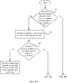
- FIG. 7 is a schematic flowchart of de-isolating an abnormal ONU by an OLT. Specifically, the OLT de-isolates abnormal ONUs one by one. In this embodiment, the OLT de-isolates the abnormal ONU in the following manners: restoring the power remotely supplied to the abnormal ONU, turning on the optical switch corresponding to the abnormal ONU, and indicating the abnormal ONU to send the upstream optical signal.
- the OLT de-isolates a single ONU, and detects whether an upstream optical signal is received in the idle timeslot. If detecting an upstream optical signal in the idle timeslot, the OLT isolates the abnormal ONU again. If detecting no upstream optical signal in the idle timeslot, the OLT determines whether all isolated abnormal ONUs have been processed. If all the isolated abnormal ONUs have been processed, the procedure ends. If all the isolated abnormal ONUs are not processed, the foregoing de-isolation step is repeated.
- FIG. 8A and FIG. 8B are a schematic flowchart of an example of a detection method for a passive optical network. In FIG. 8A and FIG. 8B , the following steps are included.
- Step 301 An OLT stops allocating timeslots to all ONUs, to detect whether there is an abnormal ONU.
- Step 302. The OLT indicates a control unit to turn off all optical switches.
- Step 303 The OLT detects whether an upstream optical signal is received.
- Step 304 The OLT indicates the control unit to turn on the optical switches one by one, and allocates a specified timeslot to an ONU.
- the OLT indicates the control unit to turn on the optical switches one by one, and allocates the specified timeslot to an ONU corresponding to an enabled optical transmission channel.
- a timeslot other than the specified timeslot allocated to the ONU is an idle timeslot. If detecting an upstream optical signal in the idle timeslot, the OLT may determine that the ONU corresponding to the enabled optical transmission channel is an abnormal ONU.
- Step 305 The OLT detects whether an upstream optical signal is received in the idle timeslot.
- the OLT may determine that the ONU corresponding to the enabled optical transmission channel is an abnormal ONU, and perform step 306.
- the OLT performs step 307.
- Step 306. Isolate the abnormal ONU.
- Step 307. The OLT determines whether all the ONUs have been detected.
- FIG. 9A and FIG. 9B are a schematic flowchart of an example of a detection method for a passive optical network.
- the following steps are included.
- Step 401 An OLT stops allocating timeslots to all ONUs, to detect whether there is an abnormal ONU.
- Step 402. The OLT indicates a control unit to turn off all optical switches.
- Step 403. The OLT detects whether an upstream optical signal is received.
- Step 404 The OLT indicates the control unit to turn on the optical switches one by one, and allocates a specified timeslot to the control unit.
- the OLT indicates the control unit to turn on the optical switches one by one, and allocates the specified timeslot to the control unit.
- a timeslot other than the specified timeslot allocated to the control unit is an idle timeslot. If detecting an upstream optical signal in the idle timeslot, the OLT may determine that an ONU corresponding to an enabled optical transmission channel is an abnormal ONU.
- the OLT sends a turn-on instruction 1 to the control unit to instruct the control unit to turn on an optical switch corresponding to an ONU 1.
- the control unit After receiving the instruction, the control unit sends a response signal to the OLT in the specified timeslot corresponding to the control unit, to indicate that the control unit has successfully received the turn-on instruction.
- the OLT needs to preferably check the control unit to determine whether the control unit sends an upstream optical signal in the specified timeslot allocated to the control unit.
- Step 405. The OLT detects whether an upstream optical signal is received in the idle timeslot.
- the OLT may determine that the ONU corresponding to the enabled optical transmission channel is an abnormal ONU, and perform step 406.
- the OLT performs step 407.
- Step 406. Isolate the abnormal ONU.
- Step 407. The OLT determines whether all the ONUs have been detected.
- FIG. 10 is a schematic flowchart of a detection method for a passive optical network according to an embodiment of this application. In FIG. 10 , the following steps are included.
- Step 501 A control unit detects whether communication between the control unit and an OLT is abnormal.
- control unit when the OLT has "downstream light pollution" and/or when the control unit is faulty, communication between the control unit and the OLT is abnormal.
- that the control unit is faulty includes the following: The control unit is faulty for a device reason of the control unit and/or an optical transmission channel between the control unit and the OLT is faulty.
- Step 502. The control unit detects whether the control unit and a link between the control unit and the OLT are in a normal state.
- the control unit determines whether communication is abnormal for a physical or network reason. For example, communication between the control unit and the OLT may be abnormal because the control unit is in an abnormal state, for example, a port is damaged. Alternatively, communication between the control unit and the OLT may be abnormal because the link between the control unit and the OLT is abnormal, for example, the control unit fails to receive a signal of the OLT due to link blocking or the like, and consequently frame loss is caused.
- control unit may detect receive optical power to determine whether the optical signal of the OLT cannot be successfully received for the physical or network reason. In an example, if the receive optical power is normal, the control unit performs step 503. In another example, if the receive optical power is abnormal, the control unit may determine that the control unit and the link between the control unit and the OLT are in the abnormal state, and the control unit may send an alarm to the OLT. It should be noted that if the control unit is faulty for another reason, the control unit may still detect, through self check, that the control unit is in the abnormal state, and report the information to the OLT.
- Step 503. The control unit disables optical transmission channels between an optical splitter and a plurality of ONUs.
- control unit when the control unit detects that communication between the control unit and the OLT is abnormal and the abnormality is not caused by the control unit, the control unit may determine that there is an abnormal ONU that causes the "downstream light pollution" of the OLT.
- Step 504. The control unit enables the optical transmission channels between the optical splitter and the plurality of ONUs one by one to locate the abnormal ONU.
- control unit may turn on optical switches corresponding to the ONUs one by one to enable the optical transmission channels corresponding to the ONUs.
- control unit determines that the ONU is a normal ONU.
- control unit may determine that the ONU interferes with a downstream optical signal of the OLT and the ONU is an abnormal ONU.
- Step 505. Isolate the abnormal ONU.
- an isolation operation performed by the control unit on the ONU includes at least one of the following: cutting off power supplied to the abnormal ONU, and turning off an optical switch corresponding to the abnormal ONU to disable an optical transmission channel corresponding to the ONU.
- a restoring operation performed by the control unit on the abnormal ONU may be independently performed by the control unit.
- the OLT may indicate the control unit to perform the restoring operation.
- Other details of the restoring operation on the abnormal ONU are similar to those in Scenario 1, and are not described herein again.
- FIG. 11 is a schematic flowchart of an example of a detection method for a passive optical network.
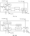
- FIG. 12 may be a schematic diagram depicting a structure of the control unit in the structure of the optical splitter and electrical combiner shown in FIG. 2 .
- the control unit includes but is not limited to a CPU and a PON MAC chip (which may also be referred to as an internal ONU).
- the internal ONU may perform a function of an ONU. For example, after detecting frame loss, the internal ONU may generate a loss of frame (loss of frame, LOF) alarm.
- LOF loss of frame
- the internal ONU is integrated with the CPU, in other words, the internal ONU is integrated into the control unit, so that the CPU can directly read the LOF alarm generated by the internal ONU.
- the CPU may further directly read information such as a loss of signal (Loss of Signal, LOS) alarm and optical power that are generated by the internal ONU.
- LOS Loss of Signal
- Step 601. The control unit detects whether there is an LOF alarm
- the internal ONU fails to receive a signal of the OLT, and generates an LOF alarm.
- the control unit (which is specifically the CPU in the control unit) directly reads the LOF alarm generated by the internal ONU.
- Step 602. The control unit detects whether receive optical power is less than a threshold.
- the CPU in the control unit may directly read the optical power information in the internal ONU to determine whether the receive optical power is less than the threshold. If the receive optical power is less than the threshold, the control unit determines that the control unit is faulty, and sends fault information to the OLT. If the receive optical power is not less than the threshold, the control unit determines that there is an abnormal ONU that causes the downstream light pollution of the OLT, and performs step 603.
- Step 603. The control unit turns off all optical switches.
- Step 604. The control unit detects whether there is an LOF alarm
- control unit may determine that the alarm is caused by a non-ONU, and may report the information to the OLT or directly generate alarm information for detection by an engineer. For example, if receiving no LOF alarm, the control unit may determine that communication between the control unit and the OLT is restored. In other words, communication between the control unit and the OLT is affected by an ONU, and the control unit performs step 605.
- Step 605. The control unit turns on the optical switches one by one.
- Step 606 The control unit detects whether there is an LOF alarm
- the control unit detects whether there is an LOF alarm. If there is an LOF alarm, it indicates that an ONU corresponding to an enabled optical transmission channel is an abnormal ONU, and the control unit performs step 607. If there is no LOF alarm, the control unit may determine that the ONU is a normal ONU, and return to step 605 to continue to check another ONU.
- Step 607. Isolate the abnormal ONU.
- Step 608. The control unit determines whether all the ONUs have been detected.
- control unit checks all the ONUs, that is, if the control unit has isolated the abnormal ONU, communication between the control unit and the OLT is restored. If detecting that all the ONUs are not detected, the control unit returns to step 605 to check another ONU.
- a de-isolation operation on the abnormal ONU may be performed by the OLT.
- Scenario 1 For specific steps, refer to Scenario 1.
- a de-isolation operation on the abnormal ONU may be performed by the control unit. This is not limited in this application.
- FIG. 13 is a schematic flowchart of an example of a detection method for a passive optical network.
- a structure of an optical splitter and electrical combiner shown in FIG. 14 is used as an example for description.
- a control unit and an internal ONU in the optical splitter and electrical combiner are separated from each other, and a CPU in the control unit may be connected to an interface (for example, a network port or a serial port) of the internal ONU through an Ethernet interface.
- a heartbeat detection mechanism may be established between the CPU in the control unit and an OLT by using the internal ONU, to detect whether communication between the control unit and the OLT is normal, so as to determine whether the OLT has downstream light pollution.
- signaling sent by the control unit is sent to the OLT by using the internal ONU.
- the heartbeat detection mechanism may be a bidirectional forwarding detection mechanism. This is not limited in this application.
- Step 701. The control unit detects whether a heartbeat between the control unit and the OLT is normal
- control unit monitors a detection result of the heartbeat between the control unit and the OLT in real time to determine whether communication between the control unit and the OLT is normal.
- control unit performs step 702. If detecting that the heartbeat is normal, the control unit repeatedly performs step 701.
- Step 702. The control unit turns off all optical switches.
- Step 703. The control unit detects whether a heartbeat between the control unit and the OLT is normal
- the control unit determines, by detecting the heartbeat between the control unit and the OLT, whether the downstream light pollution is caused by an abnormal ONU. If the downstream light pollution is caused by an abnormal ONU, the control unit performs step 505. If the downstream light pollution is not caused by an abnormal ONU, the procedure ends.
- Step 704. The control unit turns on the optical switches one by one.
- Step 705. The control unit detects whether a heartbeat between the control unit and the OLT is normal
- the control unit may detect the heartbeat between the control unit and the OLT to determine whether communication between the control unit and the OLT is normal. For example, if the heartbeat between the control unit and the OLT is normal, the control unit determines that communication between the control unit and the OLT is normal, and may determine that an ONU corresponding to an enabled optical transmission channel is a normal ONU and perform step 708. If the heartbeat between the control unit and the OLT is abnormal, the ONU corresponding to the enabled optical transmission channel is an abnormal ONU, and the control unit performs step 707.
- Step 706 Isolate the abnormal ONU.
- Step 707 The control unit determines whether all the ONUs have been detected.
- control unit checks all the ONUs, communication between the control unit and the OLT is restored. If detecting that all the ONUs are not detected, the control unit returns to step 705 to check another ONU.
- a remote power supply manner of the ONU may be as follows:
- the ONU is connected to a power supply unit by using an optical-electrical hybrid cable.
- the optical-electrical hybrid cable includes wires that supply power to the ONU, and further includes the foregoing drop fiber.
- FIG. 15 is a possible schematic diagram depicting a structure of an optical-electrical hybrid cable.
- the optical-electrical hybrid cable includes a fiber (namely, a drop fiber), a wire A, and a wire B.
- the wire A may be configured to be connected to a live wire
- the wire B may be configured to be connected to a neutral wire.
- the wire A may be connected to a -48 V power supply, and the wire B is connected to a 0 V power supply.
- the power supply unit may be integrated with the control unit, or may be independent of the control unit.
- the power supply unit may be disposed in the optical splitter and electrical combiner.
- FIG. 16a and FIG. 16b are schematic diagrams depicting structures of an optical splitter and electrical combiner provided a power supply unit.
- the control unit may control, by using an electrical control port, the power supply unit to supply power or stop supplying power to a remote ONU. Power input of the power supply unit may be from a local power supply of the optical splitter and electrical combiner.
- the power input of the power supply unit may use an uninterruptible power supply (Uninterruptible Power System/Uninterruptible Power Supply, UPS).
- UPS Uninterruptible Power System/Uninterruptible Power Supply
- the UPS remotely supplies power to the ONU by using the power supply unit.
- the power input of the power supply unit may be from a local power supply of an ONU.
- an ONU 1 uses a local power supply manner, and the ONU 1 remotely supplies power to the optical splitter and electrical combiner by using the optical-electrical hybrid cable.
- the control unit may control the power supply unit to stop remotely supplying power to the ONU.
- the ONU cannot be fully isolated when power remotely supplied to the ONU is cut off during isolation. Therefore, another isolation manner needs to be further used. For example, the ONU is indicated to stop sending an upstream optical signal and/or an optical transmission channel is disabled.
- the OLT may still use a conventional-technology solution.
- the OLT sends a TX-stop instruction to each ONU to instruct the ONU to stop sending an upstream optical signal, and sequentially allows the ONUs to send the upstream optical signal, to accurately locate the abnormal ONU by detecting whether there is an upstream optical signal in an idle timeslot.
- this manner may be combined with the power supply manner described in this application to isolate the abnormal ONU.
- the OLT may indicate the control unit to cut off power remotely supplied to the abnormal ONU to isolate the abnormal ONU. It should be noted that a prerequisite for using the isolation manner is that the abnormal ONU does not use the local power supply manner and does not use the UPS power supply manner.
- the OLT and the optical splitter and electrical combiner each include a corresponding hardware structure and/or software module for implementing each function.
- a person skilled in the art should be easily aware that, in combination with units and algorithm steps of the examples described in the embodiments disclosed in this specification, the embodiments of this application may be implemented by hardware or a combination of hardware and computer software. Whether a function is performed by hardware or hardware driven by computer software depends on a particular application and a design constraint condition of the technical solutions. A person skilled in the art may use different methods to implement the described functions for each particular application, but it should not be considered that the implementation goes beyond the scope of this application.
- the electronic device may be divided into functional modules based on the foregoing method examples.
- each functional module may be obtained through division based on each corresponding function, or two or more functions may be integrated into one processing module.
- the integrated module may be implemented in a form of hardware, or may be implemented in a form of a software functional module. It should be noted that in the embodiments of this application, division into the modules is an example and is merely logical function division, and may be other division in an actual implementation.
- FIG. 17 is a possible schematic diagram depicting a structure of an OLT 40 in the foregoing embodiments.
- the OLT may include a processing module 41.
- the module may be configured to: if detecting that there is an abnormal ONU in a plurality of ONUs, disable optical transmission channels between an optical splitter and the plurality of ONUs, and enable the optical transmission channels between the optical splitter and the plurality of ONUs one by one; and in the process of enabling the optical transmission channels between the optical splitter and the plurality of ONUs one by one, if an ONU corresponding to an enabled optical transmission channel does not send an upstream optical signal in a specified timeslot through time division multiplexing, determine that the ONU corresponding to the enabled optical transmission channel is an abnormal ONU.
- the OLT 40 further includes a sending module 42.
- the module may be configured to indicate a control unit to turn off a multiway optical switch, where the control unit is connected to the multiway optical switch and the OLT, the multiway optical switch is configured to be connected to the optical splitter and the plurality of ONUs, each way of the multiway optical switch connects the optical splitter to one of the plurality of ONUs, and each way of the multiway optical switch is configured to control an optical transmission channel corresponding to one of the plurality of ONUs to be enabled and disabled.
- the processing module 41 is configured to enable an optical transmission channel corresponding to a single ONU each time.
- the processing module 41 is further configured to isolate the abnormal ONU.
- the processing module 41 is further configured to: send a TX-stop instruction to the abnormal ONU, where the TX-stop instruction is used to instruct the abnormal ONU to stop sending the upstream optical signal, cut off power remotely supplied to the abnormal ONU, and disable an optical transmission channel between the optical splitter and the abnormal ONU.
- the processing module 41 is further configured to de-isolate the abnormal ONU after predetermined duration.
- the processing module 41 is further configured to: send a TX-permit instruction to the abnormal ONU, where the TX-permit instruction is used to instruct the abnormal ONU to send the optical signal, restore the power remotely supplied to the abnormal ONU, and enable the optical transmission channel between the optical splitter and the abnormal ONU; and if the abnormal ONU sends the upstream optical signal in the specified timeslot through time division multiplexing, determine that the abnormal ONU is restored.
- the multiway optical switch is connected to the plurality of ONUs through drop fibers, the optical transmission channels are borne in the drop fibers, the drop fibers are included in optical-electrical hybrid cables, and the optical-electrical hybrid cable includes wires that remotely supply power to the ONU.
- the wires are connected to a power supply and one or more of the plurality of ONUs.
- FIG. 18 is a possible schematic diagram depicting a structure of a control unit 50 in the foregoing embodiments.
- the control unit 50 may include a processing module 51.
- the module may be configured to: if detecting that communication between the control unit and an optical line terminal OLT is abnormal, disable optical transmission channels between an optical splitter and a plurality of ONUs, and enable the optical transmission channels between the optical splitter and the plurality of ONUs one by one; and in the process of enabling the optical transmission channels between the optical splitter and the plurality of ONUs one by one, if communication between the control unit and the OLT is abnormal, determine that an ONU corresponding to an enabled optical transmission channel is an abnormal ONU.
- the processing module 51 is further configured to determine that the control unit and a physical link between the control unit and the OLT are in a normal state.
- the processing module 51 is further configured to turn off a multiway optical switch, where the multiway optical switch is configured to be connected to the optical splitter and the plurality of ONUs, each way of the multiway optical switch connects the optical splitter to one of the plurality of ONUs, and each way of the multiway optical switch is configured to control an optical transmission channel corresponding to one of the plurality of ONUs to be enabled and disabled.
- the processing module 51 is further configured to enable an optical transmission channel corresponding to a single ONU each time.
- the processing module 51 is further configured to isolate the abnormal ONU.
- the processing module 51 is further configured to: cut off power remotely supplied to the abnormal ONU, and disable an optical transmission channel between the optical splitter and the abnormal ONU.
- the processing module 51 is further configured to de-isolate the abnormal ONU after predetermined duration.
- the processing module 51 is further configured to: restore the power remotely supplied to the abnormal ONU, and/or enable the optical transmission channel between the optical splitter and the abnormal ONU; and if communication between the optical splitter and the OLT is normal after the abnormal ONU is de-isolated, determine that the abnormal ONU is restored.
- an embodiment of this application provides a system, including an OLT, a control unit, and a plurality of ONUs.
- the system may be configured to implement embodiments in Scenario 1 and Scenario 2.
- the apparatus in this application may be used in the technical solution of the foregoing method embodiment. Implementation principles and technical effects of the apparatus are similar to those of the method embodiment, and are not described herein again.
- the apparatus includes a processor 61 and a memory 62.
- the processor 61 is connected to the memory 62 by using a communications bus.
- the memory 62 may include one or more memories.
- the memory may be a component configured to store a program or data in one or more devices or circuits.
- the memory 62 may be standalone, and is connected to the processor 61 through the communications bus.
- the memory 62 may alternatively be integrated with the processor 61.
- the processor 61 may include one or more processors.
- the processor 61 may be configured to execute the program stored in the memory, so that the apparatus implements the method performed by the OLT in the foregoing embodiments.
- the processor 61 may be configured to execute the program stored in the memory, so that the apparatus implements the method performed by the control unit in the foregoing embodiments.
- the apparatus 60 may be the control unit or a chip in the control unit in the embodiments of this application
- the processor 61 may be configured to execute the program stored in the memory, so that the apparatus implements the method performed by the control unit in the foregoing embodiments.
- An embodiment of this application further provides a computer-readable storage medium.
- the method described in the foregoing embodiment may be completely or partially implemented by using software, hardware, firmware, or any combination thereof. If the methods are implemented in software, functions used as one or more instructions or code may be stored in or transmitted on the computer-readable medium.
- the computer-readable medium may include a computer storage medium and a communication medium, and may further include any medium that can transfer a computer program from one place to another.
- the storage medium may be any available medium accessible to a computer.
- the computer-readable medium may include a RAM, a ROM, an EEPROM, a CD-ROM or another optical disc storage, a magnetic disk storage or another magnetic storage device, or any other medium that can be configured to carry or store required program code in a form of an instruction or a data structure and that may be accessed by the computer.
- any connection is appropriately referred to as a computer-readable medium.
- a coaxial cable, an optical fiber cable, a twisted pair, a digital subscriber line (DSL), or wireless technologies are used to transmit software from a website, a server, or another remote source
- the coaxial cable, the optical fiber cable, the twisted pair, the DSL or the wireless technologies such as infrared, radio, and a microwave are included in a definition of the medium.
- Magnetic disks and optical discs used in this specification include a compact disk (CD), a laser disk, an optical disc, a digital versatile disc (DVD), a floppy disk, and a Blu-ray disc.
- the magnetic disks usually magnetically reproduce data, and the optical discs optically reproduce data by using laser light.
- the foregoing combinations should also be included within the scope of the computer-readable medium.
- An embodiment of this application further provides a computer program product.
- the method described in the foregoing embodiment may be completely or partially implemented by using software, hardware, firmware, or any combination thereof.
- the method may be all or partially implemented in a form of a computer program product.
- the computer program product includes one or more computer instructions.
- the foregoing computer program instruction is loaded and executed on a computer, the procedures or functions described in the foregoing method embodiments are all or partially generated.
- the foregoing computer may be a general-purpose computer, a special-purpose computer, a computer network, a network device, user equipment or other programmable apparatuses.
Landscapes
- Engineering & Computer Science (AREA)
- Computer Networks & Wireless Communication (AREA)
- Physics & Mathematics (AREA)
- Electromagnetism (AREA)
- Signal Processing (AREA)
- Optical Communication System (AREA)
- Small-Scale Networks (AREA)
Applications Claiming Priority (2)
| Application Number | Priority Date | Filing Date | Title |
|---|---|---|---|
| CN201911032659.4A CN112738660B (zh) | 2019-10-28 | 2019-10-28 | 无源光网络的检测方法、装置及系统 |
| PCT/CN2020/111062 WO2021082670A1 (fr) | 2019-10-28 | 2020-08-25 | Procédé et appareil de détection de réseau optique passif, et système |
Publications (2)
| Publication Number | Publication Date |
|---|---|
| EP4020839A1 true EP4020839A1 (fr) | 2022-06-29 |
| EP4020839A4 EP4020839A4 (fr) | 2022-10-26 |
Family
ID=75589446
Family Applications (1)
| Application Number | Title | Priority Date | Filing Date |
|---|---|---|---|
| EP20882079.5A Pending EP4020839A4 (fr) | 2019-10-28 | 2020-08-25 | Procédé et appareil de détection de réseau optique passif, et système |
Country Status (3)
| Country | Link |
|---|---|
| EP (1) | EP4020839A4 (fr) |
| CN (1) | CN112738660B (fr) |
| WO (1) | WO2021082670A1 (fr) |
Cited By (5)
| Publication number | Priority date | Publication date | Assignee | Title |
|---|---|---|---|---|
| US20230421934A1 (en) * | 2020-11-25 | 2023-12-28 | Nippon Telegraph And Telephone Corporation | Communication control device, communication control system, communication control method and communication control program |
| EP4576811A4 (fr) * | 2022-12-06 | 2025-12-17 | Huawei Tech Co Ltd | Diviseur optique, passerelle esclave, procédé de communication et système de communication optique |
| EP4572325A4 (fr) * | 2022-12-06 | 2025-12-17 | Huawei Tech Co Ltd | Diviseur optique, passerelle secondaire, procédé de détection et système de communication optique |
| EP4572326A4 (fr) * | 2022-12-06 | 2025-12-24 | Huawei Tech Co Ltd | Diviseur optique, passerelle secondaire, procédé de détection et système de communication optique |
| EP4576705A4 (fr) * | 2022-12-06 | 2025-12-24 | Huawei Tech Co Ltd | Séparateur optique de faisceau, passerelle esclave, passerelle maître et procédé de transmission de signal électrique |
Families Citing this family (5)
| Publication number | Priority date | Publication date | Assignee | Title |
|---|---|---|---|---|
| CN115514626A (zh) * | 2021-06-21 | 2022-12-23 | 中兴通讯股份有限公司 | 故障定位检测方法、根节点、通信系统拓扑和存储介质 |
| CN114696894B (zh) * | 2022-05-31 | 2022-11-08 | 深圳市华迅光通信有限公司 | 无源光网络设备的测试方法、装置及可读存储介质 |
| CN218446090U (zh) * | 2022-08-24 | 2023-02-03 | 华为技术有限公司 | 分光器和光网络系统 |
| CN119450265A (zh) * | 2023-07-31 | 2025-02-14 | 中兴通讯股份有限公司 | 光网络冲突检测方法、装置及存储介质 |
| CN119341921B (zh) * | 2024-10-17 | 2025-10-28 | 广东电网有限责任公司 | 基于硬隔离无源光纤网络的性能分析方法、装置、终端设备及存储介质 |
Family Cites Families (10)
| Publication number | Priority date | Publication date | Assignee | Title |
|---|---|---|---|---|
| CN101047442B (zh) * | 2006-04-02 | 2012-05-30 | 华为技术有限公司 | 一种无源光网络的维护方法及其系统 |
| CN101296034B (zh) * | 2007-04-26 | 2012-07-11 | 华为技术有限公司 | 传输监测信息方法和装置、及无源光网络系统 |
| EP2066046B1 (fr) * | 2007-09-21 | 2015-09-02 | Nokia Solutions and Networks Oy | Séparateur optique à sécurité intégrée et procédé pour isoler des fautes dans un réseau optique passif |
| US8873960B2 (en) * | 2008-12-30 | 2014-10-28 | Broadcom Corporation | Techniques for detecting optical faults in passive optical networks |
| CN101997605B (zh) * | 2009-08-13 | 2015-06-03 | 中兴通讯股份有限公司 | 光分配网络和光网络单元故障处理、注册和物理定位方法 |
| CN102098096B (zh) * | 2009-12-11 | 2016-06-15 | 中兴通讯股份有限公司 | 一种无源光网络中的故障检测方法及系统 |
| CN102201860B (zh) * | 2010-03-24 | 2016-07-06 | 中兴通讯股份有限公司 | 光网络单元异常发光故障隔离系统及方法 |
| CN101984561B (zh) * | 2010-11-15 | 2014-09-10 | 中兴通讯股份有限公司 | 无源光网络光纤故障的检测系统和方法 |
| CN105228183A (zh) * | 2014-06-09 | 2016-01-06 | 中兴通讯股份有限公司 | 上行数据异常处理方法及装置 |
| US10153842B2 (en) * | 2017-02-21 | 2018-12-11 | Verizon Patent And Licensing Inc. | Emulating rogue optical network unit behavior in a passive optical network |
-
2019
- 2019-10-28 CN CN201911032659.4A patent/CN112738660B/zh active Active
-
2020
- 2020-08-25 WO PCT/CN2020/111062 patent/WO2021082670A1/fr not_active Ceased
- 2020-08-25 EP EP20882079.5A patent/EP4020839A4/fr active Pending
Cited By (5)
| Publication number | Priority date | Publication date | Assignee | Title |
|---|---|---|---|---|
| US20230421934A1 (en) * | 2020-11-25 | 2023-12-28 | Nippon Telegraph And Telephone Corporation | Communication control device, communication control system, communication control method and communication control program |
| EP4576811A4 (fr) * | 2022-12-06 | 2025-12-17 | Huawei Tech Co Ltd | Diviseur optique, passerelle esclave, procédé de communication et système de communication optique |
| EP4572325A4 (fr) * | 2022-12-06 | 2025-12-17 | Huawei Tech Co Ltd | Diviseur optique, passerelle secondaire, procédé de détection et système de communication optique |
| EP4572326A4 (fr) * | 2022-12-06 | 2025-12-24 | Huawei Tech Co Ltd | Diviseur optique, passerelle secondaire, procédé de détection et système de communication optique |
| EP4576705A4 (fr) * | 2022-12-06 | 2025-12-24 | Huawei Tech Co Ltd | Séparateur optique de faisceau, passerelle esclave, passerelle maître et procédé de transmission de signal électrique |
Also Published As
| Publication number | Publication date |
|---|---|
| WO2021082670A1 (fr) | 2021-05-06 |
| CN112738660B (zh) | 2022-06-07 |
| CN112738660A (zh) | 2021-04-30 |
| EP4020839A4 (fr) | 2022-10-26 |
Similar Documents
| Publication | Publication Date | Title |
|---|---|---|
| EP4020839A1 (fr) | Procédé et appareil de détection de réseau optique passif, et système | |
| US8655168B2 (en) | Passive optical network maintenance method, an optical network unit, and an optical line terminal | |
| US10129617B2 (en) | Link switching method, device, and system | |
| EP3142312B1 (fr) | Procédés et appareils de traitement d'une anomalie de données montantes | |
| EP2164189A1 (fr) | Système de réseau optique passif et procédé de détermination de défaut | |
| JP6369959B2 (ja) | 光通信システム、局側装置、加入者装置及び光通信方法 | |
| US20150358076A1 (en) | Port-dualized optical line terminal and passive optical network system capable of measuring rssi of standby line in standby port, and method of determining stability of standby line using the same | |
| KR20170093946A (ko) | 불량 광 네트워크 유닛을 검출하는 방법, 장치 및 시스템 | |
| US20140270770A1 (en) | Passive Optical Networking Redundancy Via Two or More Auto Sensing Optical Line Terminals | |
| TW201334438A (zh) | 被動光學網路中提供保護的裝置及方法 | |
| US20140369676A1 (en) | Pon system, olt, and onu | |
| US20180091220A1 (en) | Optical network system | |
| US20250337487A1 (en) | Link switching method and system, electronic device, and storage medium | |
| US12500666B2 (en) | Link status measurement method, apparatus, and system, and storage medium | |
| US20220224595A1 (en) | Optical communication device and control method | |
| CN114584211B (zh) | 一种流氓光网络终端的检测方法及光通信装置 | |
| US10291325B2 (en) | Optical network unit, PON system, and method of controlling optical network unit | |
| US20240413899A1 (en) | Method for managing an operating fault in a laser diode | |
| US20250317199A1 (en) | PON fault notification in a multi-homed protection environment | |
| CN104125008A (zh) | 保护支线的方法及装置 | |
| KR102692596B1 (ko) | 수동형 광 네트워크에서 미인증 회선의 차단을 위한 시스템 및 방법 | |
| KR101459606B1 (ko) | 광 네트워크 이중화를 위한 네트워크 장비 | |
| CN118695139A (zh) | 状态通告方法、装置、光通信系统以及相关设备 |
Legal Events
| Date | Code | Title | Description |
|---|---|---|---|
| STAA | Information on the status of an ep patent application or granted ep patent |
Free format text: STATUS: THE INTERNATIONAL PUBLICATION HAS BEEN MADE |
|
| PUAI | Public reference made under article 153(3) epc to a published international application that has entered the european phase |
Free format text: ORIGINAL CODE: 0009012 |
|
| STAA | Information on the status of an ep patent application or granted ep patent |
Free format text: STATUS: REQUEST FOR EXAMINATION WAS MADE |
|
| 17P | Request for examination filed |
Effective date: 20220321 |
|
| AK | Designated contracting states |
Kind code of ref document: A1 Designated state(s): AL AT BE BG CH CY CZ DE DK EE ES FI FR GB GR HR HU IE IS IT LI LT LU LV MC MK MT NL NO PL PT RO RS SE SI SK SM TR |
|
| A4 | Supplementary search report drawn up and despatched |
Effective date: 20220926 |
|
| RIC1 | Information provided on ipc code assigned before grant |
Ipc: H04Q 11/00 20060101ALI20220920BHEP Ipc: H04B 10/07 20130101AFI20220920BHEP |
|
| DAV | Request for validation of the european patent (deleted) | ||
| DAX | Request for extension of the european patent (deleted) | ||
| STAA | Information on the status of an ep patent application or granted ep patent |
Free format text: STATUS: EXAMINATION IS IN PROGRESS |
|
| 17Q | First examination report despatched |
Effective date: 20251002 |