EP4020855A1 - Procédé et appareil de synchronisation temporelle - Google Patents
Procédé et appareil de synchronisation temporelle Download PDFInfo
- Publication number
- EP4020855A1 EP4020855A1 EP20863754.6A EP20863754A EP4020855A1 EP 4020855 A1 EP4020855 A1 EP 4020855A1 EP 20863754 A EP20863754 A EP 20863754A EP 4020855 A1 EP4020855 A1 EP 4020855A1
- Authority
- EP
- European Patent Office
- Prior art keywords
- time
- artificial intelligence
- intelligence device
- time synchronization
- reference time
- Prior art date
- Legal status (The legal status is an assumption and is not a legal conclusion. Google has not performed a legal analysis and makes no representation as to the accuracy of the status listed.)
- Granted
Links
Images



Classifications
-
- H—ELECTRICITY
- H04—ELECTRIC COMMUNICATION TECHNIQUE
- H04B—TRANSMISSION
- H04B1/00—Details of transmission systems, not covered by a single one of groups H04B3/00 - H04B13/00; Details of transmission systems not characterised by the medium used for transmission
- H04B1/69—Spread spectrum techniques
- H04B1/707—Spread spectrum techniques using direct sequence modulation
- H04B1/7073—Synchronisation aspects
-
- G—PHYSICS
- G04—HOROLOGY
- G04R—RADIO-CONTROLLED TIME-PIECES
- G04R40/00—Correcting the clock frequency
- G04R40/06—Correcting the clock frequency by computing the time value implied by the radio signal
-
- H—ELECTRICITY
- H04—ELECTRIC COMMUNICATION TECHNIQUE
- H04J—MULTIPLEX COMMUNICATION
- H04J3/00—Time-division multiplex systems
- H04J3/02—Details
- H04J3/06—Synchronising arrangements
- H04J3/0635—Clock or time synchronisation in a network
-
- H—ELECTRICITY
- H04—ELECTRIC COMMUNICATION TECHNIQUE
- H04J—MULTIPLEX COMMUNICATION
- H04J3/00—Time-division multiplex systems
- H04J3/02—Details
- H04J3/06—Synchronising arrangements
- H04J3/0635—Clock or time synchronisation in a network
- H04J3/0638—Clock or time synchronisation among nodes; Internode synchronisation
-
- H—ELECTRICITY
- H04—ELECTRIC COMMUNICATION TECHNIQUE
- H04B—TRANSMISSION
- H04B1/00—Details of transmission systems, not covered by a single one of groups H04B3/00 - H04B13/00; Details of transmission systems not characterised by the medium used for transmission
- H04B1/69—Spread spectrum techniques
- H04B2001/6908—Spread spectrum techniques using time hopping
-
- H—ELECTRICITY
- H04—ELECTRIC COMMUNICATION TECHNIQUE
- H04B—TRANSMISSION
- H04B2201/00—Indexing scheme relating to details of transmission systems not covered by a single group of H04B3/00 - H04B13/00
- H04B2201/69—Orthogonal indexing scheme relating to spread spectrum techniques in general
- H04B2201/707—Orthogonal indexing scheme relating to spread spectrum techniques in general relating to direct sequence modulation
- H04B2201/7073—Direct sequence modulation synchronisation
-
- H—ELECTRICITY
- H04—ELECTRIC COMMUNICATION TECHNIQUE
- H04J—MULTIPLEX COMMUNICATION
- H04J3/00—Time-division multiplex systems
- H04J3/02—Details
- H04J3/06—Synchronising arrangements
- H04J3/0635—Clock or time synchronisation in a network
- H04J3/0638—Clock or time synchronisation among nodes; Internode synchronisation
- H04J3/0658—Clock or time synchronisation among packet nodes
- H04J3/0661—Clock or time synchronisation among packet nodes using timestamps
Definitions
- This application relates to the artificial intelligence field, and in particular, to a time synchronization method and apparatus.
- Intelligent control is a key technology in a working process of the artificial intelligent device (for example, an intelligent vehicle, a robot, and an intelligent ship). Accuracy of time synchronization determines reliability of intelligent control.
- a sensor timestamp, sensor data fusion, positioning accuracy compensation, planning decision making, and the like in intelligent control all strongly depend on system time. Therefore, an intelligent control process has a higher requirement for time synchronization.
- a global navigation satellite system (global navigation satellite system, GNSS) module in an intelligent control system receives a satellite timing signal, and obtains accurate time by using the satellite timing signal; and a system time management module uses, as system time, the accurate time obtained by using the satellite timing signal, and completes time synchronization to ensure time accuracy.
- GNSS global navigation satellite system
- the GNSS module When the artificial intelligence device is in a blocking scenario such as a tunnel or a city canyon, the GNSS module cannot obtain the satellite timing signal.
- the system time management module uses time of an internal clock as system time for intelligent control. If the satellite timing signal has been lost for a relatively long time, there is a relatively large time difference between the time of the internal clock and time of a satellite due to insufficient accuracy of the internal clock. Therefore, when the GNSS module re-obtains the satellite timing signal, if accurate time obtained by using the satellite timing signal is directly used as the system time, the system time hops. Once the system time hops, stability of intelligent control is severely affected. For example, there is a case in which a sensor loses a frame, fused data cannot be matched, positioning is inaccurate, or an exception occurs in planning control. Consequently, running of the artificial intelligent device is abnormal
- This application provides a time synchronization method and apparatus, to improve accuracy of time synchronization in the artificial intelligence field and improve stability of intelligent control.
- a time synchronization method is provided and is applied to a time synchronization apparatus in an artificial intelligence device.
- the method may include: determining a time difference between reference time and system time of the artificial intelligence device, where the reference time is timed by an internal clock of the artificial intelligence device and is aligned based on a satellite timing signal, or the reference time is timed by an internal clock of the artificial intelligence device; and adjusting the system time based on a preset step value if the time difference is greater than a preset value.
- determining of the time difference between the reference time and the system time of the artificial intelligence device is added.
- the system time is adjusted based on the preset step value, to implement progressive synchronization. In this way, system time hopping caused by direct alignment performed when the time difference is relatively large is avoided, accuracy of time synchronization in an artificial intelligence field is improved, and stability of intelligent control is improved.
- the artificial intelligence device may specifically include but is not limited to an intelligent vehicle, an intelligent ship, an intelligent robot, and the like.
- the reference time is a reference time value for synchronization of the system time in the time synchronization apparatus.
- the artificial intelligence device can normally receive the satellite timing signal transmitted by a satellite, accurate time obtained by the artificial intelligence device based on the timing signal is used as the reference time.
- the time of the internal clock of the artificial intelligence device is used as the reference time.
- the artificial intelligence device can normally receive the satellite timing signal transmitted by the satellite, the time of the internal clock of the artificial intelligence device may alternatively be aligned with the reference time.
- the preset value is a preconfigured threshold used to determine whether hopping occurs when the reference time is directly synchronized with the system time.
- a specific value of the preset value may be configured based on an actual requirement.
- the preset step value is a preconfigured time adjustment value for progressive synchronization.
- the system time is adjusted to the reference time by one preset step value.
- the time synchronization method provided in this application further includes: redetermining the time difference between the reference time and the system time of the artificial intelligence device after preset duration; and adjusting the system time based on the preset step value if the time difference is greater than the preset value.
- the time synchronization method provided in this application is performed for a plurality of times by setting the preset duration, to implement progressive synchronization.
- the preset duration is less than or equal to a sending period of the satellite timing signal.
- the preset duration may be equal to the sending period of the satellite timing signal. In other words, a time interval of two times of performing the time synchronization method provided in this application is the same as the sending period of the satellite timing signal. Alternatively, the preset duration may be less than the sending period of the satellite timing signal. In other words, a time interval of two times of performing the time synchronization method provided in this application is greater than the sending period of the satellite timing signal, to implement fast synchronization.
- the time synchronization method provided in this application further includes: determining whether the artificial intelligence device enters an intelligent control mode; and if the artificial intelligence device enters the intelligent control mode, determining the time difference between the reference time and the system time of the artificial intelligence device. In this way, a progressive synchronization solution is used only when the artificial intelligence device enters the intelligent control mode, so that processing efficiency is improved.
- the time synchronization method provided in this application further includes: synchronizing the system time with the reference time if the artificial intelligence device does not enter the intelligent control mode.
- Synchronizing the system time with the reference time may be implemented as follows: directly aligning the system time with the reference time.
- the time synchronization method provided in this application further includes: if the time difference between the reference time and the system time of the artificial intelligence device is less than the preset value, synchronizing the system time with the reference time.
- the system time may be adjusted based on the preset step value, or the system time may be synchronized with the reference time.
- the time synchronization method provided in this application may further include: obtaining an initial value of the system time, where the initial value of the system time is reference time when the artificial intelligence device is started.
- this application provides a time synchronization apparatus.
- the apparatus may be an apparatus or a chip system in an artificial intelligence device, or an apparatus that can be used together with an artificial intelligence device.
- the time synchronization apparatus may implement functions performed in the foregoing aspects or possible designs, and the functions may be implemented by hardware, or may be implemented by hardware by executing corresponding software.
- the hardware or the software includes one or more modules corresponding to the functions.
- the time synchronization apparatus may include a determining unit and an adjustment unit.
- the determining unit is configured to determine a time difference between reference time and system time of the artificial intelligence device, where the reference time is timed by an internal clock of the artificial intelligence device and is aligned based on a satellite timing signal, or the reference time is timed by an internal clock of the artificial intelligence device.
- the adjustment unit is configured to adjust the system time based on a preset step value if the time difference determined by the determining unit is greater than a preset value.
- time synchronization apparatus provided in the second aspect is configured to perform the time synchronization method provided in the first aspect.
- time synchronization apparatus provided in the second aspect is configured to perform the time synchronization method provided in the first aspect.
- specific implementation refer to specific implementation of the first aspect.
- an embodiment of this application provides a time synchronization apparatus.
- the time synchronization apparatus may include a processor and a memory.
- the processor is coupled to the memory, and the memory may be configured to store computer program code.
- the computer program code includes computer instructions.
- the time synchronization apparatus is enabled to perform the time synchronization method according to the first aspect or any possible implementation.
- an artificial intelligence device includes the time synchronization apparatus according to any one of the foregoing aspects or possible implementations.
- an embodiment of this application provides a computer-readable storage medium.
- the computer-readable storage medium may include computer software instructions.
- the computer software instructions When the computer software instructions are run on a computer, the computer is enabled to perform the time synchronization method according to any one of the first aspect or the possible implementations of the first aspect.
- an embodiment of this application provides a computer program product.
- the computer program product When the computer program product is run on a computer, the computer is enabled to perform the time synchronization method according to any one of the first aspect of the claims or the possible implementations.
- an embodiment of this application provides a chip system.
- the chip system is applied to an artificial intelligence device, and the chip system includes an interface circuit and a processor.
- the interface circuit is interconnected with the processor by using a line.
- the interface circuit is configured to receive a signal from a memory of the artificial intelligence device, and send the signal to the processor, where the signal includes computer instructions stored in the memory.
- the processor executes the computer instructions, the chip system performs the time synchronization method according to any one of the first aspect or the possible implementations.
- the word “example” or “for example” is used to represent giving an example, an illustration, or a description. Any embodiment or design scheme described as an “example” or with “for example” in embodiments of this application should not be explained as being more preferred or having more advantages than another embodiment or design scheme. Exactly, use of the word such as “example” or “for example” is intended to present a related concept in a specific manner.
- a satellite timing signal may be a signal that is sent by a satellite to indicate accurate time.
- the satellite timing signal includes a time value and a pulse signal.
- a device that receives the satellite timing signal uses a moment of a rising edge of the pulse signal as the time value included in the satellite timing signal, to perform time synchronization.
- the satellite timing signal is periodically sent.
- the satellite in this specification may be Beidou, a global positioning system (Global Positioning System, GPS), a glonass satellite, or the like.
- the reference time may be a reference time value for synchronization of system time in a time synchronization apparatus.
- the artificial intelligence device can normally receive the satellite timing signal transmitted by the satellite, accurate time obtained by the artificial intelligence device based on the timing signal is used as the reference time.
- time of an internal clock of the artificial intelligence device is used as the reference time.
- the time of the internal clock is time recorded by an apparatus with a timing function deployed in the artificial intelligence device.
- the artificial intelligence device can normally receive the satellite timing signal transmitted by the satellite, the time of the internal clock of the artificial intelligence device may alternatively be aligned with the reference time.
- the system time is time information used when the artificial intelligence device performs intelligent control, and the system time is synchronized based on the reference time.
- a GNSS module in the artificial intelligence device receives a satellite timing signal sent by a satellite, to obtain accurate time as a reference signal, and directly synchronizes the system time with the reference signal.
- time of an internal clock is used as the reference signal; in other words, the time of the internal clock is used as the system time.
- timing accuracy of the internal clock is insufficient. Consequently, when the satellite signal is not received in a long time, there is a relatively large time difference between the time of the internal clock and time of the satellite.
- system time hopping is caused if the system time is directly synchronized with the time of the satellite. This affects stability of intelligent control.
- the artificial intelligence device is an intelligent vehicle, and accuracy of an internal clock of the intelligent vehicle is 50 part per million (part per million, PPM).
- PPM part per million
- an internal GNSS module cannot obtain a satellite timing signal. Time of the internal clock is used as a reference signal, and the time of the internal clock is used as the system time.
- a sensor frame rate is as follows: For a camera (camera) sensor, 33 ms is one frame, and for a lidar (lidar) sensor, 50 ms is one frame. If an error between the system time and actual accurate time exceeds specific time, an intelligent control system directly considers that the sensor loses a frame and an alarm is accidentally touched or a function is abnormal. In a fused system of the intelligent vehicle, a camera is fused with a lidar frame within specific time. If the error between the system time and the actual accurate time exceeds the specific time, the intelligent control system cannot select data, and consequently, a fusion function is abnormal.
- the intelligent control system calculates a positioning point by calculating/transmitting time and a speed, an acceleration, and an angular velocity. Once the system time hops, system positioning is abnormal.
- the intelligent control system usually performs planning control at an interval of 10 ms. If the system time hops, next delivery of planning control is abnormal.
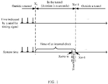
- FIG. 1 shows a time synchronization process in a traveling process of an artificial intelligence device.
- the artificial intelligence device before a moment X 1 timed by a satellite, the artificial intelligence device is located outside a tunnel, and may obtain a satellite timing signal, and system time is synchronous with accurate time indicated by the satellite timing signal.
- the artificial intelligence device enters the tunnel in a second X 1 timed by the satellite, and exits the tunnel in a second Xx+1 timed by the satellite.
- the artificial intelligence device cannot obtain the satellite timing signal, and the system time is time of an internal clock. It is assumed that traveling time of the artificial intelligence device in the tunnel is n seconds, and an accumulated error of internal timing is ⁇ n seconds ( ⁇ is accuracy of the internal clock).
- the system time is a second Xx ⁇ n.
- the artificial intelligence device re-obtains the satellite timing signal in the second Xx+1, and the system time is directly synchronized to the second Xx+1.
- the system time hops from the second Xx ⁇ n to the second Xx+1.
- an embodiment of this application provides a time synchronization method.
- a time difference between reference time and system time of an artificial intelligence device is first determined, and when the time difference is greater than a preset value, the system time is synchronized with the reference time in a stepwise manner, to avoid hopping of the system time, improve accuracy of time synchronization in an artificial intelligence field, and improve stability of intelligent control.
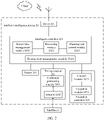
- a time synchronization method provided in embodiments of this application may be applied to a time synchronization system shown in FIG. 2 .
- the time synchronization system may include an artificial intelligence device 20 and a satellite 21.
- the satellite 21 is used for accurate timing and periodically sending a satellite timing signal, to perform time synchronization with the artificial intelligence device 20.
- the artificial intelligence device 20 synchronizes system time with accurate time indicated by the satellite timing signal, to perform intelligent control.
- Actual product forms of the satellite and the artificial intelligence device in the time synchronization system shown in FIG. 2 are not specifically limited.
- the artificial intelligence device 20 may include a server 201, an intelligent controller 202, a sensor 203, a timing receiver 204, and an execution controller 205.
- the server 201 is configured to: connect the artificial intelligence device 20 to the cloud by using a connection medium (wired or wireless, shown as wireless in FIG. 2 ), share information with another artificial intelligence device in the cloud, and cache and process related data.
- a connection medium wireless or wireless, shown as wireless in FIG. 2
- share information with another artificial intelligence device in the cloud and cache and process related data.
- the intelligent controller 202 is configured to implement an intelligent control function of the artificial intelligence device 20.
- the sensor 203 is configured to collect environment data in a running process of the artificial intelligence device 20.
- the sensor 203 may be a millimeter wave radar, a camera, an ultrasonic radar, or a lidar.
- the timing receiver 204 may include a combined positioning module 2041 and an antenna 2042.
- the antenna 2042 is configured to receive the satellite timing signal sent by the satellite 21, and the combined positioning module 2041 obtains the accurate time based on the satellite timing signal.
- the execution controller 205 may include a control module 2051 and an execution module 2052.
- the control module 2051 receives a control signal sent by the intelligent controller 202, and controls the execution module 2052 to implement a function of the artificial intelligence device 20.
- An entity form of the intelligent controller 202 may be shown in FIG. 3 , and includes a processor 301, a memory 302, and an interface module 303.
- the processor 301 may include a system on chip (system on chip, SOC) and a microcontroller unit (microcontroller unit, MCU).
- the memory 302 is configured to store program code, a configuration file, or other content for implementing the intelligent controller 202.
- the interface module 303 is configured to provide a connection interface such as a sensor interface, a controller interface, a gateway interface, or another interface for another device. Specifically, the sensor interface is configured to collect data of each sensor.
- the controller interface is configured to receive and send a related control signal.
- the gateway interface is configured to implement communication between modules by using a network.
- the processor 301 may perform various functions of the intelligent controller 202 by running or executing a software program and/or a module stored in the memory 302 and invoking data stored in the memory 302.
- the intelligent controller 202 may include a sensor time management module 2021, a processing module 2022, a planning and control module 2023, and a system time management module 2024.
- the system time management module 2024 may be deployed inside an MCU or an SOC of the intelligent controller 202.
- the sensor time management module 2021 is separately deployed inside the MCU and the SOC of the intelligent controller 202 based on an attribute of the sensor.
- the processing module 2022 may be deployed inside the SOC of the intelligent controller 202.
- the planning and control module 2023 may be deployed inside the MCU or the SOC of the intelligent controller 202.
- the system time management module 2024 is responsible for overall system time management of the artificial intelligence device 20, including time management of the controller and the sensor.
- the sensor time management module 2021 is mainly responsible for data timestamp management of each frame of the sensor.
- the processing module 2022 may be responsible for receiving the data collected by the sensor 203, and analyzing the data to obtain the environment information, to guide planning and control of the artificial intelligence device 20.
- the planning and control module 2023 is mainly configured to: make a behavior decision based on information provided by the processing module 2022, generate a control instruction, and transmit the control instruction to the execution controller 205.
- An intelligent vehicle is used as an example of the artificial intelligence device 20 below to describe in detail functions of the components of the artificial intelligence device 20.
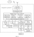
- FIG. 4 is a schematic diagram of a system architecture in an intelligent driving scenario according to an embodiment of this application.
- the system architecture may include an intelligent driving vehicle 40 and a satellite 41.
- the intelligent driving vehicle 40 may include a server 401, an intelligent driving domain controller 402, a sensor 403, a timing receiver 404, and an execution controller 405.
- the server 401, the intelligent driving domain controller 402, the sensor 403, the timing receiver 404, and the execution controller 405 are deployed inside an intelligent driving system.
- the satellite 41 may be a GNSS global satellite navigation system, and includes a glonass, a GPS, and Beidou.
- the server 201 in FIG. 2 may be the server 401 in FIG. 4 .
- the server 401 may specifically include a telematics box (telematics box, TBOX) 4011 and a central gateway 4012.
- TBOX telematics box
- the intelligent controller 202 in FIG. 2 may be the intelligent driving domain controller 402 in FIG. 4 .
- the intelligent driving domain controller 202 may specifically include a sensor time management module 4021, a perception and fusion module 4022, a positioning software module 4023, a road planning and control module 4024, and a system time management module 4025.
- the sensor 203 in FIG. 2 may be the sensor 403 in FIG. 4 .
- the sensor 403 may specifically include a millimeter wave radar 4031, a camera 4032, a lidar 4033, and an ultrasonic radar 4034.
- the timing receiver 204 in FIG. 2 may be the timing receiver 404 in FIG. 4 .
- the timing receiver 404 may specifically include a combined positioning module 4041 and an antenna 4042.
- the execution controller 205 in FIG. 2 may be the execution controller 405 in FIG. 4 .
- the execution controller 405 may specifically include a chassis electronic control unit 4051, a steering system 4052, and a wheel speedometer 4053.
- the TBOX 4011 is mainly responsible for storing and processing cloud data received by the intelligent driving vehicle 40.
- the central gateway 4012 is mainly responsible for communication between the intelligent driving vehicle 40 and the cloud.
- the sensor time management module 4021 is mainly responsible for data timestamp management of each frame of the sensor 403.
- the perception and fusion module 4022 is divided into two parts: perception and fusion.
- Perception is mainly responsible for intelligent analysis of lidar point cloud data and camera image frame data that are input by a preprocessing module, and implements functions such as static/dynamic target object detection and tracking, lane line identification, traffic light identification, and obstacle identification.
- a fusion unit is configured to: receive an obstacle list, depth information, lane line information, and travelable area information from a perception module, output obstacle state estimation and track prediction in a range of interest through smoothing processing, and output a final travelable area and obstacle information to a planning decision making unit.
- the positioning software module 4023 is mainly responsible for receiving road feature information provided by the perception and fusion module, and outputting spatial positioning and posture information of the vehicle with reference to the GNSS and wheel speedometer fusion positioning information and high-precision map information.
- the road planning and control module 4024 mainly makes a behavior decision based on the travelable area information, the positioning information, and the obstacle information that are provided by the perception and fusion module 4022 and the positioning software module 4023 and real-time motion information of the vehicle, including horizontal and vertical motion control and planning; and generates a control instruction (including a brake, a throttle, a steering wheel, a gear, a steering lamp, and the like) based on motion control and planning and a given speed.
- a control instruction including a brake, a throttle, a steering wheel, a gear, a steering lamp, and the like
- the system time management module 4025 is mainly responsible for overall time management of a driving system, including time management of the controller and the sensor.
- the camera 4032 is mainly responsible for collecting picture information in an environment.
- the millimeter wave radar 4031, the lidar 4033, and the ultrasonic radar 4034 are mainly responsible for collecting object information in the environment.
- the antenna 4042 is mainly responsible for receiving a timing signal transmitted by the satellite.
- the combined positioning module 4041 is mainly responsible for obtaining accurate time based on the satellite timing signal.
- the chassis electronic control unit 4051 is mainly responsible for receiving a control signal sent by the intelligent driving domain controller 402, and controlling the steering system 4052.
- the steering system 4052 is mainly responsible for performing an action based on an instruction of the chassis electronic control unit 4051.
- the wheel speedometer 4053 is mainly responsible for detecting and controlling a rotational speed of a wheel.
- a time synchronization procedure of the system architecture shown in FIG. 4 is as follows:
- the satellite 41 sends a satellite timing signal to the intelligent driving vehicle 40.
- the antenna 4042 in the timing receiver 404 in the system of the intelligent driving vehicle 40 transmits received satellite timing information to the combined positioning module 4041 in the timing receiver 404.
- the combined positioning module 4041 obtains, through parsing, accurate time indicated by the satellite timing information, and sends the accurate time to the system time management module 4025 in the intelligent driving domain controller 402 as system time.
- the system time is specifically used in each module in the intelligent driving domain controller 402 for time management and intelligent control.
- the sensor time management module 4021 performs data timestamp management for each frame of each sensor (the millimeter wave radar 4031, the camera 4032, the lidar 4033, and the ultrasonic radar 4034) based on the system time.
- the perception and fusion module 4022 performs intelligent analysis on input point cloud data and image frame data, completes functions such as static/dynamic target object monitoring and tracking, lane line identification, traffic light identification, and obstacle identification with reference to the system time, and outputs obstacle status estimation, track prediction, and a travelable area in a range of interest.
- the positioning software module 4023 outputs spatial positioning and posture information of the vehicle by combining received road feature information provided by the perception and fusion module with the positioning information and the high-precision map information.
- the road planning and control module 4024 makes a behavior decision based on the travelable area information, the positioning information, and the obstacle information that are provided by the fusion unit and the positioning unit and the real-time motion information of the vehicle, including horizontal and vertical motion control and planning; and generates a control instruction (including a brake, a throttle, a steering wheel, a gear, a steering lamp, and the like) based on motion control and planning and a given speed.
- the generated control instruction is sent to the execution controller 405, and the chassis electronic control unit 4051 in the execution controller 405 controls the steering system 4052 and the like.
- an embodiment of this application provides a time synchronization apparatus, configured to perform the time synchronization method provided in this application.
- the time synchronization apparatus may be deployed in the artificial intelligence device in the time synchronization system shown in FIG. 2 .
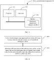
- FIG. 5 shows a time synchronization apparatus 50 related to embodiments of this application.
- the time synchronization apparatus 50 may include a processor 501, a memory 502, and a transceiver 503.
- the memory 502 may be a volatile memory (volatile memory), such as a random access memory (random access memory, RAM); or a nonvolatile memory (non-volatile memory), such as a read-only memory (read-only memory, ROM), a flash memory (flash memory), a hard disk drive (hard disk drive, HDD), or a solid-state drive (solid-state drive, SSD), or a combination of the foregoing types of memories, configured to store program code, a configuration file, or other content that can implement the method in this application.
- volatile memory such as a random access memory (random access memory, RAM)
- nonvolatile memory non-volatile memory
- ROM read-only memory
- flash memory flash memory
- HDD hard disk drive
- SSD solid-state drive
- the processor 501 is a control center of the time synchronization apparatus 50.
- the processor 501 may be a central processing unit (central processing unit, CPU), or may be an application specific integrated circuit (application specific integrated circuit, ASIC), or may be configured as one or more integrated circuits implementing embodiments of this application, for example, one or more microprocessors (digital signal processor, DSP), or one or more field programmable gate arrays (field programmable gate array, FPGA).
- the transceiver 503 is configured to communicate with another device.
- the processor 501 performs the following functions by running or executing an application program and a configuration file and/or a module that are stored in the memory 502, and/or by invoking data stored in the memory 502: determining a time difference between reference time and system time of an artificial intelligence device, where the reference time is timed by an internal clock of the artificial intelligence device and is aligned based on a satellite timing signal, or the reference time is timed by an internal clock of the artificial intelligence device; and adjusting the system time based on a preset step value if the time difference is greater than a preset value.
- an embodiment of this application provides a time synchronization method.
- the time synchronization method is performed by the foregoing time synchronization apparatus, and the time synchronization apparatus may be deployed in the foregoing artificial intelligence device.
- the time synchronization method provided in this embodiment of this application may include the following steps.
- a time synchronization apparatus determines a time difference between reference time and system time of an artificial intelligence device.
- the reference time is timed by an internal clock of the artificial intelligence device and is aligned based on a satellite timing signal, or the reference time is timed by an internal clock of the artificial intelligence device.
- the reference time is a reference time value for synchronization of the system time in the time synchronization apparatus.
- the artificial intelligence device can normally receive the satellite timing signal transmitted by a satellite, accurate time obtained by the artificial intelligence device based on the timing signal is used as the reference time.
- the time of the internal clock of the artificial intelligence device is used as the reference time.
- the time synchronization apparatus performs S601 at a moment A.
- the time synchronization apparatus calculates a difference between reference time at the moment A and system time at the moment A to obtain a time difference C between the reference time and the system time of the artificial intelligence device.
- the preset step value is less than the preset value.
- the preset value is a preconfigured threshold used to determine whether hopping occurs when the reference time is directly synchronized with the system time. In actual application, a specific value of the preset value may be configured based on an actual requirement.
- the preset value may be a fixed value that is set by a user based on experience, or the preset value may be calculated based on a minimum tolerance time variation value of each module in a system.
- the preset step value is each preconfigured time adjustment value for progressive synchronization.
- the system time is adjusted to the reference time by one preset step value.
- the user may set a fixed preset step value based on experience.
- the preset step value may be a dynamic value calculated based on the time difference obtained in S601.
- a specific calculation manner may be: performing calculation based on a preset expression, and the preset expression may be a linear expression or another expression. This is not specifically limited in this embodiment of this application.
- the time synchronization apparatus may adjust the system time at the moment A to the reference time at the moment A by ⁇ .
- the adjustment described herein may be "increase” or "decrease".
- the time synchronization apparatus may increase the system time at the moment A by ⁇ .
- the time synchronization apparatus may decrease the system time at the moment A by ⁇ .
- the system time needs to be initialized to obtain an initial value of the system time.
- the initial value of the system time is reference time when the artificial intelligence device is started.
- determining of the time difference between the reference time and the system time of the artificial intelligence device is added.
- the system time is adjusted based on the preset step value, to implement progressive synchronization. In this way, system time hopping caused by direct alignment performed when the time difference is relatively large is avoided, accuracy of time synchronization in an artificial intelligence field is improved, and stability of intelligent control is improved.
- the time synchronization method provided in this embodiment of this application may further include S602a.
- the time synchronization apparatus determines a magnitude relationship between the preset value and the time difference between the reference time and the system time of the artificial intelligence device.
- the magnitude relationship includes “greater than”, “equal to”, or “less than”.
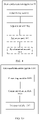
- S602 is performed; if it is determined in S602a that the time difference between the reference time and the system time of the artificial intelligence device is greater than the preset value, S602 is performed; if it is determined in S602a that the time difference between the reference time and the system time of the artificial intelligence device is less than the preset value, S603 is performed; or if it is determined in S602a that the time difference between the reference time and the system time of the artificial intelligence device is equal to the preset value, S602 or S603 is performed.
- the time synchronization apparatus synchronizes the system time with the reference time.
- That the time synchronization apparatus synchronizes the system time with the reference time in S603 may be specifically implemented as follows: The time synchronization apparatus uses the reference time as the system time.
- the preset value is ⁇ . If the time difference C obtained by the time synchronization apparatus in S601 is less than ⁇ , in S602, the time synchronization apparatus may use the reference time at the moment A as the system time at the moment A.
- the time synchronization method provided in this embodiment of this application may further include S601a.
- S601a The time synchronization apparatus determines whether the artificial intelligence device enters an intelligent control mode.
- the time synchronization apparatus may query status information recorded by the artificial intelligence device, to determine whether the artificial intelligence device enters the intelligent control mode.
- the time synchronization apparatus determines, in S601a, that the artificial intelligence device enters the intelligent control mode, S601 is performed; or if the time synchronization apparatus determines, in S601a, that the artificial intelligence device does not enter the intelligent control mode, the time synchronization apparatus directly performs S603 to synchronize the system time with the reference time.
- time synchronization apparatus may perform, for a plurality of times, the time synchronization method provided in this embodiment of this application. Operations in all times of execution are the same, but only system time and reference time in all times of execution are currently the latest. Details are not described again.
- the time synchronization apparatus may re-perform S601 or S601a and subsequent steps to perform next synchronization.
- the system time and the reference time for calculating the time difference are the system time and the reference time in S601.
- the time synchronization apparatus may re-perform, after preset duration, S601 or S601a and subsequent steps to perform next synchronization.
- the preset duration may be less than or equal to a sending period of the satellite timing signal.
- the preset duration is equal to the sending period of the satellite timing signal.
- a time interval of two times of performing the time synchronization method provided in this application is the same as the sending period of the satellite timing signal.
- the sending period of the satellite timing signal may be once per second, and in this case, the preset duration may be one second.
- the preset duration is less than the sending period of the satellite timing signal.
- a time interval of two times of performing the time synchronization method provided in this application is greater than the sending period of the satellite timing signal, to implement fast synchronization.
- the sending period of the satellite timing signal may be once per second, and the preset duration may be 100 milliseconds.
- a value of the preset duration may be configured based on an actual requirement. This is not specifically limited in this embodiment of this application.
- An intelligent vehicle is used as an example of the artificial intelligence device below to describe, with reference to a specific intelligent driving scenario, the time synchronization method provided in this embodiment of this application.
- FIG. 8 shows a time synchronization process in a traveling process of an intelligent vehicle.
- the intelligent vehicle before a moment X 1 timed by a satellite, the intelligent vehicle is located outside a tunnel, and may obtain a satellite timing signal, and system time is synchronous with accurate time indicated by the satellite timing signal.
- the intelligent vehicle enters the tunnel in a second X 1 timed by the satellite, and exits the tunnel in a second Xx timed by the satellite.
- the artificial intelligence device cannot obtain the satellite timing signal, and system time is time of an internal clock. It is assumed that traveling time of the artificial intelligence device in the tunnel is n seconds, and an accumulated error of internal timing is ⁇ a ⁇ n seconds ( ⁇ is accuracy of the internal clock).
- the system time In a second Xx, the system time is a second Xx ⁇ n.
- the intelligent vehicle re-obtains the satellite timing signal in a second Xx+1 timed by the satellite.
- reference time is the second Xx+1
- system time is the second (Xx ⁇ n).
- a time synchronization apparatus deployed in the intelligent vehicle performs the time synchronization method provided in this application, determines a time difference between the reference time, namely, the second Xx+1, and the system time (Xx ⁇ n), and determines a magnitude relationship between the time difference and a preset value ⁇ .
- the time synchronization apparatus determines that the time difference is greater than the preset value ⁇ , as shown in FIG. 8 , the time synchronization apparatus adjusts the system time from (Xx ⁇ n) to the reference time, namely, the second Xx+1, by ⁇ , and adjusts the system time to (Xx ⁇ n) ⁇ .
- the time synchronization apparatus After preset duration t, the time synchronization apparatus provided in this application redetermines a time difference between reference time, namely, a second Xx+t, and system time (Xx ⁇ n) ⁇ +t, determines a magnitude relationship between the time difference and the preset value ⁇ , and if the time difference is greater than the preset value ⁇ , adjusts the system time from (Xx ⁇ n) ⁇ +t to the reference time, namely, the second Xx+t, by ⁇ .
- the time synchronization apparatus determines that a time difference between reference time, namely, the second Xx+m, and system time at this moment is less than the preset value ⁇ , and the time synchronization apparatus synchronizes the system time to the reference time, namely, the second Xx+m.
- t may be less than or equal to a sending period of the satellite timing signal.
- the artificial intelligence device includes a corresponding hardware structure and/or a corresponding software module that perform various functions.
- a person of ordinary skill in the art should easily be aware that, in combination with the examples described in embodiments disclosed in this specification, this application may be implemented by hardware or a combination of hardware and computer software. Whether a function is performed by hardware or hardware driven by computer software depends on a particular application and a design constraint of the technical solutions. A person skilled in the art may use different methods to implement the described functions for each particular application, but it should not be considered that the implementation goes beyond the scope of this application.
- the artificial intelligence device may be divided into function modules based on the foregoing method examples.
- each function module corresponding to each function may be obtained through division, or two or more functions may be integrated into one processing module.
- the integrated module may be implemented in a form of hardware, or may be implemented in a form of a software functional module.
- module division is an example, and is merely a logical function division. In an actual implementation, another division manner may be used.
- FIG. 9 shows a time synchronization apparatus 90 according to an embodiment of this application, and the time synchronization apparatus 90 is configured to implement a function of the artificial intelligence device in the foregoing method.
- the time synchronization apparatus 90 may be an apparatus in the artificial intelligence device, or may be an apparatus that can be used together with the artificial intelligence device.
- the time synchronization apparatus 90 may alternatively be a chip system. In this embodiment of this application, the chip system may include a chip, or may include a chip and another discrete component.
- the time synchronization apparatus 90 may include a determining unit 901 and an adjustment unit 902.
- the determining unit 901 is configured to perform S601 in FIG. 6 or S601 in FIG.
- the adjustment unit 902 is configured to perform S602 in FIG. 6 or S602 in FIG. 7 . All related content of the steps in the foregoing method embodiments may be cited in function descriptions of corresponding function modules. Details are not described herein again.
- the time synchronization apparatus 90 may further include a judgment unit 903, configured to perform step S601a in FIG. 7 , and may further include a synchronization unit 904, configured to perform step S603 in FIG. 7 .
- FIG. 10 shows a time synchronization apparatus 100 according to an embodiment of this application, and the time synchronization apparatus 100 is configured to implement a time synchronization function of the artificial intelligence device in the foregoing method.
- the time synchronization apparatus 100 may be an apparatus in the artificial intelligence device, or may be an apparatus that can be used together with the artificial intelligence device.
- the time synchronization apparatus 100 may be a chip system.
- the time synchronization apparatus 100 includes at least one processing module 1001, configured to implement a time synchronization function of the artificial intelligence device in the methods provided in embodiments of this application.
- the processing module 1001 may be configured to perform processes S601, S601a, S602, S602a, and S603 in FIG. 6 or FIG. 7 .
- the processing module 1001 may be configured to perform processes S601, S601a, S602, S602a, and S603 in FIG. 6 or FIG. 7 .
- the time synchronization apparatus 100 may further include at least one storage module 1002, configured to store program instructions and/or data.
- the storage module 1002 is coupled to the processing module 1001.
- the coupling in this embodiment of this application may be an indirect coupling or a communication connection between apparatuses, units, or modules in an electrical form, a mechanical form, or another form, and is used for information exchange between the apparatuses, the units, or the modules.
- the processing module 1001 may cooperate with the storage module 1002.
- the processing module 1001 may execute the program instructions stored in the storage module 1002. At least one of the at least one storage module may be included in the processing module.
- the time synchronization apparatus 100 may further include a communication module 1003, configured to communicate with another device by using a transmission medium, so that an apparatus used in the time synchronization apparatus 100 may communicate with another device.
- the processing module 1001 is a processor
- the storage module 1002 is a memory
- the communication module 1003 is a transceiver
- the time synchronization apparatus 100 in FIG. 10 in this embodiment of this application may be the time synchronization apparatus shown in FIG. 5 .
- the time synchronization apparatus 90 or the time synchronization apparatus 100 provided in embodiments of this application may be configured to implement functions of the electronic device in the methods implemented in embodiments of this application.
- the time synchronization apparatus 90 or the time synchronization apparatus 100 provided in embodiments of this application may be configured to implement functions of the electronic device in the methods implemented in embodiments of this application.
- the time synchronization apparatus 90 or the time synchronization apparatus 100 provided in embodiments of this application may be configured to implement functions of the electronic device in the methods implemented in embodiments of this application.
- the time synchronization apparatus 90 or the time synchronization apparatus 100 may be configured to implement functions of the electronic device in the methods implemented in embodiments of this application.
- only a part related to embodiments of this application is shown.
- Some other embodiments of this application further provide a computer-readable storage medium.
- the computer-readable storage medium may include computer software instructions.
- the electronic device is enabled to perform the steps performed by the artificial intelligence device in the foregoing embodiment shown in FIG. 6 or FIG. 7 .
- Some other embodiments of this application further provide a computer program product.
- the computer program product When the computer program product is run on a computer, the computer is enabled to perform the steps performed by the artificial intelligence device in the foregoing embodiment shown in FIG. 6 or FIG. 7 .
- Some other embodiments of this application further provide a chip system, and the chip system may be applied to an artificial intelligence device.
- the electronic device includes a display and a camera.
- the chip system includes an interface circuit and a processor.
- the interface circuit is interconnected with the processor by using a line.
- the interface circuit is configured to receive a signal from a memory of the artificial intelligence device, and send the signal to the processor, where the signal includes computer instructions stored in the memory.
- the chip system performs the steps performed by the electronic device in the foregoing embodiment shown in FIG. 6 or FIG. 7 .
- the disclosed apparatus and method may be implemented in other manners.
- the described apparatus embodiments are merely examples.
- division of the modules or units is merely logical function division, and may be other division during actual implementation.
- a plurality of units or components may be combined or may be integrated into another apparatus, or some features may be ignored or not performed.
- displayed or discussed mutual couplings or direct couplings or communication connections may be implemented through some interfaces.
- the indirect couplings or communication connections between the apparatuses or units may be implemented in electrical, mechanical, or other forms.
- the units described as discrete components may or may not be physically separate, and components displayed as units may be one or more physical units, that is, may be located in one place, or may be distributed to a plurality of different places. Some or all of the units may be selected based on actual requirements to achieve the objectives of the solutions of the embodiments.
- function units in embodiments of this application may be integrated into one processing unit, or each of the units may exist alone physically, or two or more units may be integrated into one unit.
- the integrated unit may be implemented in a form of hardware, or may be implemented in a form of a software function unit.
- the integrated unit When the integrated unit is implemented in the form of a software function unit and sold or used as an independent product, the integrated unit may be stored in a readable storage medium. Based on such an understanding, the technical solutions in embodiments of this application essentially, or the part contributing to the current technology, or all or some of the technical solutions may be implemented in a form of a software product.
- the software product is stored in a storage medium and includes several instructions for instructing a device (which may be a single-chip microcomputer, a chip, or the like) or a processor (processor) to perform all or some of the steps of the methods described in embodiments of this application.
- the foregoing storage medium includes: any medium that can store program code, such as a USB flash drive, a removable hard disk, a read-only memory (Read-Only Memory, ROM), a random access memory (Random Access Memory, RAM), a diskette, or an optical disc.
- program code such as a USB flash drive, a removable hard disk, a read-only memory (Read-Only Memory, ROM), a random access memory (Random Access Memory, RAM), a diskette, or an optical disc.
Landscapes
- Engineering & Computer Science (AREA)
- Physics & Mathematics (AREA)
- Computer Networks & Wireless Communication (AREA)
- Signal Processing (AREA)
- Mathematical Physics (AREA)
- Theoretical Computer Science (AREA)
- General Physics & Mathematics (AREA)
- Synchronisation In Digital Transmission Systems (AREA)
- Electric Clocks (AREA)
- Position Fixing By Use Of Radio Waves (AREA)
Applications Claiming Priority (2)
| Application Number | Priority Date | Filing Date | Title |
|---|---|---|---|
| CN201910866525.6A CN110620632B (zh) | 2019-09-12 | 2019-09-12 | 一种时间同步方法及装置 |
| PCT/CN2020/101113 WO2021047271A1 (fr) | 2019-09-12 | 2020-07-09 | Procédé et appareil de synchronisation temporelle |
Publications (4)
| Publication Number | Publication Date |
|---|---|
| EP4020855A1 true EP4020855A1 (fr) | 2022-06-29 |
| EP4020855A4 EP4020855A4 (fr) | 2022-11-16 |
| EP4020855C0 EP4020855C0 (fr) | 2025-08-20 |
| EP4020855B1 EP4020855B1 (fr) | 2025-08-20 |
Family
ID=68923280
Family Applications (1)
| Application Number | Title | Priority Date | Filing Date |
|---|---|---|---|
| EP20863754.6A Active EP4020855B1 (fr) | 2019-09-12 | 2020-07-09 | Procédé et appareil de synchronisation temporelle |
Country Status (4)
| Country | Link |
|---|---|
| US (1) | US11929777B2 (fr) |
| EP (1) | EP4020855B1 (fr) |
| CN (1) | CN110620632B (fr) |
| WO (1) | WO2021047271A1 (fr) |
Families Citing this family (15)
| Publication number | Priority date | Publication date | Assignee | Title |
|---|---|---|---|---|
| CN109668742B (zh) * | 2019-02-20 | 2020-04-28 | 苏州风图智能科技有限公司 | 基于激光雷达的无人车辆的测试方法及装置 |
| CN110620632B (zh) * | 2019-09-12 | 2021-02-23 | 华为技术有限公司 | 一种时间同步方法及装置 |
| CN114124274A (zh) * | 2020-08-31 | 2022-03-01 | 华为技术有限公司 | 一种方法和装置 |
| CN112597635B (zh) * | 2020-12-09 | 2024-12-03 | 友道科技有限公司 | 基于cbtc仿真系统的虚拟时钟系统的生成方法、装置及设备 |
| CN114647179A (zh) * | 2020-12-18 | 2022-06-21 | 华为技术有限公司 | 主时钟装置、从时钟装置和时间同步方法 |
| CN113890665A (zh) * | 2021-09-23 | 2022-01-04 | 北京超星未来科技有限公司 | 一种时间同步方法、系统、存储介质及处理器 |
| EP4380257A4 (fr) * | 2021-09-24 | 2024-08-07 | Huawei Technologies Co., Ltd. | Procédé de synchronisation temporelle et appareil associé |
| CN114460833B (zh) * | 2022-01-24 | 2023-09-08 | 同济大学 | 驾驶设备及其授时方法、地面信号设备以及授时系统 |
| WO2023205444A1 (fr) * | 2022-04-22 | 2023-10-26 | Velo.Ai, Inc. | Système de sécurité de mobilité artificiellement intelligent |
| CN114842075B (zh) * | 2022-06-30 | 2023-02-28 | 小米汽车科技有限公司 | 数据标注方法、装置、存储介质及车辆 |
| US20240118377A1 (en) * | 2022-10-11 | 2024-04-11 | Charter Communications Operating, Llc | Determination of communication device location in a wireless network |
| CN115991203B (zh) * | 2022-12-20 | 2026-02-27 | 东风悦享科技有限公司 | 一种无人集卡自动驾驶系统时间同步系统及方法 |
| CN118282557A (zh) * | 2024-03-29 | 2024-07-02 | 上海海事大学 | 一种时钟回退或前调的检测及自适应时间校正方法 |
| CN119723916B (zh) * | 2024-12-27 | 2025-11-07 | 江苏航天大为科技股份有限公司 | 一种交通信号灯的授时时间调整方法 |
| CN119995695B (zh) * | 2025-04-15 | 2025-10-28 | 中国星网网络系统研究院有限公司 | 卫星时频基准小步调频功能的测试方法及测试系统 |
Family Cites Families (17)
| Publication number | Priority date | Publication date | Assignee | Title |
|---|---|---|---|---|
| US8867520B2 (en) * | 2008-03-07 | 2014-10-21 | Charles Nicholls | Using a network frequency reference to augment timing Synchronization in a wireless base station |
| CN101582790B (zh) * | 2008-05-15 | 2011-12-07 | 华为技术有限公司 | 动态数据稽核以及业务实体故障检测的方法、装置和系统 |
| CN101442799B (zh) * | 2008-12-17 | 2010-12-01 | 广州市新邮通信设备有限公司 | 一种实现终端同步网络侧系统时间的方法、系统及装置 |
| CN101754098B (zh) * | 2008-12-18 | 2013-04-03 | 电信科学技术研究院 | 一种系统时间通知方法、系统及装置 |
| US9088390B1 (en) * | 2013-03-15 | 2015-07-21 | Arris Enterprises, Inc. | Re-synchronization of timing between communication devices |
| JP6079879B2 (ja) * | 2013-06-12 | 2017-02-15 | 富士電機株式会社 | 配信装置、配信システム及び配信方法 |
| US9813173B2 (en) * | 2014-10-06 | 2017-11-07 | Schweitzer Engineering Laboratories, Inc. | Time signal verification and distribution |
| US10310091B2 (en) * | 2015-01-31 | 2019-06-04 | Southwest Research Institute | GPS-based time stamp system |
| CN105388751B (zh) * | 2015-11-26 | 2019-04-05 | 株洲南车时代电气股份有限公司 | 一种用于动车组中防时钟跳变的方法与系统 |
| CN106712884B (zh) * | 2016-11-21 | 2019-03-19 | 广州视源电子科技股份有限公司 | 一种穿戴设备的时间同步校正方法及装置 |
| CN121212197A (zh) * | 2017-05-03 | 2025-12-26 | 弗吉尼亚科技知识产权有限公司 | 自适应无线通信的学习与部署 |
| CN107222281B (zh) * | 2017-06-29 | 2019-03-29 | 广州北极瑞光电子科技有限公司 | 一种在时间同步系统中的智能渐进式秒信号恢复方法 |
| CN109283829B (zh) * | 2018-12-11 | 2020-09-18 | 烟台钟表研究所有限公司 | 一种区域时钟系统的控制方法 |
| CN109687868A (zh) * | 2018-12-28 | 2019-04-26 | 武汉依迅电子信息技术有限公司 | 多参考源的时间同步方法及装置 |
| CN110061797A (zh) * | 2019-05-29 | 2019-07-26 | 海尔优家智能科技(北京)有限公司 | 时间同步方法、装置、存储介质及计算机设备 |
| CN110620632B (zh) * | 2019-09-12 | 2021-02-23 | 华为技术有限公司 | 一种时间同步方法及装置 |
| CN114079942A (zh) * | 2020-08-17 | 2022-02-22 | 索尼公司 | 用于无线通信的电子设备和方法、计算机可读存储介质 |
-
2019
- 2019-09-12 CN CN201910866525.6A patent/CN110620632B/zh active Active
-
2020
- 2020-07-09 EP EP20863754.6A patent/EP4020855B1/fr active Active
- 2020-07-09 WO PCT/CN2020/101113 patent/WO2021047271A1/fr not_active Ceased
-
2022
- 2022-03-11 US US17/692,801 patent/US11929777B2/en active Active
Also Published As
| Publication number | Publication date |
|---|---|
| EP4020855C0 (fr) | 2025-08-20 |
| CN110620632A (zh) | 2019-12-27 |
| US20220200653A1 (en) | 2022-06-23 |
| EP4020855A4 (fr) | 2022-11-16 |
| CN110620632B (zh) | 2021-02-23 |
| EP4020855B1 (fr) | 2025-08-20 |
| US11929777B2 (en) | 2024-03-12 |
| WO2021047271A1 (fr) | 2021-03-18 |
Similar Documents
| Publication | Publication Date | Title |
|---|---|---|
| EP4020855B1 (fr) | Procédé et appareil de synchronisation temporelle | |
| EP3614176B1 (fr) | Moyeu de synchronisation temporelle de matériel centralisé pour un véhicule de conduite autonome | |
| EP3613648B1 (fr) | Système de récupération de source temporelle pour un véhicule de conduite autonome | |
| EP3614687B1 (fr) | Circuit de génération d'horodatages de haute précision basée sur gps pour un véhicule à conduite autonome | |
| EP3614222B1 (fr) | Système de classement de sources temporelles pour un véhicule autonome | |
| WO2020135382A1 (fr) | Système, procédé et appareil de synchronisation de service d'heure de multiples capteurs et dispositif électronique | |
| US10877483B2 (en) | Formatting sensor data for use in autonomous vehicle communications platform | |
| CN111860604B (zh) | 数据融合方法、系统及计算机存储介质 | |
| CN109587405B (zh) | 时间同步方法和装置 | |
| US11029165B2 (en) | Sensor integration and synchronization unit for an autonomous driving vehicle | |
| EP3888276B1 (fr) | Vérification de la temporisation de capteurs utilisés dans des véhicules à conduite autonome | |
| EP3891474B1 (fr) | Synchronisation de capteurs de véhicules à conduite autonome | |
| CN111600670B (zh) | 感应数据计算控制方法以及授时装置 | |
| CN102291169A (zh) | 一种卫星星上高精度时间同步方法 | |
| WO2022127337A1 (fr) | Dispositif d'horloge maître, dispositif d'horloge esclave et procédé de synchronisation temporelle | |
| CN117713976A (zh) | 时间同步方法、装置、电子设备以及存储介质 | |
| CN116744218A (zh) | 多传感器同步定位方法、装置、系统及存储介质 | |
| KR20170050977A (ko) | Gps 신호를 생성하기 위한 방법 및 장치 | |
| CN119276404A (zh) | 用于多传感器融合的时间同步方法和系统 | |
| CN121791989A (zh) | 时间处理方法、设备、车辆及存储介质 |
Legal Events
| Date | Code | Title | Description |
|---|---|---|---|
| STAA | Information on the status of an ep patent application or granted ep patent |
Free format text: STATUS: THE INTERNATIONAL PUBLICATION HAS BEEN MADE |
|
| PUAI | Public reference made under article 153(3) epc to a published international application that has entered the european phase |
Free format text: ORIGINAL CODE: 0009012 |
|
| STAA | Information on the status of an ep patent application or granted ep patent |
Free format text: STATUS: REQUEST FOR EXAMINATION WAS MADE |
|
| 17P | Request for examination filed |
Effective date: 20220324 |
|
| AK | Designated contracting states |
Kind code of ref document: A1 Designated state(s): AL AT BE BG CH CY CZ DE DK EE ES FI FR GB GR HR HU IE IS IT LI LT LU LV MC MK MT NL NO PL PT RO RS SE SI SK SM TR |
|
| A4 | Supplementary search report drawn up and despatched |
Effective date: 20221017 |
|
| RIC1 | Information provided on ipc code assigned before grant |
Ipc: H04W 56/00 20090101ALI20221011BHEP Ipc: G04R 40/06 20130101ALI20221011BHEP Ipc: H04J 3/06 20060101AFI20221011BHEP |
|
| DAV | Request for validation of the european patent (deleted) | ||
| DAX | Request for extension of the european patent (deleted) | ||
| RAP1 | Party data changed (applicant data changed or rights of an application transferred) |
Owner name: SHENZHEN YINWANG INTELLIGENTTECHNOLOGIES CO., LTD. |
|
| GRAP | Despatch of communication of intention to grant a patent |
Free format text: ORIGINAL CODE: EPIDOSNIGR1 |
|
| STAA | Information on the status of an ep patent application or granted ep patent |
Free format text: STATUS: GRANT OF PATENT IS INTENDED |
|
| INTG | Intention to grant announced |
Effective date: 20250310 |
|
| GRAS | Grant fee paid |
Free format text: ORIGINAL CODE: EPIDOSNIGR3 |
|
| GRAA | (expected) grant |
Free format text: ORIGINAL CODE: 0009210 |
|
| STAA | Information on the status of an ep patent application or granted ep patent |
Free format text: STATUS: THE PATENT HAS BEEN GRANTED |
|
| AK | Designated contracting states |
Kind code of ref document: B1 Designated state(s): AL AT BE BG CH CY CZ DE DK EE ES FI FR GB GR HR HU IE IS IT LI LT LU LV MC MK MT NL NO PL PT RO RS SE SI SK SM TR |
|
| REG | Reference to a national code |
Ref country code: GB Ref legal event code: FG4D |
|
| REG | Reference to a national code |
Ref country code: CH Ref legal event code: EP |
|
| REG | Reference to a national code |
Ref country code: IE Ref legal event code: FG4D |
|
| U01 | Request for unitary effect filed |
Effective date: 20250820 |
|
| U07 | Unitary effect registered |
Designated state(s): AT BE BG DE DK EE FI FR IT LT LU LV MT NL PT RO SE SI Effective date: 20250826 |
|
| PG25 | Lapsed in a contracting state [announced via postgrant information from national office to epo] |
Ref country code: IS Free format text: LAPSE BECAUSE OF FAILURE TO SUBMIT A TRANSLATION OF THE DESCRIPTION OR TO PAY THE FEE WITHIN THE PRESCRIBED TIME-LIMIT Effective date: 20251220 |
|
| PG25 | Lapsed in a contracting state [announced via postgrant information from national office to epo] |
Ref country code: NO Free format text: LAPSE BECAUSE OF FAILURE TO SUBMIT A TRANSLATION OF THE DESCRIPTION OR TO PAY THE FEE WITHIN THE PRESCRIBED TIME-LIMIT Effective date: 20251120 |
|
| PG25 | Lapsed in a contracting state [announced via postgrant information from national office to epo] |
Ref country code: HR Free format text: LAPSE BECAUSE OF FAILURE TO SUBMIT A TRANSLATION OF THE DESCRIPTION OR TO PAY THE FEE WITHIN THE PRESCRIBED TIME-LIMIT Effective date: 20250820 |
|
| PG25 | Lapsed in a contracting state [announced via postgrant information from national office to epo] |
Ref country code: GR Free format text: LAPSE BECAUSE OF FAILURE TO SUBMIT A TRANSLATION OF THE DESCRIPTION OR TO PAY THE FEE WITHIN THE PRESCRIBED TIME-LIMIT Effective date: 20251121 |
|
| PG25 | Lapsed in a contracting state [announced via postgrant information from national office to epo] |
Ref country code: PL Free format text: LAPSE BECAUSE OF FAILURE TO SUBMIT A TRANSLATION OF THE DESCRIPTION OR TO PAY THE FEE WITHIN THE PRESCRIBED TIME-LIMIT Effective date: 20250820 |
|
| PG25 | Lapsed in a contracting state [announced via postgrant information from national office to epo] |
Ref country code: RS Free format text: LAPSE BECAUSE OF FAILURE TO SUBMIT A TRANSLATION OF THE DESCRIPTION OR TO PAY THE FEE WITHIN THE PRESCRIBED TIME-LIMIT Effective date: 20251120 |
|
| PG25 | Lapsed in a contracting state [announced via postgrant information from national office to epo] |
Ref country code: ES Free format text: LAPSE BECAUSE OF FAILURE TO SUBMIT A TRANSLATION OF THE DESCRIPTION OR TO PAY THE FEE WITHIN THE PRESCRIBED TIME-LIMIT Effective date: 20250820 |
|
| PG25 | Lapsed in a contracting state [announced via postgrant information from national office to epo] |
Ref country code: SM Free format text: LAPSE BECAUSE OF FAILURE TO SUBMIT A TRANSLATION OF THE DESCRIPTION OR TO PAY THE FEE WITHIN THE PRESCRIBED TIME-LIMIT Effective date: 20250820 |
|
| PG25 | Lapsed in a contracting state [announced via postgrant information from national office to epo] |
Ref country code: CZ Free format text: LAPSE BECAUSE OF FAILURE TO SUBMIT A TRANSLATION OF THE DESCRIPTION OR TO PAY THE FEE WITHIN THE PRESCRIBED TIME-LIMIT Effective date: 20250820 |
|
| PG25 | Lapsed in a contracting state [announced via postgrant information from national office to epo] |
Ref country code: SK Free format text: LAPSE BECAUSE OF FAILURE TO SUBMIT A TRANSLATION OF THE DESCRIPTION OR TO PAY THE FEE WITHIN THE PRESCRIBED TIME-LIMIT Effective date: 20250820 |