EP4021304B1 - Optimisation de dose injectée basée sur un modèle pour une imagerie tep fov axiale longue - Google Patents
Optimisation de dose injectée basée sur un modèle pour une imagerie tep fov axiale longue Download PDFInfo
- Publication number
- EP4021304B1 EP4021304B1 EP19790998.9A EP19790998A EP4021304B1 EP 4021304 B1 EP4021304 B1 EP 4021304B1 EP 19790998 A EP19790998 A EP 19790998A EP 4021304 B1 EP4021304 B1 EP 4021304B1
- Authority
- EP
- European Patent Office
- Prior art keywords
- computer
- fov
- scanner
- long axial
- implemented method
- Prior art date
- Legal status (The legal status is an assumption and is not a legal conclusion. Google has not performed a legal analysis and makes no representation as to the accuracy of the status listed.)
- Active
Links
Images


Classifications
-
- A—HUMAN NECESSITIES
- A61—MEDICAL OR VETERINARY SCIENCE; HYGIENE
- A61B—DIAGNOSIS; SURGERY; IDENTIFICATION
- A61B6/00—Apparatus or devices for radiation diagnosis; Apparatus or devices for radiation diagnosis combined with radiation therapy equipment
- A61B6/42—Arrangements for detecting radiation specially adapted for radiation diagnosis
- A61B6/4208—Arrangements for detecting radiation specially adapted for radiation diagnosis characterised by using a particular type of detector
- A61B6/4258—Arrangements for detecting radiation specially adapted for radiation diagnosis characterised by using a particular type of detector for detecting non x-ray radiation, e.g. gamma radiation
-
- A—HUMAN NECESSITIES
- A61—MEDICAL OR VETERINARY SCIENCE; HYGIENE
- A61B—DIAGNOSIS; SURGERY; IDENTIFICATION
- A61B6/00—Apparatus or devices for radiation diagnosis; Apparatus or devices for radiation diagnosis combined with radiation therapy equipment
- A61B6/02—Arrangements for diagnosis sequentially in different planes; Stereoscopic radiation diagnosis
- A61B6/03—Computed tomography [CT]
- A61B6/037—Emission tomography
-
- A—HUMAN NECESSITIES
- A61—MEDICAL OR VETERINARY SCIENCE; HYGIENE
- A61B—DIAGNOSIS; SURGERY; IDENTIFICATION
- A61B6/00—Apparatus or devices for radiation diagnosis; Apparatus or devices for radiation diagnosis combined with radiation therapy equipment
- A61B6/04—Positioning of patients; Tiltable beds or the like
- A61B6/0407—Supports, e.g. tables or beds, for the body or parts of the body
-
- A—HUMAN NECESSITIES
- A61—MEDICAL OR VETERINARY SCIENCE; HYGIENE
- A61B—DIAGNOSIS; SURGERY; IDENTIFICATION
- A61B6/00—Apparatus or devices for radiation diagnosis; Apparatus or devices for radiation diagnosis combined with radiation therapy equipment
- A61B6/40—Arrangements for generating radiation specially adapted for radiation diagnosis
- A61B6/4057—Arrangements for generating radiation specially adapted for radiation diagnosis by using radiation sources located in the interior of the body
-
- A—HUMAN NECESSITIES
- A61—MEDICAL OR VETERINARY SCIENCE; HYGIENE
- A61B—DIAGNOSIS; SURGERY; IDENTIFICATION
- A61B6/00—Apparatus or devices for radiation diagnosis; Apparatus or devices for radiation diagnosis combined with radiation therapy equipment
- A61B6/52—Devices using data or image processing specially adapted for radiation diagnosis
- A61B6/5294—Devices using data or image processing specially adapted for radiation diagnosis involving using additional data, e.g. patient information, image labeling, acquisition parameters
Definitions
- This application relates generally to nuclear imaging and, more particularly, to long axial field-of-view nuclear imaging.
- the radiotracer compounds target specific organs that are subsequently imaged. Because of this targeting (i.e., concentration) the singles count rates at a detector level are not distributed in the same manner as in a long axial FOV system.
- the long axial FOV system has an increased detection count and distribution due to additional organs in the body that may not have the same uptake (i.e., concentration) of radiotracer as the targeted organ.
- Document US 2004 / 0206897 A1 discloses A method for correcting a normalization array for count rate effects, said method being used in association with a normalization apparatus for a Positron Emission Tomograph (PET) scanner having panel detectors configured to rotate about a patient gantry, the patient gantry defining a Field of View (FOV), said apparatus including at least a first scatter source selectively positioned at a center of said FOV, a second scatter source selectively positioned at said center of said FOV, a first scatter-free source selectively positioned at a radial edge of said FOV, and a second scatter-free source selectively positioned at said radial edge of said FOV, wherein only one of said first scatter source, said second scatter source, said first scatter-free source and said second scatter-free source is selectively positioned within said FOV during an acquisition, said method comprising the steps of: A) positioning said first scatter-free source at the radial edge of the FOV; B) inhibiting position encoding functions of the scanner panel
- a computer-implemented method according to claim 1 is suggested. Further, a system according to claim 7 is suggested. Further, a non-transitory computer readable medium according to claim 8 is suggested.
- FIG. 1 illustrates one embodiment of a nuclear imaging system 2.
- the nuclear imaging system 2 includes a scanner for at least a first modality 12 provided in a first gantry 16a.
- the first modality 12 may include any suitable modality, such as, for example, a computed-tomography (CT) modality, a positron-emission tomography (PET) modality, a single-photon emission computerized tomography (SPECT) modality, etc.
- CT computed-tomography
- PET positron-emission tomography
- SPECT single-photon emission computerized tomography
- the first modality 12 may include a long axial FOV scanner or a short axial FOV scanner.
- a patient 17 lies on a movable patient bed 18 that may be movable with respect to the first gantry 16a.
- the nuclear imaging system 2 includes a scanner for a second modality 14 provided in a second gantry 16b.
- the second modality 14 can be any suitable imaging modality, such as, for example, a CT modality, a PET modality, a SPECT modality and/or any other suitable imaging modality.
- the second modality 14 may include a long axial FOV scanner or a short axial FOV scanner.
- Each of the first modality 12 and/or the second modality 14 can include one or more detectors 50 configured to detect an annihilation photon, gamma ray, and/or other nuclear imaging event.
- Scan data from the first modality 12 and/or the second modality 14 is stored at one or more computer databases 40 and processed by one or more computer processors 60 of a computer system 30.
- the graphical depiction of computer system 30 in FIG. 1 is provided by way of illustration only, and computer system 30 may include one or more separate computing devices, for example, as described with respect to FIG. 2 .
- the scan data may be provided by the first modality 12, the second modality 14, and/or may be provided as a separate data set, such as, for example, from a memory coupled to the computer system 30.
- the computer system 30 can include one or more processing electronics for processing a signal received from one of the plurality of detectors 50.
- FIG. 2 illustrates a computer system 30 configured to implement one or more processes, in accordance with some embodiments.
- the system 30 is a representative device and may comprise a processor subsystem 62, an input/output subsystem 64, a memory subsystem 66, a communications interface 68, and a system bus 70.
- one or more than one of the system 30 components may be combined or omitted such as, for example, not including an input/output subsystem 64.
- the system 30 may comprise other components not shown in FIG. 2 .
- the system 30 may also include, for example, a power subsystem.
- the system 30 may include several instances of a component shown in FIG. 2 .
- the system 30 may include multiple memory subsystems 66. For the sake of conciseness and clarity, and not limitation, one of each component is shown in FIG. 2 .
- the processor subsystem 62 may include any processing circuitry operative to control the operations and performance of the system 30.
- the processor subsystem 62 may be implemented as a general purpose processor, a chip multiprocessor (CMP), a dedicated processor, an embedded processor, a digital signal processor (DSP), a network processor, an input/output (I/O) processor, a media access control (MAC) processor, a radio baseband processor, a co-processor, a microprocessor such as a complex instruction set computer (CISC) microprocessor, a reduced instruction set computing (RISC) microprocessor, and/or a very long instruction word (VLIW) microprocessor, or other processing device.
- the processor subsystem 62 also may be implemented by a controller, a microcontroller, an application specific integrated circuit (ASIC), a field programmable gate array (FPGA), a programmable logic device (PLD), and so forth.
- ASIC application specific integrated circuit
- FPGA field programmable gate array
- PLD programmable
- the processor subsystem 62 may be arranged to run an operating system (OS) and various applications.
- OS operating system
- applications comprise, for example, network applications, local applications, data input/output applications, user interaction applications, etc.
- the system 30 may comprise a system bus 70 that couples various system components including the processing subsystem 62, the input/output subsystem 64, and the memory subsystem 66.
- the system bus 70 can be any of several types of bus structure(s) including a memory bus or memory controller, a peripheral bus or external bus, and/or a local bus using any variety of available bus architectures including, but not limited to, 9-bit bus, Industrial Standard Architecture (ISA), Micro-Channel Architecture (MSA), Extended ISA (EISA), Intelligent Drive Electronics (IDE), VESA Local Bus (VLB), Peripheral Component Interconnect Card International Association Bus (PCMCIA), Small Computers Interface (SCSI) or other proprietary bus, or any custom bus suitable for computing device applications.
- ISA Industrial Standard Architecture
- MSA Micro-Channel Architecture
- EISA Extended ISA
- IDE Intelligent Drive Electronics
- VLB VESA Local Bus
- PCMCIA Peripheral Component Interconnect Card International Association Bus
- SCSI Small Computers Interface
- the input/output subsystem 6 may include any suitable mechanism or component to enable a user to provide input to system 2 and the system 2 to provide output to the user.
- the input/output subsystem 6 may include any suitable input mechanism, including but not limited to, a button, keypad, keyboard, click wheel, touch screen, motion sensor, microphone, camera, etc.
- the input/output subsystem 64 may include a visual peripheral output device for providing a display visible to the user.
- the visual peripheral output device may include a screen such as, for example, a Liquid Crystal Display (LCD) screen.
- the visual peripheral output device may include a movable display or projecting system for providing a display of content on a surface remote from the system 30.
- the visual peripheral output device can include a coder/decoder, also known as Codecs, to convert digital media data into analog signals.
- the visual peripheral output device may include video Codecs, audio Codecs, or any other suitable type of Codec.
- the visual peripheral output device may include display drivers, circuitry for driving display drivers, or both.
- the visual peripheral output device may be operative to display content under the direction of the processor subsystem 62.
- the visual peripheral output device may be able to play media playback information, application screens for application implemented on the system 30, information regarding ongoing communications operations, information regarding incoming communications requests, or device operation screens, to name only a few.
- the communications interface 68 may include any suitable hardware, software, or combination of hardware and software that is capable of coupling the system 30 to one or more networks and/or additional devices.
- the communications interface 68 may be arranged to operate with any suitable technique for controlling information signals using a desired set of communications protocols, services or operating procedures.
- the communications interface 68 may comprise the appropriate physical connectors to connect with a corresponding communications medium, whether wired or wireless.
- Vehicles of communication comprise a network.
- the network may comprise local area networks (LAN) as well as wide area networks (WAN) including without limitation Internet, wired channels, wireless channels, communication devices including telephones, computers, wire, radio, optical or other electromagnetic channels, and combinations thereof, including other devices and/or components capable of/associated with communicating data.
- LAN local area networks
- WAN wide area networks
- the communication environments comprise in-body communications, various devices, and various modes of communications such as wireless communications, wired communications, and combinations of the same.
- Wireless communication modes comprise any mode of communication between points (e.g., nodes) that utilize, at least in part, wireless technology including various protocols and combinations of protocols associated with wireless transmission, data, and devices.
- the points comprise, for example, wireless devices such as wireless headsets, audio and multimedia devices and equipment, such as audio players and multimedia players, telephones, including mobile telephones and cordless telephones, and computers and computer-related devices and components, such as printers, network-connected machinery, and/or any other suitable device or third-party device.
- Wired communication modes comprise any mode of communication between points that utilize wired technology including various protocols and combinations of protocols associated with wired transmission, data, and devices.
- the points comprise, for example, devices such as audio and multimedia devices and equipment, such as audio players and multimedia players, telephones, including mobile telephones and cordless telephones, and computers and computer-related devices and components, such as printers, network-connected machinery, and/or any other suitable device or third-party device.
- the wired communication modules may communicate in accordance with a number of wired protocols.
- wired protocols may comprise Universal Serial Bus (USB) communication, RS-232, RS-422, RS-423, RS-485 serial protocols, FireWire, Ethernet, Fibre Channel, MIDI, ATA, Serial ATA, PCI Express, T-1 (and variants), Industry Standard Architecture (ISA) parallel communication, Small Computer System Interface (SCSI) communication, or Peripheral Component Interconnect (PCI) communication, to name only a few examples.
- USB Universal Serial Bus
- RS-422 RS-422
- RS-423 RS-485 serial protocols
- FireWire FireWire
- Ethernet Fibre Channel
- MIDI MIDI
- ATA Serial ATA
- PCI Express PCI Express
- T-1 and variants
- ISA Industry Standard Architecture
- SCSI Small Computer System Interface
- PCI Peripheral Component Interconnect
- the communications interface 68 may comprise one or more interfaces such as, for example, a wireless communications interface, a wired communications interface, a network interface, a transmit interface, a receive interface, a media interface, a system interface, a component interface, a switching interface, a chip interface, a controller, and so forth.
- the communications interface 68 may comprise a wireless interface comprising one or more antennas, transmitters, receivers, transceivers, amplifiers, filters, control logic, and so forth.
- the communications interface 68 may provide data communications functionality in accordance with a number of protocols.
- protocols may comprise various wireless local area network (WLAN) protocols, including the Institute of Electrical and Electronics Engineers (IEEE) 802.xx series of protocols, such as IEEE 802.11a/b/g/n/ac, IEEE 802.16, IEEE 802.20, and so forth.
- WLAN wireless local area network
- IEEE Institute of Electrical and Electronics Engineers
- Other examples of wireless protocols may comprise various wireless wide area network (WWAN) protocols, such as GSM cellular radiotelephone system protocols with GPRS, CDMA cellular radiotelephone communication systems with 1xRTT, EDGE systems, EV-DO systems, EV-DV systems, HSDPA systems, and so forth.
- WWAN wireless wide area network
- wireless protocols may comprise wireless personal area network (PAN) protocols, such as an Infrared protocol, a protocol from the Bluetooth Special Interest Group (SIG) series of protocols (e.g., Bluetooth Specification versions 5.0, 6, 7, legacy Bluetooth protocols, etc.) as well as one or more Bluetooth Profiles, and so forth.
- PAN personal area network
- SIG Bluetooth Special Interest Group
- wireless protocols may comprise near-field communication techniques and protocols, such as electro-magnetic induction (EMI) techniques.
- EMI techniques may comprise passive or active radio-frequency identification (RFID) protocols and devices.
- RFID radio-frequency identification
- Other suitable protocols may comprise Ultra Wide Band (UWB), Digital Office (DO), Digital Home, Trusted Platform Module (TPM), ZigBee, and so forth.
- At least one non-transitory computer-readable storage medium having computer-executable instructions embodied thereon, wherein, when executed by at least one processor, the computer-executable instructions cause the at least one processor to perform embodiments of the methods described herein.
- This computer-readable storage medium can be embodied in memory subsystem 66.
- the memory subsystem 66 may comprise any machine-readable or computer-readable media capable of storing data, including both volatile/non-volatile memory and removable/non-removable memory.
- the memory subsystem 8 may comprise at least one non-volatile memory unit.
- the non-volatile memory unit is capable of storing one or more software programs.
- the software programs may contain, for example, applications, user data, device data, and/or configuration data, or combinations therefore, to name only a few.
- the software programs may contain instructions executable by the various components of the system 30.
- the memory subsystem 66 may contain an instruction set, in the form of a file for executing various methods, such as methods including A/B testing and cache optimization, as described herein.
- the instruction set may be stored in any acceptable form of machine readable instructions, including source code or various appropriate programming languages.
- Some examples of programming languages that may be used to store the instruction set comprise, but are not limited to: Java, C, C++, C#, Python, Objective-C, Visual Basic, or .NET programming.
- a compiler or interpreter is comprised to convert the instruction set into machine executable code for execution by the processing subsystem 62.
- FIG. 3 illustrates organ activity distribution for a first organ 102 and a second organ 104 with respect to a short axial FOV system 110 and a long-axial FOV system 120, in accordance with some embodiments.
- a patient 100 is positioned on a bed, such as, for example, bed 18 illustrated in FIG. 1 .
- the FOV of the detectors 112 detect a first set events 114a, 114b originating from within a first organ 102, such as the heart and a second set of events 116a, 116b originating from within a second organ 104, such as a brain.
- the short FOV limits the number of events detected from either the first organ 102 or the second organ 104, requiring a large dose of radiotracer (e.g., radioactive isotope) to generate adequate data for reconstruction generation.
- the large axial FOV scanner 120 includes a detector 122 extending over a larger portion of a patient 100, for example, from the head to the mid-thighs.
- the large axial detector 122 FOV detects a first set of events 124a, 124b occurring in the first organ 102 and a second set of events 126a-126e occurring in the second organ 104.
- the number of events detected by the large axial FOV scanner 120 is greater than the number of events detected by the short axial FOV scanner 110.
- data obtained using a first axial FOV system may be used to estimate an expected performance of a second axial FOV system, such as the long axial FOV system 120.
- FIG. 4 is a flowchart illustrating a method 200 of using patient data acquired using a short axial FOV system 110 to estimate an expected performance for a long axial FOV system 120, in accordance with some embodiments.
- a system having a first axial FOV e.g., short, long, etc.
- a second axial FOV e.g., short, long, etc.
- scan data 220 for one or more modalities is obtained using the short axial FOV system 110.
- the scan data 220 may be obtained using one or more suitable modalities, such as, for example, a CT modality, a PET modality, a SPECT modality, and/or any other suitable modality.
- suitable modalities such as, for example, a CT modality, a PET modality, a SPECT modality, and/or any other suitable modality.
- the data set includes PET and CT data.
- a system determines whether CT or topographic scan data 220a is available. If CT or topographic scan data 220a is available (e.g., a CT scan was performed), the system locates 222 each of the organs within the FOV of the small axial FOV system 110 based on the CT scan data 220a. For example, for the embodiment illustrated in FIG. 3 , the system may identify a heart 102 as being located within the FOV of the small axial FOV system 110. The system may use any suitable method to identify organ position, such as, for example, organ segmentation, a trained classification network, etc.
- the system estimates 224 the position of a specific organ within the FOV using an average position for similar patients, e.g., average position for adult male, adult female, adolescent male, adolescent female, etc.
- an absorbed dose per unit activity administered 230 is determined by the system.
- the absorbed dose may be determined based on patient biometrics, such as the age 220b of a patient, and/or a radiotracer 220c used during the short axial FOV scan. For example, in some embodiments, a look-up table based on age 220b and the radiotracer 220c is used to determine an absorbed dose per unity activity administered 230.
- the look-up table may include publicly available data 236, such as, for example, data available in the ICRP Publication 128 "Radiation Dose to Patients from Radiopharmaceuticals: A Compendium of Current Information Related to Frequently Used Substances, " and/or may include non-public data, such as proprietary look-up tables.
- the absorbed dose 230 is normalized for all each scanned organ 220d contained within the scan data 220.
- the absorbed dose 230 may be normalized by selecting an organ within the organ set 220d having the highest absorption percentage. In other embodiments, the absorbed dose 230 may be normalized using a predetermined normalization factor.
- the detected activity (e.g., events) contained within the scan data 220 are distributed per organ 220d position based on a predetermined, or solid, angle. The solid angle may be based on the position of the short axial FOV scanner 110 during data capture.
- the distributed singles are normalized per organ 220d.
- the distributed singles are normalized based on the distributed activity generated at step 210 and the average single per block rate 220e.
- the normalized distributed singles are equal to an average singles per block 234 for a long axial FOV system 120.
- patient specific parameters for a long axial FOV scanner 120 are determined based on the average singles per block 234 determined at step 212, the patient dose and weight 220f used for the short axial FOV scanner 110, and/or a performance model 240 for a long axial FOV scanner 120.
- the performance model 240 for the long axial FOV scanner 120 may be predetermined based on modeling of the long axial FOV scanner 120.
- the patient specific parameters of the long axial FOV scanner 120 include a suggested dose strength 238 for the patient based on the specific long axial FOV scanner 120 and a performance value for requested activity 242. In some embodiments, the suggested dose strength 238 for the long axial FOV scanner 120 is less than the dose used for the short axial FOV scanner 110.
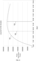
- FIG. 5 is a graph 300 illustrating a dosage distribution 302 for a long axial FOV system 120, in accordance with some embodiments.
- the graph 300 includes an x-axis showing dosage in kilobecquerels (kBq) per milliliter (ml) and a y-axis showing a noise equivalent count (NEC).
- a dosage distribution 302 includes an estimated noise equivalent count (NEC) curve for a predetermined long axial FOV scanner 120.
- a first position 304 on the dosage distribution 302 corresponds to a recommended dosage that does not account for prior patent imaging data and/or the long axial FOV scanner performance model.
- a second position 306 corresponds to an optimized dosage for the specific patient and the specific long axial FOV scanner 120. As illustrated in FIG.
- the optimized dosage 306 is less than the recommended dosage 304, resulting in a lower exposure of radiation to the patient during imaging.
- the disclosed method 200 allows a clinician to utilize prior scan data, such as prior short axial FOV PET scan data, to estimate a dose for subsequent long axial FOV scanning.
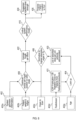
- FIG. 6 is a flowchart 400 illustrating a method of generating a patient dosage and position with respect to a long axial FOV system, in accordance with some embodiments.
- a set of prescan data 402 is received by a system, such as the computer system 30.
- the set of prescan data 402a-402e includes system geometric information 402a for the long axial FOV scanner 120, patient physical statistics 402b such as height and weight, a set of organs to be scanned 402c, a radiotracer identifier 402d, and patient age 402e.
- an absorbed dose per unit activity 420 is determined based on a patient age 402e and a data set correlating the radiotracer identifier 402d to dosage information, such as, for example, as provided in publicly available data 421 sets such as the ICRP Publication 128 "Radiation Dose to Patients from Radiopharmaceuticals: A Compendium of Current Information Related to Frequently Used Substances " and/or proprietary data sets.
- the absorbed dose per unity activity 420 may be determined, for example, by use of a look-up table, although it will be appreciated that any suitable method of identifying the absorbed dose per unity activity 420 may be used.
- the absorbed dose per unity activity 420 and the identification of the set of organs to be scanned 402c is used to normalize the absorbed dose per unity activity 420 to an absorption rate for the organ in the set of organs to be scanned 402c having the highest absorption percentage.
- the expected event activity (e.g., singles activity) is distributed per organ position for a predetermined (e.g., solid) angle based on the normalized absorbed dose per unity activity 420, the patient physical statistics 402b, and the system geometric information 402a.
- the distribution of the expected event activity generates an average single (event) per block 422.
- the disclosed methods allow a clinician to identify optimal bed positions and radiotracer dosage levels for producing optimal images.
- the optimal radiotracer dosage levels are generally lower dosage levels than those suggested for short axial FOV scanners.
- the disclosed methods adapt the dosage and bed position based on patient body types and age, improve images and reducing dosage, for example, in pediatric imaging.
- the optimized dosage levels allow a clinician to obtain only a needed dosage for a patient, reducing costs and inventory for radiotracers.
- a computer-implemented method includes receiving a set of prescan parameters, determining an average single per block for a long axial field-of-view (FOV) scanner based on the prescan parameters, and determining at least one scan parameter based on the average single per block for the long axial FOV scanner.
- FOV field-of-view
- the average single per block may be based on a distributed activity per organ position at a predetermined angle of the long axial FOV scanner.
- the distributed activity per organ may be determined based on an absorption rate normalized to a highest absorption organ rate for a set of target organs.
- the set of prescan parameters includes a patient height, a patient weight, and system geometric information for the long axial FOV scanner and the distributed activity per organ is based on a patient body mass index and the system geometric information.
- the prescan parameters may include a patient age and a radiotracer identifier and the average single per block may be determined based on an absorbed dose per unit activity administered for the patient age and the radiotracer identifier.
- the at least one scan parameter may include a dose strength for an identified radiotracer.
- the at least one scan parameter may include a patient bed position within a FOV of the long axial FOV scanner.
- a system in a second embodiment, includes a long axial FOV scanner and a computer.
- the computer is configured to receive a set of prescan parameters, determine an average single per block for the long axial field-of-view (FOV) scanner based on the prescan parameters, and determine at least one scan parameter based on the average single per block for the long axial FOV scanner.
- FOV field-of-view
- the set of prescan parameters may include a patient height, a patient weight, and system geometric information for the long axial FOV scanner and the distributed activity per organ may be based on a patient body mass index and the system geometric information.
- the prescan parameters may include a patient age and a radiotracer identifier and the average single per block may be determined based on an absorbed dose per unit activity administered for the patient age and the radiotracer identifier.
- the at least one scan parameter may include a dose strength for an identified radiotracer.
- a computer-implemented method for determining an optimal dose for a long axial FOV scanner based on data obtained using a short axial FOV scanner includes receiving scan data obtained using a short axial FOV scanner and patient data associated with the scan data.
Landscapes
- Life Sciences & Earth Sciences (AREA)
- Health & Medical Sciences (AREA)
- Engineering & Computer Science (AREA)
- Medical Informatics (AREA)
- Pathology (AREA)
- Heart & Thoracic Surgery (AREA)
- High Energy & Nuclear Physics (AREA)
- Physics & Mathematics (AREA)
- Nuclear Medicine, Radiotherapy & Molecular Imaging (AREA)
- Optics & Photonics (AREA)
- Veterinary Medicine (AREA)
- Radiology & Medical Imaging (AREA)
- Biomedical Technology (AREA)
- Biophysics (AREA)
- Molecular Biology (AREA)
- Surgery (AREA)
- Animal Behavior & Ethology (AREA)
- General Health & Medical Sciences (AREA)
- Public Health (AREA)
- Computer Vision & Pattern Recognition (AREA)
- Nuclear Medicine (AREA)
Claims (8)
- Procédé mis en œuvre par ordinateur, comprenant :la réception d'un ensemble de paramètres d'entrée (402a-402e) ;la détermination (408) d'un événement moyen par bloc (422) pour un scanner à long champ de vision (FOV) axial (120) ayant un champ de vision prédéterminé sur la base de l'ensemble de paramètres d'entrée (402a-402e), l'événement moyen par bloc (422) étant basé sur une activité répartie par organe positionné à l'intérieur du scanner à long FOV axial (120) ; etla détermination (410) d'au moins un paramètre de balayage (424, 426) sur la base de l'événement moyen par bloc (422) pour le scanner à long FOV axial (120).
- Procédé mis en œuvre par ordinateur selon la revendication 1, dans lequel l'activité répartie par organe est déterminée sur la base d'un taux d'absorption normalisé sur un taux d'absorption maximal d'organe pour un ensemble d'organes cibles (402c).
- Procédé mis en œuvre par ordinateur selon la revendication 1, dans lequel l'ensemble de paramètres d'entrée (402a-402e) comporte des données biométriques de patient et des informations géométriques de système (402a) pour le scanner à long FOV axial (120), et dans lequel l'activité répartie par organe est basée sur un indice de masse corporelle de patient et les informations géométriques de système (402a).
- Procédé mis en œuvre par ordinateur selon la revendication 1, dans lequel l'ensemble de paramètres d'entrée (402a-402e) comporte des données biométriques de patient et un identifiant de radiotraceur (402d), et dans lequel l'évènement moyen par bloc (422) est déterminé sur la base d'une dose absorbée par activité unitaire administrée (420) pour les données biométriques de patient et l'identifiant de radiotraceur (402d).
- Procédé mis en œuvre par ordinateur selon la revendication 1, dans lequel l'au moins un paramètre de balayage (424, 426) comporte une intensité de dose (424) pour un radiotraceur identifié.
- Procédé mis en œuvre par ordinateur selon la revendication 1, dans lequel l'au moins un paramètre de balayage (424, 426) comporte une position de patient (426) à l'intérieur du FOV prédéterminé du scanner à long FOV axial (120).
- Système, comprenant :un scanner à long FOV axial (120) ayant un FOV prédéterminé ; etun ordinateur conçu pour exécuter le procédé mis en œuvre par ordinateur selon l'une quelconque des revendications 1 à 6.
- Support non transitoire lisible par ordinateur stockant des instructions conçues pour conduire un système informatique à exécuter les étapes du procédé mis en œuvre par ordinateur selon l'une quelconque des revendications 1 à 6.
Applications Claiming Priority (1)
| Application Number | Priority Date | Filing Date | Title |
|---|---|---|---|
| PCT/US2019/053982 WO2021066808A1 (fr) | 2019-10-01 | 2019-10-01 | Optimisation de dose injectée basée sur un modèle pour une imagerie tep fov axiale longue |
Publications (3)
| Publication Number | Publication Date |
|---|---|
| EP4021304A1 EP4021304A1 (fr) | 2022-07-06 |
| EP4021304B1 true EP4021304B1 (fr) | 2025-03-19 |
| EP4021304C0 EP4021304C0 (fr) | 2025-03-19 |
Family
ID=68296728
Family Applications (1)
| Application Number | Title | Priority Date | Filing Date |
|---|---|---|---|
| EP19790998.9A Active EP4021304B1 (fr) | 2019-10-01 | 2019-10-01 | Optimisation de dose injectée basée sur un modèle pour une imagerie tep fov axiale longue |
Country Status (4)
| Country | Link |
|---|---|
| US (1) | US11974866B2 (fr) |
| EP (1) | EP4021304B1 (fr) |
| CN (1) | CN114423352A (fr) |
| WO (1) | WO2021066808A1 (fr) |
Families Citing this family (1)
| Publication number | Priority date | Publication date | Assignee | Title |
|---|---|---|---|---|
| EP4225147A1 (fr) * | 2020-11-13 | 2023-08-16 | Siemens Medical Solutions USA, Inc. | Système de manipulation de patient destiné à un système d'imagerie médicale |
Family Cites Families (16)
| Publication number | Priority date | Publication date | Assignee | Title |
|---|---|---|---|---|
| US7180074B1 (en) | 2001-06-27 | 2007-02-20 | Crosetto Dario B | Method and apparatus for whole-body, three-dimensional, dynamic PET/CT examination |
| US6963065B2 (en) * | 2003-04-18 | 2005-11-08 | Cti Pet Systems, Inc. | Normalization apparatus for panel detector PET scanners |
| US20040225214A1 (en) * | 2003-05-07 | 2004-11-11 | General Electric Company | Method of high-throughput quantitative pet for small animal imaging using a large-bore pet scanner for the assessment of pet tracer performance |
| US7964851B2 (en) * | 2005-06-10 | 2011-06-21 | Gsi Helmholtzzentrum Fuer Schwerionenforschung Gmbh | Method for the spectrometric photon dosimetry for X-ray and gamma radiation |
| US20140193336A1 (en) * | 2005-07-19 | 2014-07-10 | Biosensors International Group, Ltd. | Imaging protocols |
| EP3524159B1 (fr) * | 2010-12-08 | 2021-01-20 | Bayer Healthcare LLC | Génération d'un modèle approprié d'estimation de la dose de rayonnement reçue par un patient lors de procédures d'imagerie médicale |
| US8809792B2 (en) * | 2012-09-28 | 2014-08-19 | Kabushiki Kaisha Toshiba | Field-of-view-dependent coincidence window for positron emission tomography |
| EP2908729A1 (fr) * | 2012-10-19 | 2015-08-26 | Koninklijke Philips N.V. | Procédé de détermination de distribution de dose dans un corps |
| CN106725560B (zh) * | 2015-11-19 | 2021-01-12 | 上海联影医疗科技股份有限公司 | 光传感器的性能检测方法和医学成像设备 |
| CN108471996B (zh) * | 2015-12-17 | 2022-05-24 | 皇家飞利浦有限公司 | 一种用于估计由器官接收的辐射剂量的方法和成像设备 |
| DE102016207367A1 (de) * | 2016-04-29 | 2017-11-02 | Siemens Healthcare Gmbh | Festlegen von Scanparametern einer CT-Bildaufnahme mit Hilfe einer Außenbildaufnahme |
| US11660054B2 (en) * | 2016-11-22 | 2023-05-30 | Biogen Ma Inc. | Medical diagnostic and treatment systems and their methods of use |
| CN110167446A (zh) | 2016-12-21 | 2019-08-23 | 皇家飞利浦有限公司 | 用于改善成像性能的图像辅助的自动患者定位 |
| US9872664B1 (en) * | 2016-12-23 | 2018-01-23 | General Electric Company | Methods and systems for scatter correction in positron emission tomography |
| CN106725573B (zh) | 2017-01-16 | 2019-12-10 | 东软医疗系统股份有限公司 | 一种连续进床pet系统的计数丢失校正方法和装置 |
| CN109363709B (zh) * | 2018-12-19 | 2020-11-24 | 上海联影医疗科技有限公司 | Pet数据采集方法和pet系统 |
-
2019
- 2019-10-01 EP EP19790998.9A patent/EP4021304B1/fr active Active
- 2019-10-01 WO PCT/US2019/053982 patent/WO2021066808A1/fr not_active Ceased
- 2019-10-01 CN CN201980100955.5A patent/CN114423352A/zh active Pending
- 2019-10-01 US US17/596,837 patent/US11974866B2/en active Active
Also Published As
| Publication number | Publication date |
|---|---|
| WO2021066808A1 (fr) | 2021-04-08 |
| EP4021304C0 (fr) | 2025-03-19 |
| US20220296180A1 (en) | 2022-09-22 |
| CN114423352A (zh) | 2022-04-29 |
| EP4021304A1 (fr) | 2022-07-06 |
| US11974866B2 (en) | 2024-05-07 |
Similar Documents
| Publication | Publication Date | Title |
|---|---|---|
| US7507968B2 (en) | Systems and methods for correcting a positron emission tomography emission image | |
| US11222447B2 (en) | Inter-frame motion correction in whole-body direct parametric image reconstruction | |
| JP6479431B2 (ja) | 核医学診断装置及び結晶効率補正係数の計算方法 | |
| US9466132B2 (en) | Systems and methods for motion mitigation determinations | |
| US9684973B2 (en) | Systems and methods for selecting imaging data for principle components analysis | |
| US7518114B2 (en) | Method and system for imaging a patient | |
| US20240415480A1 (en) | Pet imaging using multiple organ specific short ct scans | |
| US20100308817A1 (en) | Adapting acquisition time in nuclear imaging | |
| US8058625B2 (en) | Limiting viewing angles in nuclear imaging | |
| US20190285469A1 (en) | Interaction characteristics from a plurality of pixels | |
| WO2016178115A1 (fr) | Génération de signaux respiratoires de substitution guidée par les données pour l'imagerie médicale | |
| JP2021189164A (ja) | ポジトロン放出断層撮影装置、方法及びプログラム | |
| US10534096B1 (en) | Photon scatter imaging | |
| US8064672B2 (en) | Patient scan time optimization for PET/SPECT imaging | |
| CN113729745B (zh) | 正电子发射断层摄影装置、方法以及存储介质 | |
| EP4021304B1 (fr) | Optimisation de dose injectée basée sur un modèle pour une imagerie tep fov axiale longue | |
| US20250265715A1 (en) | Adaptation of pet data acquisition parameters | |
| US20210174560A1 (en) | Scatter correction for long axial fov | |
| US12496020B2 (en) | High sensitivity continuous bed motion | |
| US20240161357A1 (en) | Material-Specific Attenuation Maps for Combined Imaging Systems Background | |
| US20200029928A1 (en) | Systems and methods for improved motion correction | |
| US20250228513A1 (en) | Nuclear medicine diagnosis apparatus and method | |
| JP4635848B2 (ja) | 核医学用のデータ処理方法および核医学診断装置 |
Legal Events
| Date | Code | Title | Description |
|---|---|---|---|
| STAA | Information on the status of an ep patent application or granted ep patent |
Free format text: STATUS: UNKNOWN |
|
| STAA | Information on the status of an ep patent application or granted ep patent |
Free format text: STATUS: THE INTERNATIONAL PUBLICATION HAS BEEN MADE |
|
| PUAI | Public reference made under article 153(3) epc to a published international application that has entered the european phase |
Free format text: ORIGINAL CODE: 0009012 |
|
| STAA | Information on the status of an ep patent application or granted ep patent |
Free format text: STATUS: REQUEST FOR EXAMINATION WAS MADE |
|
| 17P | Request for examination filed |
Effective date: 20220329 |
|
| AK | Designated contracting states |
Kind code of ref document: A1 Designated state(s): AL AT BE BG CH CY CZ DE DK EE ES FI FR GB GR HR HU IE IS IT LI LT LU LV MC MK MT NL NO PL PT RO RS SE SI SK SM TR |
|
| DAV | Request for validation of the european patent (deleted) | ||
| DAX | Request for extension of the european patent (deleted) | ||
| GRAP | Despatch of communication of intention to grant a patent |
Free format text: ORIGINAL CODE: EPIDOSNIGR1 |
|
| STAA | Information on the status of an ep patent application or granted ep patent |
Free format text: STATUS: GRANT OF PATENT IS INTENDED |
|
| RIC1 | Information provided on ipc code assigned before grant |
Ipc: A61B 6/42 20240101ALI20240920BHEP Ipc: A61B 6/40 20240101ALI20240920BHEP Ipc: A61B 6/00 20060101ALI20240920BHEP Ipc: A61B 6/03 20060101AFI20240920BHEP |
|
| INTG | Intention to grant announced |
Effective date: 20241014 |
|
| GRAS | Grant fee paid |
Free format text: ORIGINAL CODE: EPIDOSNIGR3 |
|
| GRAA | (expected) grant |
Free format text: ORIGINAL CODE: 0009210 |
|
| STAA | Information on the status of an ep patent application or granted ep patent |
Free format text: STATUS: THE PATENT HAS BEEN GRANTED |
|
| AK | Designated contracting states |
Kind code of ref document: B1 Designated state(s): AL AT BE BG CH CY CZ DE DK EE ES FI FR GB GR HR HU IE IS IT LI LT LU LV MC MK MT NL NO PL PT RO RS SE SI SK SM TR |
|
| REG | Reference to a national code |
Ref country code: GB Ref legal event code: FG4D |
|
| REG | Reference to a national code |
Ref country code: CH Ref legal event code: EP |
|
| REG | Reference to a national code |
Ref country code: DE Ref legal event code: R096 Ref document number: 602019067518 Country of ref document: DE |
|
| REG | Reference to a national code |
Ref country code: IE Ref legal event code: FG4D |
|
| U01 | Request for unitary effect filed |
Effective date: 20250319 |
|
| U07 | Unitary effect registered |
Designated state(s): AT BE BG DE DK EE FI FR IT LT LU LV MT NL PT RO SE SI Effective date: 20250325 |
|
| PG25 | Lapsed in a contracting state [announced via postgrant information from national office to epo] |
Ref country code: RS Free format text: LAPSE BECAUSE OF FAILURE TO SUBMIT A TRANSLATION OF THE DESCRIPTION OR TO PAY THE FEE WITHIN THE PRESCRIBED TIME-LIMIT Effective date: 20250619 |
|
| PG25 | Lapsed in a contracting state [announced via postgrant information from national office to epo] |
Ref country code: NO Free format text: LAPSE BECAUSE OF FAILURE TO SUBMIT A TRANSLATION OF THE DESCRIPTION OR TO PAY THE FEE WITHIN THE PRESCRIBED TIME-LIMIT Effective date: 20250619 |
|
| PG25 | Lapsed in a contracting state [announced via postgrant information from national office to epo] |
Ref country code: HR Free format text: LAPSE BECAUSE OF FAILURE TO SUBMIT A TRANSLATION OF THE DESCRIPTION OR TO PAY THE FEE WITHIN THE PRESCRIBED TIME-LIMIT Effective date: 20250319 |
|
| PG25 | Lapsed in a contracting state [announced via postgrant information from national office to epo] |
Ref country code: GR Free format text: LAPSE BECAUSE OF FAILURE TO SUBMIT A TRANSLATION OF THE DESCRIPTION OR TO PAY THE FEE WITHIN THE PRESCRIBED TIME-LIMIT Effective date: 20250620 |
|
| PG25 | Lapsed in a contracting state [announced via postgrant information from national office to epo] |
Ref country code: SM Free format text: LAPSE BECAUSE OF FAILURE TO SUBMIT A TRANSLATION OF THE DESCRIPTION OR TO PAY THE FEE WITHIN THE PRESCRIBED TIME-LIMIT Effective date: 20250319 |
|
| PG25 | Lapsed in a contracting state [announced via postgrant information from national office to epo] |
Ref country code: ES Free format text: LAPSE BECAUSE OF FAILURE TO SUBMIT A TRANSLATION OF THE DESCRIPTION OR TO PAY THE FEE WITHIN THE PRESCRIBED TIME-LIMIT Effective date: 20250319 |
|
| PG25 | Lapsed in a contracting state [announced via postgrant information from national office to epo] |
Ref country code: PL Free format text: LAPSE BECAUSE OF FAILURE TO SUBMIT A TRANSLATION OF THE DESCRIPTION OR TO PAY THE FEE WITHIN THE PRESCRIBED TIME-LIMIT Effective date: 20250319 |
|
| PG25 | Lapsed in a contracting state [announced via postgrant information from national office to epo] |
Ref country code: CZ Free format text: LAPSE BECAUSE OF FAILURE TO SUBMIT A TRANSLATION OF THE DESCRIPTION OR TO PAY THE FEE WITHIN THE PRESCRIBED TIME-LIMIT Effective date: 20250319 |
|
| PG25 | Lapsed in a contracting state [announced via postgrant information from national office to epo] |
Ref country code: SK Free format text: LAPSE BECAUSE OF FAILURE TO SUBMIT A TRANSLATION OF THE DESCRIPTION OR TO PAY THE FEE WITHIN THE PRESCRIBED TIME-LIMIT Effective date: 20250319 |
|
| PG25 | Lapsed in a contracting state [announced via postgrant information from national office to epo] |
Ref country code: IS Free format text: LAPSE BECAUSE OF FAILURE TO SUBMIT A TRANSLATION OF THE DESCRIPTION OR TO PAY THE FEE WITHIN THE PRESCRIBED TIME-LIMIT Effective date: 20250719 |
|
| U20 | Renewal fee for the european patent with unitary effect paid |
Year of fee payment: 7 Effective date: 20251020 |
|
| PGFP | Annual fee paid to national office [announced via postgrant information from national office to epo] |
Ref country code: GB Payment date: 20251111 Year of fee payment: 7 |
|
| PLBE | No opposition filed within time limit |
Free format text: ORIGINAL CODE: 0009261 |
|
| STAA | Information on the status of an ep patent application or granted ep patent |
Free format text: STATUS: NO OPPOSITION FILED WITHIN TIME LIMIT |
|
| REG | Reference to a national code |
Ref country code: CH Ref legal event code: L10 Free format text: ST27 STATUS EVENT CODE: U-0-0-L10-L00 (AS PROVIDED BY THE NATIONAL OFFICE) Effective date: 20260128 |
|
| 26N | No opposition filed |
Effective date: 20251222 |