EP4021759B1 - Siège de véhicule et système de siège arrière doté d'un agencement de ventilateur - Google Patents
Siège de véhicule et système de siège arrière doté d'un agencement de ventilateur Download PDFInfo
- Publication number
- EP4021759B1 EP4021759B1 EP20764328.9A EP20764328A EP4021759B1 EP 4021759 B1 EP4021759 B1 EP 4021759B1 EP 20764328 A EP20764328 A EP 20764328A EP 4021759 B1 EP4021759 B1 EP 4021759B1
- Authority
- EP
- European Patent Office
- Prior art keywords
- seat
- fan
- seat cushion
- vehicle
- air duct
- Prior art date
- Legal status (The legal status is an assumption and is not a legal conclusion. Google has not performed a legal analysis and makes no representation as to the accuracy of the status listed.)
- Active
Links
Images


Classifications
-
- B—PERFORMING OPERATIONS; TRANSPORTING
- B60—VEHICLES IN GENERAL
- B60N—SEATS SPECIALLY ADAPTED FOR VEHICLES; VEHICLE PASSENGER ACCOMMODATION NOT OTHERWISE PROVIDED FOR
- B60N2/00—Seats specially adapted for vehicles; Arrangement or mounting of seats in vehicles
- B60N2/56—Heating or ventilating devices
- B60N2/5607—Heating or ventilating devices characterised by convection
- B60N2/5621—Heating or ventilating devices characterised by convection by air
- B60N2/5635—Heating or ventilating devices characterised by convection by air coming from the passenger compartment
-
- B—PERFORMING OPERATIONS; TRANSPORTING
- B60—VEHICLES IN GENERAL
- B60N—SEATS SPECIALLY ADAPTED FOR VEHICLES; VEHICLE PASSENGER ACCOMMODATION NOT OTHERWISE PROVIDED FOR
- B60N2/00—Seats specially adapted for vehicles; Arrangement or mounting of seats in vehicles
- B60N2/56—Heating or ventilating devices
- B60N2/5607—Heating or ventilating devices characterised by convection
- B60N2/5621—Heating or ventilating devices characterised by convection by air
- B60N2/5657—Heating or ventilating devices characterised by convection by air blown towards the seat surface
Definitions
- the invention relates to a vehicle seat for a rear seat system of a motor vehicle, with a seat part which has a base pan and a seat cushion arranged on the base pan, wherein the base pan is designed to be placed on and fastened to a body wall of the motor vehicle, and with a fan device integrated into the seat part, which has at least one electrically operated fan and at least one air duct leading from an edge region of the seat part to the fan.
- the invention relates to a rear seat system for a motor vehicle, with a body wall arranged elevated in the rear seat area of the motor vehicle and at least substantially horizontally aligned, and with at least one vehicle seat arranged on the body wall.
- Ventilation devices for vehicle seats are increasingly found in all types of motor vehicles. They enable active seat ventilation, through which ambient air is sucked in and conveyed through the seat cushion and a seat cover.
- the seat cover has a large number of air outlet openings and the seat cushion is designed to allow air to flow through.
- the patent specification DE 196 28 698 C1 discloses such a vehicle seat.
- the air intake opening is arranged below the seat part, so that air is sucked in from the space below the seat part.
- the air flow undergoes a reversal of flow direction and the air is sucked in from a space that is more likely to be dusty and dirty.
- a generic vehicle seat which has a fan device.
- An air duct is formed on the underside of the floor pan, which faces the body wall when installed.
- the vehicle seat can be placed on a body wall and is therefore suitable for a rear seat system in which, for example, an individual seat frame is not required.
- the disclosure document DE 10 2011 121 331 A1 discloses a seat ventilation device for a vehicle seat, with an air supply channel which comprises a fan channel region and a supply channel region connected thereto, the latter opening into an outlet opening.
- the outlet opening is arranged on a narrow side of a cushion layer and concealed by a cover. Both the fan channel region and the supply channel region connected thereto run completely within the cushion layer.
- the invention is based on the object of creating an improved vehicle seat which ensures improved air flow for the fan device without requiring additional material or cost.
- the object underlying the invention is achieved by a vehicle seat with the features of claim 1.
- This has the advantage that, despite being designed for a rear seat system, it ensures advantageous air intake, which causes low flow losses and is nevertheless not easily visible to the user from the outside.
- the air duct is formed at least substantially between the seat cushion and the floor pan, that the floor pan has an edge section in the edge region that is arranged at a distance from the seat cushion in order to form an intake opening, and that the air duct opens into the intake opening at a distance from an outer edge of the seat cushion.
- the edge section of the floor pan is therefore at a distance from the seat cushion, so that an intake opening is formed between the seat cushion and the edge section, which serves to supply air for ventilation.
- the distance of the edge section from the seat cushion creates a distance in height (when installed as intended) so that the intake opening is below the seat cushion. Because the air duct opens into the intake opening at a distance from the outer edge of the seat cushion, the air duct is not visible from the outside, and the intake opening forms an extension of the air duct, which, however, as already described, is located below the seat cushion. Because the air duct merges into the intake opening, and this faces the edge section or the edge region of the vehicle seat, in particular the seat part, an air flow conveying direction is created that sucks in air from the area in front of the vehicle seat and not from below the vehicle seat.
- the vehicle seat also has a backrest associated with the seat part, which is fixed or pivotable, for example, to the seat part, at the end of the seat part facing away from the intake opening in the longitudinal direction. is stored.
- a backrest associated with the seat part, which is fixed or pivotable, for example, to the seat part, at the end of the seat part facing away from the intake opening in the longitudinal direction. is stored.
- the air duct and the intake opening are designed in such a way that an air flow from the intake opening to the fan passes without flow reversal. There is therefore no flow reversal in the flow path of the air flow from the intake opening to the fan, whereby flow losses are avoided and high air flow volumes are achieved.
- the edge section of the floor pan is aligned in such a way that a distance between the seat cushion and the floor pan increases towards the outer edge of the seat cushion.
- the edge section is thus inclined downwards when the vehicle seat is mounted, so that a free end is arranged lower than the end facing the air duct. This creates an intake funnel in the area of the intake opening, which allows for improved air intake and supply.
- the fan is arranged at a distance from the edge section in the air duct, so that the fan is arranged, for example, further in the rear area or at least at a distance from the outer edge of the seat cushion in order to achieve comfort advantages by the fan being located in an area that is better or more strongly protected by the seat cushion.
- the fan is arranged on the side of the air duct facing away from the floor pan.
- the fan is thus located above the air duct and sucks in the air from the intake opening and conveys it directly upwards into the seat cushion or through the seat cushion and an optional seat cover. This results in an advantageous, particularly space-saving arrangement of the fan in the seat part.
- the air channel has a channel wall supporting the air cushion, at least on the side of the air cushion.
- the channel wall ensures that the air channel is not narrowed or can collapse.
- the duct wall thus ensures the flow cross-section of the air duct at all times.
- the fan preferably has a housing that is connected to the duct wall. This ensures a safe and flow-optimized flow of the air stream from the air duct into the housing of the fan, and also allows for easy installation of the fan device.
- the air duct or the duct wall and the housing of the fan can be designed as a pre-assembly unit in order to then be arranged and/or attached together to the seat cushion and/or the floor pan.
- a wire frame in particular a spring wheel frame, is arranged in the seat cushion, which serves to provide suspension and thus increase the comfort of the seat part.
- the wire frame is preferably guided around the fan device so that the wire frame and the housing of the fan as well as the channel wall of the air channel do not meet. This ensures advantageous integration of the suspension into the seat cushion.
- the rear seat system according to the invention with the features of claim 9 is characterized by the inventive design of the vehicle seat. This results in the advantages already mentioned.
- the fan device is preferably assigned to a long side of the seat part.
- the fan device When viewed from above, the fan device is therefore located off-center and therefore in an area that is less heavily loaded by a user, so that optimal seating comfort is guaranteed.
- the intake opening is also located off-center, so that air is most likely sucked in from an area in which the user's legs are not expected to be in a normal sitting position.
- each long side of the seat part is assigned a correspondingly designed fan device, so that the air flow volume is doubled and improved ventilation for the user of the vehicle seat is guaranteed.
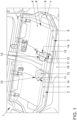
- FIG. 1 shows a simplified perspective view of a rear seat system 1 with two vehicle seats 2 and 3 arranged next to one another.
- the rear seat system 1 has a body wall 4, on which a seat part 5, 6 is arranged for each vehicle seat 2, 3.
- the seat parts 5, 6 each have a seat cover 7 (not shown here), a seat cushion 8 located beneath the seat cover, and a floor pan 9.
- the floor pan 9 rests at least partially on the body wall 4 and thus serves to hold and attach the vehicle seats 2, 3 to the body of the motor vehicle.
- the floor pan 9 also serves as a support for the seat cushion 8 and the seat cover 9.
- the seat parts 5, 6 have a common seat cushion 8, a common seat cover 7, and a common floor pan 9.
- the floor pan 9, the seat cover 7 and the seat cushion 8 thus extend over the entire width of the rear seat system 1.
- the seat parts 5, 6 are mirror images of each other and otherwise have at least essentially the same structure. The structure of both seat parts 5, 6 will now be described using the seat part 3.
- FIG 2 shows the rear seat system 1 in a perspective sectional view along the line AA from Figure 1 .
- the seat part 6 has a fan device 10 which is integrated into the seat part 6.
- the seat part 5 is assigned a correspondingly designed fan device 10, as in Figure 1 shown.
- the fan device 10 has a fan 11, which has a fan housing 12, in which a fan wheel (not shown here) can be driven by an electric motor.
- the housing 12 has a fan inlet opening 13 and a fan outlet opening 14, which is only Figure 1 shown, fan outlet opening 14.
- the fan inlet opening 13 is axially aligned with respect to the axis of rotation of the fan wheel, and the fan outlet opening 14 is at least substantially radial or tangential.
- the fan outlet opening 14 is located in the seat cushion 8, so that air conveyed by the fan 10 is conveyed into the seat cushion 8.
- the seat cushion 8 is designed to be permeable to air or has a plurality of air channels that lead from the fan outlet opening 14 to the seat cover 7, which is also permeable to air, in particular provided with a plurality of air outlet openings.
- the fan 11 is arranged at a distance from an outer edge 15 in the longitudinal extension of the seat part 6, which is formed by the seat cover 7.
- the outer edge 15 lies in In the direction of travel, the fan 11 is arranged at the front or at the front end of the seat part 6, so that the fan 11 is set back from the front outer edge of the seat part 6 in the seat part 6.
- the fan 11 when viewed from above the seat part 6, the fan 11 is not arranged in the middle, but on a long side, namely the long side of the seat part 6 facing the adjacent seat part 5.
- the fan 11 is therefore arranged in an area that is subjected to little stress when the vehicle seat 3 is in use.
- the fans 11 of both seat parts 5, 6 are arranged close to the middle of the rear seat system 1, so that they are located in an area in which a center tunnel 16 is led through the body of the motor vehicle.
- the fans are therefore located in an area in which the legs of the users of the vehicle seats 2, 3 are not usually located, so that advantageous air intake is ensured.
- the housing 12 of the fan 11 is further connected to a channel wall 17, on which the seat cushion 8 rests in some areas.
- the channel wall 17 is spaced apart from the base pan 9, so that an air channel 18 is formed between the base pan 9 and the channel wall 17, which leads to the fan inlet opening 13.
- a further channel wall 22 is arranged opposite the channel wall 17, with the channel wall 22 resting on the base pan 9, so that the air channel 18 is formed between the channel walls 17, 22.
- the channel walls 17, 22 are particularly preferably formed in one piece with one another or at least firmly connected to one another.
- FIG 3 shows a simplified sectional view of the vehicle seat 3 along the line AA from Figure 1 .
- the seat cushion 8 is also shown here, as is the seat cover 7.
- the fan 11 is arranged on the upper duct wall 17, so that the fan inlet opening 13 is formed in the duct wall 17 and the fan 11 is arranged above the air duct 18.
- the air duct 18 opens into an intake opening 19 which is formed between the floor pan 9 and the seat cushion 8.
- the intake opening 19 is formed in the area of the air duct 18 in that an edge section 20 of the floor pan 9 facing the outer edge 15 is arranged at a distance from the seat cushion 8 below the seat cushion 8.
- the edge section 20 of the floor pan 9 is inclined in such a way that the distance between the floor pan 9 and the seat cushion 8 in In the direction of the outer edge 15 of the seat cushion 8 or the seat part 6, this creates a funnel-shaped intake opening 19 when viewed in longitudinal section.
- the air duct 18 opens into the air intake opening 19 at a distance from the outer edge 15, so that the intake opening 19 extends the air duct 18 below the seat cushion 8.
- the advantageous design of the vehicle seat 3 ensures that the air is sucked in from the footwell area of the motor vehicle 1 in front of the vehicle seat 3 and is conveyed into the air cushion 8 without reversing the flow direction. This results in low flow losses and increases the efficiency of the fan device 10. Because the air duct 18 is formed between the floor pan 9 and the seat cushion 8, the air duct 18 is already manufactured together with the seat part 5 or 6, so that the seat part 5, 6 can also be placed on different or differently shaped body walls 4 of a rear seat system 1 without affecting the air guidance or air flow. Rather, it is ensured that the air duct 18 always has the desired contour and shape as well as the desired course, and that the advantageous intake opening 19 ensures efficient and safe intake of air for ventilation.
- a spring wire frame 21 is also arranged in the seat cushion 8, which extends through the seat cushion in order to increase the load-bearing capacity and rigidity of the seat cushion 8 and at the same time improve the seating comfort for passengers.
- the spring wire frame 21 is designed in such a way that it also protects the fan device 10, so that the operation of the fan device 10 is permanently guaranteed.
- At least one further fan device 10 is assigned to each seat part 5, 6, so that the achievable volume flow for ventilating a person sitting on the respective seat part 5, 6 is or can be doubled.
Landscapes
- Engineering & Computer Science (AREA)
- Aviation & Aerospace Engineering (AREA)
- Transportation (AREA)
- Mechanical Engineering (AREA)
- Chair Legs, Seat Parts, And Backrests (AREA)
Claims (10)
- Siège de véhicule (2, 3) pour une installation de sièges arrière (1) d'un véhicule automobile, comportant une partie de siège (5, 6) qui présente un bac de fond (9) et un rembourrage de siège (8) disposé sur le bac de fond (9), dans lequel le bac de fond (9) est réalisé pour être déposé et fixé sur une paroi de carrosserie (4) du véhicule automobile, et comportant un dispositif de ventilation (10) intégré dans la partie de siège (5, 6), lequel dispositif de ventilation présente au moins un ventilateur (11) pouvant être actionné électriquement et au moins un canal d'air (18) menant d'une zone de bord de la partie de siège (5, 6) au ventilateur (11), dans lequel le canal d'air (18) est réalisé au moins sensiblement entre le rembourrage de siège (8) et le bac de fond (9), le bac de fond (9) présente dans la zone de bord une section de bord (20) qui est disposée à distance du rembourrage de siège (8), en dessous du rembourrage de siège (8), afin de former un interstice entre le bac de fond (9) et le rembourrage de siège (8) sous forme d'ouverture d'aspiration (19), et le canal d'air (18) débouche dans l'ouverture d'aspiration (19) à distance d'un bord extérieur (15) du rembourrage de siège (8), de sorte que l'ouverture d'aspiration (19) prolonge le canal d'air (18) en dessous du rembourrage de siège (8).
- Siège de véhicule selon la revendication 1, caractérisé en ce que la section de bord (20) du bac de fond (9) est orientée de telle sorte qu'une distance entre le rembourrage de siège (8) et le bac de fond (9) augmente en direction du bord extérieur (15) du rembourrage de siège (8).
- Siège de véhicule selon l'une des revendications précédentes, caractérisé en ce que le ventilateur (11) est disposé à distance de la section de bord (20) dans le canal d'air (18).
- Siège de véhicule selon l'une des revendications précédentes, caractérisé en ce que le canal d'air (18) et l'ouverture d'aspiration (19) sont réalisés de telle sorte qu'un flux d'air passe de l'ouverture d'aspiration (19) au ventilateur (11) sans inversion de flux.
- Siège de véhicule selon l'une des revendications précédentes, caractérisé en ce que le ventilateur (11) est disposé sur le côté du canal d'air (18) opposé au bac de fond (9).
- Siège de véhicule selon l'une des revendications précédentes, caractérisé en ce que le canal d'air (18) présente, au moins côté rembourrage de siège (8), une paroi de canal (17) soutenant le rembourrage de siège (8).
- Siège de véhicule selon l'une des revendications précédentes, caractérisé en ce que le ventilateur (11) présente un boîtier (12) qui est relié à la paroi de canal (17).
- Siège de véhicule selon l'une des revendications précédentes, caractérisé en ce qu'un cadre de fils, en particulier un cadre de fils de suspension élastiques (21), est disposé dans le rembourrage de siège (8).
- Installation de siège arrière (1) pour un véhicule automobile, comportant une paroi de carrosserie (4) disposée en hauteur dans la zone de siège arrière et orientée au moins sensiblement horizontalement, et comportant au moins un siège de véhicule (2, 3) disposé sur la paroi de carrosserie (4), caractérisée en ce que le siège de véhicule (2, 3) est réalisé selon l'une des revendications 1 à 8.
- Installation de siège arrière selon la revendication 9, caractérisée en ce que le dispositif de ventilation (10) est associé à un côté longitudinal de la partie de siège (5, 6).
Applications Claiming Priority (2)
| Application Number | Priority Date | Filing Date | Title |
|---|---|---|---|
| DE102019212992.7A DE102019212992A1 (de) | 2019-08-29 | 2019-08-29 | Fahrzeugsitz und Hintersitzanlage |
| PCT/EP2020/073696 WO2021037825A1 (fr) | 2019-08-29 | 2020-08-25 | Siège de véhicule et système de siège arrière doté d'un agencement de ventilateur |
Publications (2)
| Publication Number | Publication Date |
|---|---|
| EP4021759A1 EP4021759A1 (fr) | 2022-07-06 |
| EP4021759B1 true EP4021759B1 (fr) | 2025-01-22 |
Family
ID=72291008
Family Applications (1)
| Application Number | Title | Priority Date | Filing Date |
|---|---|---|---|
| EP20764328.9A Active EP4021759B1 (fr) | 2019-08-29 | 2020-08-25 | Siège de véhicule et système de siège arrière doté d'un agencement de ventilateur |
Country Status (4)
| Country | Link |
|---|---|
| EP (1) | EP4021759B1 (fr) |
| CN (1) | CN114269600A (fr) |
| DE (1) | DE102019212992A1 (fr) |
| WO (1) | WO2021037825A1 (fr) |
Citations (1)
| Publication number | Priority date | Publication date | Assignee | Title |
|---|---|---|---|---|
| US20200130548A1 (en) * | 2017-03-24 | 2020-04-30 | Ts Tech Co., Ltd. | Vehicle seat |
Family Cites Families (11)
| Publication number | Priority date | Publication date | Assignee | Title |
|---|---|---|---|---|
| DE19628698C1 (de) * | 1996-07-17 | 1997-10-09 | Daimler Benz Ag | Fahrzeugsitz |
| DE10261268B4 (de) * | 2002-04-09 | 2006-09-14 | Gerhard Pfeil | Belüftetes Liege- oder Sitzmöbel |
| DE102011122124C5 (de) * | 2011-01-06 | 2020-04-09 | I.G. Bauerhin Gmbh | Fahrzeugsitz |
| DE102011121331A1 (de) * | 2011-12-16 | 2012-06-21 | Daimler Ag | Polster für einen Fahrzeugsitz |
| DE102012006074A1 (de) * | 2012-03-24 | 2012-11-08 | Daimler Ag | Kraftfahrzeugsitz |
| DE202012010708U1 (de) * | 2012-11-09 | 2012-11-28 | I.G. Bauerhin Gmbh | Baugruppe für die Klimatisierung eines Fahrzeugsitzes |
| JP6555253B2 (ja) * | 2014-04-11 | 2019-08-07 | テイ・エス テック株式会社 | 乗物用シート |
| DE102015213299A1 (de) * | 2014-08-28 | 2016-03-17 | Mahle International Gmbh | Personenkraftwagen mit belüftetem Fondfußraum |
| EP3006262B1 (fr) * | 2014-10-07 | 2016-11-23 | C.R.F. Società Consortile per Azioni | Siège de véhicule à moteur pourvu d'un système permettant de fournir de l'air conditionné |
| DE102015210624A1 (de) * | 2015-06-10 | 2016-12-15 | Bombardier Transportation Gmbh | Schienenfahrzeug mit Klimatisierung über Sitze |
| US10780799B2 (en) * | 2016-09-05 | 2020-09-22 | Adient Luxembourg Holding S.À R.L. | Vehicle seat and vehicle |
-
2019
- 2019-08-29 DE DE102019212992.7A patent/DE102019212992A1/de not_active Withdrawn
-
2020
- 2020-08-25 WO PCT/EP2020/073696 patent/WO2021037825A1/fr not_active Ceased
- 2020-08-25 EP EP20764328.9A patent/EP4021759B1/fr active Active
- 2020-08-25 CN CN202080060855.7A patent/CN114269600A/zh active Pending
Patent Citations (1)
| Publication number | Priority date | Publication date | Assignee | Title |
|---|---|---|---|---|
| US20200130548A1 (en) * | 2017-03-24 | 2020-04-30 | Ts Tech Co., Ltd. | Vehicle seat |
Also Published As
| Publication number | Publication date |
|---|---|
| EP4021759A1 (fr) | 2022-07-06 |
| WO2021037825A1 (fr) | 2021-03-04 |
| CN114269600A (zh) | 2022-04-01 |
| DE102019212992A1 (de) | 2021-03-04 |
Similar Documents
| Publication | Publication Date | Title |
|---|---|---|
| DE10243315B4 (de) | Polster für einen Fahrzeugsitz | |
| DE10259621B4 (de) | Fahrzeugsitz und zugehörige Klimatisierungseinrichtung | |
| EP1323574A2 (fr) | Siège de véhicule | |
| DE102012006074A1 (de) | Kraftfahrzeugsitz | |
| DE19745521A1 (de) | Polster für einen Fahrzeugsitz | |
| DE10163050A1 (de) | Kopfstütze für einen Kraftfahrzeugsitz | |
| WO2014072037A1 (fr) | Module de climatisation d'un siège de véhicule | |
| DE102011122124B4 (de) | Fahrzeugsitz | |
| DE102018222477A1 (de) | Kindersitzanordnung | |
| DE102009052683A1 (de) | Fahrzeugsitz mit einer Luftversorgungseinrichtung | |
| EP3873774B1 (fr) | Siège de véhicule pour un véhicule automobile | |
| WO2007090526A1 (fr) | Rembourrage pour siège de véhicule | |
| EP4021759B1 (fr) | Siège de véhicule et système de siège arrière doté d'un agencement de ventilateur | |
| DE4126518C2 (de) | Fahrzeugsitz | |
| DE19941715C1 (de) | Polster für einen Fahrzeugsitz | |
| DE102005003849B3 (de) | Fahrzeugsitz mit Belüftungsvorrichtung | |
| DE10059358A1 (de) | Fahrzeugsitz mit Lüftung | |
| EP3456582A1 (fr) | Siège climatisé | |
| DE102005015238B4 (de) | Funktionssystem | |
| DE19906987B4 (de) | Rahmen für die Rückenlehne eines Fahrzeugsitzes | |
| EP2258584B1 (fr) | Dossier pour un siège de véhicule | |
| DE102012025365B4 (de) | Sitz, insbesondere Fahrzeugsitz | |
| DE102008047546A1 (de) | Kraftfahrzeug | |
| DE102019220267B4 (de) | Fahrzeugsitz für ein Kraftfahrzeug | |
| DE102018003186A1 (de) | Fahrzeugsitz |
Legal Events
| Date | Code | Title | Description |
|---|---|---|---|
| STAA | Information on the status of an ep patent application or granted ep patent |
Free format text: STATUS: UNKNOWN |
|
| STAA | Information on the status of an ep patent application or granted ep patent |
Free format text: STATUS: THE INTERNATIONAL PUBLICATION HAS BEEN MADE |
|
| PUAI | Public reference made under article 153(3) epc to a published international application that has entered the european phase |
Free format text: ORIGINAL CODE: 0009012 |
|
| STAA | Information on the status of an ep patent application or granted ep patent |
Free format text: STATUS: REQUEST FOR EXAMINATION WAS MADE |
|
| 17P | Request for examination filed |
Effective date: 20220329 |
|
| AK | Designated contracting states |
Kind code of ref document: A1 Designated state(s): AL AT BE BG CH CY CZ DE DK EE ES FI FR GB GR HR HU IE IS IT LI LT LU LV MC MK MT NL NO PL PT RO RS SE SI SK SM TR |
|
| DAV | Request for validation of the european patent (deleted) | ||
| DAX | Request for extension of the european patent (deleted) | ||
| GRAP | Despatch of communication of intention to grant a patent |
Free format text: ORIGINAL CODE: EPIDOSNIGR1 |
|
| STAA | Information on the status of an ep patent application or granted ep patent |
Free format text: STATUS: GRANT OF PATENT IS INTENDED |
|
| INTG | Intention to grant announced |
Effective date: 20241010 |
|
| GRAS | Grant fee paid |
Free format text: ORIGINAL CODE: EPIDOSNIGR3 |
|
| GRAA | (expected) grant |
Free format text: ORIGINAL CODE: 0009210 |
|
| STAA | Information on the status of an ep patent application or granted ep patent |
Free format text: STATUS: THE PATENT HAS BEEN GRANTED |
|
| AK | Designated contracting states |
Kind code of ref document: B1 Designated state(s): AL AT BE BG CH CY CZ DE DK EE ES FI FR GB GR HR HU IE IS IT LI LT LU LV MC MK MT NL NO PL PT RO RS SE SI SK SM TR |
|
| REG | Reference to a national code |
Ref country code: GB Ref legal event code: FG4D Free format text: NOT ENGLISH |
|
| REG | Reference to a national code |
Ref country code: CH Ref legal event code: EP |
|
| REG | Reference to a national code |
Ref country code: IE Ref legal event code: FG4D Free format text: LANGUAGE OF EP DOCUMENT: GERMAN |
|
| REG | Reference to a national code |
Ref country code: DE Ref legal event code: R096 Ref document number: 502020010281 Country of ref document: DE |
|
| P01 | Opt-out of the competence of the unified patent court (upc) registered |
Free format text: CASE NUMBER: APP_10661/2025 Effective date: 20250304 |
|
| REG | Reference to a national code |
Ref country code: NL Ref legal event code: MP Effective date: 20250122 |
|
| PG25 | Lapsed in a contracting state [announced via postgrant information from national office to epo] |
Ref country code: NL Free format text: LAPSE BECAUSE OF FAILURE TO SUBMIT A TRANSLATION OF THE DESCRIPTION OR TO PAY THE FEE WITHIN THE PRESCRIBED TIME-LIMIT Effective date: 20250122 |
|
| PG25 | Lapsed in a contracting state [announced via postgrant information from national office to epo] |
Ref country code: RS Free format text: LAPSE BECAUSE OF FAILURE TO SUBMIT A TRANSLATION OF THE DESCRIPTION OR TO PAY THE FEE WITHIN THE PRESCRIBED TIME-LIMIT Effective date: 20250422 |
|
| PG25 | Lapsed in a contracting state [announced via postgrant information from national office to epo] |
Ref country code: FI Free format text: LAPSE BECAUSE OF FAILURE TO SUBMIT A TRANSLATION OF THE DESCRIPTION OR TO PAY THE FEE WITHIN THE PRESCRIBED TIME-LIMIT Effective date: 20250122 |
|
| PG25 | Lapsed in a contracting state [announced via postgrant information from national office to epo] |
Ref country code: PL Free format text: LAPSE BECAUSE OF FAILURE TO SUBMIT A TRANSLATION OF THE DESCRIPTION OR TO PAY THE FEE WITHIN THE PRESCRIBED TIME-LIMIT Effective date: 20250122 |
|
| PG25 | Lapsed in a contracting state [announced via postgrant information from national office to epo] |
Ref country code: ES Free format text: LAPSE BECAUSE OF FAILURE TO SUBMIT A TRANSLATION OF THE DESCRIPTION OR TO PAY THE FEE WITHIN THE PRESCRIBED TIME-LIMIT Effective date: 20250122 |
|
| REG | Reference to a national code |
Ref country code: LT Ref legal event code: MG9D |
|
| PG25 | Lapsed in a contracting state [announced via postgrant information from national office to epo] |
Ref country code: NO Free format text: LAPSE BECAUSE OF FAILURE TO SUBMIT A TRANSLATION OF THE DESCRIPTION OR TO PAY THE FEE WITHIN THE PRESCRIBED TIME-LIMIT Effective date: 20250422 Ref country code: IS Free format text: LAPSE BECAUSE OF FAILURE TO SUBMIT A TRANSLATION OF THE DESCRIPTION OR TO PAY THE FEE WITHIN THE PRESCRIBED TIME-LIMIT Effective date: 20250522 |
|
| PG25 | Lapsed in a contracting state [announced via postgrant information from national office to epo] |
Ref country code: HR Free format text: LAPSE BECAUSE OF FAILURE TO SUBMIT A TRANSLATION OF THE DESCRIPTION OR TO PAY THE FEE WITHIN THE PRESCRIBED TIME-LIMIT Effective date: 20250122 |
|
| PG25 | Lapsed in a contracting state [announced via postgrant information from national office to epo] |
Ref country code: LV Free format text: LAPSE BECAUSE OF FAILURE TO SUBMIT A TRANSLATION OF THE DESCRIPTION OR TO PAY THE FEE WITHIN THE PRESCRIBED TIME-LIMIT Effective date: 20250122 Ref country code: PT Free format text: LAPSE BECAUSE OF FAILURE TO SUBMIT A TRANSLATION OF THE DESCRIPTION OR TO PAY THE FEE WITHIN THE PRESCRIBED TIME-LIMIT Effective date: 20250522 |
|
| PG25 | Lapsed in a contracting state [announced via postgrant information from national office to epo] |
Ref country code: BG Free format text: LAPSE BECAUSE OF FAILURE TO SUBMIT A TRANSLATION OF THE DESCRIPTION OR TO PAY THE FEE WITHIN THE PRESCRIBED TIME-LIMIT Effective date: 20250122 Ref country code: GR Free format text: LAPSE BECAUSE OF FAILURE TO SUBMIT A TRANSLATION OF THE DESCRIPTION OR TO PAY THE FEE WITHIN THE PRESCRIBED TIME-LIMIT Effective date: 20250423 |
|
| PG25 | Lapsed in a contracting state [announced via postgrant information from national office to epo] |
Ref country code: SE Free format text: LAPSE BECAUSE OF FAILURE TO SUBMIT A TRANSLATION OF THE DESCRIPTION OR TO PAY THE FEE WITHIN THE PRESCRIBED TIME-LIMIT Effective date: 20250122 |
|
| PG25 | Lapsed in a contracting state [announced via postgrant information from national office to epo] |
Ref country code: SM Free format text: LAPSE BECAUSE OF FAILURE TO SUBMIT A TRANSLATION OF THE DESCRIPTION OR TO PAY THE FEE WITHIN THE PRESCRIBED TIME-LIMIT Effective date: 20250122 |
|
| PG25 | Lapsed in a contracting state [announced via postgrant information from national office to epo] |
Ref country code: DK Free format text: LAPSE BECAUSE OF FAILURE TO SUBMIT A TRANSLATION OF THE DESCRIPTION OR TO PAY THE FEE WITHIN THE PRESCRIBED TIME-LIMIT Effective date: 20250122 |
|
| PGFP | Annual fee paid to national office [announced via postgrant information from national office to epo] |
Ref country code: DE Payment date: 20250831 Year of fee payment: 6 |
|
| PG25 | Lapsed in a contracting state [announced via postgrant information from national office to epo] |
Ref country code: IT Free format text: LAPSE BECAUSE OF FAILURE TO SUBMIT A TRANSLATION OF THE DESCRIPTION OR TO PAY THE FEE WITHIN THE PRESCRIBED TIME-LIMIT Effective date: 20250122 |
|
| PGFP | Annual fee paid to national office [announced via postgrant information from national office to epo] |
Ref country code: GB Payment date: 20250826 Year of fee payment: 6 |
|
| PGFP | Annual fee paid to national office [announced via postgrant information from national office to epo] |
Ref country code: FR Payment date: 20250825 Year of fee payment: 6 |
|
| PG25 | Lapsed in a contracting state [announced via postgrant information from national office to epo] |
Ref country code: EE Free format text: LAPSE BECAUSE OF FAILURE TO SUBMIT A TRANSLATION OF THE DESCRIPTION OR TO PAY THE FEE WITHIN THE PRESCRIBED TIME-LIMIT Effective date: 20250122 Ref country code: CZ Free format text: LAPSE BECAUSE OF FAILURE TO SUBMIT A TRANSLATION OF THE DESCRIPTION OR TO PAY THE FEE WITHIN THE PRESCRIBED TIME-LIMIT Effective date: 20250122 |
|
| REG | Reference to a national code |
Ref country code: DE Ref legal event code: R097 Ref document number: 502020010281 Country of ref document: DE |
|
| PG25 | Lapsed in a contracting state [announced via postgrant information from national office to epo] |
Ref country code: RO Free format text: LAPSE BECAUSE OF FAILURE TO SUBMIT A TRANSLATION OF THE DESCRIPTION OR TO PAY THE FEE WITHIN THE PRESCRIBED TIME-LIMIT Effective date: 20250122 |
|
| PG25 | Lapsed in a contracting state [announced via postgrant information from national office to epo] |
Ref country code: SK Free format text: LAPSE BECAUSE OF FAILURE TO SUBMIT A TRANSLATION OF THE DESCRIPTION OR TO PAY THE FEE WITHIN THE PRESCRIBED TIME-LIMIT Effective date: 20250122 |
|
| PLBE | No opposition filed within time limit |
Free format text: ORIGINAL CODE: 0009261 |
|
| STAA | Information on the status of an ep patent application or granted ep patent |
Free format text: STATUS: NO OPPOSITION FILED WITHIN TIME LIMIT |
|
| REG | Reference to a national code |
Ref country code: CH Ref legal event code: L10 Free format text: ST27 STATUS EVENT CODE: U-0-0-L10-L00 (AS PROVIDED BY THE NATIONAL OFFICE) Effective date: 20251203 |
|
| 26N | No opposition filed |
Effective date: 20251023 |
|
| REG | Reference to a national code |
Ref country code: CH Ref legal event code: H13 Free format text: ST27 STATUS EVENT CODE: U-0-0-H10-H13 (AS PROVIDED BY THE NATIONAL OFFICE) Effective date: 20260324 |
|
| PG25 | Lapsed in a contracting state [announced via postgrant information from national office to epo] |
Ref country code: MC Free format text: LAPSE BECAUSE OF FAILURE TO SUBMIT A TRANSLATION OF THE DESCRIPTION OR TO PAY THE FEE WITHIN THE PRESCRIBED TIME-LIMIT Effective date: 20250122 |
|
| PG25 | Lapsed in a contracting state [announced via postgrant information from national office to epo] |
Ref country code: LU Free format text: LAPSE BECAUSE OF NON-PAYMENT OF DUE FEES Effective date: 20250825 |