EP4021776B1 - Dispositif et procédé pour surveiller un processus de sablage pour une installation de sablage pour un véhicule sur rails, dispositif de sablage, véhicule sur rails et ensemble voie - Google Patents
Dispositif et procédé pour surveiller un processus de sablage pour une installation de sablage pour un véhicule sur rails, dispositif de sablage, véhicule sur rails et ensemble voie Download PDFInfo
- Publication number
- EP4021776B1 EP4021776B1 EP20765229.8A EP20765229A EP4021776B1 EP 4021776 B1 EP4021776 B1 EP 4021776B1 EP 20765229 A EP20765229 A EP 20765229A EP 4021776 B1 EP4021776 B1 EP 4021776B1
- Authority
- EP
- European Patent Office
- Prior art keywords
- grit
- sanding
- signal
- grinding
- rail
- Prior art date
- Legal status (The legal status is an assumption and is not a legal conclusion. Google has not performed a legal analysis and makes no representation as to the accuracy of the status listed.)
- Active
Links
Images


Classifications
-
- B—PERFORMING OPERATIONS; TRANSPORTING
- B61—RAILWAYS
- B61C—LOCOMOTIVES; MOTOR RAILCARS
- B61C15/00—Maintaining or augmenting the starting or braking power by auxiliary devices and measures; Preventing wheel slippage; Controlling distribution of tractive effort between driving wheels
- B61C15/08—Preventing wheel slippage
- B61C15/10—Preventing wheel slippage by depositing sand or like friction increasing materials
- B61C15/107—Preventing wheel slippage by depositing sand or like friction increasing materials with electrically or electromagnetically controlled sanding equipment
Definitions
- the present approach relates to a device and a method for monitoring a sanding process for a sanding system for a rail vehicle and to a sanding device, a rail vehicle and a track device.
- the WO 2014/108316 A1 discloses a method and apparatus for analyzing a spreading agent and for controlling application of a spreading agent to a rail for a rail vehicle.
- the object of the present approach is to create an improved sanding device, an improved rail vehicle, an improved track device, and an improved method for monitoring a sanding process.
- a device for monitoring a sanding process for a sanding system for a rail vehicle has an evaluation device which is designed to read in a grinding signal which represents a grinding process sensed by a sensor device, which involves grinding at least one grain of grit in a wheel rail gap between a rail and a Wheel of the rail vehicle represents.
- the device is further designed to use the grinding signal to determine a grit quantity signal which indicates a grit quantity of ground grit grains during the sanding process.
- grit can be applied from the rail vehicle's sanding system.
- Gritting agents can be based on both naturally occurring (degraded) media and artificially produced substances.
- a typical grit is sand, which can also be used here as a synonym for grit.
- the grinding signal can indicate a physical quantity sensed by the sensor device during the sanding process, for example a sensed acceleration, a sensed sound, such as a noise, or a vibration.
- a characteristic of the grinding signal can depend on whether and, if so, how much of the applied spreading agent is ground. Thus, by appropriately evaluating the characteristics of the grinding signal, conclusions can be drawn about the amount of grit grains ground during the sanding process.
- the grinding signal can be evaluated both in the time domain and in the frequency domain.
- a device for monitoring a sanding process advantageously makes it possible to detect the amount of grit on ground grit grains, whereby a function or malfunction of the sanding system can be checked.
- the grit quantity signal can provide information about whether a large amount of grit landed on the rail during the sanding process, or whether an undesirable amount of grit landed next to the rail.
- a sand pipe or another component of the sanding system can subsequently be checked or readjusted accordingly in order to ensure an ideal sanding process in the future to ensure faster and additionally or alternatively stronger braking of the rail vehicle.
- the device can also have the sensor device, which is designed to sense the grinding process and to provide the grinding signal representing the sensed grinding process. If the evaluation device and the sensor device are arranged separately from one another, a wireless or wired communication interface can be provided between the evaluation device and the sensor device.
- the evaluation device and the sensor device can be arranged together on the rail vehicle or together on a track device or divided between the rail vehicle and the track device.
- the sensor device is designed to detect an acceleration of an element of the rail vehicle or a rail element of a track device and additionally or alternatively a sound wave and to provide an acceleration signal representing the acceleration.
- the element of the rail vehicle can be a wheel or a wheel axle of the rail vehicle.
- the sound wave can be a structure-borne sound wave or an airborne sound wave.
- the sensor device can be designed to detect an acoustic signal.
- An acoustic evaluation is advantageous.
- the sensor device can, for example, comprise an acceleration sensor and additionally or alternatively at least one membrane or a microphone.
- the microphone can be arranged on the sand hose, for example on the sand pipe heater.
- the acceleration signal and in particular the acceleration signal provided during the sanding process can thus be used by the device as the grinding signal.
- Such a sensor device creates a simple method of sensing the grinding process.
- the device can further have a transmitting device which is designed to send the spreading agent amount signal to a vehicle control of the rail vehicle. That's how it can be done Spreading agent quantity signal can be further processed by an existing vehicle control system of the rail vehicle.
- the evaluation device can be designed to evaluate the amplitude and additionally or alternatively the frequency of the grinding signal in order to determine the scattering agent amount signal.
- the amplitude of the grinding signal can advantageously provide information as to whether there is any grit on the rail when the rail vehicle travels.
- the frequency can provide an overview of when and how much grit is ground during the sanding process.
- the evaluation device can be designed to compare the grinding signal with a specified amplitude limit in order to recognize the grinding process. If the amplitude of the grinding signal exceeds the amplitude limit value, the presence of scattering agent can be concluded. Additionally or alternatively, the evaluation device can be designed to determine and evaluate a frequency spectrum of the grinding signal in order to determine the ground amount of scattering agent. For example, the amount of scattering agent ground per unit of time can be deduced from a distribution or an average of the frequencies included in the grinding signal. This creates a very quick way to monitor the sanding process.
- the evaluation device can be designed to evaluate the frequency spectrum in order to determine the amount of ground grit within a certain period of time or the entire sanding process. In this way, the sanding process can be monitored periodically or continuously, for example.
- the device has a comparison device which is designed to output a warning signal using the spreading agent amount signal and a target spreading agent quantity signal, which represents an expected spreading agent amount of ground spreading agent grains, if the Amount of ground grit grains differs from the desired amount of ground grit grains.
- the comparison device can be designed to output a confirmation signal when the amount of ground grit grains corresponds to the desired amount of ground grit grains.
- the comparison device can be implemented in the evaluation device or the vehicle control.
- the target spreading agent quantity signal can be a signal provided or read in by a sanding request device of the sanding system.
- the comparison device can be designed to compare the amount of ground grit grains with the expected amount of ground grains and to output either the warning signal or the confirmation signal depending on a comparison result.
- the confirmation signal can be understood as an all-clear signal that indicates a correct amount of ground grit grains. This creates a distinction for recognizing whether the amount of ground grit grains is correct or not.
- the warning signal can be designed to display information to a driver of the rail vehicle about an incorrect amount of ground grit. Additionally or alternatively, the warning signal can be designed to indicate a difference between the amount of grit dispensed and the ground grit grains and additionally or alternatively to change an orientation of a sand pipe of the sanding system. For example, the warning signal can be suitable for activating a visual or acoustic display device.
- the sensor device and the evaluation device can be formed as one component or can be formed as at least two separate components.
- the sensor device and the evaluation device can, for example, be accommodated in a common housing or the evaluation device can be incorporated into the sensor device be arranged integrated.
- the sensor device and the evaluation device can be accommodated in separate housings, for example.
- the complete device can be arranged, for example, near the wheel rail gap, for example on the wheel or axle bearing or on a wheel bearing, for example in a single-wheel chassis, of the rail vehicle or on a rail element of a track device, in order to ideally sense and evaluate the grinding of grit grains to be able to.
- at least the sensor device can be arranged near the wheel rail gap and the evaluation by the evaluation device can take place, for example, in another area of the rail vehicle, which is protected from environmental influences, for example.
- a sanding device for a rail vehicle has a sanding system and a device which is designed in one of the variants described above.
- Such a sanding device can advantageously enable the rail vehicle to be sanded and, thanks to the device, monitor its own sanding function.
- a rail vehicle with such a sanding device is also presented.
- This rail vehicle can advantageously be sanded effectively, with the sanding process being optimally monitored thanks to the device.
- At least the sensor device of the device can be arranged on or in an axle bearing, a wheel axle, a wheel, a bogie and additionally or alternatively a substructure of the rail vehicle.
- the entire device can also be arranged on or in the axle bearing, the wheel axle, the wheel, the bogie or the substructure of the rail vehicle. The positions mentioned are close to the wheel rail gap and enable ideal sensing of the grinding of grit grains.
- a track device with a rail element has one of the devices described above, with at least the sensor device being arranged on or in the rail element.
- the entire device can also be arranged on or in the rail element.
- the rail element can be a component of the Be a rail or a rail sleeper.
- Such a track device is suitable, for example, for use in connection with a test track system for testing the sanding process outside of the normal driving operation of the rail vehicle.
- the device can be designed to output a sanding signal to the sanding system of the rail vehicle in response to an activation signal that represents an approach of the rail vehicle to the sensor device in order to start the sanding process.
- the activation signal can be output or provided by a detection device, which is arranged, for example, on or in the rail element.
- the detection device can also be part of the device.
- Such a track device can advantageously be used to test the sanding process of the sanding system before the sanding system is to be used in normal driving operations for the rail vehicle.
- a method for monitoring a sanding process for a sanding system for a rail vehicle has a reading step and a determining step.
- a grinding signal is read in, which represents a grinding process sensed by a sensor device, which represents grinding of at least one grain of grit in a wheel rail gap between a rail and a wheel of the rail vehicle.
- a spreading agent amount signal is determined using the grinding signal, which indicates a spreading agent amount of ground spreading agent grains during the sanding process.
- This method can be implemented, for example, in software or hardware or in a mixed form of software and hardware, for example in the device described above.
- Fig. 1 shows a schematic side view of a rail vehicle 100 with a sanding device 105 with a sanding system 110 and a device 115 for monitoring a sanding process of the sanding system 110 according to an exemplary embodiment.
- the sanding device 105 is included on the rail vehicle 100 purely as an example.
- the sanding device 105 has the sanding system 110 for sanding the rail vehicle 100 and the device 115, which is designed to monitor the sanding process of the sanding system 110.
- the sanding system 110 has a sandbox 120 for storing grit, a sand metering device 125 for metering the grit and a sand pipe 130 for feeding the grit into a wheel rail gap 135 between a wheel 140 of the rail vehicle 100 and a rail 145 on which the rail vehicle 100 is arranged.
- the rail vehicle 100 also has at least one axle bearing 150, each with two mounted wheels 140 and/or at least one bogie 155, a vehicle control 160 and/or a sanding control 165.
- the sanding control 165 is connected to the vehicle control 160 in terms of signals and is designed to control the sand metering device 125 in order to effect the metering of the spreading agent.
- the vehicle control 160, sanding control 165, the sandbox 120, sand metering device 125 and/or partly also the sand pipe 130 are accommodated in a vehicle body 167 of the rail vehicle 100 according to this exemplary embodiment.
- the bogie 155, the axle bearings 150, wheels 140 and/or partly also the sand pipe 130 are arranged outside the vehicle body 167 according to this exemplary embodiment.
- An arrow 168 shows a direction of travel of the rail vehicle 100.
- the device 115 has an evaluation device 170, which is designed to read in a grinding signal 175, which represents a grinding process sensed by a sensor device 180, which represents a grinding of at least one grain of grit, for example a grain of sand, in the wheel rail gap 135.
- the evaluation device 170 is further designed to use the grinding signal 175 to determine a scattering agent amount signal 185, which determines a scattering agent amount of ground scattering agent grains during the sanding process.
- the evaluation device 170 is designed to evaluate a characteristic of the grinding signal 175 using a suitable evaluation rule in order to determine the spreading agent amount signal 185.
- the evaluation device 170 is designed to evaluate a time course and additionally or a frequency spectrum of the grinding signal 175, for example by comparing it with reference curves, reference spectra or reference threshold values that are characteristic of a grinding process.
- the evaluation device 170 is accommodated in the vehicle body 167.
- the device 115 comprises the sensor device 180, which is designed to sense the grinding process and to provide the grinding signal 175 representing the sensed grinding process.
- the sensor device 180 is designed according to this exemplary embodiment to detect an acceleration of an element of the rail vehicle 100 or a rail element of a track device and/or a sound wave and to provide an acceleration signal representing the acceleration, as shown, for example, in Fig. 3 is shown.
- the sensor device 180 has an acceleration sensor and/or at least one membrane or a microphone.
- the grinding signal 175 thus indicates an acceleration sensed by the sensor device 180 during the sanding process, for example a sensed sound such as a noise or a vibration.
- the acceleration signal can be used as the grinding signal 175 during the sanding process, for example as shown in Fig. 4 is shown.
- the sensor device 180 is arranged on or in the axle bearing 150, or according to an alternative exemplary embodiment on or in the wheel axle, the wheel 140, bogie 155 or a substructure of the rail vehicle 100. If the device 115 does not include the sensor device 180, the device 115 has, for example, an interface to receive the grinding signal 175, for example from another to read in the sensor system, processing device or storage device already used.
- the device 115 also has an optional transmitting device which is designed to send the spreading agent quantity signal 185 to the vehicle control 160 of the rail vehicle 100.
- the evaluation device 170 is designed, for example, to evaluate the amplitude and/or frequency of the grinding signal 175 in order to determine the scattering agent quantity signal 185.
- the evaluation device 170 according to this exemplary embodiment is designed to compare the amplitude with a specified amplitude limit value in order to recognize the grinding process.
- the amplitude limit value is suitable for distinguishing a situation in which no grit is ground from a situation in which grit is ground.
- the amplitude limit value can be determined or learned, for example, through a test drive.
- the evaluation device 170 according to this exemplary embodiment is designed to determine and evaluate a frequency spectrum of the grinding signal 175 using the grinding signal 175 in order to determine the ground amount of scattering agent.
- the evaluation device 170 is designed to evaluate the frequency spectrum in order to determine the amount of ground grit within a certain period of time or the entire sanding process, as in Fig. 6 shown.
- the evaluation device 170 is designed, for example, to determine and evaluate a maximum or an average or a distribution of the frequency spectrum.
- the evaluation device 170 is designed to use the maximum of the frequency spectrum to determine a quantity of grit grains ground per unit of time. The maximum can be used, for example, if a frequency assigned to the maximum lies in a predetermined frequency range 610 that is characteristic of a grinding process.
- the device 115 further has a comparison device 190, which is designed to use the Spreading agent amount signal 185 and a target spreading agent quantity signal, which represents an expected spreading agent amount of ground spreading agent grains, to issue a warning signal 192 if the spreading agent amount of ground spreading agent grains deviates from the desired spreading agent amount of ground spreading agent grains and / or to issue a confirmation signal if the spreading agent amount of ground spreading agent grains corresponds to the desired spreading agent amount of ground grit grains.
- the target grit amount signal is read in, for example, via an interface to a control device for controlling the sanding system 110 or for controlling a braking device of the rail vehicle 100.
- the comparison device 190 is implemented in the evaluation device 170 or, according to an alternative exemplary embodiment, in the vehicle control 160 or sanding control 165. According to this exemplary embodiment, the comparison device 190 is designed to read in the target grit amount signal from a sanding request device of the sanding system 110. The comparison device 190 is designed to compare the amount of ground grit grains with the expected amount of ground grains and to output either the warning signal 192 or the confirmation signal depending on a comparison result.
- the warning signal 192 is designed to display information to a vehicle driver 195 of the rail vehicle 100 about an incorrect ground amount of grit and/or to display a difference between the amount of grit dispensed and the ground amount of grit and/or an alignment of the sand pipe 130 of the sanding system 110 to change.
- a corresponding display for the vehicle driver 195 can be made via a suitable display device.
- the sand pipe 130 can be aligned using a suitable adjusting device.
- the sensor device 180 and the evaluation device 170 are formed as two separate components, whereby the Sensor device 180 and the evaluation device 170 are accommodated in separate housings according to an exemplary embodiment.
- the sensor device 180 and the evaluation device 170 are formed as one component.
- the sensor device 180 and the evaluation device 170 are accommodated in a common housing according to an exemplary embodiment, or the evaluation device 170 is arranged integrated into the sensor device 180.
- the complete device 115 is arranged as a component near the wheel rail gap 135, for example on the wheel 140, axle bearing 150, the wheel axle, the bogie 155 or the substructure of the rail vehicle 100.
- Sanding systems with sanding systems 110 are used in rail vehicles 100 to bring grit onto the rail 145 in front of the wheel 140 rolling over it or directly into the wheel rail gap 135 in order to increase the coefficient of friction between the wheel 140 and rail 145 or bring it to an originally higher value. This measure allows the traction and braking of the rail vehicle 100 to be improved. Sanding systems are often viewed as systems that contribute a significant factor to reducing the risk of accidents, as the braking distance can be shortened when braking with activated grit application, i.e. a sanding process.
- the device 115 presented here now advantageously makes it possible to check the complete functional chain of the sanding system from the request for sanding by the vehicle driver 195 or the vehicle control 160 through the sand pipe nozzle to the grit, which is ground in the wheel rail gap 135.
- the sanding device 105 presented here can now be counted towards risk-reducing measures - specifically measures that reduce braking distances.
- the device 115 advantageously enables quantitative detection of the spreading agent entering the wheel rail gap 135.
- the device 115 now enables a method to quantitatively record grit that has gotten into the wheel rail gap 135 during regular rail operation and/or while driving.
- Fig. 1 is a mobile and in Fig. 2 a stationary embodiment of the device 115 is described.
- the device 115 solves the problem of being able to record the amount of grit ground in the wheel rail gap 135 while driving and also during normal driving.
- One task of the approach described here is to find appropriate sensor technology and evaluation procedures.
- a fundamental idea is to deduce the amount of ground scattering agent from at least one grinding signal 175, which can also be referred to as "temporal acceleration signals", which are recorded at corresponding measuring points.
- the grinding of the grit grains creates vibrations which - if in the audible frequency range - can also be perceived acoustically.
- the grinding of the grit grains in the wheel rail gap 135 results in accelerations which are transmitted to the wheel 140 and rail 145 and subsequently to the wheel axle and wheel bearing on the one hand and to the rail sleeper and substructure on the other.
- corresponding measuring points for the sensor device 180 are on the wheel 140, rail 145, wheel axle, axle bearing 150, bogie 155, rail sleeper, substructure and/or on other bodies to which these accelerations are transmitted. Acceleration can also be transmitted to gases, such as sound in the ambient air, and to solid bodies, as structure-borne sound. According to one exemplary embodiment, corresponding measuring points for the sensor device 180 can therefore also be attached to membranes in microphones near the wheel rail gap 135.
- Each grain of grit ground in the wheel rail gap 135 generates an acceleration pulse.
- Such an acceleration pulse is depicted in the grinding signal 175.
- Several such pulses, which are generated in time sequence, provide an acceleration spectrum. In this acceleration spectrum, the time interval between successive grit grindings can be determined from the frequencies.
- the evaluation device 170 is used according to this exemplary embodiment. From the amplitude of the grinding signal 175 in the form of an acceleration signal, the evaluation device 170, according to one exemplary embodiment, already concludes that the sand pipe nozzle of the sand pipe 130 is correctly aligned with regard to the accuracy of the scattering agent hitting the wheel rail gap 135.
- a maximum in the acceleration spectrum also shows the average frequency of the grit grinding.
- the evaluation device 170 calculates the number of ground grit grains per unit of time. Using the known average grit mass, the evaluation device 170, according to one exemplary embodiment, deduces the amount of ground grit per unit of time, that is, the mass of the ground grit per unit of time.
- the output of approx. 1500 grains of scattering agent per second is represented in the spectrum by the maximum at approx. 1500 Hz.
- the results determined by the evaluation device 170 are displayed or provided using suitable signals, such as the spreading agent quantity signal 185.
- Fig.1 a mobile version of the device 115 with the sensor device 180 on the axle bearing 150.
- the device 115 is activated as a manually activated sanding check either manually by the vehicle driver 195 or as an automatic sanding check automatically with each initiated sanding process.
- the vehicle driver 195 or, according to one exemplary embodiment, an anti-skid device requests sanding via the vehicle control 160 while the rail vehicle 100 is traveling.
- the sanding control 165 activates the sand metering device 125, which doses grit from the sandbox 120 and conveys it through the sand pipe 130 and the sand pipe nozzle into the wheel rail gap 135.
- the spreading agent is ground in the wheel rail gap 135 and generates corresponding accelerations on the axle bearing 150, which, according to this exemplary embodiment, are recorded by the acceleration sensor of the sensor device 180 and evaluated by the evaluation device 170 regarding the amplitude signal and frequency spectrum.
- the amplitude signal is used to determine whether grit has been ground in the wheel rail gap 135 using a previously defined limit value.
- the evaluation device 170 determines the number of grit grains ground in the wheel rail gap 135 from the frequency spectrum. With the previously determined average grit mass, the evaluation device 170 calculates the amount of grit per time according to this exemplary embodiment. In addition, the evaluation device 170 according to this exemplary embodiment calculates the cumulative amount of scattering agent from the signal duration. According to one exemplary embodiment, the determined values are sent to the vehicle control 160 and/or the comparison device 190, which compares the setpoint of the sanding request with the actual value and reports the correct or incorrect execution of the sanding request to the vehicle driver 195.
- Fig. 2 shows a schematic side view of a rail vehicle 100 and a track device 200 with a rail element 205 and a device 115 according to an exemplary embodiment.
- This can be done using Fig. 1 described rail vehicle 100 and the device 115 act, with the difference that the device 115 according to this exemplary embodiment is formed as a component and / or is arranged on or in the rail element 205.
- only the sensor device 180 is arranged on or in the rail element 205 and the other components of the device 115 are as in Fig. 1 described in the vehicle body 167.
- the rail element 205 is formed as a component of the rail 145 or a rail sleeper.
- the device 115 is designed according to this exemplary embodiment to output a sanding signal 215 to the sanding system 110 of the rail vehicle 100 in response to an activation signal 210, which represents an approach of the rail vehicle 100 to the sensor device 180, in order to start the sanding process.
- the activation signal 210 is output or provided by a detection device 220, which is arranged on or in the rail element 205 according to this exemplary embodiment.
- the detection device 220 which can also be referred to as a “vehicle detector,” is part of the device 115.
- the transmitting device 225 of the device 115 receives the activation signal 210 and, in response to the activation signal 210, sends the sanding signal 215 to a receiver 230 in the vehicle body 167.
- the receiver 230 is connected to the vehicle control 160 in terms of signaling.
- Fig. 2 a stationary embodiment of the device 115 on the rail 145 with an automatic sanding check according to this embodiment.
- the upstream detection device 220 sends a signal via radio to the receiver 230 in the rail vehicle 100 that the rail vehicle 100 is shortly in front of the device 115, which can also be referred to as a “sanding checking unit”.
- the vehicle control 160 requests sanding for a defined time while continuing to drive at a constant speed.
- the sanding control 165 activates the sand metering device 125, which doses grit from the sandbox 120 and conveys it through the sand pipe 130 into the wheel rail gap 135.
- the spreading agent is ground in the wheel rail gap 135 and generates corresponding accelerations on the rail 145, which are recorded and transmitted by the stationary acceleration sensor of the sensor device 180 the evaluation unit 170 regarding amplitude signal and frequency spectrum are evaluated.
- the amplitude signal is used to determine whether grit has been ground in the wheel rail gap 135 using a previously set limit value.
- the number of grit grains ground in the wheel rail gap 135 is determined from the frequency spectrum.
- the determined values are sent to the vehicle control 160 or comparison device, which calculates the amount of grit per time using the previously determined average grit mass, compares the target value of the sanding request with the actual value and / or the correct or incorrect execution of the sanding request to the vehicle driver 195 reports.
- Fig. 3 shows a schematic representation of an acceleration signal 300 of a sensor device for a braking process 305 without sanding process according to an exemplary embodiment. This can be one of the in Fig. 1 or 2
- the acceleration signal 300 provided by the sensor devices described above acts.
- the acceleration signal 300 is plotted over time t(s).
- the ordinate shows an acceleration m/s 2
- the braking process 305 takes place over an entire distance without grit and with 10% slip.
- the acceleration signal 300 represents a time signal.
- Fig. 4 shows a schematic representation of a grinding signal 175 of a device for a braking process with sanding process 400 according to an exemplary embodiment.
- This can be one of the in Fig. 1 or 2
- the sensor device described above acts as the grinding signal 175 provided, which comes from the in Fig. 1 or 2
- the evaluation device described can be read.
- FIG. 3 Shown accordingly Fig. 3 an acceleration signal 300 of a sensor device, wherein the acceleration signal 300 according to this exemplary embodiment is used as the grinding signal 175 during the period of the sanding process 400.
- the acceleration signal 300 and thus the grinding signal 175 is plotted over time t(s).
- the ordinate shows an acceleration m/s 2
- the sanding process 400 According to this exemplary embodiment, this takes place during the braking process for a section of the in Fig. 3 entire route described with an exemplary 4 g/m sand.
- the acceleration signal 300 has oscillations whose amplitude during the sanding process 400 is many times higher than the amplitudes of oscillations of the acceleration signal 300 outside the sanding process 400. These vibrations are caused by the grinding of grit.
- a suitable amplitude limit value By comparing the amplitudes of the acceleration signal 300 and thus the grinding signal 175 with a suitable amplitude limit value, it can be recognized that the scattering agent is being ground. According to this exemplary embodiment, this is the case when the amount of the grinding signal 175 exceeds the amplitude limit value.
- Fig. 5 shows a schematic representation of a frequency spectrum 500 for a braking process without sanding process according to an exemplary embodiment.
- This can be the frequency spectrum 500 for the in Fig. 3 act as described acceleration signal. It can be seen that the acceleration signal predominantly has frequencies in a low frequency range, for example up to 1000 Hz.
- Fig. 6 shows a schematic representation of a frequency spectrum 600 determined, for example, by an evaluation device for a braking process with sanding process according to an exemplary embodiment.
- This can be the frequency spectrum 600 for the in Fig. 4 act as described grinding signal.
- a partial spectrum 605 of a frequency range 610 of the frequency spectrum 600 relevant to the sanding process shows a course that is characteristic of the sanding process. From the course of the partial spectrum 605, it can be concluded, on the one hand, that scattering agent is being ground, and, on the other hand, it can be concluded how much scattering agent is being ground up per unit of time.
- frequency components of the frequency spectrum 600 or the sub-spectrum 605 can be compared with frequency threshold values, or a distribution of the frequency components of the frequency spectrum 600 or the sub-spectrum 605 can be compared with a reference distribution, or an average of the frequency components can be compared of the frequency spectrum 600 or the partial spectrum 605 can be compared with a reference mean value or a maximum of the frequency spectrum 600 or the partial spectrum 605 can be compared with a reference maximum.
- the frequency range 610 includes, for example, frequencies between 1500 and 2500 Hz. Compared to that in Fig. 5
- the frequency spectrum shown in Fig. 6 Frequency spectrum 600 shown shows an accumulation of frequency components within the frequency range 610.
- the accumulation of the frequency components within the frequency range 610 is used according to an exemplary embodiment to recognize that the scattering agent is being ground.
- a distribution of the frequency components within the frequency range 610 is used according to one exemplary embodiment to detect how much scattering agent is ground per unit of time.
- a comminution of approximately 1500 grains of sand per second can be seen in the frequency spectrum 600.
- the comminution of the approximately 1500 grains of sand per second is represented in the partial spectrum 605 by the maximum 615 at approximately 1500 Hz.
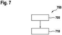
- Fig. 7 shows a flowchart of a method 700 for monitoring a sanding process for a sanding system for a rail vehicle according to an exemplary embodiment.
- This procedure 700 is from one of the in one of the Figures 1 or 2 Controllable or executable devices described.
- the method 700 has a step 705 of reading and a step 710 of determining.
- a grinding signal is read in, which represents a grinding process sensed by a sensor device, which represents grinding of at least one grain of grit in a wheel rail gap between a rail and a wheel of the rail vehicle.
- a grit amount signal is determined using the grinding signal, which indicates a grit amount of ground grit grains during the sanding process.
Landscapes
- Engineering & Computer Science (AREA)
- Physics & Mathematics (AREA)
- Electromagnetism (AREA)
- Transportation (AREA)
- Mechanical Engineering (AREA)
- Machines For Laying And Maintaining Railways (AREA)
Claims (15)
- Système (115) de contrôle d'une opération (400) de sablage d'une installation (110) de sablage pour un véhicule (100) ferroviaire, caractérisé en ce que le système (115) a les caractéristiques suivantes :
un dispositif (170) d'analyse, qui est constitué pour lire un signal (175) de broyage, qui représente, détectée par un dispositif (180) capteur, une opération de broyage, qui représente un broyage d'au moins un grain d'agent d'épandage dans un intervalle (135) roue - rail entre un rail (145) et une roue (140) du véhicule (100) ferroviaire, et qui est constitué pour déterminer, en utilisant le signal (175) de broyage, un signal (185) de quantité d'agents d'épandage, qui indiquent une quantité d'agent d'épandage en grains d'agent d'épandage broyés pendant l'opération (400) de sablage. - Système (115) suivant la revendication 1, comprenant le dispositif (180) capteur, qui est constitué pour détecter l'opération de broyage et pour disposer du signal (175) de broyage représentant l'opération de broyage détectée.
- Système (115) suivant l'une des revendications précédentes, dans lequel le dispositif (180) capteur est constitué pour détecter une accélération d'un élément (140, 150) du véhicule (100) ferroviaire ou d'un élément (205) de rail d'un dispositif (200) de rail et/ou une onde sonore et/ou un signal acoustique.
- Système (115) suivant l'une des revendications précédentes, comprenant un dispositif (225) d'envoi, qui est constitué pour envoyer le signal (185) de quantité d'agent d'épandage à une commande (160) du véhicule (100) ferroviaire.
- Système (115) suivant l'une des revendications précédentes, dans lequel le dispositif (170) d'analyse est constitué pour analyser l'amplitude et/ou la fréquence (Hz) du signal (175) de broyage, afin de déterminer le signal (185) de quantité d'agent d'épandage.
- Système (115) suivant l'une des revendications précédentes, dans lequel le dispositif (170) d'analyse est constitué pour comparer le signal (175) de broyage à une valeur limite d'amplitude fixée, afin de détecter l'opération de broyage et/ou de déterminer et d'analyser un spectre (600, 605) de fréquence du signal (175) de broyage, afin de déterminer la quantité d'agent d'épandage broyée.
- Système (115) suivant la revendication 6, dans lequel le dispositif (170) d'analyse est constitué pour analyser le spectre (600, 605) de fréquence, afin de déterminer la quantité d'agent d'épandage broyée dans un laps de temps déterminé ou dans toute l'opération (400) de sablage.
- Système (115) suivant l'une des revendications précédentes, comprenant un dispositif (190) de comparaison, qui est constitué pour, en utilisant le signal (185) de quantité d'agent d'épandage et un signal de consigne de quantité d'agent d'épandage, qui représente une quantité escomptée d'agent d'épandage en grains broyés d'agent d'épandage, donner un signal (192) d'alerte, si la quantité d'agent d'épandage en grains broyée d'agent d'épandage s'écarte de la quantité souhaitée d'agent d'épandage en grains d'agents d'épandage broyés et/ou donner un signal d'actionnement, si la quantité d'agent d'épandage en grains d'agent d'épandage broyée correspond à la quantité d'agent d'épandage en grains d'agent d'épandage broyés.
- Système (115) suivant la revendication 8, dans lequel le signal (192) d'alerte est constitué pour indiquer, à un conducteur (195) du véhicule (100) ferroviaire, une information sur une quantité incorrecte d'agent d'épandage broyée.
- Système (115) suivant l'une des revendications précédentes, dans lequel le dispositif (180) capteur et le dispositif (170) d'analyse sont formés en une pièce ou sont formés en au moins deux pièces distinctes.
- Système (105) de sablage pour un véhicule (100) ferroviaire, dans lequel le système (105) de sablage a une installation (110) de sablage et un système (115) suivant l'une des revendications précédentes.
- Véhicule (100) ferroviaire ayant un système (105) de sablage suivant la revendication 11.
- Véhicule (100) ferroviaire suivant la revendication 12, dans lequel au moins le dispositif (180) capteur est monté sur ou dans un palier (150) d'essieu, un essieu, une roue (140), un bogie (155) et/ou une infrastructure du véhicule (100) ferroviaire.
- Système (200) de voie comprenant un élément (205) de rail et un système (115) suivant l'une des revendications 1 à 10, dans lequel au moins le dispositif (180) capteur est monté sur ou dans l'élément (205) de rail.
- Procédé (700) de contrôle d'une opération (400) d'une installation (110) de sablage pour un véhicule (100) ferroviaire, caractérisé en ce que le procédé (700) a au moins les stades suivants :lecture (705) d'un signal (175) de broyage, qui représente une opération, détectée par un dispositif (180) capteur, de broyage, qui représente un broyage d'au moins un grain d'agent d'épandage dans un intervalle (135) roue - rail entre un rail (145) et une roue (140) du véhicule (100) ferroviaire ; etdétermination (710) d'un signal (185) de quantité d'agent d'épandage, qui indique une quantité d'agent d'épandage en grains d'agents d'épandage broyés pendant l'opération (400) de sablage, en utilisant le signal (175) de broyage.
Applications Claiming Priority (2)
| Application Number | Priority Date | Filing Date | Title |
|---|---|---|---|
| DE102019123233.3A DE102019123233B3 (de) | 2019-08-29 | 2019-08-29 | Vorrichtung und Verfahren zum Überwachen eines Sandungsvorgangs für eine Sandungsanlage für ein Schienenfahrzeug, Sandungsvorrichtung, Schienenfahrzeug und Gleisvorrichtung |
| PCT/EP2020/073965 WO2021037974A1 (fr) | 2019-08-29 | 2020-08-27 | Dispositif et procédé pour surveiller un processus de sablage pour une installation de sablage pour un véhicule sur rails, dispositif de sablage, véhicule sur rails et ensemble voie |
Publications (2)
| Publication Number | Publication Date |
|---|---|
| EP4021776A1 EP4021776A1 (fr) | 2022-07-06 |
| EP4021776B1 true EP4021776B1 (fr) | 2023-09-27 |
Family
ID=72340329
Family Applications (1)
| Application Number | Title | Priority Date | Filing Date |
|---|---|---|---|
| EP20765229.8A Active EP4021776B1 (fr) | 2019-08-29 | 2020-08-27 | Dispositif et procédé pour surveiller un processus de sablage pour une installation de sablage pour un véhicule sur rails, dispositif de sablage, véhicule sur rails et ensemble voie |
Country Status (3)
| Country | Link |
|---|---|
| EP (1) | EP4021776B1 (fr) |
| DE (1) | DE102019123233B3 (fr) |
| WO (1) | WO2021037974A1 (fr) |
Families Citing this family (2)
| Publication number | Priority date | Publication date | Assignee | Title |
|---|---|---|---|---|
| DE102023201757A1 (de) * | 2023-02-27 | 2024-08-29 | Siemens Mobility GmbH | Verfahren zur Überwachung der Funktionsfähigkeit einer Sandungsanlage eines Schienenfahrzeugs |
| CN121180250B (zh) * | 2025-11-25 | 2026-02-17 | 华铁西屋法维莱(青岛)交通设备有限公司 | 一种轨道车辆撒砂清砂控制系统及其控制方法 |
Family Cites Families (6)
| Publication number | Priority date | Publication date | Assignee | Title |
|---|---|---|---|---|
| AT503513B8 (de) * | 2004-02-11 | 2009-01-15 | Faiveley Transport | Einrichtung zur überwachung des flusses von streugut in fahrzeugen |
| DE102011113085B4 (de) * | 2011-09-09 | 2014-12-24 | Knorr-Bremse Systeme für Schienenfahrzeuge GmbH | Partikelstreuanlage für ein Schienenfahrzeug |
| DE102013100250A1 (de) * | 2013-01-11 | 2014-07-31 | Knorr-Bremse Systeme für Schienenfahrzeuge GmbH | Verfahren und Vorrichtung zum Analysieren eines Streumittels und zum Steuern eines Aufbringens eines Streumittels auf eine Schiene für ein Schienenfahrzeug |
| DE102013016135B4 (de) * | 2013-09-27 | 2019-07-18 | Knorr-Bremse Systeme für Schienenfahrzeuge GmbH | Vorrichtung und Verfahren zum Verbessern eines Haftwerts zwischen einem Rad und einer Schiene für ein Schienenfahrzeug |
| DE202014104155U1 (de) * | 2014-02-04 | 2014-09-15 | Ibeg Systems Gmbh | Vorrichtung zur Durchflussüberwachung von körnigen Materialien, Sandstreuvorrichtung für Fahrzeuge sowie Fahrzeug mit einer solchen Sandstreuvorrichtung |
| DE202014104156U1 (de) * | 2014-02-04 | 2014-09-15 | Ibeg Systems Gmbh | Vorrichtung zur Überwachung des Flusses von mittels Druckluft beförderten flüssigen oder festen Medien, insbesondere Sand, Sandstreuvorrichtung für Fahrzeuge sowie Fahrzeug mit einer solchen Sandstreuvorrichtung |
-
2019
- 2019-08-29 DE DE102019123233.3A patent/DE102019123233B3/de active Active
-
2020
- 2020-08-27 WO PCT/EP2020/073965 patent/WO2021037974A1/fr not_active Ceased
- 2020-08-27 EP EP20765229.8A patent/EP4021776B1/fr active Active
Also Published As
| Publication number | Publication date |
|---|---|
| WO2021037974A1 (fr) | 2021-03-04 |
| DE102019123233B3 (de) | 2021-02-25 |
| EP4021776A1 (fr) | 2022-07-06 |
Similar Documents
| Publication | Publication Date | Title |
|---|---|---|
| DE102015106400B4 (de) | Sensoranordnung zum Erkennen eines Zustands einer Fahrbahn mit zumindest zwei Ultraschallsensoren, Fahrerassistenzsystem, Kraftfahrzeug sowie dazugehöriges Verfahren | |
| EP3288804B1 (fr) | Ensemble de détection pour détecter l'état d'une chaussée, comprenant un détecteur à ultrasons, système d'assistance au conducteur, véhicule à moteur et procédé associé | |
| DE102008047473B4 (de) | Verfahren und Vorrichtung zur Lokalisierung eines defekten Bauteils eines Fahrzeugs | |
| EP4021776B1 (fr) | Dispositif et procédé pour surveiller un processus de sablage pour une installation de sablage pour un véhicule sur rails, dispositif de sablage, véhicule sur rails et ensemble voie | |
| EP2478346A1 (fr) | Procédé et dispositif pour la surveillance du comportement en déplacement d'un véhicule ferroviaire | |
| EP1183174A1 (fr) | Procede et dispositif pour la surveillance d'un vehicule ou d'une voie de circulation pendant la circulation de service du vehicule | |
| EP2943386B1 (fr) | Procédé et dispositif permettant d'analyser un matériau d'épandage et de commander l'application d'un matériau d'épandage sur un rail pour un véhicule ferroviaire | |
| DE102013009516A1 (de) | Klimatisierungsvorrichtung für ein Fahrzeug, insbesondere Kraftfahrzeug und Verfahren zu deren Betrieb | |
| EP2101156A2 (fr) | Procédé et dispositif destinés à la surveillance de systèmes de réglage de châssis | |
| DE102019204609A1 (de) | Verfahren zum Ermitteln eines Fahrbahnzustands während eines Fahrbetriebs eines Fahrzeugs | |
| EP3602119B1 (fr) | Procédé de détection d'un objet dans une zone environnante d'un véhicule à moteur avec classification de l'objet, dispositif de capteur ultrasonique et véhicule à moteur | |
| DE102008049224A1 (de) | Verfahren und Vorrichtung zum Überprüfen mindestens eines Laufwerks eines auf einem Gleis fahrbaren Schienenfahrzeugs auf einen Defekt | |
| EP1422119A1 (fr) | Capteur de déraillement à induction | |
| DE102015120533B4 (de) | Einrichtung und Verfahren zur akustischen Verkehrsdatenerfassung | |
| EP1226060B1 (fr) | Procede pour commander la distribution de lubrifiant | |
| DE102006028004B4 (de) | Schienenfahrzeug mit Schotterflug-Erfassung | |
| DE10037849A1 (de) | Verfahren und Vorrichtung zum Beeinflussen eines Betriebsparameters eines Kraftfahrzeugs | |
| DE202014104156U1 (de) | Vorrichtung zur Überwachung des Flusses von mittels Druckluft beförderten flüssigen oder festen Medien, insbesondere Sand, Sandstreuvorrichtung für Fahrzeuge sowie Fahrzeug mit einer solchen Sandstreuvorrichtung | |
| DE102021123586A1 (de) | Verfahren und Vorrichtung zur akustischen Beurteilung von Komponenten eines Kraftfahrzeuges | |
| DE102020005023A1 (de) | Verfahren und Vorrichtung zur Erkennung von Anomalien während einer Fahrzeugnutzung | |
| DE102004034749A1 (de) | Diagnosevorrichtung für ein Kraftfahrzeug, geeignet zur Ortung und Speicherung von unerwünschten vom Fahrzeugführer im Fahrgastinnenraum wahrnehmbaren Störgeräuschen | |
| DE102012224111A1 (de) | Verfahren zum Überwachen eines Fahrzeugstoßdämpfers | |
| DE102014112742A1 (de) | Vorrichtung und Verfahren zur Durchflussüberwachung von körnigen Materialien, Sandstreuvorrichtung für Fahrzeuge sowie Fahrzeug mit einer solchen Sandstreuvorrichtung | |
| DE102019207343A1 (de) | Verfahren und Vorrichtung zur Erkennung einer nassen oder feuchten Fahrbahn, Computerproduktprogramm und Speichermedium | |
| DE102019206741A1 (de) | Vorrichtung und Verfahren zum Erkennen von Fremdkörpern in und/oder an Fahrzeugreifen |
Legal Events
| Date | Code | Title | Description |
|---|---|---|---|
| STAA | Information on the status of an ep patent application or granted ep patent |
Free format text: STATUS: UNKNOWN |
|
| STAA | Information on the status of an ep patent application or granted ep patent |
Free format text: STATUS: THE INTERNATIONAL PUBLICATION HAS BEEN MADE |
|
| PUAI | Public reference made under article 153(3) epc to a published international application that has entered the european phase |
Free format text: ORIGINAL CODE: 0009012 |
|
| STAA | Information on the status of an ep patent application or granted ep patent |
Free format text: STATUS: REQUEST FOR EXAMINATION WAS MADE |
|
| 17P | Request for examination filed |
Effective date: 20220221 |
|
| AK | Designated contracting states |
Kind code of ref document: A1 Designated state(s): AL AT BE BG CH CY CZ DE DK EE ES FI FR GB GR HR HU IE IS IT LI LT LU LV MC MK MT NL NO PL PT RO RS SE SI SK SM TR |
|
| DAV | Request for validation of the european patent (deleted) | ||
| DAX | Request for extension of the european patent (deleted) | ||
| GRAP | Despatch of communication of intention to grant a patent |
Free format text: ORIGINAL CODE: EPIDOSNIGR1 |
|
| STAA | Information on the status of an ep patent application or granted ep patent |
Free format text: STATUS: GRANT OF PATENT IS INTENDED |
|
| INTG | Intention to grant announced |
Effective date: 20230406 |
|
| GRAS | Grant fee paid |
Free format text: ORIGINAL CODE: EPIDOSNIGR3 |
|
| GRAA | (expected) grant |
Free format text: ORIGINAL CODE: 0009210 |
|
| STAA | Information on the status of an ep patent application or granted ep patent |
Free format text: STATUS: THE PATENT HAS BEEN GRANTED |
|
| AK | Designated contracting states |
Kind code of ref document: B1 Designated state(s): AL AT BE BG CH CY CZ DE DK EE ES FI FR GB GR HR HU IE IS IT LI LT LU LV MC MK MT NL NO PL PT RO RS SE SI SK SM TR |
|
| REG | Reference to a national code |
Ref country code: GB Ref legal event code: FG4D Free format text: NOT ENGLISH |
|
| REG | Reference to a national code |
Ref country code: CH Ref legal event code: EP |
|
| REG | Reference to a national code |
Ref country code: DE Ref legal event code: R096 Ref document number: 502020005435 Country of ref document: DE |
|
| REG | Reference to a national code |
Ref country code: IE Ref legal event code: FG4D Free format text: LANGUAGE OF EP DOCUMENT: GERMAN |
|
| REG | Reference to a national code |
Ref country code: SE Ref legal event code: TRGR |
|
| REG | Reference to a national code |
Ref country code: LT Ref legal event code: MG9D |
|
| PG25 | Lapsed in a contracting state [announced via postgrant information from national office to epo] |
Ref country code: GR Free format text: LAPSE BECAUSE OF FAILURE TO SUBMIT A TRANSLATION OF THE DESCRIPTION OR TO PAY THE FEE WITHIN THE PRESCRIBED TIME-LIMIT Effective date: 20231228 |
|
| PG25 | Lapsed in a contracting state [announced via postgrant information from national office to epo] |
Ref country code: RS Free format text: LAPSE BECAUSE OF FAILURE TO SUBMIT A TRANSLATION OF THE DESCRIPTION OR TO PAY THE FEE WITHIN THE PRESCRIBED TIME-LIMIT Effective date: 20230927 Ref country code: NO Free format text: LAPSE BECAUSE OF FAILURE TO SUBMIT A TRANSLATION OF THE DESCRIPTION OR TO PAY THE FEE WITHIN THE PRESCRIBED TIME-LIMIT Effective date: 20231227 Ref country code: LV Free format text: LAPSE BECAUSE OF FAILURE TO SUBMIT A TRANSLATION OF THE DESCRIPTION OR TO PAY THE FEE WITHIN THE PRESCRIBED TIME-LIMIT Effective date: 20230927 Ref country code: LT Free format text: LAPSE BECAUSE OF FAILURE TO SUBMIT A TRANSLATION OF THE DESCRIPTION OR TO PAY THE FEE WITHIN THE PRESCRIBED TIME-LIMIT Effective date: 20230927 Ref country code: HR Free format text: LAPSE BECAUSE OF FAILURE TO SUBMIT A TRANSLATION OF THE DESCRIPTION OR TO PAY THE FEE WITHIN THE PRESCRIBED TIME-LIMIT Effective date: 20230927 Ref country code: GR Free format text: LAPSE BECAUSE OF FAILURE TO SUBMIT A TRANSLATION OF THE DESCRIPTION OR TO PAY THE FEE WITHIN THE PRESCRIBED TIME-LIMIT Effective date: 20231228 Ref country code: FI Free format text: LAPSE BECAUSE OF FAILURE TO SUBMIT A TRANSLATION OF THE DESCRIPTION OR TO PAY THE FEE WITHIN THE PRESCRIBED TIME-LIMIT Effective date: 20230927 |
|
| REG | Reference to a national code |
Ref country code: NL Ref legal event code: MP Effective date: 20230927 |
|
| PG25 | Lapsed in a contracting state [announced via postgrant information from national office to epo] |
Ref country code: NL Free format text: LAPSE BECAUSE OF FAILURE TO SUBMIT A TRANSLATION OF THE DESCRIPTION OR TO PAY THE FEE WITHIN THE PRESCRIBED TIME-LIMIT Effective date: 20230927 |
|
| PG25 | Lapsed in a contracting state [announced via postgrant information from national office to epo] |
Ref country code: IS Free format text: LAPSE BECAUSE OF FAILURE TO SUBMIT A TRANSLATION OF THE DESCRIPTION OR TO PAY THE FEE WITHIN THE PRESCRIBED TIME-LIMIT Effective date: 20240127 |
|
| PG25 | Lapsed in a contracting state [announced via postgrant information from national office to epo] |
Ref country code: ES Free format text: LAPSE BECAUSE OF FAILURE TO SUBMIT A TRANSLATION OF THE DESCRIPTION OR TO PAY THE FEE WITHIN THE PRESCRIBED TIME-LIMIT Effective date: 20230927 |
|
| PG25 | Lapsed in a contracting state [announced via postgrant information from national office to epo] |
Ref country code: SM Free format text: LAPSE BECAUSE OF FAILURE TO SUBMIT A TRANSLATION OF THE DESCRIPTION OR TO PAY THE FEE WITHIN THE PRESCRIBED TIME-LIMIT Effective date: 20230927 Ref country code: RO Free format text: LAPSE BECAUSE OF FAILURE TO SUBMIT A TRANSLATION OF THE DESCRIPTION OR TO PAY THE FEE WITHIN THE PRESCRIBED TIME-LIMIT Effective date: 20230927 Ref country code: IS Free format text: LAPSE BECAUSE OF FAILURE TO SUBMIT A TRANSLATION OF THE DESCRIPTION OR TO PAY THE FEE WITHIN THE PRESCRIBED TIME-LIMIT Effective date: 20240127 Ref country code: ES Free format text: LAPSE BECAUSE OF FAILURE TO SUBMIT A TRANSLATION OF THE DESCRIPTION OR TO PAY THE FEE WITHIN THE PRESCRIBED TIME-LIMIT Effective date: 20230927 Ref country code: EE Free format text: LAPSE BECAUSE OF FAILURE TO SUBMIT A TRANSLATION OF THE DESCRIPTION OR TO PAY THE FEE WITHIN THE PRESCRIBED TIME-LIMIT Effective date: 20230927 Ref country code: CZ Free format text: LAPSE BECAUSE OF FAILURE TO SUBMIT A TRANSLATION OF THE DESCRIPTION OR TO PAY THE FEE WITHIN THE PRESCRIBED TIME-LIMIT Effective date: 20230927 Ref country code: PT Free format text: LAPSE BECAUSE OF FAILURE TO SUBMIT A TRANSLATION OF THE DESCRIPTION OR TO PAY THE FEE WITHIN THE PRESCRIBED TIME-LIMIT Effective date: 20240129 Ref country code: SK Free format text: LAPSE BECAUSE OF FAILURE TO SUBMIT A TRANSLATION OF THE DESCRIPTION OR TO PAY THE FEE WITHIN THE PRESCRIBED TIME-LIMIT Effective date: 20230927 |
|
| P01 | Opt-out of the competence of the unified patent court (upc) registered |
Effective date: 20240424 |
|
| PG25 | Lapsed in a contracting state [announced via postgrant information from national office to epo] |
Ref country code: PL Free format text: LAPSE BECAUSE OF FAILURE TO SUBMIT A TRANSLATION OF THE DESCRIPTION OR TO PAY THE FEE WITHIN THE PRESCRIBED TIME-LIMIT Effective date: 20230927 |
|
| REG | Reference to a national code |
Ref country code: DE Ref legal event code: R097 Ref document number: 502020005435 Country of ref document: DE |
|
| PG25 | Lapsed in a contracting state [announced via postgrant information from national office to epo] |
Ref country code: DK Free format text: LAPSE BECAUSE OF FAILURE TO SUBMIT A TRANSLATION OF THE DESCRIPTION OR TO PAY THE FEE WITHIN THE PRESCRIBED TIME-LIMIT Effective date: 20230927 |
|
| PG25 | Lapsed in a contracting state [announced via postgrant information from national office to epo] |
Ref country code: DK Free format text: LAPSE BECAUSE OF FAILURE TO SUBMIT A TRANSLATION OF THE DESCRIPTION OR TO PAY THE FEE WITHIN THE PRESCRIBED TIME-LIMIT Effective date: 20230927 |
|
| PLBE | No opposition filed within time limit |
Free format text: ORIGINAL CODE: 0009261 |
|
| STAA | Information on the status of an ep patent application or granted ep patent |
Free format text: STATUS: NO OPPOSITION FILED WITHIN TIME LIMIT |
|
| 26N | No opposition filed |
Effective date: 20240628 |
|
| PG25 | Lapsed in a contracting state [announced via postgrant information from national office to epo] |
Ref country code: SI Free format text: LAPSE BECAUSE OF FAILURE TO SUBMIT A TRANSLATION OF THE DESCRIPTION OR TO PAY THE FEE WITHIN THE PRESCRIBED TIME-LIMIT Effective date: 20230927 |
|
| PG25 | Lapsed in a contracting state [announced via postgrant information from national office to epo] |
Ref country code: SI Free format text: LAPSE BECAUSE OF FAILURE TO SUBMIT A TRANSLATION OF THE DESCRIPTION OR TO PAY THE FEE WITHIN THE PRESCRIBED TIME-LIMIT Effective date: 20230927 |
|
| PG25 | Lapsed in a contracting state [announced via postgrant information from national office to epo] |
Ref country code: BG Free format text: LAPSE BECAUSE OF FAILURE TO SUBMIT A TRANSLATION OF THE DESCRIPTION OR TO PAY THE FEE WITHIN THE PRESCRIBED TIME-LIMIT Effective date: 20230927 |
|
| PG25 | Lapsed in a contracting state [announced via postgrant information from national office to epo] |
Ref country code: BG Free format text: LAPSE BECAUSE OF FAILURE TO SUBMIT A TRANSLATION OF THE DESCRIPTION OR TO PAY THE FEE WITHIN THE PRESCRIBED TIME-LIMIT Effective date: 20230927 |
|
| REG | Reference to a national code |
Ref country code: CH Ref legal event code: PL |
|
| PG25 | Lapsed in a contracting state [announced via postgrant information from national office to epo] |
Ref country code: LU Free format text: LAPSE BECAUSE OF NON-PAYMENT OF DUE FEES Effective date: 20240827 |
|
| PG25 | Lapsed in a contracting state [announced via postgrant information from national office to epo] |
Ref country code: MC Free format text: LAPSE BECAUSE OF FAILURE TO SUBMIT A TRANSLATION OF THE DESCRIPTION OR TO PAY THE FEE WITHIN THE PRESCRIBED TIME-LIMIT Effective date: 20230927 Ref country code: CH Free format text: LAPSE BECAUSE OF NON-PAYMENT OF DUE FEES Effective date: 20240831 |
|
| REG | Reference to a national code |
Ref country code: BE Ref legal event code: MM Effective date: 20240831 |
|
| PG25 | Lapsed in a contracting state [announced via postgrant information from national office to epo] |
Ref country code: BE Free format text: LAPSE BECAUSE OF NON-PAYMENT OF DUE FEES Effective date: 20240831 |
|
| PG25 | Lapsed in a contracting state [announced via postgrant information from national office to epo] |
Ref country code: IE Free format text: LAPSE BECAUSE OF NON-PAYMENT OF DUE FEES Effective date: 20240827 |
|
| PGFP | Annual fee paid to national office [announced via postgrant information from national office to epo] |
Ref country code: DE Payment date: 20250827 Year of fee payment: 6 |
|
| PGFP | Annual fee paid to national office [announced via postgrant information from national office to epo] |
Ref country code: IT Payment date: 20250821 Year of fee payment: 6 |
|
| PGFP | Annual fee paid to national office [announced via postgrant information from national office to epo] |
Ref country code: GB Payment date: 20250826 Year of fee payment: 6 |
|
| PGFP | Annual fee paid to national office [announced via postgrant information from national office to epo] |
Ref country code: AT Payment date: 20251020 Year of fee payment: 5 Ref country code: FR Payment date: 20250819 Year of fee payment: 6 |
|
| PGFP | Annual fee paid to national office [announced via postgrant information from national office to epo] |
Ref country code: SE Payment date: 20250825 Year of fee payment: 6 |
|
| PG25 | Lapsed in a contracting state [announced via postgrant information from national office to epo] |
Ref country code: CY Free format text: LAPSE BECAUSE OF FAILURE TO SUBMIT A TRANSLATION OF THE DESCRIPTION OR TO PAY THE FEE WITHIN THE PRESCRIBED TIME-LIMIT; INVALID AB INITIO Effective date: 20200827 |
|
| PG25 | Lapsed in a contracting state [announced via postgrant information from national office to epo] |
Ref country code: HU Free format text: LAPSE BECAUSE OF FAILURE TO SUBMIT A TRANSLATION OF THE DESCRIPTION OR TO PAY THE FEE WITHIN THE PRESCRIBED TIME-LIMIT; INVALID AB INITIO Effective date: 20200827 |