EP4021804B1 - Système de manutention des conteneurs dans un véhicule et véhicule avec un tel système - Google Patents
Système de manutention des conteneurs dans un véhicule et véhicule avec un tel système Download PDFInfo
- Publication number
- EP4021804B1 EP4021804B1 EP20764596.1A EP20764596A EP4021804B1 EP 4021804 B1 EP4021804 B1 EP 4021804B1 EP 20764596 A EP20764596 A EP 20764596A EP 4021804 B1 EP4021804 B1 EP 4021804B1
- Authority
- EP
- European Patent Office
- Prior art keywords
- receiving space
- driver
- container
- spindle
- handling system
- Prior art date
- Legal status (The legal status is an assumption and is not a legal conclusion. Google has not performed a legal analysis and makes no representation as to the accuracy of the status listed.)
- Active
Links
Images



Classifications
-
- B—PERFORMING OPERATIONS; TRANSPORTING
- B62—LAND VEHICLES FOR TRAVELLING OTHERWISE THAN ON RAILS
- B62B—HAND-PROPELLED VEHICLES, e.g. HAND CARTS OR PERAMBULATORS; SLEDGES
- B62B3/00—Hand carts having more than one axis carrying transport wheels; Steering devices therefor; Equipment therefor
- B62B3/14—Hand carts having more than one axis carrying transport wheels; Steering devices therefor; Equipment therefor characterised by provisions for nesting or stacking, e.g. shopping trolleys
- B62B3/1404—Means for facilitating stowing or transporting of the trolleys; Antitheft arrangements
-
- B—PERFORMING OPERATIONS; TRANSPORTING
- B64—AIRCRAFT; AVIATION; COSMONAUTICS
- B64D—EQUIPMENT FOR FITTING IN OR TO AIRCRAFT; FLIGHT SUITS; PARACHUTES; ARRANGEMENT OR MOUNTING OF POWER PLANTS OR PROPULSION TRANSMISSIONS IN AIRCRAFT
- B64D11/00—Passenger or crew accommodation; Flight-deck installations not otherwise provided for
- B64D11/0007—Devices specially adapted for food or beverage distribution services
-
- B—PERFORMING OPERATIONS; TRANSPORTING
- B64—AIRCRAFT; AVIATION; COSMONAUTICS
- B64D—EQUIPMENT FOR FITTING IN OR TO AIRCRAFT; FLIGHT SUITS; PARACHUTES; ARRANGEMENT OR MOUNTING OF POWER PLANTS OR PROPULSION TRANSMISSIONS IN AIRCRAFT
- B64D11/00—Passenger or crew accommodation; Flight-deck installations not otherwise provided for
- B64D11/04—Galleys
Definitions
- the invention relates to a handling system for containers in a vehicle and a vehicle with such a system.
- Vehicles that are used to transport a large number of passengers are usually equipped with cabins with passenger seats, one or more on-board toilets and optionally one or more on-board galleys.
- parking spaces are used for serving trolleys in which several Serving trolleys can be arranged one behind the other.
- this refers to the use of trolleys conforming to ATLAS, ARINC or KSSU standards and the combined use of a full-depth trolley and a half-size trolley or two Serving trolley with full construction depth (two "full size trolleys).
- Even for supply containers that have to be stored as boxes in the galley it may be possible to stow two boxes or more one behind the other due to the construction depth for the storage room.
- a user To remove serving trolleys from such a parking space, a user usually grabs a handle located on a front side of the serving trolley and pulls it out of the parking space.
- the serving trolley is equipped with rollers that are intended for movement within the kitchen area as well as for the serving process within the aircraft cabin to move the serving trolley from row to row of seats in the longitudinal aisle of the aircraft.
- a removal device must be provided for serving trolleys in the rear parking spaces. Particularly if a full-size trolley is parked in a rear parking space, it may require greater effort and accessibility for the flight attendant to move the full-size trolley out of the rear parking space.
- An object of the invention is therefore to propose a device or an on-board kitchen with which food containers arranged one behind the other in a receiving space can be easily handled by on-board personnel, so that, in particular, food containers arranged at the rear in a receiving space can be reached as easily as possible.
- a handling system for a receiving space in a vehicle for storing containers which provides a linear guide arranged on a side wall or an underside of a cover plate of the receiving space.
- the linear guide guides at least one driver element along the direction of movement of the container, with the storage position of the container with its rear wall being provided in the area of the rear wall of the receiving space and the removal position in the area of an insertion opening, arranged opposite one another to the rear wall.
- the at least one driver element is in operative connection with at least one spindle nut of a spindle drive. This moves the container linearly from a stowage and storage position of the container into a removal position of the container and vice versa.
- the rear wall of the receiving space which is arranged opposite the insertion opening, or also an end stop, is a rear boundary of a parking space in the receiving space, against which a rearmost container abuts or comes into contact or is adjacent. This corresponds to the storage position of the supply container.
- the size and shape of the container can be selected depending on the requirements in the vehicle. If the vehicle is realized as a commercial aircraft, the use of serving trolleys according to relevant standards, such as the ATLAS standard, is recommended.
- the advantages according to the invention also become particularly clear when the rollable containers have a depth that is greater than 30 to 40 cm. Especially with a full-size trolley that is approximately 80 to 85 cm long.
- the receiving space for receiving at least two containers arranged one behind the other is provided with a front parking space and a rear parking space, the linear guide extending essentially from the insertion opening in the area of the front parking space to essentially the rear wall of the receiving space.
- the rear container After a conventional removal of a front container, which is arranged at the insertion opening, the rear container, which is arranged at a clear distance from the insertion opening in the interior of the receiving space, can be removed using the handling system.
- the handling system For supply containers, for example serving trolleys, which are arranged in the rear parking spaces of a galley in a vehicle, is preferred the handling system according to the invention is provided. Particularly when a full-size trolley is parked in a rear parking space, it is a great relief for the flight attendants to use the handling system to position the relatively heavy container in an easily accessible access area and to transport it out of the rear parking space in a simple manner.
- the spindle drive can preferably be provided with at least one threaded spindle.
- a single threaded spindle which is operatively connected to a spindle nut, can be provided for converting a rotary movement into a linear movement for moving the at least one driver element.
- two parallel threaded spindles are also possible, between which the at least one driver element is mounted. Depending on the available installation space, you can choose between possible spindle drive designs.
- the spindle drive according to a second embodiment is equipped with two threaded spindles, which are operatively connected via a gear transmission.
- not only one driver element is provided.
- the at least one driver element forms a driver arrangement with a front driver.
- the front and rear drivers are connected to one another via a support plate, this driver arrangement being movable in the linear guide.
- the front driver is designed to be rotatable or displaceable in order to Retracting the supply container into the receiving space to be able to be removed from the movement space.
- the spindle drive can be driven via a crank drive.
- the threaded spindle is preferably designed as a trapezoidal spindle with a pitch of 25 mm to 100 mm.
- a "full-size trolley" a gradient of 40 mm to 80 mm can be advantageous. With just a few turns of the hand crank, this enables a linear movement that moves a container from the front parking space to the storage position to the rear parking space or vice versa.
- the handling system can advantageously be equipped with a crank drive, the crank drive having a crank rod and a hand crank and the crank rod being connected in a rotationally fixed manner to at least one threaded spindle.
- the spindle drive with a spindle motor and thus cause the threaded spindle to rotate.
- Electric motor drives are conceivable for this.
- the invention further relates to a vehicle, in particular an aircraft, with a cabin and a cabin monument located therein, which has a handling system according to the previous description.
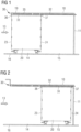
- the Figures 1 and 2 show a recording room 10 with two trolley spaces 14 and 15 arranged one behind the other. Rollable supply containers 20 can be placed and secured on these trolley spaces.
- the vehicle in this exemplary embodiment is a commercial aircraft
- the rollable supply containers 20 are therefore designed as serving carts, so-called trolleys. These are so-called “full-size trolleys”, i.e. serving trolleys with a full depth of approximately 80 cm.
- the receiving space 10 is usually fully closed and has an insertion opening 13 accessible. It can be part of a galley, also commonly known as a galley. It has a bottom 16. This floor 16 can be part of an aircraft cabin floor or a galley floor.
- the rear trolley parking space 15 is provided in the receiving space 10 shown so that a rear supply container with its rear container wall 24 is arranged adjacent or adjacent to the rear wall 11 of the receiving space 10 in the storage position.
- the front trolley parking space 14 and the rear trolley parking space 15 are aligned along a common longitudinal axis.
- the front supply container 20 is positioned exactly in front of the rear supply container (not shown) from the perspective of the insertion opening, so that the removal of the rear supply container from the storage position is only possible if the front supply container 20 is removed and thus the front one Trolley space 14 is free. Access via the insertion opening 13 to the rear trolley space 15 is difficult or not possible without aids due to the limited arm reach when handled by the flight attendants. Even if this arrangement of trolley parking spaces in a commercial aircraft is not preferred from the point of view of usability, structural constraints can lead to an optimized use of space in the limited space of a commercial aircraft if such supply containers can also be arranged one behind the other.
- a handling system 30 is provided for this parking space 15.
- This first embodiment of the handling system 30 essentially has a linear guide 32. It is arranged in the area of the cover plate 19 of the receiving space 10. The linear guide 32 is attached to the cover plate 19 with fastening points.
- the cover plate 19 is also the worktop of the kitchen.
- at least one driver 36 can move along the linear guide 32, which preferably engages from above on the front container wall 23 of the container 20 and thus moves the container 20 from the front parking space 14 to the rear parking space 15.
- the front driver 36 is connected to a rear driver 37 via a support plate 38.
- a driver arrangement 35 these components form the movable displacement element on or in the linear guide 32.
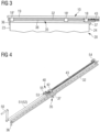
- Fig. 3 shows a detail of the handling system 30 in the receiving space 10 in the area of the cover plate 19 in a side view.
- the driver arrangement 35 is preferably mounted on at least two carriages in the linear guide 32.
- the driver arrangement 35, together with the rear driver 37, also has a stop for the supply container 20.
- the supply container 20 is retracted with its rear wall 24 up to the driver 37. This is adjustable, as in Fig. 15 shown.
- the front driver 36 is brought into the stop position with the supply container 20, preferably with the front wall 23, by moving or rotating.
- FIG. 4 the handling system 30 according to the invention is shown in a perspective view.
- the handling system 30 includes the linear guide 32, in which the driver arrangement 35 with the front driver 36 and rear driver 37 is slidably mounted.
- the rear driver 36 is firmly connected to a spindle nut 42 of a spindle drive 40.
- the spindle nut 42 can move linearly on a threaded spindle 43.
- the spindle drive 40 is shown in the Embodiment driven via a hand crank 50 and crank rod 51. The rotational movement of the hand crank 50 and the crank rod 51 is used to convert this into a translational movement and thus to move the driver arrangement 35 within the linear guide 32.
- the threaded spindle 43 is preferably designed as a trapezoidal spindle with a pitch of 25 mm to 100 mm. With just a few turns of the hand crank 50, this enables a linear movement that moves a “full-size trolley” 20 from the front parking space 14 to the storage position on the rear parking space 15. A pitch of 40 mm to 80 mm has proven to be preferred.
- the crank rod 51 is connected to the threaded spindle 43 in a rotationally fixed manner.
- the connecting element 53 is more precise Fig. 9 shown.
- Fig. 5 shows the handling system 30 according to the invention in a perspective view from behind and Fig. 6 shows a perspective view of the handling system 30 according to the invention in operative connection of drivers 36 and 37 with the supply container. 20.
- the drivers 36 and 37 are connected to one another via the carrier plate 38 in such a way that they correspond to the overall depth of a supply container 20 and thus the front driver 36 on the front wall 23 of the container 20 and the rear driver 37 on the rear Container wall 24 can attack. This ensures that the supply container 20 is guided securely by the driver arrangement 35.
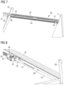
- Fig. 7 shows an embodiment of the handling system 30 according to the invention with the detail of the driver arrangement 35. It can also be seen how the integration of the handling system 30 into the receiving space 10 can take place. For this purpose, a view from below of the handling system 30 is shown.
- the attachment of the handling system 30 is realized on the one hand in the rear part of the receiving space 10 in the area of the rear wall 11.
- the linear guide 32 and the spindle drive 40 with the threaded spindle 43 run essentially parallel along the direction of movement of the food container 20 below the cover plate 19 (not shown in this figure).
- the threaded spindle 43 is rotatably fixed to the rear wall 11 by means of a fastening fitting/flange bearing 54.
- the threaded spindle 43 is mounted via a further flange bearing 55 on the underside of the cover plate 19, for example on a support element 18. In addition to the fixation at the rear end, the threaded spindle 43 is held on the carrier element 18 in the middle area of the receiving space 10.
- the position of the further flange 55 on the underside of the cover plate 19 is selected.
- FIGS 8 and 9 show the spindle drive 40 in further details in a perspective view.
- the threaded spindle 43 is connected to the crank rod 51 in a rotationally fixed manner.
- the threaded spindle 43 and the crank rod 51 are connected via a threaded connection 53 and secured with a pin 56.
- the storage of the front end of the threaded spindle 43 is made possible by means of the flange bearing 55.
- the flange bearing 55 is attached to a support element 18 by means of fastening elements 57 (see Figure 7 ) attached.
- the carrier element 18 can also be replaced by directly attaching the flange 55 to the underside of the cover plate 19.
- crank rod 51 can be designed to be telescopic.
- a connecting rod tube 52 is connected to a foldable hand crank 50.
- the connecting rod tube 52 is connected to the connecting rod 51, for example by means of a key-groove connection 58.
- the crank rod 51 can be inserted into the crank rod tube 52.
- the handle 50 can also be designed to be removable and stored in an easily accessible access area for the flight attendants in the galley.
- Fig. 10 is shown in a perspective view of the supply container 20 on the rear parking space 15 of the receiving space 10 in operative connection with the handling system 30.
- the receiving space 10 is only represented by the rear wall 11 and parts of the cover plate 19, here with support elements 18, 18 'and 18".
- the support element 18 is used as a fastening point for the front flange bearing 55 for supporting the threaded spindle 43 as well as the support element 18' Attachment point for the connecting rod tube 52 is provided.
- the support element 18" represents the front edge of the cover plate 19, which also contains at least one attachment point for the connecting rod tube 52 and the linear guide 32.
- FIG. 11 ff shows a handling system 300 according to a second embodiment.
- the supply container 20 is shown in operative connection with the handling system 300 arranged on a side wall 130 of the receiving space 100.
- the handling system 30 according to the first embodiment can also be provided on a side wall 130. Appropriate positions can be provided depending on the available installation space.
- Fig. 11 shows the handling system 300 according to the invention in a side view
- Fig. 12 shows the handling system 300 according to the invention in a perspective view.
- the operating principle of the handling system 300 is essentially identical to the previously described system according to the first embodiment shown in, with a spindle drive 400 and a linear guide 320 Figures 1 to 10 . Due to the structural relocation of the system 300 into the side wall area of the receiving space 10, a narrower design is advantageous, which is accompanied by a change in the spindle drive 40. This is However, it must be dimensioned based on the loads to be taken into account, the forces and torques that occur and the handling forces to be used.
- the spindle drive 400 is equipped with two threaded spindles 430, 431, which are operatively connected via a gear transmission 440. This may result in a lighter design.
- a driver arrangement 350 is moved along the guide rail 320 via a crank rod 510 and a hand crank 500.
- the spindle nuts 420 and 421 are firmly connected to the rear driver 360.
- the driver arrangement 350 is shown in detail as part of the handling system 300.
- the handling system 300 is attached to the side wall 120 of the receiving space 100.
- the driver arrangement 350 is moved with movement carriage 330 on the linear guide 320.
- a carrier plate 380 is provided, which connects the front driver 360 to the rear driver 370 and also rotatably supports the front driver 360.
- the carrier plate 380 is preferably strip-shaped in order to hold the corresponding drivers 360 and 370 along the longitudinal extent of the supply container 20.
- the front driver 360 can be rotated into a stop position on the front wall 23 of the container 20 after the supply container 20 has moved into the receiving space 100. Then the supply container 20 is moved into its storage position via the driver arrangement 350 or from the storage position into the removal position. When the removal position of the supply container 20 is reached, the driver 360 is rotated so that it moves out of the travel path of the supply container 20 and the supply container 20 can be removed.
- the spindle drive 400 is equipped with two threaded spindles 430, 431, which are operatively connected via a gear transmission 440.
- the two longitudinal threaded spindles 430 and 431 with an intermediate linear guide 320 that runs essentially parallel to the threaded spindles can be dimensioned smaller than the threaded spindle 43 according to the first embodiment in order to move the supply container 20.
- Parts of the driver arrangement 350 in particular a rear driver 370, are positioned between the spindle nuts 420, 421. Due to this arrangement of the fixed driver 370 between the spindle nuts 420, 421, high moments that could act on the driver 370 when the supply container 20 is displaced can be avoided.
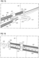
- Fig. 15 also shows the rear driver 370 in an adjustable embodiment. Fine positioning between the spindle nuts 420 and 421 can be carried out via an elongated hole. A bumper 371 is also provided, which provides protection when it hits the rear wall.
- Fig. 16 also shows the rotation-proof connection of the crank rod 510 with one of the threaded spindles, shown here with the threaded spindle 430.
- the rotation of the second threaded spindle 431 is ensured via the gear arrangement 443, 442 and 441, which are in Fig. 17 is evident...
- the components shown can therefore be used to implement a simple, yet very effective handling system, which can significantly increase the compactness of a galley or other facilities, because a parking space with sufficient depth can be filled with several serving trolleys one behind the other, without the restrictions imposed by the Handling of a user of average height requires consideration.
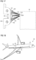
- FIG. 18 an aircraft 60 with a fuselage 61 and a cabin 62 formed therein, in which a cabin monument 63 can be arranged, which has a receiving space 10 for supply containers and is equipped with a handling system 30 according to the invention.
- the receiving space 10 is part of a galley of a commercial aircraft and the cover plate 19 can also be used as a worktop in the galley.
Landscapes
- Engineering & Computer Science (AREA)
- Aviation & Aerospace Engineering (AREA)
- Chemical & Material Sciences (AREA)
- Combustion & Propulsion (AREA)
- Transportation (AREA)
- Mechanical Engineering (AREA)
- Handcart (AREA)
Claims (8)
- Système (30) de manutention de conteneurs (20) pour un espace de réception (10, 100), comprenant :un guide linéaire (32, 320) qui est apte à être agencé sur une paroi latérale (110) ou une face inférieure d'un panneau supérieur (19) de l'espace de réception (10, 100),le guide linéaire (32, 320) guidant au moins un organe d'entraînement (37, 370) le long de la direction de déplacement du conteneur (20),la position de stockage du conteneur (20) avec sa paroi arrière (24) pouvant être prévue dans la zone de la paroi arrière (11, 110) de l'espace de réception (10, 100), et la position de prélèvement pouvant être prévue dans la zone d'une ouverture d'insertion (13), agencée à l'opposé de la paroi arrière (11, 110) de l'espace de réception,ledit au moins un organe d'entraînement (37, 370) étant en liaison fonctionnelle avec au moins un écrou de broche (42, 420, 421) d'un système d'entraînement à broche (40, 400), qui déplace linéairement le conteneur (20) depuis une position de rangement et de stockage du conteneur (20) dans une position de prélèvement du conteneur (20) et inversement,caractérisé en ce que ledit au moins un organe d'entraînement (37, 370) forme un organe d'entraînement arrière et est relié à un organe d'entraînement avant (36, 360) par l'intermédiaire d'une plaque de support (38, 380), cet ensemble d'organes d'entraînement (35, 350) étant mobile dans le guide linéaire (32, 320),l'organe d'entraînement arrière (37, 370) étant agencé de manière réglable sur ledit au moins un écrou de broche (42, 420, 421) via un trou oblong, etl'organe d'entraînement avant (36, 360) étant conçu de manière à pouvoir être tourné ou déplacé, afin d'être apte à être retiré d'un espace de déplacement lorsque le conteneur (20) est déplacé dans l'espace de réception (10, 100).
- Système (30) selon la revendication 1,
dans lequel l'espace de réception (10, 110) est conçu de façon à recevoir au moins deux conteneurs (20) agencés l'un derrière l'autre avec un emplacement avant (14) et un emplacement arrière (15), le guidage linéaire (32) s'étendant essentiellement de l'ouverture d'insertion (13) dans la zone de l'emplacement avant (14) jusqu'à essentiellement la paroi arrière (11, 110) de l'espace de réception (10, 100). - Système (30) selon l'une des revendications 1 ou 2, dans lequel le système d'entraînement à broche (40, 400) comprend au moins une broche filetée (43, 430, 431).
- Système (30) selon l'une des revendications 1 à 3,
présentant deux broches filetées (430, 431) parallèles, entre lesquelles est monté ledit au moins un organe d'entraînement (37, 370). - Système (30) selon l'une des revendications 1 à 4,
le système d'entraînement à broche (40, 400, 43, 430, 431) étant entraîné par un système d'entraînement à manivelle (50, 51, 500, 510). - Système (30) selon la revendication 5,
dans lequel l'système d'entraînement à manivelle présente une tige de manivelle (51, 510) ainsi qu'une manivelle (50, 500) et la tige de manivelle (51, 510) est reliée de manière solidaire en rotation à au moins une broche filetée (43, 430). - Système (30) selon l'une des revendications 1 à 5,
dans lequel le système d'entraînement à broche (40, 400) comprend un moteur électrique. - Véhicule (60), de préférence un avion de ligne, comprenant une cabine (62) et un monument de cabine (63) situé à l'intérieur de celle-ci et comprenant un espace de réception (10, 100), qui comprend un système (30) de manutention selon l'une des revendications 1 à 7.
Applications Claiming Priority (2)
| Application Number | Priority Date | Filing Date | Title |
|---|---|---|---|
| DE102019123107.8A DE102019123107A1 (de) | 2019-08-28 | 2019-08-28 | Handhabungssystem für Behälter in einem Fahrzeug sowie ein Fahrzeug mit einem derartigen System |
| PCT/EP2020/073717 WO2021037836A1 (fr) | 2019-08-28 | 2020-08-25 | Système de manipulation pour contenant dans un véhicule et véhicule comportant un tel système |
Publications (2)
| Publication Number | Publication Date |
|---|---|
| EP4021804A1 EP4021804A1 (fr) | 2022-07-06 |
| EP4021804B1 true EP4021804B1 (fr) | 2024-02-28 |
Family
ID=72292498
Family Applications (1)
| Application Number | Title | Priority Date | Filing Date |
|---|---|---|---|
| EP20764596.1A Active EP4021804B1 (fr) | 2019-08-28 | 2020-08-25 | Système de manutention des conteneurs dans un véhicule et véhicule avec un tel système |
Country Status (4)
| Country | Link |
|---|---|
| US (1) | US12128941B2 (fr) |
| EP (1) | EP4021804B1 (fr) |
| DE (1) | DE102019123107A1 (fr) |
| WO (1) | WO2021037836A1 (fr) |
Families Citing this family (7)
| Publication number | Priority date | Publication date | Assignee | Title |
|---|---|---|---|---|
| DE102019123107A1 (de) * | 2019-08-28 | 2021-03-04 | Airbus Operations Gmbh | Handhabungssystem für Behälter in einem Fahrzeug sowie ein Fahrzeug mit einem derartigen System |
| EP4144644B1 (fr) * | 2021-09-07 | 2026-01-21 | B/E Aerospace (UK) Limited | Dispositif d'extraction de chariot |
| US20230139044A1 (en) * | 2021-11-03 | 2023-05-04 | The Boeing Company | Coupling systems and methods for carts |
| US12240607B2 (en) * | 2023-01-27 | 2025-03-04 | B/E Aerospace, Inc. | Retracting T divider |
| EP4556368A1 (fr) * | 2023-11-16 | 2025-05-21 | B/E Aerospace, Inc. | Ensemble de retenue |
| EP4559812A1 (fr) * | 2023-11-21 | 2025-05-28 | B/E Aerospace (UK) Limited | Dispositif de retenue |
| EP4640557A1 (fr) * | 2024-04-23 | 2025-10-29 | B/E Aerospace Inc. | Dispositif de retenue de demi-cart télescopique |
Family Cites Families (24)
| Publication number | Priority date | Publication date | Assignee | Title |
|---|---|---|---|---|
| CH256988A (de) * | 1947-06-13 | 1948-09-15 | Hans Ingold | Einrichtung zum Lagern von Gegenständen. |
| US2923584A (en) * | 1955-09-12 | 1960-02-02 | Jr Frederick J Broderick | Cabinet assembly |
| US3168361A (en) * | 1962-04-26 | 1965-02-02 | Elecompack Co Ltd | Shiftable stack assembly |
| US3597034A (en) * | 1969-07-14 | 1971-08-03 | Justin J Wetzler | Storage system |
| CA2167034C (fr) * | 1995-01-20 | 2004-07-06 | Steven L. Janson | Mecanisme de verrouillage automatique d'un dispositif de stockage mobile |
| US6152287A (en) * | 1996-08-06 | 2000-11-28 | Fuselage Engineering Services, Ltd. | Compact storing and retrieving apparatus particularly useful for aircraft |
| US5938047A (en) * | 1998-03-27 | 1999-08-17 | Ellis; Chris | Material storage and retrieval assembly |
| US8190289B2 (en) * | 2003-10-17 | 2012-05-29 | Rock-Tenn Shared Services, Llc | Dispensing and display system |
| EP1955894A3 (fr) * | 2007-02-12 | 2009-09-30 | Hubert Faller | Dispositif de transport |
| US8662606B2 (en) * | 2011-03-17 | 2014-03-04 | Mckesson Automation Inc. | Drawer assembly and associated method for controllably limiting the slideable extension of a drawer |
| DE202012102254U1 (de) * | 2012-06-19 | 2013-09-25 | Dewertokin Gmbh | Linearantrieb |
| FR2999546B1 (fr) * | 2012-12-14 | 2016-10-14 | Airbus Operations Sas | Meuble pour aeronef comportant des moyens de distribution d'un chariot entre deux parties |
| EP2956361B1 (fr) * | 2013-02-13 | 2017-03-29 | Sell Gmbh | Avion |
| GB201303032D0 (en) * | 2013-02-21 | 2013-04-03 | Gray Matter Alpha Ltd | Merchandise presentation |
| US10315767B2 (en) * | 2014-04-02 | 2019-06-11 | B/E Aerospace, Inc. | Vacuum powered actuation mechanism for a vertically stowable aircraft storage unit |
| WO2016034531A1 (fr) * | 2014-09-05 | 2016-03-10 | Sell Gmbh | Agencement de chariots d'une cuisine d'un véhicule, en particulier un avion |
| DE102017117293A1 (de) * | 2017-07-31 | 2019-01-31 | Airbus Operations Gmbh | Verstau- und Entnahmesystem für rollbare Behälter in einem Fahrzeug sowie ein Fahrzeug, insbesondere ein Verkehrsflugzeug mit einem derartigen System |
| US10850847B2 (en) * | 2017-08-31 | 2020-12-01 | Safran Cabin Netherlands N.v. | Slide extractor braking system |
| US10710858B2 (en) * | 2018-09-12 | 2020-07-14 | Actron Manufacturing, Inc. | Extractor for beverage baskets |
| DE102019108747A1 (de) * | 2019-04-03 | 2020-10-08 | Airbus Operations Gmbh | Verstau- und Entnahmesystem für rollbare Behälter in einem Fahrzeug sowie ein Fahrzeug mit einem derartigen System |
| DE102019108750A1 (de) * | 2019-04-03 | 2020-10-08 | Airbus Operations Gmbh | Aufnahmesystem für rollbare Behälter in einem Fahrzeug sowie ein Fahrzeug mit einem derartigen System |
| US11420748B2 (en) * | 2019-08-16 | 2022-08-23 | B/E Aerospace, Inc. | Galley cart extraction and retention system for multiple-cart bays |
| DE102019123107A1 (de) * | 2019-08-28 | 2021-03-04 | Airbus Operations Gmbh | Handhabungssystem für Behälter in einem Fahrzeug sowie ein Fahrzeug mit einem derartigen System |
| EP4144644B1 (fr) * | 2021-09-07 | 2026-01-21 | B/E Aerospace (UK) Limited | Dispositif d'extraction de chariot |
-
2019
- 2019-08-28 DE DE102019123107.8A patent/DE102019123107A1/de active Pending
-
2020
- 2020-08-25 WO PCT/EP2020/073717 patent/WO2021037836A1/fr not_active Ceased
- 2020-08-25 EP EP20764596.1A patent/EP4021804B1/fr active Active
-
2021
- 2021-11-28 US US17/536,057 patent/US12128941B2/en active Active
Also Published As
| Publication number | Publication date |
|---|---|
| WO2021037836A1 (fr) | 2021-03-04 |
| EP4021804A1 (fr) | 2022-07-06 |
| DE102019123107A1 (de) | 2021-03-04 |
| US20220153329A1 (en) | 2022-05-19 |
| US12128941B2 (en) | 2024-10-29 |
Similar Documents
| Publication | Publication Date | Title |
|---|---|---|
| EP4021804B1 (fr) | Système de manutention des conteneurs dans un véhicule et véhicule avec un tel système | |
| EP3112266B1 (fr) | Systeme de module sanitaire a installer dans une cabine d'avion | |
| DE69404818T2 (de) | Umwandelbare und in Raumbedarf bezüglich einer Verschiebungsachse veränderbare Vielfach-Sitz-Struktur | |
| EP2853446B1 (fr) | Recouvrement de l'espace de chargement | |
| DE102011011704A1 (de) | Modulares Kabinensegment, Kabine für ein Fahrzeug und Fahrzeug mit einer Kabine | |
| DE102021115039A1 (de) | Kraftfahrzeug mit teleskopheckklappe | |
| DE102017117293A1 (de) | Verstau- und Entnahmesystem für rollbare Behälter in einem Fahrzeug sowie ein Fahrzeug, insbesondere ein Verkehrsflugzeug mit einem derartigen System | |
| EP1177948B1 (fr) | Couvercle pour le compartiment de charge d'un véhicule, notamment pour véhicule familial | |
| EP4126669B1 (fr) | Région de véhicule dotée d'un compartiment à bagages et d'un panneau de recouvrement au-dessus du compartiment à bagages, et procédé de montage et de démontage d'un panneau de recouvrement au-dessus du compartiment à bagages | |
| EP3718888B1 (fr) | Système de réception pour récipients roulants dans un véhicule ainsi que véhicule doté d'un tel système | |
| EP3718889B1 (fr) | Système de rangement et de soutirage pour récipients roulants dans un véhicule ainsi que véhicule doté d'un tel système | |
| EP1876056B1 (fr) | Dispositif de recouvrement de coffre et véhicule avec dispositif de recouvrement de coffre | |
| DE102014205998B4 (de) | Abdeckeinrichtung für einen Gepäckraum eines Kraftwagens | |
| EP4457119B1 (fr) | Siège pliant pour véhicule | |
| DE3734707C2 (fr) | ||
| EP3718890B1 (fr) | Système de rangement et de soutirage pour récipients roulants dans un véhicule ainsi que véhicule doté d'un tel système | |
| DE102016109722A1 (de) | Anordnung zum bedarfsweisen Arretieren eines Servierwagens in einer Kabine eines Transportmittels | |
| EP1356991A2 (fr) | Dispositif de sécurité pour véhicules, tel que volet cache-bagages, filet de séparation, etc | |
| DE102019121933A1 (de) | Verstau- und Entnahmesystem für Behälter in einem Fahrzeug sowie ein Fahrzeug mit einem derartigen System | |
| EP0644083A1 (fr) | Espace de rangement pour véhicule de camping | |
| DE102015102025B4 (de) | Laderaumabdeckung | |
| EP3932746B1 (fr) | Dispositif d'arrimage pour une caravane et caravane dotée du dispositif d'arrimage | |
| DE102023118795A1 (de) | Dachträgersystem für ein Fahrzeugdach eines Kraftwagens | |
| DE102024001163A1 (de) | Aufbewahrungsbehälter in einer Armaturentafel eines Fahrzeuges | |
| DE102024122672A1 (de) | Variabler Gepäckraum für ein Kraftfahrzeug sowie Kraftfahrzeug mit variablem Gepäckraum |
Legal Events
| Date | Code | Title | Description |
|---|---|---|---|
| STAA | Information on the status of an ep patent application or granted ep patent |
Free format text: STATUS: UNKNOWN |
|
| STAA | Information on the status of an ep patent application or granted ep patent |
Free format text: STATUS: THE INTERNATIONAL PUBLICATION HAS BEEN MADE |
|
| PUAI | Public reference made under article 153(3) epc to a published international application that has entered the european phase |
Free format text: ORIGINAL CODE: 0009012 |
|
| STAA | Information on the status of an ep patent application or granted ep patent |
Free format text: STATUS: REQUEST FOR EXAMINATION WAS MADE |
|
| 17P | Request for examination filed |
Effective date: 20211130 |
|
| AK | Designated contracting states |
Kind code of ref document: A1 Designated state(s): AL AT BE BG CH CY CZ DE DK EE ES FI FR GB GR HR HU IE IS IT LI LT LU LV MC MK MT NL NO PL PT RO RS SE SI SK SM TR |
|
| RAP3 | Party data changed (applicant data changed or rights of an application transferred) |
Owner name: AIRBUS OPERATIONS GMBH |
|
| DAV | Request for validation of the european patent (deleted) | ||
| DAX | Request for extension of the european patent (deleted) | ||
| GRAP | Despatch of communication of intention to grant a patent |
Free format text: ORIGINAL CODE: EPIDOSNIGR1 |
|
| STAA | Information on the status of an ep patent application or granted ep patent |
Free format text: STATUS: GRANT OF PATENT IS INTENDED |
|
| INTG | Intention to grant announced |
Effective date: 20230922 |
|
| GRAS | Grant fee paid |
Free format text: ORIGINAL CODE: EPIDOSNIGR3 |
|
| GRAA | (expected) grant |
Free format text: ORIGINAL CODE: 0009210 |
|
| STAA | Information on the status of an ep patent application or granted ep patent |
Free format text: STATUS: THE PATENT HAS BEEN GRANTED |
|
| AK | Designated contracting states |
Kind code of ref document: B1 Designated state(s): AL AT BE BG CH CY CZ DE DK EE ES FI FR GB GR HR HU IE IS IT LI LT LU LV MC MK MT NL NO PL PT RO RS SE SI SK SM TR |
|
| REG | Reference to a national code |
Ref country code: GB Ref legal event code: FG4D Free format text: NOT ENGLISH |
|
| REG | Reference to a national code |
Ref country code: CH Ref legal event code: EP |
|
| REG | Reference to a national code |
Ref country code: DE Ref legal event code: R096 Ref document number: 502020007188 Country of ref document: DE |
|
| REG | Reference to a national code |
Ref country code: IE Ref legal event code: FG4D Free format text: LANGUAGE OF EP DOCUMENT: GERMAN |
|
| REG | Reference to a national code |
Ref country code: LT Ref legal event code: MG9D |
|
| PG25 | Lapsed in a contracting state [announced via postgrant information from national office to epo] |
Ref country code: IS Free format text: LAPSE BECAUSE OF FAILURE TO SUBMIT A TRANSLATION OF THE DESCRIPTION OR TO PAY THE FEE WITHIN THE PRESCRIBED TIME-LIMIT Effective date: 20240628 |
|
| REG | Reference to a national code |
Ref country code: NL Ref legal event code: MP Effective date: 20240228 |
|
| PG25 | Lapsed in a contracting state [announced via postgrant information from national office to epo] |
Ref country code: LT Free format text: LAPSE BECAUSE OF FAILURE TO SUBMIT A TRANSLATION OF THE DESCRIPTION OR TO PAY THE FEE WITHIN THE PRESCRIBED TIME-LIMIT Effective date: 20240228 |
|
| PG25 | Lapsed in a contracting state [announced via postgrant information from national office to epo] |
Ref country code: GR Free format text: LAPSE BECAUSE OF FAILURE TO SUBMIT A TRANSLATION OF THE DESCRIPTION OR TO PAY THE FEE WITHIN THE PRESCRIBED TIME-LIMIT Effective date: 20240529 |
|
| PG25 | Lapsed in a contracting state [announced via postgrant information from national office to epo] |
Ref country code: RS Free format text: LAPSE BECAUSE OF FAILURE TO SUBMIT A TRANSLATION OF THE DESCRIPTION OR TO PAY THE FEE WITHIN THE PRESCRIBED TIME-LIMIT Effective date: 20240528 Ref country code: HR Free format text: LAPSE BECAUSE OF FAILURE TO SUBMIT A TRANSLATION OF THE DESCRIPTION OR TO PAY THE FEE WITHIN THE PRESCRIBED TIME-LIMIT Effective date: 20240228 Ref country code: NL Free format text: LAPSE BECAUSE OF FAILURE TO SUBMIT A TRANSLATION OF THE DESCRIPTION OR TO PAY THE FEE WITHIN THE PRESCRIBED TIME-LIMIT Effective date: 20240228 |
|
| PG25 | Lapsed in a contracting state [announced via postgrant information from national office to epo] |
Ref country code: ES Free format text: LAPSE BECAUSE OF FAILURE TO SUBMIT A TRANSLATION OF THE DESCRIPTION OR TO PAY THE FEE WITHIN THE PRESCRIBED TIME-LIMIT Effective date: 20240228 |
|
| PG25 | Lapsed in a contracting state [announced via postgrant information from national office to epo] |
Ref country code: RS Free format text: LAPSE BECAUSE OF FAILURE TO SUBMIT A TRANSLATION OF THE DESCRIPTION OR TO PAY THE FEE WITHIN THE PRESCRIBED TIME-LIMIT Effective date: 20240528 Ref country code: NO Free format text: LAPSE BECAUSE OF FAILURE TO SUBMIT A TRANSLATION OF THE DESCRIPTION OR TO PAY THE FEE WITHIN THE PRESCRIBED TIME-LIMIT Effective date: 20240528 Ref country code: NL Free format text: LAPSE BECAUSE OF FAILURE TO SUBMIT A TRANSLATION OF THE DESCRIPTION OR TO PAY THE FEE WITHIN THE PRESCRIBED TIME-LIMIT Effective date: 20240228 Ref country code: LT Free format text: LAPSE BECAUSE OF FAILURE TO SUBMIT A TRANSLATION OF THE DESCRIPTION OR TO PAY THE FEE WITHIN THE PRESCRIBED TIME-LIMIT Effective date: 20240228 Ref country code: IS Free format text: LAPSE BECAUSE OF FAILURE TO SUBMIT A TRANSLATION OF THE DESCRIPTION OR TO PAY THE FEE WITHIN THE PRESCRIBED TIME-LIMIT Effective date: 20240628 Ref country code: HR Free format text: LAPSE BECAUSE OF FAILURE TO SUBMIT A TRANSLATION OF THE DESCRIPTION OR TO PAY THE FEE WITHIN THE PRESCRIBED TIME-LIMIT Effective date: 20240228 Ref country code: GR Free format text: LAPSE BECAUSE OF FAILURE TO SUBMIT A TRANSLATION OF THE DESCRIPTION OR TO PAY THE FEE WITHIN THE PRESCRIBED TIME-LIMIT Effective date: 20240529 Ref country code: FI Free format text: LAPSE BECAUSE OF FAILURE TO SUBMIT A TRANSLATION OF THE DESCRIPTION OR TO PAY THE FEE WITHIN THE PRESCRIBED TIME-LIMIT Effective date: 20240228 Ref country code: ES Free format text: LAPSE BECAUSE OF FAILURE TO SUBMIT A TRANSLATION OF THE DESCRIPTION OR TO PAY THE FEE WITHIN THE PRESCRIBED TIME-LIMIT Effective date: 20240228 Ref country code: BG Free format text: LAPSE BECAUSE OF FAILURE TO SUBMIT A TRANSLATION OF THE DESCRIPTION OR TO PAY THE FEE WITHIN THE PRESCRIBED TIME-LIMIT Effective date: 20240228 |
|
| PG25 | Lapsed in a contracting state [announced via postgrant information from national office to epo] |
Ref country code: PL Free format text: LAPSE BECAUSE OF FAILURE TO SUBMIT A TRANSLATION OF THE DESCRIPTION OR TO PAY THE FEE WITHIN THE PRESCRIBED TIME-LIMIT Effective date: 20240228 Ref country code: PT Free format text: LAPSE BECAUSE OF FAILURE TO SUBMIT A TRANSLATION OF THE DESCRIPTION OR TO PAY THE FEE WITHIN THE PRESCRIBED TIME-LIMIT Effective date: 20240628 |
|
| PG25 | Lapsed in a contracting state [announced via postgrant information from national office to epo] |
Ref country code: SE Free format text: LAPSE BECAUSE OF FAILURE TO SUBMIT A TRANSLATION OF THE DESCRIPTION OR TO PAY THE FEE WITHIN THE PRESCRIBED TIME-LIMIT Effective date: 20240228 Ref country code: PT Free format text: LAPSE BECAUSE OF FAILURE TO SUBMIT A TRANSLATION OF THE DESCRIPTION OR TO PAY THE FEE WITHIN THE PRESCRIBED TIME-LIMIT Effective date: 20240628 Ref country code: PL Free format text: LAPSE BECAUSE OF FAILURE TO SUBMIT A TRANSLATION OF THE DESCRIPTION OR TO PAY THE FEE WITHIN THE PRESCRIBED TIME-LIMIT Effective date: 20240228 Ref country code: LV Free format text: LAPSE BECAUSE OF FAILURE TO SUBMIT A TRANSLATION OF THE DESCRIPTION OR TO PAY THE FEE WITHIN THE PRESCRIBED TIME-LIMIT Effective date: 20240228 |
|
| PG25 | Lapsed in a contracting state [announced via postgrant information from national office to epo] |
Ref country code: DK Free format text: LAPSE BECAUSE OF FAILURE TO SUBMIT A TRANSLATION OF THE DESCRIPTION OR TO PAY THE FEE WITHIN THE PRESCRIBED TIME-LIMIT Effective date: 20240228 |
|
| PG25 | Lapsed in a contracting state [announced via postgrant information from national office to epo] |
Ref country code: SM Free format text: LAPSE BECAUSE OF FAILURE TO SUBMIT A TRANSLATION OF THE DESCRIPTION OR TO PAY THE FEE WITHIN THE PRESCRIBED TIME-LIMIT Effective date: 20240228 |
|
| PG25 | Lapsed in a contracting state [announced via postgrant information from national office to epo] |
Ref country code: EE Free format text: LAPSE BECAUSE OF FAILURE TO SUBMIT A TRANSLATION OF THE DESCRIPTION OR TO PAY THE FEE WITHIN THE PRESCRIBED TIME-LIMIT Effective date: 20240228 Ref country code: CZ Free format text: LAPSE BECAUSE OF FAILURE TO SUBMIT A TRANSLATION OF THE DESCRIPTION OR TO PAY THE FEE WITHIN THE PRESCRIBED TIME-LIMIT Effective date: 20240228 |
|
| PG25 | Lapsed in a contracting state [announced via postgrant information from national office to epo] |
Ref country code: SK Free format text: LAPSE BECAUSE OF FAILURE TO SUBMIT A TRANSLATION OF THE DESCRIPTION OR TO PAY THE FEE WITHIN THE PRESCRIBED TIME-LIMIT Effective date: 20240228 |
|
| PG25 | Lapsed in a contracting state [announced via postgrant information from national office to epo] |
Ref country code: SM Free format text: LAPSE BECAUSE OF FAILURE TO SUBMIT A TRANSLATION OF THE DESCRIPTION OR TO PAY THE FEE WITHIN THE PRESCRIBED TIME-LIMIT Effective date: 20240228 Ref country code: SK Free format text: LAPSE BECAUSE OF FAILURE TO SUBMIT A TRANSLATION OF THE DESCRIPTION OR TO PAY THE FEE WITHIN THE PRESCRIBED TIME-LIMIT Effective date: 20240228 Ref country code: RO Free format text: LAPSE BECAUSE OF FAILURE TO SUBMIT A TRANSLATION OF THE DESCRIPTION OR TO PAY THE FEE WITHIN THE PRESCRIBED TIME-LIMIT Effective date: 20240228 Ref country code: EE Free format text: LAPSE BECAUSE OF FAILURE TO SUBMIT A TRANSLATION OF THE DESCRIPTION OR TO PAY THE FEE WITHIN THE PRESCRIBED TIME-LIMIT Effective date: 20240228 Ref country code: DK Free format text: LAPSE BECAUSE OF FAILURE TO SUBMIT A TRANSLATION OF THE DESCRIPTION OR TO PAY THE FEE WITHIN THE PRESCRIBED TIME-LIMIT Effective date: 20240228 Ref country code: CZ Free format text: LAPSE BECAUSE OF FAILURE TO SUBMIT A TRANSLATION OF THE DESCRIPTION OR TO PAY THE FEE WITHIN THE PRESCRIBED TIME-LIMIT Effective date: 20240228 |
|
| REG | Reference to a national code |
Ref country code: DE Ref legal event code: R097 Ref document number: 502020007188 Country of ref document: DE |
|
| PG25 | Lapsed in a contracting state [announced via postgrant information from national office to epo] |
Ref country code: IT Free format text: LAPSE BECAUSE OF FAILURE TO SUBMIT A TRANSLATION OF THE DESCRIPTION OR TO PAY THE FEE WITHIN THE PRESCRIBED TIME-LIMIT Effective date: 20240228 |
|
| PG25 | Lapsed in a contracting state [announced via postgrant information from national office to epo] |
Ref country code: IT Free format text: LAPSE BECAUSE OF FAILURE TO SUBMIT A TRANSLATION OF THE DESCRIPTION OR TO PAY THE FEE WITHIN THE PRESCRIBED TIME-LIMIT Effective date: 20240228 |
|
| PLBE | No opposition filed within time limit |
Free format text: ORIGINAL CODE: 0009261 |
|
| STAA | Information on the status of an ep patent application or granted ep patent |
Free format text: STATUS: NO OPPOSITION FILED WITHIN TIME LIMIT |
|
| 26N | No opposition filed |
Effective date: 20241129 |
|
| REG | Reference to a national code |
Ref country code: CH Ref legal event code: PL |
|
| PG25 | Lapsed in a contracting state [announced via postgrant information from national office to epo] |
Ref country code: LU Free format text: LAPSE BECAUSE OF NON-PAYMENT OF DUE FEES Effective date: 20240825 |
|
| PG25 | Lapsed in a contracting state [announced via postgrant information from national office to epo] |
Ref country code: SI Free format text: LAPSE BECAUSE OF FAILURE TO SUBMIT A TRANSLATION OF THE DESCRIPTION OR TO PAY THE FEE WITHIN THE PRESCRIBED TIME-LIMIT Effective date: 20240228 Ref country code: CH Free format text: LAPSE BECAUSE OF NON-PAYMENT OF DUE FEES Effective date: 20240831 Ref country code: MC Free format text: LAPSE BECAUSE OF FAILURE TO SUBMIT A TRANSLATION OF THE DESCRIPTION OR TO PAY THE FEE WITHIN THE PRESCRIBED TIME-LIMIT Effective date: 20240228 |
|
| REG | Reference to a national code |
Ref country code: BE Ref legal event code: MM Effective date: 20240831 |
|
| PG25 | Lapsed in a contracting state [announced via postgrant information from national office to epo] |
Ref country code: BE Free format text: LAPSE BECAUSE OF NON-PAYMENT OF DUE FEES Effective date: 20240831 |
|
| PG25 | Lapsed in a contracting state [announced via postgrant information from national office to epo] |
Ref country code: IE Free format text: LAPSE BECAUSE OF NON-PAYMENT OF DUE FEES Effective date: 20240825 |
|
| PGFP | Annual fee paid to national office [announced via postgrant information from national office to epo] |
Ref country code: DE Payment date: 20250820 Year of fee payment: 6 |
|
| PGFP | Annual fee paid to national office [announced via postgrant information from national office to epo] |
Ref country code: GB Payment date: 20250820 Year of fee payment: 6 |
|
| PGFP | Annual fee paid to national office [announced via postgrant information from national office to epo] |
Ref country code: AT Payment date: 20251020 Year of fee payment: 5 Ref country code: FR Payment date: 20250828 Year of fee payment: 6 |
|
| PG25 | Lapsed in a contracting state [announced via postgrant information from national office to epo] |
Ref country code: CY Free format text: LAPSE BECAUSE OF FAILURE TO SUBMIT A TRANSLATION OF THE DESCRIPTION OR TO PAY THE FEE WITHIN THE PRESCRIBED TIME-LIMIT; INVALID AB INITIO Effective date: 20200825 |
|
| PG25 | Lapsed in a contracting state [announced via postgrant information from national office to epo] |
Ref country code: HU Free format text: LAPSE BECAUSE OF FAILURE TO SUBMIT A TRANSLATION OF THE DESCRIPTION OR TO PAY THE FEE WITHIN THE PRESCRIBED TIME-LIMIT; INVALID AB INITIO Effective date: 20200825 |