EP4022898B1 - Dispositif d'affichage à champ de lumière, procédé de rendu de pixels ajusté à cet effet, et système et procédé de perception de la vision ajustés l'utilisant adressant l'astigmatisme ou des pathologies similaires - Google Patents
Dispositif d'affichage à champ de lumière, procédé de rendu de pixels ajusté à cet effet, et système et procédé de perception de la vision ajustés l'utilisant adressant l'astigmatisme ou des pathologies similaires Download PDFInfo
- Publication number
- EP4022898B1 EP4022898B1 EP20775939.0A EP20775939A EP4022898B1 EP 4022898 B1 EP4022898 B1 EP 4022898B1 EP 20775939 A EP20775939 A EP 20775939A EP 4022898 B1 EP4022898 B1 EP 4022898B1
- Authority
- EP
- European Patent Office
- Prior art keywords
- given
- image
- pixel
- designated
- pupil
- Prior art date
- Legal status (The legal status is an assumption and is not a legal conclusion. Google has not performed a legal analysis and makes no representation as to the accuracy of the status listed.)
- Active
Links
Images


Classifications
-
- A—HUMAN NECESSITIES
- A61—MEDICAL OR VETERINARY SCIENCE; HYGIENE
- A61B—DIAGNOSIS; SURGERY; IDENTIFICATION
- A61B3/00—Apparatus for testing the eyes; Instruments for examining the eyes
- A61B3/0016—Operational features thereof
- A61B3/0025—Operational features thereof characterised by electronic signal processing, e.g. eye models
-
- A—HUMAN NECESSITIES
- A61—MEDICAL OR VETERINARY SCIENCE; HYGIENE
- A61B—DIAGNOSIS; SURGERY; IDENTIFICATION
- A61B3/00—Apparatus for testing the eyes; Instruments for examining the eyes
- A61B3/10—Objective types, i.e. instruments for examining the eyes independent of the patients' perceptions or reactions
- A61B3/113—Objective types, i.e. instruments for examining the eyes independent of the patients' perceptions or reactions for determining or recording eye movement
-
- G—PHYSICS
- G02—OPTICS
- G02B—OPTICAL ELEMENTS, SYSTEMS OR APPARATUS
- G02B30/00—Optical systems or apparatus for producing three-dimensional [3D] effects, e.g. stereoscopic images
- G02B30/10—Optical systems or apparatus for producing three-dimensional [3D] effects, e.g. stereoscopic images using integral imaging methods
-
- H—ELECTRICITY
- H04—ELECTRIC COMMUNICATION TECHNIQUE
- H04N—PICTORIAL COMMUNICATION, e.g. TELEVISION
- H04N13/00—Stereoscopic video systems; Multi-view video systems; Details thereof
- H04N13/30—Image reproducers
- H04N13/302—Image reproducers for viewing without the aid of special glasses, i.e. using autostereoscopic displays
- H04N13/307—Image reproducers for viewing without the aid of special glasses, i.e. using autostereoscopic displays using fly-eye lenses, e.g. arrangements of circular lenses
-
- H—ELECTRICITY
- H04—ELECTRIC COMMUNICATION TECHNIQUE
- H04N—PICTORIAL COMMUNICATION, e.g. TELEVISION
- H04N13/00—Stereoscopic video systems; Multi-view video systems; Details thereof
- H04N13/30—Image reproducers
- H04N13/366—Image reproducers using viewer tracking
- H04N13/383—Image reproducers using viewer tracking for tracking with gaze detection, i.e. detecting the lines of sight of the viewer's eyes
-
- H—ELECTRICITY
- H04—ELECTRIC COMMUNICATION TECHNIQUE
- H04N—PICTORIAL COMMUNICATION, e.g. TELEVISION
- H04N23/00—Cameras or camera modules comprising electronic image sensors; Control thereof
- H04N23/95—Computational photography systems, e.g. light-field imaging systems
- H04N23/957—Light-field or plenoptic cameras or camera modules
Definitions
- Patent Application No. 16/510,673 filed July 12, 2019 which is a continuation of U.S. Patent Application No. 16/259,845 filed January 28, 2019 and which claims priority to Canadian Patent Application No. 3,021,636 filed October 22, 2018 .
- This application also claims priority to U.S. Provisional Application No. 62/929,639 filed November 1, 2019 .
- the present disclosure relates to digital displays, and in particular, to a light field display, and adjusted pixel rendering method and computer-readable medium therefor, and adjusted vision perception system and method using same.
- the operating systems of current electronic devices having graphical displays offer certain "Accessibility" features built into the software of the device to attempt to provide users with reduced vision the ability to read and view content on the electronic device.
- current accessibility options include the ability to invert images, increase the image size, adjust brightness and contrast settings, bold text, view the device display only in grey, and for those with legal blindness, the use of speech technology.
- Some aspects of disclosure provide embodiments of such systems, methods, and displays.
- a device operable to dynamically adjust user perception of an input image
- the device comprising: an array of digital display pixels; a corresponding array of light field shaping elements (LFSEs) shaping a light field emanating from said pixels; and a hardware processor operable on pixel data for the input image to output adjusted image pixel data to be rendered via said LFSEs to dynamically adjust perception of the input image as so rendered to at least partially accommodate a designated visual acuity accommodation by, for each given pixel, digitally: projecting a given ray trace between said given pixel and a given pupil location on a user pupil given a direction of a light field emanated by said given pixel given a corresponding LFSE; identifying a designated optical vision parameter for said given pupil location given said designated visual acuity accommodation; defining an adjusted image location on an adjusted image surface corresponding with said given pixel as a function of said designated optical vision parameter for said given pupil location; associating an adjusted image pixel value designated for said adjusted image location with
- the designated visual acuity accommodation comprises a spherical optical power correction, a cylindrical optical power correction and a cylindrical axis correction, and wherein said designated optical vision parameter is respectively designated as a function of said designated visual acuity accommodation for each said given pupil location.
- said adjusted image surface comprises a respective virtual image plane virtually positioned relative to the digital display pixels at a designated distance from said user pupil and corresponding with a respective said designated optical vision parameter identified for said given pupil location, and wherein said hardware processor is further operable to digitally map the input image on said respective virtual image plane and associate said adjusted image pixel value based on said mapping.
- the adjusted image surface comprises a user retinal plane; and wherein said defining said adjusted image location comprises digitally redirecting said given ray trace at said given pupil location according to said designated optical vision parameter so to intersect said retinal plane at said adjusted image location, wherein said hardware processor is further operable to digitally map the input image on said user retinal plane and associate said adjusted image pixel value based on said mapping.
- the redirecting comprises: deriving from said given pupil location and said designated optical vision parameter defined therefor, an offset pupil location through which a corresponding ray trace is estimated to propagate substantially undeviated by an eye to a corresponding eye focal point on a user eye focal plane, wherein said offset pupil location is digitally calculated as a function of said spherical optical power parameter, said cylindrical optical power parameter and said cylindrical optical axis parameter; and redirecting said given ray trace toward said eye focal point so to intersect said user retinal plane at said adjusted image location.
- a computer-implemented method automatically implemented by one or more digital processors, to dynamically adjust user perception of an input image to be rendered by an array of digital display pixels via a corresponding array of light field shaping elements (LFSE) to at least partially accommodate a designated visual acuity accommodation, the method comprising, for each given pixel: projecting a given ray trace between said given pixel and a given pupil location on a user pupil given a direction of a light field emanated by said given pixel given a corresponding LFSE; identifying a designated optical vision parameter for said given pupil location given said designated visual acuity accommodation; defining an adjusted image location on an adjusted image surface corresponding with said given pixel as a function of said designated optical vision parameter for said given pupil location; associating an adjusted image pixel value designated for said adjusted image location with said given pixel; and rendering each said given pixel according to said adjusted pixel value associated therewith, thereby perceptively rendering a perceptively adjusted version of the input image
- LFSE light field shaping elements
- the designated visual acuity accommodation comprises a spherical optical power correction, a cylindrical optical power correction and a cylindrical axis correction, and wherein said designated optical vision parameter is respectively designated as a function of said designated visual acuity accommodation for each said given pupil location.
- said adjusted image surface comprises a respective virtual image plane virtually positioned relative to the digital display pixels at a designated distance from said user pupil and corresponding with a respective said designated optical vision parameter identified for said given pupil location, and wherein the method further comprises digitally mapping the input image on said respective virtual image plane and associating said adjusted image pixel value based on said mapping.
- the method further comprises digitally mapping the input image on said respective virtual image plane and associating said adjusted image pixel value based on said mapping, wherein a mapping area of at least some said respective virtual image plane is defined by a non-rectangular convex quadrilateral area.
- the adjusted image surface comprises a user retinal plane; and wherein said defining said adjusted image location comprises digitally redirecting said given ray trace at said given pupil location according to said designated optical vision parameter so to intersect said retinal plane at said adjusted image location, wherein the method further comprises digitally mapping the input image on said user retinal plane and associating said adjusted image pixel value based on said mapping.
- the redirecting comprises: deriving from said given pupil location and said designated optical vision parameter defined therefor, an offset pupil location through which a corresponding ray trace is estimated to propagate substantially undeviated to a corresponding eye focal point on a user eye focal plane, wherein said offset pupil location is digitally calculated as a function of said spherical optical power parameter, said cylindrical optical power parameter and said cylindrical optical axis parameter; and redirecting said given ray trace toward said eye focal point so to intersect said user retinal plane at said adjusted image location.
- the method further comprises adjusting said designated optical vision parameter to accommodate for a distinct visual acuity accommodation until an optimal visual acuity accommodation is identified.
- the designated visual acuity accommodation is defined by a designated optical vision parameter comprising a spherical power, a cylindrical power and an optical axis parameter, and wherein said adjusting comprises iteratively optimizing for each of said spherical power, said cylindrical power and said optical axis parameter sequentially.
- the adjusting comprises adjusting said spherical power parameter until an optimal spherical correction is subjectively identified, followed by iteratively optimizing said optical axis parameter until an optimal optical axis correction is subjectively identified, followed by iteratively optimizing said cylindrical power parameter until an optical cylindrical power correction is subjectively identified.
- a non-transitory computer-readable medium comprising digital instructions to be implemented by one or more digital processors to automatically adjust perception of an input to be rendered via an array of digital display pixels and a corresponding array of light field shaping elements (LFSE) to at least partially accommodate a designated visual acuity accommodation, by, for each given pixel, digitally: projecting a given ray trace between said given pixel and a given pupil location on a user pupil given a direction of a light field emanated by said given pixel given a corresponding LFSE; identifying a designated optical vision parameter for said given pupil location given said designated visual acuity accommodation; defining an adjusted image location on an adjusted image surface corresponding with said given pixel as a function of said designated optical vision parameter for said given pupil location; associating an adjusted image pixel value designated for said adjusted image location with said given pixel for perceptively rendering a perceptively adjusted version of the input on said adjusted image surface that at least partially accommodates said designated visual acuity accommodation.
- LFSE light field shaping elements
- said adjusted image surface comprises a respective virtual image plane virtually positioned relative to the digital display pixels at a designated distance from said user pupil and corresponding with a respective said designated optical vision parameter identified for said given pupil location, and wherein the method further comprises digitally mapping the input on said respective virtual image plane and associating said adjusted image pixel value based on said mapping.
- a mapping area of at least some said respective virtual image plane is defined by a non-rectangular convex quadrilateral area.
- the adjusted image surface comprises a user retinal plane; and wherein said defining said adjusted image location comprises digitally redirecting said given ray trace at said given pupil location according to said designated optical vision parameter so to intersect said retinal plane at said adjusted image location, wherein the non-transitory computer-readable medium further comprises instructions for digitally mapping the input image on said user retinal plane and associating said adjusted image pixel value based on said mapping.
- the redirecting comprises: defining a corresponding ray trace from said given LFSE estimated to propagate substantially undeviated to a corresponding eye focal point on a user eye focal plane; and redirecting said given ray trace toward said eye focal point so to intersect said user retinal plane at said adjusted image location.
- the redirecting comprises: deriving from said given pupil location and said designated optical vision parameter defined therefor, an offset pupil location through which a corresponding ray trace is estimated to propagate substantially undeviated to a corresponding eye focal point on a user eye focal plane, wherein said offset pupil location is digitally calculated, at least in part, as a function of a cylindrical optical focusing parameter and a cylindrical optical axis parameter; and redirecting said given ray trace toward said eye focal point so to intersect said user retinal plane at said adjusted image location.
- further digital instructions are provided to adjust said designated optical vision parameter to accommodate for a distinct visual acuity accommodation until an optimal visual acuity accommodation is identified.
- optimal visual acuity accommodation comprises an optimal astigmatism accommodation.
- further digital instructions are provided to adjust said designated optical vision parameter to accommodate for a distinct visual acuity accommodation to provide a preview of a relative visual impact of said distinct visual acuity accommodation.
- the designated visual acuity accommodation comprises an astigmatism accommodation.
- elements may be described as “configured to” perform one or more functions or “configured for” such functions.
- an element that is configured to perform or configured for performing a function is enabled to perform the function, or is suitable for performing the function, or is adapted to perform the function, or is operable to perform the function, or is otherwise capable of performing the function.
- the systems and methods described herein provide, in accordance with different embodiments, different examples of a light field display, adjusted pixel rendering method therefor, and adjusted vision perception system and method using same.
- some of the herein-described embodiments provide improvements or alternatives to current light field display technologies, for instance, providing compensation for astigmatism or similar conditions..
- the devices, displays and methods described herein may allow a user's perception of one or more input images (or input image portions), where each image or image portion is virtually located at a distinct image plane/depth location, to be adjusted or altered using the light field display.
- Some of the herein described embodiments provide for digital display devices, or devices encompassing such displays, for use by users having reduced visual acuity, whereby images ultimately rendered by such devices can be dynamically processed to accommodate the user's reduced visual acuity so that they may consume rendered images without the use of corrective eyewear, as would otherwise be required.
- embodiments are not to be limited as such as the notions and solutions described herein may also be applied to other technologies in which a user's perception of an input image to be displayed can be altered or adjusted via the light field display.
- digital displays as considered herein will comprise a set of image rendering pixels and a corresponding set of light field shaping elements that at least partially govern a light field emanated thereby to produce a perceptively adjusted version of the input image, notably distinct perceptively adjusted portions of an input image or input scene, which may include distinct portions of a same image, a same 2.5D/3D scene, or distinct images (portions) associated with different image depths, effects and/or locations and assembled into a combined visual input.
- portions or segments will generally consider distinctly addressed portions or segments as distinct portions of an input image, whether that input image comprises a singular image having distinctly characterized portions, a digital assembly of distinctly characterized images, overlays, backgrounds, foregrounds or the like, or any other such digital image combinations.
- light field shaping elements may take the form of a light field shaping layer or like array of optical elements to be disposed relative to the display pixels in at least partially governing the emanated light field.
- such light field shaping layer elements may take the form of a microlens and/or pinhole array, or other like arrays of optical elements, or again take the form of an underlying light shaping layer, such as an underlying array of optical gratings or like optical elements operable to produce a directional pixelated output.
- the light field shaping layer can be disposed at a pre-set distance from the pixelated display so to controllably shape or influence a light field emanating therefrom.
- each light field shaping layer can be defined by an array of optical elements centered over a corresponding subset of the display's pixel array to optically influence a light field emanating therefrom and thereby govern a projection thereof from the display medium toward the user, for instance, providing some control over how each pixel or pixel group will be viewed by the viewer's eye(s).
- arrayed optical elements may include, but are not limited to, lenslets, microlenses or other such diffractive optical elements that together form, for example, a lenslet array; pinholes or like apertures or windows that together form, for example, a parallax or like barrier; concentrically patterned barriers, e.g. cut outs and/or windows, such as a to define a Fresnel zone plate or optical sieve, for example, and that together form a diffractive optical barrier (as described, for example, in Applicant's co-pending U.S. Application Serial No.
- a lenslet array whose respective lenses or lenslets are partially shadowed or barriered around a periphery thereof so to combine the refractive properties of the lenslet with some of the advantages provided by a pinhole barrier.
- the display device will also generally invoke a hardware processor operable on image pixel (or subpixel) data for an image to be displayed to output corrected or adjusted image pixel data to be rendered as a function of a stored characteristic of the light field shaping elements and/or layer (e.g. layer distance from display screen, distance between optical elements (pitch), absolute relative location of each pixel or subpixel to a corresponding optical element, properties of the optical elements (size, diffractive and/or refractive properties, etc.), or other such properties, and a selected vision correction or adjustment parameter related to the user's reduced visual acuity or intended viewing experience.
- a hardware processor operable on image pixel (or subpixel) data for an image to be displayed to output corrected or adjusted image pixel data to be rendered as a function of a stored characteristic of the light field shaping elements and/or layer (e.g. layer distance from display screen, distance between optical elements (pitch), absolute relative location of each pixel or subpixel to a corresponding optical element, properties of the optical elements (size, diffractive and
- image processing can, in some embodiments, be dynamically adjusted as a function of the user's visual acuity or intended application so to actively adjust a distance of a virtual image plane, or perceived image on the user's retinal plane given a quantified user eye focus or like optical aberration(s), induced upon rendering the corrected/adjusted image pixel data via the static optical layer and/or elements, for example, or otherwise actively adjust image processing parameters as may be considered, for example, when implementing a viewer-adaptive pre-filtering algorithm or like approach (e.g. compressive light field optimization), so to at least in part govern an image perceived by the user's eye(s) given pixel or subpixel-specific light visible thereby through the layer.
- a viewer-adaptive pre-filtering algorithm or like approach e.g. compressive light field optimization
- a given device may be adapted to compensate for different visual acuity levels and thus accommodate different users and/or uses.
- a particular device may be configured to implement and/or render an interactive graphical user interface (GUI) that incorporates a dynamic vision correction scaling function that dynamically adjusts one or more designated vision correction parameter(s) in real-time in response to a designated user interaction therewith via the GUI.
- GUI interactive graphical user interface
- a dynamic vision correction scaling function may comprise a graphically rendered scaling function controlled by a (continuous or discrete) user slide motion or like operation, whereby the GUI can be configured to capture and translate a user's given slide motion operation to a corresponding adjustment to the designated vision correction parameter(s) scalable with a degree of the user's given slide motion operation.
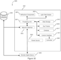
- a digital display device generally referred to using the numeral 100
- the device 100 is generally depicted as a smartphone or the like, though other devices encompassing a graphical display may equally be considered, such as tablets, e-readers, watches, televisions, GPS devices, laptops, desktop computer monitors, televisions, smart televisions, handheld video game consoles and controllers, vehicular dashboard and/or entertainment displays, and the like.
- the device 100 comprises a processing unit 110, a digital display 120, and internal memory 130.
- Display 120 can be an LCD screen, a monitor, a plasma display panel, an LED or OLED screen, or any other type of digital display defined by a set of pixels for rendering a pixelated image or other like media or information.
- Internal memory 130 can be any form of electronic storage, including a disk drive, optical drive, read-only memory, random-access memory, or flash memory, to name a few examples.
- memory 130 has stored in it vision correction application 140, though various methods and techniques may be implemented to provide computer-readable code and instructions for execution by the processing unit in order to process pixel data for an image to be rendered in producing corrected pixel data amenable to producing a corrected image accommodating the user's reduced visual acuity (e.g. stored and executable image correction application, tool, utility or engine, etc.).
- Other components of the electronic device 100 may optionally include, but are not limited to, one or more rear and/or front-facing camera(s) 150, an accelerometer 160 and/or other device positioning/orientation devices capable of determining the tilt and/or orientation of electronic device 100, and the like.
- the electronic device 100 may include further hardware, firmware and/or software components and/or modules to deliver complementary and/or cooperative features, functions and/or services.
- a pupil/eye tracking system may be integrally or cooperatively implemented to improve or enhance corrective image rending by tracking a location of the user's eye(s)/pupil(s) (e.g. both or one, e.g. dominant, eye(s)) and adjusting light field corrections accordingly.
- the device 100 may include, integrated therein or interfacing therewith, one or more eye/pupil tracking light sources, such as one or more infrared (IR) or near-IR (NIR) light source(s) to accommodate operation in limited ambient light conditions, leverage retinal retro-reflections, invoke corneal reflection, and/or other such considerations.
- eye/pupil tracking light sources such as one or more infrared (IR) or near-IR (NIR) light source(s) to accommodate operation in limited ambient light conditions, leverage retinal retro-reflections, invoke corneal reflection, and/or other such considerations.
- IR/NIR pupil tracking techniques may employ one or more (e.g. arrayed) directed or broad illumination light sources to stimulate retinal retro-reflection and/or corneal reflection in identifying a tracking a pupil location.
- Other techniques may employ ambient or IR/NIR light-based machine vision and facial recognition techniques to otherwise locate and track the user's eye(s)/pupil(s).
- one or more corresponding (e.g. visible, IR/NIR) cameras may be deployed to capture eye/pupil tracking signals that can be processed, using various image/sensor data processing techniques, to map a 3D location of the user's eye(s)/pupil(s).
- eye/pupil tracking hardware/software may be integral to the device, for instance, operating in concert with integrated components such as one or more front facing camera(s), onboard IR/NIR light source(s) and the like.
- eye/pupil tracking hardware may be further distributed within the environment, such as dash, console, ceiling, windshield, mirror or similarly-mounted camera(s), light sources, etc.
- the electronic device 100 is further shown to include a light field shaping layer (LFSL) 200 overlaid atop a display 120 thereof and spaced therefrom via a transparent spacer 310 or other such means as may be readily apparent to the skilled artisan.
- LFSL light field shaping layer
- An optional transparent screen protector 320 is also included atop the layer 200.
- a lenslet array comprising an array of microlenses (also interchangeably referred to herein as lenslets) that are each disposed at a distance from a corresponding subset of image rendering pixels in an underlying digital display.
- a light field shaping layer may be manufactured and disposed as a digital screen overlay, other integrated concepts may also be considered, for example, where light field shaping elements are integrally formed or manufactured within a digital screen's integral components such as a textured or masked glass plate, beam-shaping light sources (e.g. directional light sources and/or backlit integrated optical grating array) or like component.
- each lenslet will predictively shape light emanating from these pixel subsets to at least partially govern light rays being projected toward the user by the display device.
- other light field shaping layers may also be considered herein without departing from the scope of the present disclosure, whereby light field shaping will be understood by the person of ordinary skill in the art to reference measures by which light, that would otherwise emanate indiscriminately (i.e. isotropically) from each pixel group, is deliberately controlled to define predictable light rays that can be traced between the user and the device's pixels through the shaping layer.
- a light field is generally defined as a vector function that describes the amount of light flowing in every direction through every point in space.
- anything that produces or reflects light has an associated light field.
- the embodiments described herein produce light fields from an object that are not "natural” vector functions one would expect to observe from that object. This gives it the ability to emulate the "natural" light fields of objects that do not physically exist, such as a virtual display located far behind the light field display, which will be referred to now as the ⁇ virtual image'.
- light field rendering may be adjusted to effectively generate a virtual image on a virtual image plane that is set at a designated distance from an input user pupil location, for example, so to effective push back, or move forward, a perceived image relative to the display device in accommodating a user's reduced visual acuity (e.g. minimum or maximum viewing distance).
- light field rendering may rather or alternatively seek to map the input image on a retinal plane of the user, taking into account visual aberrations, so to adaptively adjust rendering of the input image on the display device to produce the mapped effect.
- the unadjusted input image would otherwise typically come into focus in front of or behind the retinal plane (and/or be subject to other optical aberrations)
- this approach allows to map the intended image on the retinal plane and work therefrom to address designated optical aberrations accordingly.
- the device may further computationally interpret and compute virtual image distances tending toward infinity, for example, for extreme cases of presbyopia.
- This approach may also more readily allow, as will be appreciated by the below description, for adaptability to other visual aberrations that may not be as readily modeled using a virtual image and image plane implementation.
- the input image is digitally mapped to an adjusted image plane (e.g. virtual image plane or retinal plane) designated to provide the user with a designated image perception adjustment that at least partially addresses designated visual aberrations.
- an adjusted image plane e.g. virtual image plane or retinal plane
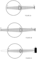
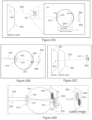
- a light field display projects the correct sharp image (H) on the retina for an eye with a crystalline lens which otherwise could not accommodate sufficiently to produce a sharp image.
- the other two light field pixels (I) and (J) are drawn lightly, but would otherwise fill out the rest of the image.
- a light field as seen in Figure 3C cannot be produced with a 'normal' two-dimensional display because the pixels' light field emits light isotropically. Instead it is necessary to exercise tight control on the angle and origin of the light emitted, for example, using a microlens array or other light field shaping layer such as a parallax barrier, or combination thereof.
- Figure 4 schematically illustrates a single light field pixel defined by a convex microlens (B) disposed at its focus from a corresponding subset of pixels in an LCD display (C) to produce a substantially collimated beam of light emitted by these pixels, whereby the direction of the beam is controlled by the location of the pixel(s) relative to the microlens.
- the single light field pixel produces a beam similar to that shown in Figure 3C where the outside rays are lighter and the majority inside rays are darker.
- the LCD display (C) emits light which hits the microlens (B) and it results in a beam of substantially collimated light (A).
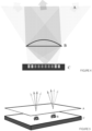
- FIG. 5 schematically illustrates an example of a light field display assembly in which a microlens array (A) sits above an LCD display on a cellphone (C) to have pixels (B) emit light through the microlens array.
- a ray-tracing algorithm can thus be used to produce a pattern to be displayed on the pixel array below the microlens in order to create the desired virtual image that will effectively correct for the viewer's reduced visual acuity.
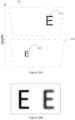
- Figure 6 provides an example of such a pattern for the letter "Z”. Examples of such ray-tracing algorithms are discussed below.
- the separation between the microlens array and the pixel array as well as the pitch of the lenses can be selected as a function of various operating characteristics, such as the normal or average operating distance of the display, and/or normal or average operating ambient light levels.
- a correct light field can be produced, in some embodiments, only at or around the location of the user's pupils.
- the light field display can be paired with pupil tracking technology to track a location of the user's eyes/pupils relative to the display. The display can then compensate for the user's eye location and produce the correct virtual image, for example, in real time.
- the light field display can render dynamic images at over 30 frames per second on the hardware in a smartphone.
- the light field display can display a virtual image at optical infinity, meaning that any level of accommodation-based presbyopia (e.g. first order) can be corrected for.
- any level of accommodation-based presbyopia e.g. first order
- the light field display can both push the image back or forward, thus allowing for selective image corrections for both hyperopia (farsightedness) and myopia (nearsightedness).
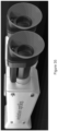
- a camera was equipped with a simple lens, to simulate the lens in a human eye and the aperture was set to simulate a normal pupil diameter.
- the lens was focused to 50cm away and a phone was mounted 25cm away. This would approximate a user whose minimal seeing distance is 50 cm and is attempting to use a phone at 25cm.
- Figures 9A and 9B provide another example of results achieved using an exemplary embodiment, in which a colour image was displayed on the LCD display of a Sony TM Xperia TM XZ Premium phone (reported screen resolution of 3840x2160 pixels with 16:9 ratio and approximately 807 pixel-per-inch (ppi) density) without image correction ( Figure 9A ) and with image correction through a square fused silica microlens array set at a 2 degree angle relative to the screen's square pixel array and defined by microlenses having a 7.0mm focus and 200 ⁇ m pitch.
- the camera lens was again focused at 50cm with the phone positioned 30cm away.
- Another microlens array was used to produce similar results, and consisted of microlenses having a 10.0mm focus and 150 ⁇ m pitch.
- Figures 10A and 10B provide yet another example or results achieved using an exemplary embodiment, in which a colour image was displayed on the LCD display of the Sony TM Xperia TM XZ Premium phone without image correction ( Figure 10A ) and with image correction through a square fused silica microlens array set at a 2 degree angle relative to the screen's square pixel array and defined by microlenses having a 10.0mm focus and 150 ⁇ m pitch.
- the camera lens was focused at 66cm with the phone positioned 40cm away.
- a display device as described above and further exemplified below, can be configured to render a corrected image via the light field shaping layer that accommodates for the user's visual acuity.
- the image correction in accordance with the user's actual predefined, set or selected visual acuity level, different users and visual acuity may be accommodated using a same device configuration. That is, in one example, by adjusting corrective image pixel data to dynamically adjust a virtual image distance below/above the display as rendered via the light field shaping layer, different visual acuity levels may be accommodated.
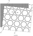
- the microlens array 800 is defined by a hexagonal array of microlenses 802 disposed so to overlay a corresponding square pixel array 804.
- each microlens 802 can be aligned with a designated subset of pixels to produce light field pixels as described above, the hexagonal-to-square array mismatch can alleviate certain periodic optical artifacts that may otherwise be manifested given the periodic nature of the optical elements and principles being relied upon to produce the desired optical image corrections.
- a square microlens array may be favoured when operating a digital display comprising a hexagonal pixel array.
- the microlens array 800 may further or alternatively overlaid at an angle 806 relative to the underlying pixel array, which can further or alternatively alleviate period optical artifacts.
- a pitch ratio between the microlens array and pixel array may be deliberately selected to further or alternatively alleviate periodic optical artifacts.
- a perfectly matched pitch ratio i.e. an exact integer number of display pixels per microlens
- the pitch ratio will be selected to define an irrational number, or at least, an irregular ratio, so to minimize periodic optical artifacts.
- a structural periodicity can be defined so to reduce the number of periodic occurrences within the dimensions of the display screen at hand, e.g. ideally selected so to define a structural period that is greater than the size of the display screen being used.
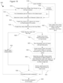
- an exemplary computationally implemented ray-tracing method for rendering an adjusted image via an array of light field shaping elements in this example provided by a light field shaping layer (LFSL) disposed relative to a set of underlying display pixels, that accommodates for the user's reduced visual acuity
- LFSL light field shaping layer
- a set of constant parameters 1102 may be pre-determined. These may include, for example, any data that are not expected to significantly change during a user's viewing session, for instance, which are generally based on the physical and functional characteristics of the display for which the method is to be implemented, as will be explained below. Similarly, every iteration of the rendering algorithm may use a set of input variables 1104 which are expected to change either at each rendering iteration or at least between each user's viewing session.
- the list of constant parameters 1102 may include, without limitations, the distance 1204 between the display and the LFSL, the in-plane rotation angle 1206 between the display and LFSL frames of reference, the display resolution 1208, the size of each individual pixel 1210, the optical LFSL geometry 1212, the size of each optical element 1214 within the LFSL and optionally the subpixel layout 1216 of the display.
- both the display resolution 1208 and the size of each individual pixel 1210 may be used to pre-determine both the absolute size of the display in real units (i.e. in mm) and the three-dimensional position of each pixel within the display.
- the position within the display of each subpixel may also be pre-determined.
- These three-dimensional location/positions are usually calculated using a given frame of reference located somewhere within the plane of the display, for example a corner or the middle of the display, although other reference points may be chosen.
- Concerning the optical layer geometry 1212 different geometries may be considered, for example a hexagonal geometry such as the one shown in Figure 8 .
- the distance 1204, the rotation angle 1206, and the geometry 1212 with the optical element size 1214 it is possible to similarly pre-determine the three-dimensional location/position of each optical element center with respect to the display's same frame of reference.
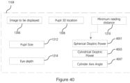
- Figure 13 meanwhile illustratively lists an exemplary set of input variables 1104 for method 1100, which may include any input data fed into method 1100 that may reasonably change during a user's single viewing session, and may thus include without limitation: the image(s) to be displayed 1306 (e.g. pixel data such as on/off, colour, brightness, etc.), the three-dimensional pupil location 1308 (e.g. in embodiments implementing active eye/pupil tracking methods) and/or pupil size 1312 and the minimum reading distance 1310 (e.g. one or more parameters representative of the user's reduced visual acuity or condition).
- the eye depth 1314 may also be used.
- the image data 1306, for example, may be representative of one or more digital images to be displayed with the digital pixel display.
- This image may generally be encoded in any data format used to store digital images known in the art.
- images 1306 to be displayed may change at a given framerate.
- the pupil location 1308, in one embodiment, is the three-dimensional coordinates of at least one the user's pupils' center with respect to a given reference frame, for example a point on the device or display.
- This pupil location 1308 may be derived from any eye/pupil tracking method known in the art.
- the pupil location 1308 may be determined prior to any new iteration of the rendering algorithm, or in other cases, at a lower framerate.
- only the pupil location of a single user's eye may be determined, for example the user's dominant eye (i.e. the one that is primarily relied upon by the user).
- this position, and particularly the pupil distance to the screen may otherwise or additionally be rather approximated or adjusted based on other contextual or environmental parameters, such as an average or preset user distance to the screen (e.g. typical reading distance for a given user or group of users; stored, set or adjustable driver distance in a vehicular environment; etc.).
- an average or preset user distance to the screen e.g. typical reading distance for a given user or group of users; stored, set or adjustable driver distance in a vehicular environment; etc.
- the minimum reading distance 1310 is defined as the minimal focus distance for reading that the user's eye(s) may be able to accommodate (i.e. able to view without discomfort).
- different values of the minimum reading distance 1310 associated with different users may be entered, for example, as can other adaptive vision correction parameters be considered depending on the application at hand and vision correction being addressed.
- minimum reading distance 1310 may be derived from an eye prescription (e.g. glasses prescription or contact prescription) or similar. It may, for example, correspond to the near point distance corresponding to the uncorrected user's eye, which can be calculated from the prescribed corrective lens power assuming that the targeted near point was at 25 cm.
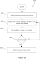
- step 1106 in which the minimum reading distance 1310 (and/or related parameters) is used to compute the position of a virtual (adjusted) image plane 1405 with respect to the device's display, followed by step 1108 wherein the size of image 1306 is scaled within the image plane 1405 to ensure that it correctly fills the pixel display 1401 when viewed by the distant user.
- Figure 14A shows a diagram of the relative positioning of the user's pupil 1415, the light field shaping layer 1403, the pixel display 1401 and the virtual image plane 1405.
- the size of image 1306 in image plane 1405 is increased to avoid having the image as perceived by the user appear smaller than the display's size.
- steps 1110 to 1128 of Figure 11 At the end of which the output color of each pixel of pixel display 1401 is known so as to virtually reproduce the light field emanating from an image 1306 positioned at the virtual image plane 1405.
- steps 1110 to 1126 describes the computations done for each individual pixel.
- steps 1110 to 1128 may executed in parallel for each pixel or a subset of pixels at the same time.
- this exemplary method is well suited to vectorization and implementation on highly parallel processing architectures such as GPUs.
- step 1110 for a given pixel 1409 in pixel display 1401, a trial vector 1413 is first generated from the pixel's position to the center position 1417 of pupil 1415. This is followed in step 1112 by calculating the intersection point 1411 of vector 1413 with the LFSL 1403.
- step 1114 finds, in step 1114, the coordinates of the center 1416 of the LFSL optical element closest to intersection point 1411. This step may be computationally intensive and will be discussed in more depth below.
- a normalized unit ray vector is generated from drawing and normalizing a vector 1423 drawn from center position 1416 to pixel 1409. This unit ray vector generally approximates the direction of the light field emanating from pixel 1409 through this particular light field element, for instance, when considering a parallax barrier aperture or lenslet array (i.e. where the path of light travelling through the center of a given lenslet is not deviated by this lenslet).
- this ray vector will be used to find the portion of image 1306, and thus the associated color, represented by pixel 1409. But first, in step 1118, this ray vector is projected backwards to the plane of pupil 1415, and then in step 1120, the method verifies that the projected ray vector 1425 is still within pupil 1415 (i.e. that the user can still "see” it).
- the distance between the pupil center 1417 and the intersection point 1431 may be calculated to determine if the deviation is acceptable, for example by using a pre-determined pupil size and verifying how far the projected ray vector is from the pupil center.
- step 1122 the method flags pixel 1409 as unnecessary and to simply be turned off or render a black color. Otherwise, as shown in Figure 14C , in step 1124, the ray vector is projected once more towards virtual image plane 1405 to find the position of the intersection point 1423 on image 1306. Then in step 1126, pixel 1409 is flagged as having the color value associated with the portion of image 1306 at intersection point 1423.
- method 1100 is modified so that at step 1120, instead of having a binary choice between the ray vector hitting the pupil or not, one or more smooth interpolation function (i.e. linear interpolation, Hermite interpolation or similar) are used to quantify how far or how close the intersection point 1431 is to the pupil center 1417 by outputting a corresponding continuous value between 1 or 0.
- the assigned value is equal to 1 substantially close to pupil center 1417 and gradually change to 0 as the intersection point 1431 substantially approaches the pupil edges or beyond.
- the branch containing step 1122 is ignored and step 1220 continues to step 1124.
- the pixel color value assigned to pixel 1409 is chosen to be somewhere between the full color value of the portion of image 1306 at intersection point 1423 or black, depending on the value of the interpolation function used at step 1120 (1 or 0).
- pixels found to illuminate a designated area around the pupil may still be rendered, for example, to produce a buffer zone to accommodate small movements in pupil location, for example, or again, to address potential inaccuracies, misalignments or to create a better user experience.
- steps 1118, 1120 and 1122 may be avoided completely, the method instead going directly from step 1116 to step 1124.
- no check is made that the ray vector hits the pupil or not, but instead the method assumes that it always does.
- step 1130 the output colors of all pixels have been determined, these are finally rendered in step 1130 by pixel display 1401 to be viewed by the user, therefore presenting a light field corrected image.
- the method may stop here.
- new input variables may be entered and the image may be refreshed at any desired frequency, for example because the user's pupil moves as a function of time and/or because instead of a single image a series of images are displayed at a given framerate.
- a set of constant parameters 1102 may also be pre-determined. These may include, for example, any data that are not expected to significantly change during a user's viewing session, for instance, which are generally based on the physical and functional characteristics of the display for which the method is to be implemented, as will be explained below.
- every iteration of the rendering algorithm may use a set of input variables 1104 which are expected to change either at each rendering iteration or at least between each user viewing session.
- the list of possible variables and constants is substantially the same as the one disclosed in Figures 12 and 13 and will thus not be replicated here.
- this second exemplary ray-tracing methodology proceeds from steps 1910 to 1936, at the end of which the output color of each pixel of the pixel display is known so as to virtually reproduce the light field emanating from an image perceived to be positioned at the correct or adjusted image distance, in one example, so to allow the user to properly focus on this adjusted image (i.e. having a focused image projected on the user's retina) despite a quantified visual aberration.
- steps 1910 to 1936 are illustrated in a loop over each pixel in pixel display 1401, so that each of steps 1910 to 1934 describes the computations done for each individual pixel.
- these computations need not be executed sequentially, but rather, steps 1910 to 1934 may be executed in parallel for each pixel or a subset of pixels at the same time.
- this second exemplary method is also well suited to vectorization and implementation on highly parallel processing architectures such as GPUs.
- step 1910 for a given pixel in pixel display 1401, a trial vector 1413 is first generated from the pixel's position to pupil center 1417 of the user's pupil 1415. This is followed in step 1912 by calculating the intersection point of vector 1413 with optical layer 1403.
- step 1914 the coordinates of the optical element center 1416 closest to intersection point 1411 are determined. This step may be computationally intensive and will be discussed in more depth below.
- a normalized unit ray vector is generated from drawing and normalizing a vector 1423 drawn from optical element center 1416 to pixel 1409. This unit ray vector generally approximates the direction of the light field emanating from pixel 1409 through this particular light field element, for instance, when considering a parallax barrier aperture or lenslet array (i.e. where the path of light travelling through the center of a given lenslet is not deviated by this lenslet).
- this ray vector is projected backwards to pupil 1415, and then in step 1920, the method ensures that the projected ray vector 1425 is still within pupil 1415 (i.e. that the user can still "see” it).
- the distance between the pupil center 1417 and the intersection point 1431 may be calculated to determine if the deviation is acceptable, for example by using a pre-determined pupil size and verifying how far the projected ray vector is from the pupil center.
- steps 1921 to 1929 of method 1900 will be described.
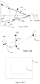
- a vector 2004 is drawn from optical element center 1416 to pupil center 1417.
- vector 2004 is projected further behind the pupil plane onto eye focal plane 2006 (location where any light rays originating from optical layer 1403 would be focused by the eye) to locate focal point 2008.
- eye focal plane 2006 location where any light rays originating from optical layer 1403 would be focused by the eye
- focal plane 2006 would be located at the same location as retina plane 2010, but in this example, focal plane 2006 is located behind retina plane 2010, which would be expected for a user with some form of farsightedness.
- the position of focal plane 2006 may be derived from the user's minimum reading distance 1310, for example, by deriving therefrom the focal length of the user's eye.
- Other manually input or computationally or dynamically adjustable means may also or alternatively be considered to quantify this parameter.
- any light ray originating from optical element center 1416, no matter its orientation, will also be focused onto focal point 2008, to a first approximation. Therefore, the location 2012 on retina plane 2010 onto which light entering the pupil at intersection point 1431 will converge may be approximated by drawing a straight line between intersection point 1431 where ray vector 1425 hits the pupil 1415 and focal point 2008 on focal plane 2006.
- the intersection of this line with retina plane 2010 is thus the location on the user's retina corresponding to the image portion that will be reproduced by corresponding pixel 1409 as perceived by the user. Therefore, by comparing the relative position of retina point 2012 with the overall position of the projected image on the retina plane 2010, the relevant adjusted image portion associated with pixel 1409 may be computed.
- step 1927 the corresponding projected image center position on retina plane 2010 is calculated.
- Vector 2016 is generated originating from the center position of display 1401 (display center position 2018) and passing through pupil center 1417.
- Vector 2016 is projected beyond the pupil plane onto retina plane 2010, wherein the associated intersection point gives the location of the corresponding retina image center 2020 on retina plane 2010.
- step 1927 could be performed at any moment prior to step 1929, once the relative pupil center location 1417 is known in input variables step 1904.
- image center 2020 Once image center 2020 is known, one can then find the corresponding image portion of the selected pixel/subpixel at step 1929 by calculating the x/y coordinates of retina image point 2012 relative to retina image center 2020 on the retina, scaled to the x/y retina image size 2031.
- This retina image size 2031 may be computed by calculating the magnification of an individual pixel on retina plane 2010, for example, which may be approximately equal to the x or y dimension of an individual pixel multiplied by the eye depth 1314 and divided by the absolute value of the distance to the eye (i.e. the magnification of pixel image size from the eye lens).
- the input image is also scaled by the image x/y dimensions to produce a corresponding scaled input image 2064.
- Both the scaled input image and scaled retina image should have a width and height between -0.5 to 0.5 units, enabling a direct comparison between a point on the scaled retina image 2010 and the corresponding scaled input image 2064, as shown in Figure 20D .
- the image portion position 2041 relative to retina image center position 2043 in the scaled coordinates corresponds to the inverse (because the image on the retina is inverted) scaled coordinates of retina image point 2012 with respect to retina image center 2020.
- the associated color with image portion position 2041 is therefrom extracted and associated with pixel 1409.
- method 1900 may be modified so that at step 1920, instead of having a binary choice between the ray vector hitting the pupil or not, one or more smooth interpolation function (i.e. linear interpolation, Hermite interpolation or similar) are used to quantify how far or how close the intersection point 1431 is to the pupil center 1417 by outputting a corresponding continuous value between 1 or 0.
- the assigned value is equal to 1 substantially close to pupil center 1417 and gradually change to 0 as the intersection point 1431 substantially approaches the pupil edges or beyond.
- the branch containing step 1122 is ignored and step 1920 continues to step 1124.
- the pixel color value assigned to pixel 1409 is chosen to be somewhere between the full color value of the portion of image 1306 at intersection point 1423 or black, depending on the value of the interpolation function used at step 1920 (1 or 0).
- pixels found to illuminate a designated area around the pupil may still be rendered, for example, to produce a buffer zone to accommodate small movements in pupil location, for example, or again, to address potential inaccuracies or misalignments.
- step 1934 the output colors of all pixels in the display have been determined (check at step 1934 is true), these are finally rendered in step 1936 by pixel display 1401 to be viewed by the user, therefore presenting a light field corrected image.
- the method may stop here.
- new input variables may be entered and the image may be refreshed at any desired frequency, for example because the user's pupil moves as a function of time and/or because instead of a single image a series of images are displayed at a given framerate.
- mapping the input image to a virtual image plane set at a designated minimum (or maximum) comfortable viewing distance can provide one solution
- the alternate solution may allow accommodation of different or possibly more extreme visual aberrations. For example, where a virtual image is ideally pushed to infinity (or effectively so), computation of an infinite distance becomes problematic.
- the illustrative process of Figure 19 can accommodate the formation of a virtual image effectively set at infinity without invoking such computational challenges.
- first order aberrations are illustratively described with reference to Figure 19
- higher order or other optical anomalies may be considered within the present context, whereby a desired retinal image is mapped out and traced while accounting for the user's optical aberration(s) so to compute adjusted pixel data to be rendered in producing that image.
- each core is dedicated to a small neighborhood of pixel values within an image, e.g., to perform processing that applies a visual effect, such as shading, fog, affine transformation, etc.
- GPUs are usually also optimized to accelerate exchange of image data between such processing cores and associated memory, such as RGB frame buffers.
- smartphones are increasingly being equipped with powerful GPUs to speed the rendering of complex screen displays, e.g., for gaming, video, and other image-intensive applications.
- Several programming frameworks and languages tailored for programming on GPUs include, but are not limited to, CUDA, OpenCL, OpenGL Shader Language (GLSL), High-Level Shader Language (HLSL) or similar.
- GLSL OpenGL Shader Language
- HLSL High-Level Shader Language
- step 1114 of Figure 11 is expanded to include steps 1515 to 1525.
- the method receives from step 1112 the 2D coordinates of the intersection point 1411 (illustrated in Figure 14A ) of the trial vector 1413 with optical layer 1403.
- step 1515 these input intersection coordinates, which are initially calculated from the display's frame of reference, may first be rotated to be expressed from the light field shaping layer's frame of reference and optionally normalized so that each individual light shaping element has a width and height of 1 unit.
- the following description will be equally applicable to any light field shaping layer having a hexagonal geometry like the exemplary embodiment of Figure 8 . Note however that the method steps 1515 to 1525 described herein may be equally applied to any kind of light field shaping layer sharing the same geometry (i.e. not only a microlens array, but pinhole arrays as well, etc.).
- hexagonal LFSL element arrays such as stretched/elongated, skewed and/or rotated arrays may be considered, as can other nestled array geometries in which adjacent rows and/or columns of the LFSL array at least partially "overlap" or inter-nest.
- hexagonal arrays and like nestled array geometries will generally provide for a commensurately sized rectangular/square tile of an overlaid rectangular/square array or grid to naturally encompass distinct regions as defined by two or more adjacent underlying nestled array tiles, which can be used to advantage in the examples provided below.
- the processes discussed herein may be applied to rectangular and/or square LFSL element arrays.
- Other LFSL element array geometries may also be considered, as will be appreciated by the skilled artisan upon reading of the following example, without departing from the scope of the present disclosure.
- the hexagonal symmetry of the light field shaping layer 1403 may be represented by drawing an array of hexagonal tiles 1601, each centered on their respective light field shaping element, so that the center of a hexagonal tile element is more or less exactly the same as the center position of its associated light field shaping element.
- the original problem is translated to a slightly similar one whereby one now needs to find the center position 1615 of the associated hexagonal tile 1609 closest to the intersection point 1411, as shown in Figure 16B .
- the array of hexagonal tiles 1601 may be superimposed on or by a second array of staggered rectangular tiles 1705, in such a way as to make an "inverted house" diagram within each rectangle, as clearly illustrated in Figure 17A , namely defining three linearly segregated tile regions for each rectangular tile, one region predominantly associated with a main underlying hexagonal tile, and two other opposed triangular regions associated with adjacent underlying hexagonal tiles.
- the nestled hexagonal tile geometry is translated to a rectangular tile geometry having distinct linearly segregated tile regions defined therein by the edges of underlying adjacently disposed hexagonal tiles.
- boundary types may also be considered provided they are amenable to the definition of one or more conditional statements, as illustrated below, that can be used to output a corresponding set of binary or Boolean values that distinctly identify a location of a given point within one or another of these regions, for instance, without invoking, or by limiting, processing demands common to branching or looping decision logics/trees/statements/etc.
- each region is associated with a different hexagonal tile, as shown in Figure 18A , namely, each region is delineated by the linear boundaries of adjacent underlying hexagonal tiles to define one region predominantly associated with a main hexagonal tile, and two opposed triangular tiles defined by adjacent hexagonal tiles on either side of this main tile.
- the possible x and y values of the position of intersection point 1411 within associated rectangular tile 1814 are now contained within -1 ⁇ x ⁇ 1 and 0 ⁇ y ⁇ 3. This will make the next step easier to compute.
- each region is separated by a diagonal line.
- a diagonal line 1855 which in the rescaled coordinates of Figure 18B .
- step 1521 the associated region containing the intersection point is evaluated by using these two simple conditional statements.
- the resulting set of two Boolean values will thus be specific to the region where the intersection point is located.
- One may then convert these Boolean values to floating points values, wherein usually in most programming languages true/false Boolean values are converted into 1.0/0.0 floating point values.
- the set (caseL, caseR) of values of (1.0, 0.0), (0.0, 1.0) or (0.0, 0.0) for each of the described regions above.
- the set of converted Boolean values may be used as an input to a single floating point vectorial function operable to map each set of these values to a set of xy coordinates of the associated element center.
- step 1525 we may proceed with the final step 1525 to translate the relative coordinates obtained above to absolute 3D coordinates with respect to the display or similar (i.e. in mm).
- the coordinates of the hexagonal tile center and the coordinates of the bottom left corner are added to get the position of the hexagonal tile center in the optical layer's frame of reference.
- the process may then scale back the values into absolute units (i.e. mm) and rotate the coordinates back to the original frame of reference with respect to the display to obtain the 3D positions (in mm) of the optical layer element's center with respect to the display's frame of reference, which is then fed into step 1116.
- a slightly different method may be used to identify the associated LFSL element (microlens) center (step 1114).
- the microlens array is represented by an array of rectangular and/or square tiles. The method, as previously described, goes through step 1515, where the x and y coordinates are rescaled (normalized) with respect to a microlens x and y dimension (henceforth giving each rectangular and/or square tile a width and height of 1 unit).
- step 1525 the coordinates are scaled back into absolute units (i.e. mm) and rotated back to the original frame of reference with respect to the display to obtain the 3D positions (in mm) of the optical layer element's center with respect to the display's frame of reference, which is then fed into step 1116.
- the light field rendering methods described above may also be applied, in some embodiments, at a subpixel level in order to achieve an improved light field image resolution.
- a single pixel on a color subpixelated display is typically made of several color primaries, typically three colored elements - ordered (on various displays) either as blue, green and red (BGR) or as red, green and blue (RGB).
- BGR blue, green and red
- RGBY red, green, blue and white
- RGBYC red, green, blue, yellow and cyan
- Subpixel rendering operates by using the subpixels as approximately equal brightness pixels perceived by the luminance channel.
- an exemplary pixel 2115 is comprised of three RBG subpixels (2130 for red, 2133 for green and 2135 for blue). Other embodiments may deviate from this color partitioning, without limitation.
- the image portion 2145 associated with said pixel 2115 is sampled to extract the luminance value of each RGB color channels 2157, which are then all rendered by the pixel at the same time.
- the methods find the image portion 2147 associated with blue subpixel 2135. Therefore, only the subpixel channel intensity value of RGB color channels 2157 corresponding to the target subpixel 2135 is used when rendering (herein the blue subpixel color value, the other two values are discarded).
- a higher adjusted image resolution may be achieved for instance, by adjusting adjusted image pixel colours on a subpixel basis, and also optionally discarding or reducing an impact of subpixels deemed not to intersect or to only marginally intersect with the user's pupil.
- a (LCD) pixel array 2200 is schematically illustrated to be composed of an array of display pixels 2202 each comprising red (R) 2204, green (G) 2206, and blue (B) 2208 subpixels.
- a light field shaping layer such as a microlens array, is to be aligned to overlay these pixels such that a corresponding subset of these pixels can be used to predictably produce respective light field rays to be computed and adjusted in providing a corrected image.
- the light field ray ultimately produced by each pixel can be calculated knowing a location of the pixel (e.g.
- the image correction algorithm will compute which pixels to light and how, and output subpixel lighting parameters (e.g. R, G and B values) accordingly.
- subpixel lighting parameters e.g. R, G and B values
- an angular edge 2209 is being rendered that crosses the surfaces of affected pixels 2210, 2212, 2214 and 2216.
- each affected pixel is either turned on or off, which to some extent dictates a relative smoothness of the angular edge 2209.
- subpixel rendering is instead favoured, whereby the red subpixel in pixel 2210, the red and green subpixels in pixel 2214 and the red subpixel in pixel 2216 are deliberately set to zero (0) to produce a smoother representation of the angular edge 2209 at the expense of colour trueness along that edge, which will not be perceptible to the human eye given the scale at which these modifications are being applied. Accordingly, image correction can benefit from greater subpixel control while delivering sharper images.
- ray tracing calculations must be executed in respect of each subpixel, as opposed to in respect of each pixel as a whole, based on a location (x,y coordinates on the screen) of each subpixel.
- subpixel control and ray tracing computations may accommodate different subpixel configurations, for example, where subpixel mixing or overlap is invoked to increase a perceived resolution of a high resolution screen and/or where nonuniform subpixel arrangements are provided or relied upon in different digital display technologies.
- a given pixel 2300 is shown to include horizontally distributed red (R) 2304, green (G) 2306, and blue (B) 2308 subpixels.
- R red
- G green
- B blue
- ray tracing could otherwise be calculated in triplicate by specifically addressing the geometric location of each subpixel. Knowing the distribution of subpixels within each pixel, however, calculations can be simplified by maintaining pixel-centered computations and applying appropriate offsets given known geometric subpixel offsets (i.e. negative horizontal offset 2314 for the red subpixel 2304, a zero offset for the green 2306 and a positive horizontal offset 2318 for the blue subpixel 2308). In doing so, light field image correction can still benefit from subpixel processing without significantly increased computation load.
- known geometric subpixel offsets i.e. negative horizontal offset 2314 for the red subpixel 2304, a zero offset for the green 2306 and a positive horizontal offset 2318 for the blue subpixel 2308.
- texture caches are designed for graphics applications where memory access patterns exhibit a great deal of spatial locality, which is the case of the steps 1110-1126 of method 1100.
- image 1306 may be stored inside the texture memory of the GPU, which then greatly improves the retrieval speed during step 1126 where the color channel associated with the portion of image 1306 at intersection point 1423 is determined.
- FIG. 39A to 39C and Figures 20A to 20D the different planes illustrated (e.g. pixel display 1401, optical layer 1405, pupil plane 1415, virtual image plane 1405, retina plane 2010 and focal plane 2006) were all shown as being parallel to one another to better describe the ray-tracing methodology associated therewith.
- the corresponding ray-tracing methods 1100 of Figures 11 and 1900 of Figure 19 may also be applied to account for changes in the relative orientation between any one of those planes.
- cases may be considered wherein the user is viewing the light field display at an angle.
- the ray-tracing method can therefore account for a change in orientation of the pupil plane 1415 with respect to the pixel display 1401 and optical layer 1405.
- other planes such as virtual image plane 1405 (used in the ray-tracing method of Figure 11 ), and retina plane 2010 and focal plane 2006 (used in the ray-tracing method of Figure 19 ) may be taken to be parallel to pupil plane 1415.
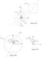
- the relative difference in orientation between the two sets of planes is illustrated by using vector 3850 which is the normal vector to the plane of corresponding optical layer 1403, and vector 3870 which is the normal vector to pupil plane 1415.
- the relative orientation between the two normal vectors is illustrated in Figure 38B , using polar and azimuthal angles.
- the general orientation of pupil plane 1415 may be parametrized, for example, by using the 3D location of pupil center 1417 and a corresponding normal vector 1415.
- Normal vector 1415 may be taken to be, in some embodiments, equal to the gaze direction as measured by a gaze tracking system or similar, as will be discussed below.
- the relative position/orientation of all remaining planes may be determined and parametrized accordingly. Planes that are parallel share the same normal vector. From there, the methods of Figures 11 and 19 can be applied by finding the intersection point between an arbitrary vector and an arbitrarily oriented plane, as is done for example at steps 1112, 1118, 1124 of the method of Figure 11 , and steps 1912, 1918, 1923, 1925 of the method of Figure 19 .
- the position of virtual image plane 1405 may be computed using the minimum reading distance 1310 (and/or related parameters) but from the position of pupil plane 1415 and along the direction vector 3870.
- pupil plane 1415 may be re-parametrized using an updated 3D location of pupil center 1417 and an updated normal vector 3870 at each eye tracking cycle.
- a hybrid gaze tracking/pupil tracking system or method may be used wherein gaze direction (e.g.
- normal vector 3870 is provided at a different interval than pupil center location 1417.
- pupil center location 1417 For example, in some embodiments, for one or more cycles, only the 3D pupil center location 1417 may be measured and an old gaze direction vector may be re-used or manually updated.
- an eye model or similar may be constructed to map a change in measured pupil center location 1417 to a change in the gaze direction vector without relying on the full capabilities of the gaze tracking system or method. Such a map may be based on one or more previous gaze tracking measurements. In any case, by measuring/determining the 3D pupil center location 1417 and normal vector 3870, the pupil plane may be parametrized accordingly.
- display 1401 and optical layer 1403 are shown parallel for simplicity, but other embodiments may envision optical layer 1403 to be non-parallel to display 1401 as well. This doesn't change the general scope of the present discussion, as long as the relative angle between them is known. For example, such an angle may be pre-determined during manufacturing or measured in real-time using one or more sensors (for example in the case where optical layer 1403 may be mobile). Similarly, other planes like for example retina plane 2010 may also be made to be non-parallel to the pupil plane, depending on the user's eye geometry.
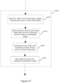
- step 4701 which may be used to replace the image scaling step on a virtual image plane, described above for example in steps 1106 and 1108 of methods 1100, and in accordance with one embodiment, will now be described.
- steps 1106 and 1108 or any step which requires to map and scale an image on a virtual plane
- step 4701 may be decomposed into a number of substeps 4721-4751.
- the relative orientation of the virtual image plane 1405 with respect to the light field display may be computed by drawing vectors from pupil center 1417 towards the corners of the light field display (for example the corner locations of pixel display 1401).
- Figures 39A and 39B which mirrors the schematic diagram of Figure 38A , the user's pupil is located off-axis and will thus be viewing the display at an angle.
- pupil center 1417 is always orientated towards display center location 2018
- the position and orientation of virtual image plane 1405 may be derived.
- four vectors may be drawn, each from pupil center 1417 towards a distinct corner of pixel display 1401.
- the corresponding intersection points of these vectors with virtual image plane 1405 will define a convex quadrilateral area 3903 on plane 1405 which is the area onto which the image must be drawn or mapped (in final step 4751) so to fill the display when viewed by user.
- the four vectors may be averaged and normalized, thus giving a normal vector 3901 which indicates the relative orientation of plane 1405.
- Figures 39A and 39B where we see four vectors originating from pupil center location 1417, each projected towards a corner of the display (points 3905, 3915, 3925 and 3935), which intersect with virtual image plane 1405 to define quadrilateral area 3903.
- Figure 39B shows a side view of the schematic diagram of Figure 39A while Figure 39C shows convex quadrilateral area 3903 from Figure 39A from the front.
- non-parallel configurations may require additional treatment when scaling the image on the virtual image plane 1405 so to fill the entire light field display when viewed by the user.
- non-parallel planes resulting from an off-axis pupil center position 1417 may require that the image be processed or converted to fit onto non-rectangular area 3903.
- different texture mapping and interpolation techniques may be used to deform or stretch an image texture onto non-rectangular shape 3903. For example, and without limitation, these may include bilinear interpolation.
- an exemplary computationally implemented ray-tracing method for rendering multiple images or image portions on multiple adjusted distinct image planes simultaneously via an array of light field shaping elements, or light field shaping layer (LFSL) thereof, will now be described.
- the previous above-described embodiments were directed to correcting a single image by directly or indirectly modifying the location of the virtual image plane and/or eye focal plane.
- the below-described embodiments are directed to a light field display which is generally operable to display multiple image planes at different locations/depths simultaneously. This enables a user to focus on each plane individually, thus creating a 2.5D effect.
- a portion of an image may mask or obscure a portion of another image located behind it depending on the location of the user's pupil (e.g. on an image plane perceived to be located at an increased distance from the display than the one of the first image portion).
- Other effects may include parallax motion between each image plane when the user moves.
- Method 2400 of Figure 24 substantially mirrors method 1100 of Figure 11 , but generalizes it to include multiple distinct virtual image planes. Thus, new steps 2406, 2408, and 2435 have been added, while steps 1110 to 1122, and 1126 to 1130 are the same as already described above.
- image data 1306 of input variables 1104 may also include depth information.
- any image or image portion may have a respective depth indicator.
- a set of multiple virtual image planes may be defined. On these planes, images or image portions may be present. Areas around these images may be defined as transparent or see-through, meaning that a user would be able to view through that virtual image plane and see, for example, images or image portions located behind it.
- any image or image portion on these virtual image planes may be optionally scaled to fit the display.
- FIG. 14A-14C a single virtual image plane 1405, showing two circles, was shown.
- Figures 26A and 26B show an example wherein each circle is located on its own image plane (e.g. original virtual plane 1405 with new virtual image plane 2605).
- the skilled technician will understand that two planes are shown only as an example and that the method described herein applies equally well to any number of virtual planes. The only effect of having more planes is a larger computational load.
- steps 1110 to 1122 occur similarly to the ones described in Figure 11 .
- step 1124 has been included and expanded upon in Step 2435, which is described in Figure 25 .
- step 2435 an iteration is done over the set of virtual image planes to compute which image portion from which virtual image plane is seen by the user.
- a virtual image plane is selected, starting from the plane located closest to the user.
- step 1124 proceeds as described previously for that selected virtual plane.
- the corresponding color channel of the intersection point identified at step 1124 is sampled.
- a check is made to see if the color channel is transparent.
- the sampled color channel is sent to step 1126 of Figure 24 , which was already described and where the color channel is rendered by the pixel/subpixel.
- An example of this is illustrated in Figures 26A and 26B , wherein a user is located so that a ray vector 2625 computed passing through optical element 2616 and pixel/subpixel 2609 intersects virtual image plane 1405 at location 2623. Since this location is non-transparent, this is the color channel that will be assigned to the pixel/subpixel. However, as this example shows, this masks or hides parts of the image located on virtual image plane 2605. Thus, an example of the image perceived by the user is shown in Figure 26B .
- step 2515 if the color channel is transparent, then another check is made at step 2520 to see if all virtual image planes have been iterated upon. If this is the case, then that means that no image or image portion is seen by the user and at step 2525, for example, the color channel is set to black (or any other background colour), before proceeding to step 1126. If however at least one more virtual image plane is present, then the method goes back to step 2505 and selects that next virtual image plane and repeats steps 1124, 2510 and 2515.
- FIG. 26C An example of this is illustrated in Figure 26C , wherein a user is located so that a distinct ray vector 2675 computed passing through optical element 2666 and pixel/subpixel 2659 first intersects at location 2673 of virtual image plane 1405. This location is defined to be transparent, so the method checks for additional virtual image planes (here plane 2605) and computes the intersection point 2693, which is non-transparent, and thus the corresponding color channel is selected.
- FIG. 26D An example of the image perceived by the user is shown in Figure 26D .
- method 2700 of Figure 27 substantially mirrors method 1900 of Figure 19 but also generalizes it to include multiple distinct eye focal planes (each corresponding to a virtual image plane, including infinity, as explained above).
- steps 1910 to 1921 and 1931 to 1936 are the same as described for method 1900.
- the difference comes from new step 2735 which includes and expands upon steps 1921 to 1929, as shown in Figure 28 .
- the method iterates over all designated image planes, each corresponding to a different eye focal plane, starting from the plane corresponding to an image located closest to the user.
- a new eye focal plane is selected at step 2805, which is used for steps 1923 to 1929 already described above.
- the corresponding image portion is located at step 1929, at step 2810, the corresponding pixel/subpixel color channel is sampled. Then at step 2815, if the color channel is non-transparent, then the method goes back to step 1931 of Figure 27 , wherein the pixel/subpixel is assigned that color channel. However, if the image portion is transparent, then the method iterates to the eye focal plane corresponding to the next designated image plane. Before this is done, the method checks at step 2820 if all the eye focal planes have been iterated upon. If this is the case, then no image portion will be selected and at step 2825 the color channel is set to black, for example, before exiting to step 1931. If other eye focal planes are still available, then the method goes back to step 2805 to select the next eye focal plane and the method iterates once more.
- methods 2400 or 2700 may be used to implement a phoropter/refractor device to do subjective visual acuity evaluations.
- different optotypes e.g. letters, symbols, etc.
- FIGs 29A and 29B different optotypes (e.g. letters, symbols, etc.) may be displayed simultaneously but at different perceived depths, to simulate the effect of adding a refractive optical component (e.g. change in focus/optical power).
- two images of the same optotype e.g. letter E
- image 2905 is located on designated image plane 2907 while image 2915 is located on designated image plane 2917, which is located further away.
- the size of the image may be increased with increased depth so that all images displayed are perceived to be of a similar relative size by the user.
- FIG 29B we see an example of the perception of both images as perceived by a user with reduced visual acuity (e.g. myopia), for example, wherein the image closest to the user is seen to be clearer.
- a user could be presented with multiple images (e.g. 2 side-by-side, 4, 6 or 9 in a square array, etc.) and indicate which image is clearer and/or and most comfortable to view. An eye prescription may then be derived from this information.
- both spherical and cylindrical power may be induced by the light field display, as will be discussed further below.
- the light field ray-tracing methods of figures 11 and 19 may be readily accommodated to provide changes in cylindrical power, which may be useful in compensating or correcting for astigmatism. As illustrated in Figure 40 , these methods, described in detail below, will use new input variables: cylindrical power 4005 and corresponding cylinder axis angle 4007.
- methods 2600 and 2900 below will instead refer, for the methods 4100 and 4300 described below , to the spherical dioptric power 4001 by name (as shown in Figure 40 ) for a clearer description and so that the three input variables (spherical dioptric power 4001, cylindrical dioptric power 4003 and cylinder axis angle 4007) mirror the SPHERE, CYL and AXIS parameters used in a typical eye examination.
- Method 4100 illustrated in the flow process diagram of Figure 41 , is a modified ray-tracing method similar to the method 1100 of Figure 11 , but further operable to compensate for astigmatism.
- Method 4100 mirrors in most part the method 1100, but with step 1106 removed and step 1108 moved after newly introduced steps 4101 and 4105.
- step 1106 instead of using an initial fixed depth value for virtual image plane 1405 derived from an input minimum reading distance 1310 (which implicitly implied spherical deficiency only), and use that value to place virtual image plane 1405 at the correct location (as in step 1106 of Figure 11 ) and scale the image thereon (as in step 1108 in Figure 11 ), method 4100 instead proceeds directly with step 1110 through 1120, until an intersection point 4201 (equivalent to intersection point 1431 discussed above) on pupil plane 1415 is computed.
- intersection point 4201 relative to an input cylinder axis angle 4007, a combined spherical/cylindrical dioptric power or total dioptric power value may be derived.
- This total dioptric power may then be converted into a corresponding designated virtual image plane location for this iteration of intersection point 1423.
- image scaling on the virtual plane is not done once, but done on a per-pixel basis at each iteration.
- steps 1110 to 1120 of method 4100 proceed as previously described for method 1100, as does step 1122.
- steps 4101 and 4105 are introduced.
- a total dioptric power comprising spherical and cylindrical contributions is computed as a function of the intersection point location 1431 on the pupil plane 1415.
- P total dioptric power
- S the spherical power 4001 (derived from minimum reading distance 1310 for example)
- C is the cylindrical power 4005
- ⁇ the cylinder axis angle 4007
- ⁇ is the angle of the position vector 4208 of point 1431 on the pupil with respect to the x axis in a local pupil frame of reference.
- Figure 42A wherein
- the determination of the cylinder axis angle 4007 with respect to the pupil center location 1417 and intersection point 4201 may require a change of coordinates onto a local pupil frame of reference, for example if the head of the user is tilted or at an angle with respect to the display.
- a local pupil frame of reference for example if the head of the user is tilted or at an angle with respect to the display.
- coordinates on pupil plane 1415 may first be converted to a local pupil frame of reference before calculating the ⁇ and ⁇ angles and computing the corresponding total dioptric power.
- the cylinder axis orientation may not be well-defined relative to the horizontal direction as defined by the display.
- the required local pupil frame of reference may be acquired from the pupil tracker or similar.
- a local pupil frame of reference may be computed by a vector going from a pupil center of one eye to the pupil center of the second eye, the vector going from the pupil center to the screen center, both provided for example by the pupil tracker, and an "up" vector (i.e.
- This conversion of coordinates into a local pupil frame of reference may also be applied without restriction to the methods of 1100, 1900, 2400, and 2700 or for any method described herein using non-parallel planes.
- each ray-tracing iteration starting from step 1110, will have its "own" corresponding virtual image plane 1405 at a potentially different location, depending on the value of the total dioptric power computed above.
- This is schematically illustrated in Figures 42B and 42C , wherein two different intersection points, point 4201 in Figure 42B and 4205 in Figure 42C , each have a corresponding different virtual image plane depth or location (4203 vs 4207 respectively).
- the corresponding virtual plane location may be derived in the same way as described above, for example for step 1106 of method 1100.
- one may use the thin lens equation to derive this virtual plane location i.e. find object distance that produces image on retina plane for the eye's focal length
- 1 virt _ dist P ⁇ 1 eye _ depth
- virt_dist is the virtual image plane location (for example depth 4203 or 4207, etc.)
- P is the total dioptric power discussed above which includes contributions from the spherical power 4001, cylindrical power 4005 and cylinder axis angle 4007 and wherein eye_depth is the variable eye depth 1314.
- step 1108 in method 4100 is applied to scale the image onto the designated virtual image plane similarly as described above for Figure 11 .
- pupil plane 1415 may be off-axis and thus scaling the image may require additional treatment, such as described above with regard to Figures 39A to 39C .
- ray-tracing steps 1124, 1126 and 1128 proceed as described previously for method 1100 to compute the intersection point on the corresponding virtual image plane and the corresponding image pixel values to be applied.
- This method follows closely the method of Figure 19 (e.g. ray-tracing on the eye focal plane 2006) and is illustrated by the process flow chart of Figure 43 . As seen therein, this method comprises all of the steps of Figure 19 , but with a new step 4371 added between steps 1920 and 1921. This new step is further detailed in Figure 46 . This new step takes into account combined effects of spherical dioptric power 4001, cylindrical dioptric power 4005 and cylinder axis angle 4007 variables to derive a location for intersection point 2008 on focal plane 2006.
- intersection point 2008 was computed by drawing a line through pupil center 1417, since for an ideal spherical lens, the ray going through the center will not be deviated by the refractive optics. This is illustrated schematically in Figure 44A , which is a perspective view of the situation described previously in Figure 20B . Then, as discussed above, it may be approximated that any other ray originating from the same pixel will converge on the same point on the focal plane 2006 (for example the ray going from intersection point 1431 on the pupil plane to point 2008 on focal plane 2006 in Figure 20B ).
- any ray originating from the same source or pixel along a meridian perpendicular to the cylinder axis of the cylindrical lens will converge on the same point 4410 on the focal plane 2006 along the main axis. This is illustrated schematically in Figure 44B .
- Figure 45A shows rays being drawn through extremum points 1417 and 4405 and the region 4501 along the cylinder axis on pupil plane 1415 wherein a corresponding "offset" center pupil location is expected to be found.
- Figure 45B shows a schematic diagram similar to the diagram of Figure 42A where the same exemplary geometry is used, while Figure 45C shows schematically an exemplary offset pupil center location 4515 and its corresponding coordinates on pupil plane 1415.
- new step 4371 of method 4300 consists of locating offset pupil center location 4515 within this range 4501 along the cylinder axis corresponding to an input value of cylinder axis angle 4007 for the current pixel iteration started at step 1910.
- Step 4371 may itself be divided into of two steps, as illustrated in the flow diagram of Figure 46 . There we see that initially, at step 4602, that position vector 4201 of the intersection point location 1431 on pupil plane 1415 is projected onto the cylinder axis 4403 to obtain a position vector 4405 of extremum point 4505.
- F S is the scaling function defined above
- ⁇ the angle of the position vector 4201 and ⁇ the angle of cylinder axis 4403, both defined with respect to the x axis in the pupil reference frame, as seen in Figures 45B and 45C .
- steps 1921 and 1923 of method 4300 may proceed as described previously but by replacing pupil center location 1417 for offset pupil center location 4515 to compute the location of intersection point 2008 on focal plane 2006.
- step 1927 may proceed without using offset pupil center location 4515, as it is assumed that the pupil center 1417 is aligned with display center location 2018, thus no cylindrical compensation is needed.
- methods 4300 mirror those of method 1900. Furthermore, in the case where cylindrical dioptric power 4005 is zero, method 4300 gives the same output as method 1900, as expected, since the equations shown above will give an offset pupil center location 4515 which is equal to pupil center position 1417.
- methods 4100 and 4300 described above may also be adapted for projecting or displaying multiple images or optotypes simultaneously at different values of spherical dioptric power 4001, cylindrical dioptric power 4005 and cylinder axis angle 4007.
- a small modification to methods 4100 and 4300 which would allow for multiple simultaneous optotypes would be to define regions or portions of pixels within pixel display 1401 and assign to them a single optotype having a corresponding assigned set of input parameters (e.g. spherical dioptric power 4001, cylindrical dioptric power 4005 and cylinder axis angle 4007). Therefore, the set of parameters to the used would be known upon each iteration of step 1110 where a new pixel is chosen for ray-tracing. The method would fetch the corresponding set of vision correction parameters assigned to the pixel display portion comprising the chosen pixel and used them when upon reaching step 4101.
- input parameters e.g. spherical dioptric power 4001, cylindrical dioptric power 4005 and cylinder axis angle 4007
- the pixel display 1401 is divided into 9 cells/regions/portions, every pixel within a given portion being reserved for displaying a single image or optotype with a corresponding set of vision correction parameters.
- the skilled technician will understand that the division shown in Figures 50A and 50B is an example only and that any divisional configuration of pixel display 1401 may be used without limitation.
- portions 2 and 7 are shown each having been assigned a distinct set of vision correction parameters 5001 and 5002.
- Figure 50B is shown two light rays originating from portions 2 and 9 having the same intersection point 1431 on pupil plane 1415, but wherein the distinct sets 5001 and 5002 result in each virtual image plane 1405 at a different distance or depth 5004 and 5008, respectively.
- the image or optotype assigned to a given pixel array portion may be made small enough and/or centered within said portion so to avoid any overlapping/cross-talk/occlusion between the light field generated from this pixel array portion with a light field emitted from a neighboring pixel array portion.
- optotypes such as letters, these may be small and surrounded by transparent pixels or the like.
- methods 2400 and 2700 of Figures 24 and 27 may be adapted for astigmatism compensation in ways similar to how methods 1100 and 1900 were adapted into methods 4100 and 4300.
- Figure 51 shows a process flow diagram of method 5100, which is a version of method 2400 incorporating astigmatism compensation.
- steps 1102 to 1122 proceed as described previously.
- step 5101 proceeds like in step 4101 described above.
- a set of different total dioptric power values are computed instead, each value corresponding to a different set of spherical dioptric power 4001, cylindrical power 4005, and cylinder axis 4007 corresponding to a different optotype being displayed.
- each virtual image plane may be digitally placed or located at the distance or depth corresponding to different corresponding set of dioptric power values.
- each optotype image may be scaled onto its corresponding virtual image plane as described above. Step 2435 then proceeds just as described in Figure 25 by tracing back through each virtual image plane and identifying the closest non-transparent pixel value. Finally steps 1126 and 1128 proceed as described above.
- Figure 52 shows a process flow diagram illustrating a similarly adapted version of method 2700 of Figure 27 modified to account for astigmatism compensation, according to one embodiment.
- step 5271 is herein inserted after the pupil intersection 1431 has been computed for a given pixel (steps 1918 and 1920).
- a location of an offset pupil center 4505 is computed just as discussed above with regard to step 4371, but instead of computing a single offset pupil center location, multiple locations, each corresponding to different values of dioptric power 4001,cylindrical power 4005, and cylinder axis 4007 of a different optotype, are computed.
- a vector may be drawn through the offset pupil center location, but herein a different vector is drawn for each one of the offset pupil center locations computed at the previous step.
- N optotypes are shown simultaneously, each image having its own set of parameters, then N offset pupil center location may be derived therefrom, each defining a different intersection point on its respective eye focal plane at step 1923 of step 2735 (i.e. each focal plane at step 2805 will have its own associated vector to find intersection point 2008). From this, the rest of method 5200 follows method 2700 normally.
- a first ray-tracing iteration using an initial value of spherical dioptric power 4001 may be used, but with cylindrical dioptric power 4005 first set to zero.
- a first iteration using only spherical dioptric power 4001 may be executed until the intersection point 1423 on virtual image plane 1405 is computed and the corresponding pixel image value is identified at step 1126 (but not rendered). Then, the optotype or image associated with this pixel image value is identified and the corresponding cylindrical dioptric power 4005 and cylinder axis angle 4007 values for this optotype is kept in memory. However, the pixel image value is not used yet. Instead, the method starts over from step 4101 (point on pupil), but now uses the values 4005 and 4007 to compute a new value for the total dioptric power. This new value is then converted as described above into a new position of virtual image plane 1405.
- the ray is traced back to the new position and the corresponding pixel image value is again computed.
- a check is made that the pixel value corresponds to the same optotype or image identified in the first iteration. If it is the case, then the method may move to the next pixel in pixel array 1401.
- the second iteration finds that the optotype (on the virtual image plane) has changed, then the values 4005 and 4007 for that new optotype is used and a new iteration is made. Another check is made that the same optotype is again intersected.
- transparent pixels in some embodiments these may be assigned to the optotype or image closest to them. Thus, if at the first iteration a transparent pixel is
- the two-iteration method described above may result in a large jump in dioptric power.
- the second iteration instead of doing two iterations as described above (a first iteration using only spherical dioptric power 4001 and a second adding the contribution from cylindrical dioptric power 4005 and cylinder axis angle 4007), the second iteration may itself be broken up into multiple iterations (i.e. akin to an numerical optimization procedure). For example, after the first iteration using only spherical dioptric power is done, instead of assigning the full value of cylindrical dioptric power 4005 and cylinder axis angle 4007 for the second iteration, only a small increment is made to these parameters.
- a shift in offset pupil center position 4515 is incremented stepwise or iteratively as a function of the optotype on eye focal plane 2006.
- the ray-tracing methods 2400 and 2700 noted above, any modification thereto also discussed above, and related light field display solutions, can be equally applied to image perception adjustment solutions for visual media consumption, as they can for subjective vision testing solutions, or other technologically related fields of endeavour.
- the light field display and rendering/ray-tracing methods discussed above may all be used to implement, according to various embodiments, a subjective vision testing device or system such as a phoropter or refractor.
- a light field display may replace, at least in part, the various refractive optical components usually present in such a device.
- the vision correction light field ray tracing methods 1100, 1900, 2400, 2700, 4100, 4300, 5100, or 5300 discussed above may equally be applied to render optotypes at different dioptric power or refractive correction by generating vision correction for hyperopia (far-sightedness) and myopia (nearsightedness), as was described above in the general case of a vision correction display.
- Light field systems and methods described herein, according to some embodiments, may be applied to create the same capabilities as a traditional instrument and to open a spectrum of new features, all while improving upon many other operating aspects of the device.
- the digital nature of the light field display enables continuous changes in dioptric power compared to the discrete change caused by switching or changing a lens or similar; displaying two or more different dioptric corrections seamlessly at the same time; and, in some embodiments, the possibility of measuring higher-order aberrations and/or to simulate them for different purposes such as, deciding for free-form lenses, cataract surgery operation protocols, IOL choice, etc.
- the light field phoropter 3001 is a device comprising, at least in part, a light field display 3003 and which is operable to display or generate one or more optotypes to a patient having his/her vision acuity (e.g. refractive error) tested.
- a light field vision testing device such as a light field refractor or phoropter 3001.
- the light field phoropter 3001 is a device comprising, at least in part, a light field display 3003 and which is operable to display or generate one or more optotypes to a patient having his/her vision acuity (e.g. refractive error) tested.
- the light field phoropter may comprise an eye tracker 3009 (such as a near-IR camera or other as discussed above) that may be used to determine the pupil center position in real-time or near real-time, for accurately locating the patient's pupil, as explained above with regard to the ray-tracing methods 1100, 1900, 2400, 2700, 4100, 4300, 5100, or 5300.
- Figure 32 shows a plot of the angular resolution (in arcminutes) of an exemplary light field display comprising a 1500 ppi digital pixel display as a function of the dioptric power of the light field image (in diopters).
- the light field display is able to generate displacements (line 3205) in diopters that have higher resolution corresponding to 20/20 vision (line 3207) or better (e.g. 20/15 - line 3209) and close to (20/10 - line 3211)), here within a dioptric power range of 2 to 2.5 diopters.
- the light field displays and ray-tracing methods described above, according to different embodiments may be used to replace, at least in part, traditional optical components.
- a head-rest, eyepiece or similar may be used to keep the patient's head still and in the same location, thus in such examples, foregoing the general utility of a pupil tracker or similar techniques by substantially fixing a pupil location relative to this headrest.
- phoropter 3001 may comprise a network interface 3023 for communicating via network to a remote database or server 3059.
- the light field phoropter 3001 may comprise light field display 3003 (herein comprising a MLA 3103 and a digital pixel display 3105) located relatively far away (e.g. one or more meters) from the patient' eye currently being diagnosed.
- the pointed line is used to schematically illustrate the direction of the light rays emitted by the display 3105.
- the eye-tracker 3009 which may be provided as a physically separate element, for example, installed in at a given location in a room or similar.
- the noted eye/pupil tracker may include the projection of IR markers/patterns to help align the patient's eye with the light field display.
- a tolerance window (e.g. "eye box”) may be considered to limit the need to refresh the ray-tracing iteration.
- An exemplary value of the size of the eye box in some embodiments, is around 6 mm, though smaller (e.g. 4mm) or larger eye boxes may alternatively be set to impact image quality, stability or like operational parameters.
- light field phoropter 3001 may also comprise, according to different embodiments and as will be further discussed below, one or more refractive optical components 3007, a processing unit 3021, a data storage unit or internal memory 3013, a network interface 3023, one or more cameras 3017 and a power module 3023.
- power module 3023 may comprise, for example, a rechargeable Li-ion battery or similar. In some embodiments, it may comprise an additional external power source, such as, for example, a USB-C external power supply. It may also comprise a visual indicator (screen or display) for communicating the device's power status, for example whether the device is on/off or recharging.
- internal memory 3013 may be any form of electronic storage, including a disk drive, optical drive, read-only memory, random-access memory, or flash memory, to name a few examples.
- a library of chart patterns (Snellen charts, prescribed optotypes, forms, patterns, or other) may be located in internal memory 3013 and/or retrievable from remote server 3059.
- one or more optical components 3007 can be used in combination with the light field display 3003, for example to shorten the device's dimensions and still offer an acceptable range in dioptric power.
- the general principle is schematically illustrated in the plots of Figures 33A to 33D .
- the image quality e.g. inverse of the angular resolution, higher is better
- horizontal line 3101 which represents typical 20/20 vision.
- Figure 33A shows the plot for the light field display only, where we see the characteristic two peaks corresponding to the smallest resolvable point, one of which was plotted in Figure 32 (here inverted and shown as a peak instead of a basin), and where each region above the line may cover a few diopters of dioptric power, according to some embodiments. While the dioptric range may, in some embodiments, be more limited than needed when relying only on the light field display, it is possible to shift this interval by adding one or more refractive optical components. This is shown in Figure 33B where the regions above the line 3101 is shifted to the left (negative diopters) by adding a single lens in the optical path.
- the lens may be switched for a given larger dioptric power increment, and the light field display would be used to provide a finer continuous change to accurately pin-point the required total dioptric power required to compensate for the patient's reduced visual acuity. This would still result in light field phoropter 3001 having a reduced number of refractive optical components compared to the number of components needed in a traditional phoropter, while drastically enhancing the overall fine-tuning ability of the device.
- FIG. 31B One example, according to one embodiment, of such a light field phoropter 3001 is schematically illustrated in Figure 31B , wherein the light field display 3003 (herein shown again comprising MLA 3103 and digital pixel display 3105) is combined with a multiplicity of refractive components 3007 (herein illustrate as a reel of lenses as an example only).
- the refractive component used in combination with the light field display By changing the refractive component used in combination with the light field display, a larger dioptric range may be covered. This may also provide means to reduce the device's dimension, making it in some embodiments more portable, and encompass all its internal components into a shell, housing or casing 3111.
- the light field phoropter may comprise a durable ABS housing and may be shock and harsh-environment resistant.
- the light field phoropter 3001 may comprise a telescopic feel for fixed or portable usage; optional mounting brackets, and/or a carrying case. In some embodiments, all components may be internally protected and sealed from the elements.
- the casing may further comprise an eye piece or similar that the patient has to look through, which may limit movement of the patient's eye during diagnostic and/or indirectly provide a pupil location to the light field renderer.
- a mirror or any device which may increase the optical path.
- Figure 31C where the length of the device was reduced by adding a mirror 3141.
- refractive components 3007 may include, without limitation, one or more lenses, sometimes arranged in order of increasing dioptric power in one or more reels of lenses similar to what is typically found in traditional phoropters; an electrically controlled fluid lens; active Fresnel lens; and/or Spatial Light Modulators (SLM).
- additional motors and/or actuators may be used to operate refractive components 3007. These may be communicatively linked to processing unit 3021 and power module 3023, and operate seamlessly with light display 3003 to provide the required dioptric power.
- Figures 34A and 34B show a perspective view of an exemplary light field phoropter 3001 similar to the one of Figure 31B , but wherein the refractive component 3007 is an electrically tunable liquid lens.
- the electrically tunable lens may have a range of ⁇ 13 diopters.
- a 1000 dpi display is used with a MLA having a 65 mm focal distance and 1000 ⁇ m pitch with the user's eye located at a distance of about 26 cm.
- a similar embodiment uses the same MLA and user distance with a 3000 dpi display.
- MLAs with a focal distance and pitch of 65 mm and 1000 ⁇ m, 43 mm and 525 ⁇ m, 65 mm and 590 ⁇ m, 60 mm and 425 ⁇ m, 30 mm and 220 ⁇ m, and 60 mm and 425 ⁇ m, respectively, and user distances of 26 cm, 45 cm or 65 cm.
- eye-tracker 3009 may be a digital camera, in which case it may be used to further acquire images of the patient's eye to provide further diagnostics, such as pupillary reflexes and responses during testing for example.
- one or more additional cameras 3017 may be used to acquire these images instead.
- light field phoropter 3001 may comprise built-in stereoscopic tracking cameras.
- control interface 3011 may comprise a dedicated handheld controller-like device 3045.
- This controller 3045 may be connected via a cable or wirelessly, and may be used by the patient directly and/or by an operator like an eye professional.
- both the patient and operator may have their own dedicated controller.
- the controller may comprise digital buttons, analog thumbstick, dials, touch screens, and/or triggers.
- control interface 3011 may comprise a digital screen or touch screen, either on the phoropter device itself or on an external module.
- the control interface may let other remote devices control the light field phoropter via the network interface.
- remote digital device 3043 may be connected to light field phoropter by a cable (e.g. USB cable, etc.) or wirelessly (e.g. via Bluetooth or similar) and interface with the light field phoropter via a dedicated application, software or website.
- a dedicated application may comprise a graphical user interface (GUI), and may also be communicatively linked to remote database 3059.
- GUI graphical user interface
- the patient may give feedback verbally and the operator may control the vision test as a function of that verbal feedback.
- phoropter 3001 may comprise a microphone to record the patient's verbal communications, either to communicate them to a remote operator via network interface 3023 or to directly interact with the device (e.g. via speech recognition or similar).
- processing unit 3021 may be communicatively connected to data storage 3013, eye tracker 3009, light field display 3003 and refractive components 3007.
- Processing unit 3021 may be responsible for rendering one or more optotypes via light field display 3003 and, in some embodiments, jointly control refractive components 3007 to achieve a required total dioptric power. It may also be operable to send and receive data to internal memory 3013 or to/from remote database 3059.
- diagnostic data may be automatically transmitted/communicated to remote database 3059 or remote digital device 3043 via network interface 3023 through the use of a wired or wireless network connection.
- a wired or wireless network connection may be considered herein, such as, but not limited to, Wi-Fi, Bluetooth, NFC, Cellular, 2G, 3G, 4G, 5G or similar.
- the connection may be made via a connector cable (e.g. USB including microUSB, USB-C, Lightning connector, etc.).
- remote digital device 3043 may be located in a different room, building or city.
- two light field phoropters 3001 may be combined side-by-side to independently measure the visual acuity of both left and right eye at the same time.
- An example is shown in Figure 35 , where two units corresponding to the embodiment of Figures 34A and 34B (used as an example only) are placed side-by-side or fused into a single device.
- a dedicated application, software or website may provide integration with third party patient data software.
- the phoropter's software may be updated on-the-fly via a network connection and/or be integrated with the patient's smartphone app for updates and reminders.
- the dedicated application, software or website may further provide a remote, real-time collaboration platform between the eye professional and patient, and/or between different eye professionals. This may include interaction between different participants via video chat, audio chat, text messages, etc.
- light field phoropter 3001 may be self-operated or operated by an optometrist, ophthalmologist or other certified eye-care professional.
- a patient could use phoropter 3001 in the comfort of his/her own home.
- a dynamic subjective vision testing method using vision testing system 3000 generally referred to using the numeral 3600, will now be described.
- a light field display enables phoropter 3001 of vision testing system 3000 to provide more dynamic and/or more modular vision tests than what is generally possible with traditional phoropters.
- method 3600 seeks to diagnose a patient's reduced visual acuity and produce therefrom, in some embodiments, an eye prescription or similar.
- eye prescription information may include, for each eye, one or more of: distant spherical, cylindrical and/or axis values, and/or a near (spherical) addition value.
- the eye prescription information may also include the date of the eye exam and the name of the eye professional that performed the eye exam.
- the eye prescription information may also comprise a set of vision correction parameter(s) 201 used to operate any vision correction light field displays using the systems and methods described above.
- the eye prescription may be tied to a patient profile or similar, which may contain additional patient information such as a name, address or similar. The patient profile may also contain additional medical information about the user. All information or data (i.e. set of vision correction parameter(s) 201, user profile data, etc.) may be kept on remote database 3059.
- the user's current vision correction parameter(s) may be actively stored and accessed from external database 3059 operated within the context of a server-based vision correction subscription system or the like, and/or unlocked for local access via the client application post user authentication with the server-based system.
- Phoropter 3001 being, in some embodiments, portable, a large range of environment may be chosen to deliver the vision test (home, eye practitioner's office, etc.).
- the patient's eye may be placed at the required location. This is usually by placing his/her head on a headrest or by placing the objective (eyepiece) on the eye to be diagnosed.
- the vision test may be self-administered or partially self-administered by the patient.
- the operator e.g. eye professional or other
- the operator may have control over the type of test being delivered, and/or be the person who generates or helps generate therefrom an eye prescription, while the patient may enter inputs dynamically during the test (e.g. by choosing or selecting an optotype, etc.).
- the light field rendering method 3600 generally requires an accurate location of the patient's pupil center.
- a location is acquired.
- such a pupil location may be acquired via eye tracker 3009, either once, at intervals, or continuously.
- the location may be derived from the device or system's dimension.
- the use an eye-piece or similar provides an indirect means of deriving the pupil location.
- the phoropter 3001 may be self-calibrating and not require any additional external configuration or manipulation from the patient or the practitioner before being operable to start a vision test.
- one or more optotypes is/are displayed to the patient, at one or more dioptric power (e.g. in sequence, side-by-side, or in a grid pattern/layout).
- dioptric power e.g. in sequence, side-by-side, or in a grid pattern/layout.
- the use of light field display 3003 offers multiple possibilities regarding how the optotypes are presented, and at which dioptric power each may be rendered.
- the optotypes may be presented sequentially at different dioptric power, via one or more dioptric power increments.
- the patient and/or operator may control the speed and size of the dioptric power increments.
- optotypes may also be presented, at least in part, simultaneously on the same image but rendered at a different dioptric power (via ray-tracing methods 2400, or 2700, for example).
- Figure 37 shows an example of how different optotypes may be displayed to the patient but rendered with different dioptric power simultaneously. These may be arranged in columns or in a table or similar.
- K, S, V three optotypes
- the optotypes on the right are being perceived as blurrier than the optotypes on the left.
- method 3600 may be configured to implement dynamic testing functions that dynamically adjust one or more displayed optotype's dioptric power in real-time in response to a designated input, herein shown by the arrow going back from step 3620 to step 3610.
- the patient may indicate when the optotypes shown are clearer.
- the patient may control the sequence of optotypes shown (going back and forth as needed in dioptric power), and the speed and increment at which these are presented, until he/she identifies the clearest optotype.
- the patient may indicate which optotype or which group of optotypes is the clearest by moving an indicator icon or similar within the displayed image.
- the optotypes may be presented via a video feed or similar.
- step 3610 may in this case comprise first displaying larger increments of dioptric power by changing lens as needed, and when the clearest or less blurry optotypes are identified, fine-tuning with continuous or smaller increments in dioptric power using the light field display.
- the refractive components 3007 may act on all optotypes at the same time, and the change in dioptric power between them may be controlled only by the light display 3003.
- the change in dioptric power may be continuous.
- eye images may be recorded during steps 3610 to 3620 and analyzed to provide further diagnostics.
- eye images may be compared to a bank or database of proprietary eye exam images and analyzed, for example via an artificial intelligence (AI) or Machine-learning (ML) system or similar. This analysis may be done by phoropter 3001 locally or via a remote server or database 3059.
- AI artificial intelligence
- ML Machine-learning
- an eye prescription or vision correction parameter(s) may be derived from the total dioptric power used to display the best perceived optotypes.
- the patient, an optometrist or other eye-care professional may be able to transfer the patient's eye prescription directly and securely to his/her user profile store on said server or database 3059. This may be done via a secure website, for example, so that the new prescription information is automatically uploaded to the secure user profile on remote database 3059.
- the eye prescription may be sent remotely to a lens specialist or similar to have prescription glasses prepared.
- the vision testing system 3000 may also or alternatively be used to simulate compensation for higher-order aberrations.
- the light field rendering methods 1100, 1900, 2400, 2700, 4100 and 4300 described above may be used to compensation for higher order aberrations (HOA), and thus be used to validate externally measured or tested HOA via method 3600, in that a measured, estimated or predicted HOA can be dynamically compensated for using the system described herein and thus subjectively visually validated by the viewer in confirming whether the applied HOA correction satisfactory addresses otherwise experienced vision deficiencies.
- HOA higher order aberrations
- astigmatism may be tested by repeating the steps of method 3600 sequentially to determine the required spherical dioptric power 4001, the cylinder axis angle 4007 and the cylindrical dioptric power 4005 (e.g. SPH, AXIS and CYL parameters). This is shown in the process flow diagram of Figure 48 .
- the light field rendering methods 4100 or 4300 may be used to render light fields images with different combinations of spherical dioptric power 4001, cylindrical dioptric power 4005 and cylinder axis angle 4007, as explained above.
- a first iteration of method 3600 may first be executed to determine the necessary spherical dioptric power 4001 adjustment, followed by a second iteration for determining the cylinder axis angle 4007 and finally a third iteration for determining the necessary cylindrical dioptric power 4005 adjustment.
- a series of optotypes may be shown sequentially or simultaneously, each optotype generated at a different spherical dioptric power 4001 as discussed above.
- a second iteration of method 3600 may then be executed for determining the cylinder axis angle 4007.
- the optotypes displayed or generated by phoropter 3001 may be akin to what would be seen by the user when using a Jackson cross-cylinder device or similar (at step 3610 of method 3600).
- light field display 3003 may be operable to display images comprising lines or dots located at specific angles for marking the principal meridians as generated by the light field display (an example of which is shown in Figure 49 ).
- a series of lines arranged like on a dial of an analog clock may be first displayed without any cylindrical dioptric power being generated.
- a small cylindrical dioptric power 4005 is generated at the required cylinder axis angle 4007 (for example 0.5 D for normal users or 1D for low vision users), and the process is iterated by generating new dial-like images and refining the value of the cylinder axis angle 4007 until a good value is determined (e.g. AXIS parameter).
- step 4871 once the required cylinder axis angle 4007 is known (i.e. the required meridian), method 3600 may be repeated a final time by varying the cylindrical dioptric power 4005 generated for each image using the spherical dioptric power 4001 and cylinder axis angle 4007 values identified above, until the user communicates which image is the clearest or most comfortable to view, thus giving the final cylindrical dioptric power value 4005 required.
- the best values of SPH, CYL and AXIS required to compensate for the user's astigmatism will have been determined.
- a HOA correction preview can be rendered, for example, in enabling users to appreciate the impact HOA correction (e.g. HOA compensating eyewear or contact lenses, intraocular lenses (IOL), surgical procedures, etc.), or different levels or precisions thereof, could have on their visual acuity.
- HOA corrections once validated can be applied on demand to provide enhanced vision correction capabilities to consumer displays.
- Higher-order aberrations can be defined in terms of Zernike polynomials, and their associated coefficients.
- the light field phoropter may be operable to help validate or confirm measured higher-order aberrations, or again to provide a preview of how certain HOA corrections may lead to different degrees of improved vision.
- the ray-tracing methods 1100, 1900, 2400, or 2700 may be modified to account for the wavefront distortion causing the HOA which are characterized by a given set of values of the Zernike coefficients.
- Such an approach may include, in some embodiments, extracting or deriving a set of light rays corresponding to a given wavefront geometry.
- the light field display may be operable to compensate for the distortion by generating an image corresponding to an "opposite" wavefront aberration.
- the corresponding total aberration values may be normalized for a given pupil size of circular shape.
- the wavefront may be scaled, rotated and transformed to account for the size and shape of the view zones. This may include concentric scaling, translation of pupil center, and rotation of the pupil, for example.
Landscapes
- Engineering & Computer Science (AREA)
- Health & Medical Sciences (AREA)
- Life Sciences & Earth Sciences (AREA)
- Signal Processing (AREA)
- Physics & Mathematics (AREA)
- Multimedia (AREA)
- Animal Behavior & Ethology (AREA)
- Veterinary Medicine (AREA)
- Heart & Thoracic Surgery (AREA)
- Medical Informatics (AREA)
- Molecular Biology (AREA)
- Surgery (AREA)
- Ophthalmology & Optometry (AREA)
- General Health & Medical Sciences (AREA)
- Public Health (AREA)
- Biomedical Technology (AREA)
- Biophysics (AREA)
- Human Computer Interaction (AREA)
- Computing Systems (AREA)
- Theoretical Computer Science (AREA)
- General Physics & Mathematics (AREA)
- Optics & Photonics (AREA)
- Eye Examination Apparatus (AREA)
- Processing Or Creating Images (AREA)
Claims (15)
- Un dispositif (100) permettant d'ajuster dynamiquement la perception de l'utilisateur à l'égard d'une image d'entrée, le dispositif comprenant :un ensemble de pixels de l'affichage numérique (120)un réseau d'éléments de mise en forme du champ lumineux (LFSE) correspondant (200), permettant de mettre en forme un champ lumineux émanant desdits pixels ; etun processeur matériel (110) fonctionnant sur les données de pixels de l'image d'entrée et pouvant émettre des données de pixels d'image ajustée à restituer via lesdits éléments de mise en forme du champ lumineux, permettant d'ajuster dynamiquement la perception de l'image d'entrée telle que restituée afin de s'adapter au moins partiellement à une acuité visuelle désignée, pour chaque pixel donné, numériquement, en :projetant un tracé de rayon donné entre ledit pixel donné et une position donnée de la pupille de l'utilisateur compte tenu de la direction d'un champ lumineux émanant dudit pixel donné, compte tenu d'un élément de mise en forme du champ lumineux correspondant ;identifiant un paramètre de vision optique désigné pour ladite position donnée de la pupille compte tenu de l'adaptation à l'acuité visuelle désignée ;définissant un emplacement d'image ajustée sur une surface d'image ajustée correspondant audit pixel donné en fonction dudit paramètre de vision optique désigné pour ladite position donnée de la pupille ;associant une valeur de pixel d'image ajustée désignée pour ledit emplacement d'image ajustée avec ledit pixel donné ; et enrestituant chaque pixel donné en fonction de ladite valeur de pixel ajustée qui lui est associée, restituant ainsi une version de l'image d'entrée ajustée sur le plan de la perception sur ladite surface d'image ajustée s'adaptant au moins partiellement à ladite acuité visuelle désignée.
- Le dispositif de la revendication 1, dans lequel ladite adaptation à l'acuité visuelle désignée consiste à corriger la puissance optique sphérique, la puissance optique cylindrique ainsi que l'axe cylindrique et dans lequel ledit paramètre de vision optique désigné est respectivement désigné en fonction de ladite adaptation à l'acuité visuelle désignée pour chaque position donnée de la pupille.
- Le dispositif de l'une des revendications 1 ou 2, dans lequel, pour au moins certains desdits pixels donnés, ladite surface d'image ajustée comprend un plan d'image virtuelle respectif positionné virtuellement par rapport aux pixels de l'affichage numérique à une distance désignée de ladite pupille de l'utilisateur et correspondant à un paramètre de vision optique désigné respectif identifié pour ladite position donnée de la pupille et dans lequel ledit processeur matériel peut en outre cartographier numériquement l'image d'entrée sur ledit plan d'image virtuelle respectif et associer ladite valeur de pixel d'image ajustée sur la base de ladite cartographie.
- Le dispositif de l'une des revendications 1 ou 2, dans lequel, pour au moins certains desdits pixels donnés, ladite surface d'image ajustée comprend un plan rétinien de l'utilisateur, dans lequel la définition dudit emplacement d'image ajustée consiste à rediriger numériquement ledit tracé de rayon donné au niveau de ladite position donnée de la pupille en fonction dudit paramètre de vision optique désigné de manière à traverser ledit plan rétinien au niveau dudit emplacement d'image ajustée et dans lequel ledit processeur matériel peut en outre cartographier numériquement l'image d'entrée sur ledit plan rétinien de l'utilisateur et associer ladite valeur de pixel d'image ajustée sur la base de ladite cartographie.
- Un procédé mis en oeuvre par ordinateur, automatiquement mis en oeuvre par un ou plusieurs processeurs numériques (110), permettant d'ajuster dynamiquement la perception de l'utilisateur à l'égard d'une image d'entrée à restituer via un réseau de pixels de l'affichage numérique (120) et un réseau correspondant d'éléments de mise en forme du champ lumineux (LFSE) (200), afin de s'adapter au moins partiellement à une acuité visuelle désignée, le procédé consistant à, pour chaque pixel donné :projeter un tracé de rayon donné entre ledit pixel donné et une position donnée de la pupille de l'utilisateur compte tenu de la direction d'un champ lumineux émanant dudit pixel donné, compte tenu d'un élément de mise en forme du champ lumineux correspondant ;identifier un paramètre de vision optique désigné pour ladite position donnée de la pupille compte tenu de l'adaptation à l'acuité visuelle désignée ;définir un emplacement d'image ajustée sur une surface d'image ajustée correspondant audit pixel donné en fonction dudit paramètre de vision optique désigné pour ladite position donnée de la pupille ;associer une valeur de pixel d'image ajustée désignée pour ledit emplacement d'image ajustée avec ledit pixel donné ; et àrestituer chaque pixel donné en fonction de ladite valeur de pixel ajustée qui lui est associée, restituant ainsi une version de l'image d'entrée ajustée sur le plan de la perception sur ladite surface d'image ajustée s'adaptant au moins partiellement à ladite acuité visuelle désignée.
- Le dispositif de la revendication 1 ou le procédé de la revendication 5, dans lequel ledit processeur matériel peut en outre ajuster, ou dans lequel le procédé consiste en outre à ajuster, ledit paramètre de vision optique désigné afin de s'adapter distinctement à l'acuité visuelle jusqu'à ce qu'une adaptation à l'acuité visuelle optimale soit identifiée.
- Le procédé de la revendication 6, dans lequel chaque adaptation à l'acuité visuelle désignée est définie par un paramètre de vision optique désigné comprenant une puissance sphérique, une puissance cylindrique et un paramètre d'axe optique et dans lequel ledit ajustement consiste à optimiser de manière itérative ladite puissance sphérique, ladite puissance cylindrique et ledit paramètre d'axe optique de manière séquentielle.
- Le procédé de la revendication 7, dans lequel ledit ajustement consiste à ajuster ledit paramètre de puissance sphérique jusqu'à ce qu'une correction sphérique optimale soit subjectivement identifiée, puis à optimiser de manière itérative ledit paramètre d'axe optique jusqu'à ce qu'une correction d'axe optique optimale soit subjectivement identifiée, puis à optimiser de manière itérative ledit paramètre de puissance cylindrique jusqu'à ce qu'une correction de puissance cylindrique optimale soit subjectivement identifiée.
- Un support lisible par ordinateur non transitoire comprenant des instructions numériques devant être mises en oeuvre par un ou plusieurs processeurs numériques, permettant d'ajuster automatiquement la perception d'une image d'entrée à restituer via un réseau de pixels de l'affichage numérique et un réseau correspondant d'éléments de mise en forme du champ lumineux (LFSE), afin de s'adapter au moins partiellement à une acuité visuelle désignée, pour chaque pixel donné, numériquement, en :projetant un tracé de rayon donné entre ledit pixel donné et une position donnée de la pupille de l'utilisateur compte tenu de la direction d'un champ lumineux émanant dudit pixel donné, compte tenu d'un élément de mise en forme du champ lumineux correspondant ;identifiant un paramètre de vision optique désigné pour ladite position donnée de la pupille compte tenu de l'adaptation à l'acuité visuelle désignée ;définissant un emplacement d'image ajustée sur une surface d'image ajustée correspondant audit pixel donné en fonction dudit paramètre de vision optique désigné pour ladite position donnée de la pupille ; et enassociant une valeur de pixel d'image ajustée désignée pour ledit emplacement d'image ajustée avec ledit pixel donné pour restituer une version de l'image d'entrée ajustée sur le plan de la perception sur ladite surface d'image ajustée s'adaptant au moins partiellement à ladite acuité visuelle désignée.
- Le procédé de la revendication 5 ou le support lisible par ordinateur non transitoire de la revendication 9, dans lequel, pour au moins certains desdits pixels donnés, ladite surface d'image ajustée comprend un plan d'image virtuelle respectif positionné virtuellement par rapport aux pixels de l'affichage numérique à une distance désignée de ladite pupille de l'utilisateur et correspondant à un paramètre de vision optique désigné respectif identifié pour ladite position donnée de la pupille et dans lequel le procédé ou les instructions amènent en outre le ou les processeurs numériques à cartographier numériquement l'image d'entrée sur ledit plan d'image virtuelle respectif et à associer ladite valeur de pixel d'image ajustée sur la base de ladite cartographie.
- Le procédé de la revendication 5 ou le support lisible par ordinateur non transitoire de la revendication 9, dans lequel, pour au moins certains desdits pixels donnés, ladite surface d'image ajustée comprend un plan rétinien de l'utilisateur, dans lequel la définition dudit emplacement d'image ajustée consiste à rediriger numériquement ledit tracé de rayon donné au niveau de ladite position donnée de la pupille en fonction du paramètre de vision optique désigné de manière à traverser ledit plan rétinien au niveau dudit emplacement d'image ajustée et dans lequel support lisible par ordinateur non transitoire comprend en outre des instructions visant à, ou dans lequel le procédé consiste en outre à, cartographier numériquement l'image d'entrée sur ledit plan rétinien de l'utilisateur et à associer ladite valeur de pixel d'image ajustée sur la base de ladite cartographie.
- Le procédé ou le support lisible par ordinateur non transitoire de la revendication 11, dans lequel la redirection consiste à :déduire de ladite position donnée de la pupille et dudit paramètre de vision optique désigné défini à cet effet, une position de pupille décalée à travers laquelle on estime qu'un tracé de rayon correspondant se propage pratiquement sans déviation jusqu'à un point focal de l'oeil correspondant sur un plan focal de l'oeil de l'utilisateur, dans lequel ladite position de pupille décalée est calculée numériquement, au moins partiellement, en fonction d'un paramètre de focalisation optique cylindrique et d'un paramètre d'axe optique cylindrique ; et àrediriger ledit tracé de rayon donné vers ledit point focal de l'oeil de manière à traverser le plan rétinien de l'utilisateur au niveau dudit emplacement d'image ajustée.
- Le support lisible par ordinateur non transitoire de la revendication 9, comprenant en outre des instructions numériques visant à ajuster ledit paramètre de vision optique désigné afin de s'adapter distinctement à l'acuité visuelle jusqu'à ce qu'une adaptation à l'acuité visuelle optimale soit identifiée.
- Le dispositif de la revendication 1, le procédé de la revendication 5 ou le support lisible par ordinateur non transitoire de la revendication 9, dans lequel ledit processeur matériel peut en outre ajuster, le procédé consiste en outre à ajuster ou ledit support lisible par ordinateur non transitoire comprend en outre des instructions numériques visant à ajuster ledit paramètre de vision optique désigné afin de s'adapter distinctement à l'acuité visuelle et de fournir un aperçu de l'impact visuel relatif de ladite adaptation distincte à l'acuité visuelle.
- Le dispositif de l'une des revendications 1 à 4, le procédé de la revendication 5 ou le support lisible par ordinateur non transitoire de la revendication 9, dans lequel ladite adaptation à l'acuité visuelle désignée consiste à s'adapter à l'astigmatisme.
Applications Claiming Priority (6)
| Application Number | Priority Date | Filing Date | Title |
|---|---|---|---|
| US16/551,572 US10636116B1 (en) | 2018-10-22 | 2019-08-26 | Light field display, adjusted pixel rendering method therefor, and vision correction system and method using same |
| PCT/IB2019/058955 WO2020084447A1 (fr) | 2018-10-22 | 2019-10-21 | Dispositif d'affichage de champ lumineux, procédé de rendu de pixels ajusté associé, et système de correction de vision et procédé l'utilisant |
| US201962929639P | 2019-11-01 | 2019-11-01 | |
| US16/810,143 US10761604B2 (en) | 2018-10-22 | 2020-03-05 | Light field vision testing device, adjusted pixel rendering method therefor, and vision testing system and method using same |
| US16/854,787 US10860099B2 (en) | 2018-10-22 | 2020-04-21 | Light field display, adjusted pixel rendering method therefor, and adjusted vision perception system and method using same addressing astigmatism or similar conditions |
| PCT/IB2020/057985 WO2021038468A1 (fr) | 2019-08-26 | 2020-08-26 | Dispositif d'affichage à champ de lumière, procédé de rendu de pixels ajusté à cet effet, et système et procédé de perception de la vision ajustés l'utilisant adressant l'astigmatisme ou des pathologies similaires |
Publications (3)
| Publication Number | Publication Date |
|---|---|
| EP4022898A1 EP4022898A1 (fr) | 2022-07-06 |
| EP4022898C0 EP4022898C0 (fr) | 2023-10-04 |
| EP4022898B1 true EP4022898B1 (fr) | 2023-10-04 |
Family
ID=74685257
Family Applications (1)
| Application Number | Title | Priority Date | Filing Date |
|---|---|---|---|
| EP20775939.0A Active EP4022898B1 (fr) | 2019-08-26 | 2020-08-26 | Dispositif d'affichage à champ de lumière, procédé de rendu de pixels ajusté à cet effet, et système et procédé de perception de la vision ajustés l'utilisant adressant l'astigmatisme ou des pathologies similaires |
Country Status (6)
| Country | Link |
|---|---|
| EP (1) | EP4022898B1 (fr) |
| CN (1) | CN114615921A (fr) |
| CA (1) | CA3148708C (fr) |
| ES (1) | ES2961643T3 (fr) |
| IL (1) | IL290887A (fr) |
| WO (1) | WO2021038468A1 (fr) |
Family Cites Families (7)
| Publication number | Priority date | Publication date | Assignee | Title |
|---|---|---|---|---|
| KR101848526B1 (ko) * | 2010-06-11 | 2018-04-12 | 백 인 포커스 | 사용자의 시각적인 장애를 보상하기 위해 디스플레이를 렌더링하는 시스템 및 방법 |
| US9494797B2 (en) * | 2012-07-02 | 2016-11-15 | Nvidia Corporation | Near-eye parallax barrier displays |
| US20150262424A1 (en) * | 2013-01-31 | 2015-09-17 | Google Inc. | Depth and Focus Discrimination for a Head-mountable device using a Light-Field Display System |
| ES3042207T3 (en) * | 2013-11-03 | 2025-11-19 | Dolby Laboratories Licensing Corp | Local dimming in multi-modulation displays |
| US10529059B2 (en) * | 2014-08-11 | 2020-01-07 | The Regents Of The University Of California | Vision correcting display with aberration compensation using inverse blurring and a light field display |
| KR102723374B1 (ko) * | 2016-07-25 | 2024-10-29 | 매직 립, 인코포레이티드 | 광 필드 프로세서 시스템 |
| US20190124313A1 (en) * | 2017-10-19 | 2019-04-25 | Intel Corporation | Three dimensional glasses free light field display using eye location |
-
2020
- 2020-08-26 CN CN202080074921.6A patent/CN114615921A/zh active Pending
- 2020-08-26 EP EP20775939.0A patent/EP4022898B1/fr active Active
- 2020-08-26 WO PCT/IB2020/057985 patent/WO2021038468A1/fr not_active Ceased
- 2020-08-26 ES ES20775939T patent/ES2961643T3/es active Active
- 2020-08-26 CA CA3148708A patent/CA3148708C/fr active Active
-
2022
- 2022-02-24 IL IL290887A patent/IL290887A/en unknown
Also Published As
| Publication number | Publication date |
|---|---|
| EP4022898C0 (fr) | 2023-10-04 |
| IL290887A (en) | 2022-04-01 |
| WO2021038468A1 (fr) | 2021-03-04 |
| EP4022898A1 (fr) | 2022-07-06 |
| ES2961643T3 (es) | 2024-03-13 |
| CN114615921A (zh) | 2022-06-10 |
| CA3148708A1 (fr) | 2021-03-04 |
| CA3148708C (fr) | 2024-01-09 |
Similar Documents
| Publication | Publication Date | Title |
|---|---|---|
| EP4022896B1 (fr) | Dispositif de test de vision de champ lumineux, procédé de rendu de pixels ajusté pour celui-ci, et système de test de vision et procédé utilisant celui-ci | |
| US10860099B2 (en) | Light field display, adjusted pixel rendering method therefor, and adjusted vision perception system and method using same addressing astigmatism or similar conditions | |
| US10761604B2 (en) | Light field vision testing device, adjusted pixel rendering method therefor, and vision testing system and method using same | |
| CA3148710A1 (fr) | Dispositif de test de champ lumineux base sur la vision, procede de rendu de pixels ajuste associe, et systeme de correction de vision et procede l'utilisant | |
| US11841988B2 (en) | Light field vision-based testing device, adjusted pixel rendering method therefor, and online vision-based testing management system and method using same | |
| US10936064B2 (en) | Light field display, adjusted pixel rendering method therefor, and adjusted vision perception system and method using same addressing astigmatism or similar conditions | |
| US12293015B2 (en) | Light field vision testing device, adjusted pixel rendering method therefor, and vision testing system and method using same | |
| US12360592B2 (en) | Light field device and vision testing system using same | |
| WO2022186894A1 (fr) | Dispositif de champ lumineux et système de test basé sur la vision l'utilisant | |
| US11823598B2 (en) | Light field device, variable perception pixel rendering method therefor, and variable perception system and method using same | |
| US12112665B2 (en) | Light field device, variable perception pixel rendering method therefor, and variable perception system and method using same | |
| WO2021087375A1 (fr) | Dispositif à champ lumineux, procédé de restitution de pixels à perception variable associé, système de perception variable et procédé utilisant celui-ci | |
| EP4022898B1 (fr) | Dispositif d'affichage à champ de lumière, procédé de rendu de pixels ajusté à cet effet, et système et procédé de perception de la vision ajustés l'utilisant adressant l'astigmatisme ou des pathologies similaires |
Legal Events
| Date | Code | Title | Description |
|---|---|---|---|
| STAA | Information on the status of an ep patent application or granted ep patent |
Free format text: STATUS: UNKNOWN |
|
| STAA | Information on the status of an ep patent application or granted ep patent |
Free format text: STATUS: THE INTERNATIONAL PUBLICATION HAS BEEN MADE |
|
| PUAI | Public reference made under article 153(3) epc to a published international application that has entered the european phase |
Free format text: ORIGINAL CODE: 0009012 |
|
| STAA | Information on the status of an ep patent application or granted ep patent |
Free format text: STATUS: REQUEST FOR EXAMINATION WAS MADE |
|
| 17P | Request for examination filed |
Effective date: 20220210 |
|
| AK | Designated contracting states |
Kind code of ref document: A1 Designated state(s): AL AT BE BG CH CY CZ DE DK EE ES FI FR GB GR HR HU IE IS IT LI LT LU LV MC MK MT NL NO PL PT RO RS SE SI SK SM TR |
|
| DAV | Request for validation of the european patent (deleted) | ||
| DAX | Request for extension of the european patent (deleted) | ||
| REG | Reference to a national code |
Ref country code: DE Free format text: PREVIOUS MAIN CLASS: H04N0013300000 Ref country code: DE Ref legal event code: R079 Ref document number: 602020018735 Country of ref document: DE Free format text: PREVIOUS MAIN CLASS: H04N0013300000 Ipc: A61B0003000000 |
|
| RIC1 | Information provided on ipc code assigned before grant |
Ipc: G02B 30/10 20200101ALI20230309BHEP Ipc: H04N 13/383 20180101ALI20230309BHEP Ipc: H04N 13/307 20180101ALI20230309BHEP Ipc: A61B 3/113 20060101ALI20230309BHEP Ipc: A61B 3/00 20060101AFI20230309BHEP |
|
| GRAP | Despatch of communication of intention to grant a patent |
Free format text: ORIGINAL CODE: EPIDOSNIGR1 |
|
| STAA | Information on the status of an ep patent application or granted ep patent |
Free format text: STATUS: GRANT OF PATENT IS INTENDED |
|
| INTG | Intention to grant announced |
Effective date: 20230516 |
|
| GRAS | Grant fee paid |
Free format text: ORIGINAL CODE: EPIDOSNIGR3 |
|
| GRAA | (expected) grant |
Free format text: ORIGINAL CODE: 0009210 |
|
| STAA | Information on the status of an ep patent application or granted ep patent |
Free format text: STATUS: THE PATENT HAS BEEN GRANTED |
|
| AK | Designated contracting states |
Kind code of ref document: B1 Designated state(s): AL AT BE BG CH CY CZ DE DK EE ES FI FR GB GR HR HU IE IS IT LI LT LU LV MC MK MT NL NO PL PT RO RS SE SI SK SM TR |
|
| REG | Reference to a national code |
Ref country code: GB Ref legal event code: FG4D |
|
| REG | Reference to a national code |
Ref country code: CH Ref legal event code: EP |
|
| REG | Reference to a national code |
Ref country code: IE Ref legal event code: FG4D |
|
| REG | Reference to a national code |
Ref country code: DE Ref legal event code: R096 Ref document number: 602020018735 Country of ref document: DE |
|
| U01 | Request for unitary effect filed |
Effective date: 20231005 |
|
| U07 | Unitary effect registered |
Designated state(s): AT BE BG DE DK EE FI FR IT LT LU LV MT NL PT SE SI Effective date: 20231017 |
|
| REG | Reference to a national code |
Ref country code: ES Ref legal event code: FG2A Ref document number: 2961643 Country of ref document: ES Kind code of ref document: T3 Effective date: 20240313 |
|
| PG25 | Lapsed in a contracting state [announced via postgrant information from national office to epo] |
Ref country code: GR Free format text: LAPSE BECAUSE OF FAILURE TO SUBMIT A TRANSLATION OF THE DESCRIPTION OR TO PAY THE FEE WITHIN THE PRESCRIBED TIME-LIMIT Effective date: 20240105 |
|
| PG25 | Lapsed in a contracting state [announced via postgrant information from national office to epo] |
Ref country code: IS Free format text: LAPSE BECAUSE OF FAILURE TO SUBMIT A TRANSLATION OF THE DESCRIPTION OR TO PAY THE FEE WITHIN THE PRESCRIBED TIME-LIMIT Effective date: 20240204 |
|
| PG25 | Lapsed in a contracting state [announced via postgrant information from national office to epo] |
Ref country code: IS Free format text: LAPSE BECAUSE OF FAILURE TO SUBMIT A TRANSLATION OF THE DESCRIPTION OR TO PAY THE FEE WITHIN THE PRESCRIBED TIME-LIMIT Effective date: 20240204 Ref country code: GR Free format text: LAPSE BECAUSE OF FAILURE TO SUBMIT A TRANSLATION OF THE DESCRIPTION OR TO PAY THE FEE WITHIN THE PRESCRIBED TIME-LIMIT Effective date: 20240105 |
|
| PG25 | Lapsed in a contracting state [announced via postgrant information from national office to epo] |
Ref country code: RS Free format text: LAPSE BECAUSE OF FAILURE TO SUBMIT A TRANSLATION OF THE DESCRIPTION OR TO PAY THE FEE WITHIN THE PRESCRIBED TIME-LIMIT Effective date: 20231004 Ref country code: PL Free format text: LAPSE BECAUSE OF FAILURE TO SUBMIT A TRANSLATION OF THE DESCRIPTION OR TO PAY THE FEE WITHIN THE PRESCRIBED TIME-LIMIT Effective date: 20231004 Ref country code: NO Free format text: LAPSE BECAUSE OF FAILURE TO SUBMIT A TRANSLATION OF THE DESCRIPTION OR TO PAY THE FEE WITHIN THE PRESCRIBED TIME-LIMIT Effective date: 20240104 Ref country code: HR Free format text: LAPSE BECAUSE OF FAILURE TO SUBMIT A TRANSLATION OF THE DESCRIPTION OR TO PAY THE FEE WITHIN THE PRESCRIBED TIME-LIMIT Effective date: 20231004 |
|
| REG | Reference to a national code |
Ref country code: DE Ref legal event code: R097 Ref document number: 602020018735 Country of ref document: DE |
|
| PG25 | Lapsed in a contracting state [announced via postgrant information from national office to epo] |
Ref country code: CZ Free format text: LAPSE BECAUSE OF FAILURE TO SUBMIT A TRANSLATION OF THE DESCRIPTION OR TO PAY THE FEE WITHIN THE PRESCRIBED TIME-LIMIT Effective date: 20231004 |
|
| PG25 | Lapsed in a contracting state [announced via postgrant information from national office to epo] |
Ref country code: SK Free format text: LAPSE BECAUSE OF FAILURE TO SUBMIT A TRANSLATION OF THE DESCRIPTION OR TO PAY THE FEE WITHIN THE PRESCRIBED TIME-LIMIT Effective date: 20231004 |
|
| PG25 | Lapsed in a contracting state [announced via postgrant information from national office to epo] |
Ref country code: SM Free format text: LAPSE BECAUSE OF FAILURE TO SUBMIT A TRANSLATION OF THE DESCRIPTION OR TO PAY THE FEE WITHIN THE PRESCRIBED TIME-LIMIT Effective date: 20231004 Ref country code: SK Free format text: LAPSE BECAUSE OF FAILURE TO SUBMIT A TRANSLATION OF THE DESCRIPTION OR TO PAY THE FEE WITHIN THE PRESCRIBED TIME-LIMIT Effective date: 20231004 Ref country code: RO Free format text: LAPSE BECAUSE OF FAILURE TO SUBMIT A TRANSLATION OF THE DESCRIPTION OR TO PAY THE FEE WITHIN THE PRESCRIBED TIME-LIMIT Effective date: 20231004 Ref country code: CZ Free format text: LAPSE BECAUSE OF FAILURE TO SUBMIT A TRANSLATION OF THE DESCRIPTION OR TO PAY THE FEE WITHIN THE PRESCRIBED TIME-LIMIT Effective date: 20231004 |
|
| PLBE | No opposition filed within time limit |
Free format text: ORIGINAL CODE: 0009261 |
|
| STAA | Information on the status of an ep patent application or granted ep patent |
Free format text: STATUS: NO OPPOSITION FILED WITHIN TIME LIMIT |
|
| 26N | No opposition filed |
Effective date: 20240705 |
|
| U21 | Renewal fee for the european patent with unitary effect paid with additional fee |
Year of fee payment: 5 Effective date: 20250213 |
|
| PG25 | Lapsed in a contracting state [announced via postgrant information from national office to epo] |
Ref country code: MC Free format text: LAPSE BECAUSE OF FAILURE TO SUBMIT A TRANSLATION OF THE DESCRIPTION OR TO PAY THE FEE WITHIN THE PRESCRIBED TIME-LIMIT Effective date: 20231004 |
|
| PGFP | Annual fee paid to national office [announced via postgrant information from national office to epo] |
Ref country code: CH Payment date: 20250218 Year of fee payment: 5 |
|
| PG25 | Lapsed in a contracting state [announced via postgrant information from national office to epo] |
Ref country code: IE Free format text: LAPSE BECAUSE OF NON-PAYMENT OF DUE FEES Effective date: 20240826 |
|
| PGFP | Annual fee paid to national office [announced via postgrant information from national office to epo] |
Ref country code: ES Payment date: 20250924 Year of fee payment: 6 |
|
| PG25 | Lapsed in a contracting state [announced via postgrant information from national office to epo] |
Ref country code: CY Free format text: LAPSE BECAUSE OF FAILURE TO SUBMIT A TRANSLATION OF THE DESCRIPTION OR TO PAY THE FEE WITHIN THE PRESCRIBED TIME-LIMIT; INVALID AB INITIO Effective date: 20200826 |
|
| REG | Reference to a national code |
Ref country code: CH Ref legal event code: U11 Free format text: ST27 STATUS EVENT CODE: U-0-0-U10-U11 (AS PROVIDED BY THE NATIONAL OFFICE) Effective date: 20260227 |
|
| PG25 | Lapsed in a contracting state [announced via postgrant information from national office to epo] |
Ref country code: HU Free format text: LAPSE BECAUSE OF FAILURE TO SUBMIT A TRANSLATION OF THE DESCRIPTION OR TO PAY THE FEE WITHIN THE PRESCRIBED TIME-LIMIT; INVALID AB INITIO Effective date: 20200826 |
|
| U21 | Renewal fee for the european patent with unitary effect paid with additional fee |
Year of fee payment: 6 Effective date: 20260227 |
|
| PGFP | Annual fee paid to national office [announced via postgrant information from national office to epo] |
Ref country code: GB Payment date: 20260227 Year of fee payment: 6 |