EP4023613A1 - Installation et procédé de traitement de boues - Google Patents
Installation et procédé de traitement de boues Download PDFInfo
- Publication number
- EP4023613A1 EP4023613A1 EP21218274.5A EP21218274A EP4023613A1 EP 4023613 A1 EP4023613 A1 EP 4023613A1 EP 21218274 A EP21218274 A EP 21218274A EP 4023613 A1 EP4023613 A1 EP 4023613A1
- Authority
- EP
- European Patent Office
- Prior art keywords
- station
- reactor
- sludge
- gases
- treatment
- Prior art date
- Legal status (The legal status is an assumption and is not a legal conclusion. Google has not performed a legal analysis and makes no representation as to the accuracy of the status listed.)
- Withdrawn
Links
- 239000010802 sludge Substances 0.000 title claims abstract description 157
- 238000011282 treatment Methods 0.000 title claims abstract description 142
- 238000000034 method Methods 0.000 title claims abstract description 23
- 239000007789 gas Substances 0.000 claims abstract description 139
- 239000007787 solid Substances 0.000 claims abstract description 90
- 238000010494 dissociation reaction Methods 0.000 claims abstract description 81
- 230000005593 dissociations Effects 0.000 claims abstract description 81
- 239000000203 mixture Substances 0.000 claims abstract description 60
- 238000001914 filtration Methods 0.000 claims abstract description 46
- 238000006243 chemical reaction Methods 0.000 claims abstract description 41
- 239000007788 liquid Substances 0.000 claims abstract description 37
- 238000000926 separation method Methods 0.000 claims abstract description 37
- 238000003763 carbonization Methods 0.000 claims abstract description 19
- 238000002156 mixing Methods 0.000 claims abstract description 18
- 238000009826 distribution Methods 0.000 claims abstract description 14
- 238000005338 heat storage Methods 0.000 claims abstract description 9
- 238000002309 gasification Methods 0.000 claims abstract description 4
- CURLTUGMZLYLDI-UHFFFAOYSA-N Carbon dioxide Chemical compound O=C=O CURLTUGMZLYLDI-UHFFFAOYSA-N 0.000 claims description 123
- VNWKTOKETHGBQD-UHFFFAOYSA-N methane Chemical compound C VNWKTOKETHGBQD-UHFFFAOYSA-N 0.000 claims description 87
- 229910002092 carbon dioxide Inorganic materials 0.000 claims description 77
- 239000001569 carbon dioxide Substances 0.000 claims description 73
- 239000001257 hydrogen Substances 0.000 claims description 60
- 229910052739 hydrogen Inorganic materials 0.000 claims description 60
- UFHFLCQGNIYNRP-UHFFFAOYSA-N Hydrogen Chemical compound [H][H] UFHFLCQGNIYNRP-UHFFFAOYSA-N 0.000 claims description 47
- 238000000746 purification Methods 0.000 claims description 33
- 238000001816 cooling Methods 0.000 claims description 31
- UGFAIRIUMAVXCW-UHFFFAOYSA-N Carbon monoxide Chemical compound [O+]#[C-] UGFAIRIUMAVXCW-UHFFFAOYSA-N 0.000 claims description 27
- 229910002091 carbon monoxide Inorganic materials 0.000 claims description 27
- 239000003054 catalyst Substances 0.000 claims description 27
- XLYOFNOQVPJJNP-UHFFFAOYSA-N water Substances O XLYOFNOQVPJJNP-UHFFFAOYSA-N 0.000 claims description 25
- 239000012535 impurity Substances 0.000 claims description 23
- 230000018044 dehydration Effects 0.000 claims description 20
- 238000006297 dehydration reaction Methods 0.000 claims description 20
- 229910001868 water Inorganic materials 0.000 claims description 20
- IJGRMHOSHXDMSA-UHFFFAOYSA-N Atomic nitrogen Chemical compound N#N IJGRMHOSHXDMSA-UHFFFAOYSA-N 0.000 claims description 18
- 239000002245 particle Substances 0.000 claims description 17
- JEGUKCSWCFPDGT-UHFFFAOYSA-N h2o hydrate Chemical compound O.O JEGUKCSWCFPDGT-UHFFFAOYSA-N 0.000 claims description 15
- 150000002431 hydrogen Chemical class 0.000 claims description 14
- QVGXLLKOCUKJST-UHFFFAOYSA-N atomic oxygen Chemical compound [O] QVGXLLKOCUKJST-UHFFFAOYSA-N 0.000 claims description 12
- 229910052760 oxygen Inorganic materials 0.000 claims description 12
- 239000001301 oxygen Substances 0.000 claims description 12
- 238000001514 detection method Methods 0.000 claims description 11
- 229910052757 nitrogen Inorganic materials 0.000 claims description 9
- VGGSQFUCUMXWEO-UHFFFAOYSA-N Ethene Chemical compound C=C VGGSQFUCUMXWEO-UHFFFAOYSA-N 0.000 claims description 6
- 239000005977 Ethylene Substances 0.000 claims description 6
- 238000011144 upstream manufacturing Methods 0.000 claims description 5
- 241000446313 Lamella Species 0.000 claims description 3
- 238000003756 stirring Methods 0.000 claims description 3
- 229910001220 stainless steel Inorganic materials 0.000 claims description 2
- 239000010935 stainless steel Substances 0.000 claims description 2
- 241000196324 Embryophyta Species 0.000 description 68
- 208000005156 Dehydration Diseases 0.000 description 19
- 239000011324 bead Substances 0.000 description 17
- PXHVJJICTQNCMI-UHFFFAOYSA-N Nickel Chemical compound [Ni] PXHVJJICTQNCMI-UHFFFAOYSA-N 0.000 description 12
- PNEYBMLMFCGWSK-UHFFFAOYSA-N aluminium oxide Inorganic materials [O-2].[O-2].[O-2].[Al+3].[Al+3] PNEYBMLMFCGWSK-UHFFFAOYSA-N 0.000 description 11
- 230000008569 process Effects 0.000 description 11
- 229910052751 metal Inorganic materials 0.000 description 9
- 239000002184 metal Substances 0.000 description 9
- 150000002739 metals Chemical class 0.000 description 9
- 239000002351 wastewater Substances 0.000 description 9
- OKTJSMMVPCPJKN-UHFFFAOYSA-N Carbon Chemical compound [C] OKTJSMMVPCPJKN-UHFFFAOYSA-N 0.000 description 8
- XEEYBQQBJWHFJM-UHFFFAOYSA-N Iron Chemical compound [Fe] XEEYBQQBJWHFJM-UHFFFAOYSA-N 0.000 description 8
- QGZKDVFQNNGYKY-UHFFFAOYSA-N Ammonia Chemical compound N QGZKDVFQNNGYKY-UHFFFAOYSA-N 0.000 description 6
- 235000002918 Fraxinus excelsior Nutrition 0.000 description 6
- 239000002956 ash Substances 0.000 description 6
- 230000029087 digestion Effects 0.000 description 6
- 229910052759 nickel Inorganic materials 0.000 description 6
- HCHKCACWOHOZIP-UHFFFAOYSA-N Zinc Chemical compound [Zn] HCHKCACWOHOZIP-UHFFFAOYSA-N 0.000 description 5
- 239000010815 organic waste Substances 0.000 description 5
- 239000000126 substance Substances 0.000 description 5
- 239000002699 waste material Substances 0.000 description 5
- 229910052725 zinc Inorganic materials 0.000 description 5
- 239000011701 zinc Substances 0.000 description 5
- 229910052799 carbon Inorganic materials 0.000 description 4
- -1 for example Substances 0.000 description 4
- 239000007792 gaseous phase Substances 0.000 description 4
- 229910052742 iron Inorganic materials 0.000 description 4
- JTJMJGYZQZDUJJ-UHFFFAOYSA-N phencyclidine Chemical class C1CCCCN1C1(C=2C=CC=CC=2)CCCCC1 JTJMJGYZQZDUJJ-UHFFFAOYSA-N 0.000 description 4
- 229910021529 ammonia Inorganic materials 0.000 description 3
- 238000010586 diagram Methods 0.000 description 3
- 239000000446 fuel Substances 0.000 description 3
- XLYOFNOQVPJJNP-ZSJDYOACSA-N heavy water Substances [2H]O[2H] XLYOFNOQVPJJNP-ZSJDYOACSA-N 0.000 description 3
- 239000002808 molecular sieve Substances 0.000 description 3
- URGAHOPLAPQHLN-UHFFFAOYSA-N sodium aluminosilicate Chemical compound [Na+].[Al+3].[O-][Si]([O-])=O.[O-][Si]([O-])=O URGAHOPLAPQHLN-UHFFFAOYSA-N 0.000 description 3
- RYGMFSIKBFXOCR-UHFFFAOYSA-N Copper Chemical compound [Cu] RYGMFSIKBFXOCR-UHFFFAOYSA-N 0.000 description 2
- 229910000604 Ferrochrome Inorganic materials 0.000 description 2
- OAICVXFJPJFONN-UHFFFAOYSA-N Phosphorus Chemical compound [P] OAICVXFJPJFONN-UHFFFAOYSA-N 0.000 description 2
- 241001354471 Pseudobahia Species 0.000 description 2
- VYPSYNLAJGMNEJ-UHFFFAOYSA-N Silicium dioxide Chemical compound O=[Si]=O VYPSYNLAJGMNEJ-UHFFFAOYSA-N 0.000 description 2
- 238000010521 absorption reaction Methods 0.000 description 2
- 238000009825 accumulation Methods 0.000 description 2
- 230000015572 biosynthetic process Effects 0.000 description 2
- JOPOVCBBYLSVDA-UHFFFAOYSA-N chromium(6+) Chemical compound [Cr+6] JOPOVCBBYLSVDA-UHFFFAOYSA-N 0.000 description 2
- 238000009264 composting Methods 0.000 description 2
- 239000000356 contaminant Substances 0.000 description 2
- 229910052802 copper Inorganic materials 0.000 description 2
- 239000010949 copper Substances 0.000 description 2
- 230000000694 effects Effects 0.000 description 2
- 230000007613 environmental effect Effects 0.000 description 2
- 230000002349 favourable effect Effects 0.000 description 2
- 230000005484 gravity Effects 0.000 description 2
- 238000000265 homogenisation Methods 0.000 description 2
- 239000011261 inert gas Substances 0.000 description 2
- 230000007257 malfunction Effects 0.000 description 2
- 238000013021 overheating Methods 0.000 description 2
- 239000008188 pellet Substances 0.000 description 2
- 229910052698 phosphorus Inorganic materials 0.000 description 2
- 239000011574 phosphorus Substances 0.000 description 2
- 238000011403 purification operation Methods 0.000 description 2
- 230000035484 reaction time Effects 0.000 description 2
- 239000000741 silica gel Substances 0.000 description 2
- 229910002027 silica gel Inorganic materials 0.000 description 2
- 238000003860 storage Methods 0.000 description 2
- 230000009466 transformation Effects 0.000 description 2
- 238000004065 wastewater treatment Methods 0.000 description 2
- 229910000831 Steel Inorganic materials 0.000 description 1
- 239000006227 byproduct Substances 0.000 description 1
- 230000003197 catalytic effect Effects 0.000 description 1
- 239000000571 coke Substances 0.000 description 1
- 238000011038 discontinuous diafiltration by volume reduction Methods 0.000 description 1
- 238000001035 drying Methods 0.000 description 1
- 238000005265 energy consumption Methods 0.000 description 1
- 239000003344 environmental pollutant Substances 0.000 description 1
- 230000035558 fertility Effects 0.000 description 1
- 239000012530 fluid Substances 0.000 description 1
- BHEPBYXIRTUNPN-UHFFFAOYSA-N hydridophosphorus(.) (triplet) Chemical compound [PH] BHEPBYXIRTUNPN-UHFFFAOYSA-N 0.000 description 1
- 239000010842 industrial wastewater Substances 0.000 description 1
- 239000007791 liquid phase Substances 0.000 description 1
- 239000010871 livestock manure Substances 0.000 description 1
- 230000004048 modification Effects 0.000 description 1
- 238000012986 modification Methods 0.000 description 1
- 239000011368 organic material Substances 0.000 description 1
- 244000052769 pathogen Species 0.000 description 1
- 231100000614 poison Toxicity 0.000 description 1
- 231100000719 pollutant Toxicity 0.000 description 1
- 238000003825 pressing Methods 0.000 description 1
- 238000011084 recovery Methods 0.000 description 1
- 239000010865 sewage Substances 0.000 description 1
- 239000002689 soil Substances 0.000 description 1
- 239000007790 solid phase Substances 0.000 description 1
- 230000007480 spreading Effects 0.000 description 1
- 238000003892 spreading Methods 0.000 description 1
- 230000000087 stabilizing effect Effects 0.000 description 1
- 239000010959 steel Substances 0.000 description 1
- 239000003440 toxic substance Substances 0.000 description 1
Images


Classifications
-
- C—CHEMISTRY; METALLURGY
- C02—TREATMENT OF WATER, WASTE WATER, SEWAGE, OR SLUDGE
- C02F—TREATMENT OF WATER, WASTE WATER, SEWAGE, OR SLUDGE
- C02F11/00—Treatment of sludge; Devices therefor
- C02F11/18—Treatment of sludge; Devices therefor by thermal conditioning
-
- C—CHEMISTRY; METALLURGY
- C02—TREATMENT OF WATER, WASTE WATER, SEWAGE, OR SLUDGE
- C02F—TREATMENT OF WATER, WASTE WATER, SEWAGE, OR SLUDGE
- C02F11/00—Treatment of sludge; Devices therefor
- C02F11/12—Treatment of sludge; Devices therefor by de-watering, drying or thickening
- C02F11/121—Treatment of sludge; Devices therefor by de-watering, drying or thickening by mechanical de-watering
- C02F11/122—Treatment of sludge; Devices therefor by de-watering, drying or thickening by mechanical de-watering using filter presses
-
- C—CHEMISTRY; METALLURGY
- C02—TREATMENT OF WATER, WASTE WATER, SEWAGE, OR SLUDGE
- C02F—TREATMENT OF WATER, WASTE WATER, SEWAGE, OR SLUDGE
- C02F2303/00—Specific treatment goals
- C02F2303/06—Sludge reduction, e.g. by lysis
-
- C—CHEMISTRY; METALLURGY
- C02—TREATMENT OF WATER, WASTE WATER, SEWAGE, OR SLUDGE
- C02F—TREATMENT OF WATER, WASTE WATER, SEWAGE, OR SLUDGE
- C02F2303/00—Specific treatment goals
- C02F2303/10—Energy recovery
Definitions
- the present invention relates to a sludge treatment plant and method. More particularly, the present invention relates to a plant and a method for treating sludge coming from wastewater treatment plants and/or wet organic waste, which allows the valorization of the components of said sludge in order to obtain so-called renewable fuels such as, for example, liquid methane, or alternatively hydrogen gas.
- renewable fuels such as, for example, liquid methane, or alternatively hydrogen gas.
- Wastewater sludge is thus the fraction of solid matter, contained in wastewater, which is removed in wastewater treatment plants by means of various purification treatments of mechanical, biological and chemical nature, necessary to make water clarified and compatible with its reintroduction in nature without causing damages to the ecosystem of the receiving body (lands, lakes, seas, rivers).
- the sludge coming from the purification cycles is often contaminated by toxic substances and usually contains high amounts of moisture. Therefore, this sludge too must undergo a set of treatments, necessary to make it suitable for disposal, for example in special landfills, or for being re-used, as such or after composting, in agriculture. Such treatments are also aimed at reducing the amounts of water contained, with consequent volume reduction, at stabilizing the organic material as well as at destroying present pathogens.
- Purification sludge thus represents waste deriving from the purification process carried out in said plants, with consequent problems related to the disposal and/or recovery thereof.
- sludge disposal at present the sludge produced by purification plants can be subjected to a dehydration process in order to reduce the amounts of water contained and facilitate subsequent operations of treatment and disposal. Disposal can be carried out by incineration or in controlled landfills for special waste, or, as sludge usually has good contents of organic substances and plant fertility elements, it can also be recycled in agriculture by spreading it as such onto the soil intended for agricultural use, or in composting plants for subsequent use in agriculture.
- sludge can be subjected to a heat drying treatment, in which the sludge is brought to a high temperature by means of the heat conveyed by a hot fluid, such as steam or diathermic oil, which is brought into contact with the sludge.
- a hot fluid such as steam or diathermic oil
- Such disposal modes for the sludge produced by depuration plants are particularly disadvantageous, both because of operating costs, due to the high costs required for the transport of sludge and the disposal thereof in suitable landfills, and for reasons of environmental protection, because of the known polluting effects of the contaminants contained in the sludge and liberated into the atmosphere.
- An object of the present invention is therefore to overcome the drawbacks of prior art, by providing a plant for treating sludge produced by purification plants and/or by plants of digestion of wet organic waste, which allows valorization of the components contained in said sludge.
- a further object of the invention is to provide a sludge treatment plants which allows to recover the substances contained in sludge, in order to obtain so-called renewable fuels, such as, for example liquid methane or biomethane, or alternatively to obtain gaseous hydrogen.
- Another object of the invention is to provide a sludge treatment plant that can operate with low energy consumption and reduced environmental impact.
- Not least object of the invention is to provide a plant for treating sludge produced by purification plants and/or by plants of digestion of organic waste that can be manufactured industrially at low cost.
- the matter treated by the plant according to the invention is mainly represented by wastewater sludge.
- the plant according to the invention is also apt for treating other matters, containing a certain percentage of wet matter and a certain percentage of dry matter, such as, for example, sludge coming from plants for the digestion of organic waste.
- the invention relates to a plant for treating depuration sludge, more particularly for treating sludge produced by plants for the purification of wastewater, as well as to a method of operation thereof.
- the sludge treatment plant according to the invention can be arranged downstream of known purification plants, or downstream of known plants for the digestion of organic waste, in order to treat the sludge produced by said plants, or it can be used autonomously and receive amounts of sludge to be treated, without the need for it to be associated with any purification plant or digestion plant.
- the plant according to the invention comprises a set of stations connected to one another in series, in which an amount of sludge is subjected to a series of treatments adapted to valorize the components contained in said sludge, such as, for example, carbon dioxide (CO2), ammonia, phosphorus, zinc and other metals, and to obtain so-called renewable fuels, such as, for example, liquid methane or alternatively gaseous hydrogen.
- the sludge treatment plant is associated with a source of wastewater sludge.
- the source of wastewater sludge may comprise one or more storage tanks for storing sludge or, when the plant according to the invention is arranged downstream of known purification plants, the sludge source may be directly the outlet provided for the sludge in said plants.
- the sludge coming from the sludge source have a moisture or contained water content of about 75% by weight of the total amount of sludge.
- the plant further comprises a first treatment station, or dehydration station, comprising a HydroThermal Carbonization (HTC) reactor, in which the sludge coming from the sludge source is subjected to a thermochemical treatment under temperature and pressure conditions favorable for said treatment and in the presence of liquid water.
- HTC HydroThermal Carbonization
- the temperature inside the reactor is lower than 200°C and the pressure is lower than 20 bar.
- the sludge is treated inside the reactor for a time varying from 1 to 3 hours. More preferably, the sludge is subjected to said hydrothermal carbonization treatment for at least 3 hours, at a temperature of 200°C and a pressure of 20 bar.
- the dehydration station further comprises a filtration unit arranged downstream of the hydrothermal carbonization reactor and associated with said reactor by means of adjustment members for adjusting the flow of sludge treated by the reactor.
- the filtration unit comprises filtration means for separating the sludge coming from the hydrothermal carbonization reactor into a solid fraction, a liquid fraction and a gaseous fraction, and is provided with corresponding outlets for said solid, liquid and gaseous fractions.
- the gaseous fraction recovered from the filtration of the sludge will be a small amount, preferably lower than 5%.
- the filtration unit further comprises adjustment members, such as, for example, valves, associated with the outlets provided for the liquid fraction and the solid fraction in order to adjust the flow of said fractions.
- the solid fraction obtained from filtration is a carbonaceous matter, preferably in the form of pellets, whereas the liquid fraction is an aqueous residue rich in the substances contained in the wastewater sludge, such as, for example, carbon dioxide (CO2), ammonia, phosphorus, zinc and other metals.
- the filtration unit operates at a temperature do about 200°C and a pressure of about 20 bar. Both the solid fraction and the gaseous fraction will be sent to a subsequent treatment station.
- the solid fraction will consist of a solid component represented by about 75% of the amount of sludge exiting said station and a moisture component represented by about the remaining part of the amount of sludge, i.e. about 25%.
- the gaseous fraction will consist essentially of carbon dioxide CO 2 , carbon monoxide CO, methane CH 4 and hydrogen H 2 .
- the sludge treatment plant comprises a second treatment station or molecular dissociation station arranged downstream of the first treatment station or dehydration station and adapted to receive the solid fraction and the gaseous fraction of the sludge, recovered from filtration of the sludge coming from the first treatment station or dehydration station.
- the second treatment comprises devices, such as reactors or the like, which allow carrying out a process of molecular dissociation of the solid and gaseous fractions, recovered from filtration, of the sludge coming from the dehydration station.
- the second treatment station or molecular dissociation station comprises at least one reactor provided with corresponding inlets for the solid fraction and gaseous fraction, respectively, recovered from filtration of the sludge, said reactor being adapted to carry out at least two treatment stages, namely a first stage for the solid fraction and a second stage for the gaseous fraction deriving from dissociation of the solid fraction of the sludge.
- the solid fraction produced by the first treatment station or dehydration station is turned into gaseous phase by mixing the solid phase with certain feed gases for the reactor. Furthermore, still at this first treatment stage, a first dissociation of the complex gaseous molecules into simple molecules obtained from the transformation of the solid fraction into gaseous phase takes place.
- the temperature inside the reactor at this first stage is between 700°C and 800°C, more preferably the temperature is 750°C.
- the reactor of the molecular dissociation station comprises a check valve for varying the thickness of the solid fraction entering the reactor.
- the check valve is a gate valve, more preferably a knife gate valve made of steel and having adjustable frequency in order to vary the thickness of the solid fraction.
- the path of the solid fraction inside the reactor of the molecular dissociation station is from top to bottom, i.e. from a first, upper end of the reactor to a second, lower end of the reactor, in order to define a path of the solid fraction in co-current with the gaseous fraction, by exploiting the force of gravity.
- the reactor of the molecular dissociation station is a vertical axis reactor, more preferably having a cylindrical shape.
- the reactor of the molecular dissociation station further comprises a gas feeding system comprising a plurality of inlets for feeding gases to the reactor, such as carbon dioxide CO 2 , oxygen O 2 and water H 2 O in the form of vapor or mixtures thereof.
- gases such as carbon dioxide CO 2 , oxygen O 2 and water H 2 O in the form of vapor or mixtures thereof.
- the reactor of the molecular dissociation station further comprises a gas distribution system associated with the feeding system for the gases entering the reactor in order to distribute the gases inside the reactor.
- a gas distribution system associated with the feeding system for the gases entering the reactor in order to distribute the gases inside the reactor.
- both the gas feeding system and the distribution system for distributing the gases inside the reactor are arranged close to the upper end of said reactor.
- the gas distribution system comprises at least one movable, especially rotary agitator or mixer, driven by a corresponding electric motor and equipped with mixing means adapted to mix the gases coming from the gas feed system with the solid fraction of the sludge entering the reactor.
- the mixing means comprise a plurality of first arms, distributed in an axial direction on the body of the agitator or mixer and extending radially relative to the body of the agitator or mixer.
- the first arms of the movable agitator are arranged in a sunburst pattern, offset relative to one another in order to define a plurality of reaction layers associated with the inlets of the gas feeding system.
- the first arms and the body of the agitator are hollow in order to allow the gases to flow thereinto.
- the gas distribution system further comprises a plurality of second, stationary arms arranged at different levels, each level being provided with a corresponding inlet for the gases coming from the gas feeding system.
- the second, stationary arms are arranged offset relative to the first arms of the movable agitator.
- the percentages of the gases entering the movable agitator, in particular entering the first arms, will be uniform.
- each arm of the movable agitator is preferably inclined relative to a corresponding radial plane perpendicular to the body of the agitator for facilitating traveling of the solid fraction downwards.
- the first, movable arms and the second, stationary arms of the agitator further comprise openings for the exit of gases.
- the openings are oriented downwards, i.e. towards the lower end of the molecular dissociation reactor.
- the agitator or mixer further comprises means for adjusting the rotation speed in order to prevent areas of accumulation of the solid fraction and obtain an optimal mixture from the mixing of the solid fraction with the gases entering the reactor.
- the molecular dissociation reactor further comprises first breaking means for breaking the carbonaceous particles of the solid fraction that have not been gasified at the first treatment stage.
- the first breaking means are arranged under the agitator.
- the first breaking means comprise first grids comprising at least one mobile grid and at least one stationary grid. More preferably, the fixed grid has a mesh size of about 5 mm and is surmounted by first heat storage means comprising a plurality of first iron spherical beads having a diameter between 25 mm and 35 mm, preferably of 30 mm, in order to allow the passage of particles smaller than 5 mm.
- the mobile grid is adapted to break the carbonaceous particles of the solid fraction that have not been gasified yet, by moving the first spherical beads at predetermined time intervals in order to obtain breakage of the carbonaceous particles having a size larger than 5 mm.
- the first spherical beads are arranged in layers on the fixed grid.
- the overall thickness of the layers of first spherical beads is sized so as to obtain, as a result of the movement of the mobile grid, optimal stirring and breakage of the carbonaceous matter, and even more preferably, said thickness is between 50 mm and 70 mm.
- the dissociation of the residual chains deriving from the first treatment stage takes place in the presence of catalyst elements, such as for example the carbon particles exiting the first grids.
- catalyst elements such as for example the carbon particles exiting the first grids.
- the reaction temperature at this second treatment stage is between 800°C and 900°C, more preferably of about 850°C.
- the reactor of the molecular dissociation station comprises an inlet for introducing gases necessary for reaction, such as oxygen O 2 and water H 2 O in the form of vapor.
- the reactor comprises a corresponding inlet for the gaseous fraction recovered as a result of filtration of the sludge within the dehydration station.
- the gaseous fraction coming from the dehydration station consists of carbon dioxide CO 2 in a proportion of 75% and the remaining part of 25% consists of carbon monoxide CO, methane CH 4 , and hydrogen H 2 .
- the reactor of the molecular dissociation station comprises second breaking means preferably arranged lower than the inlets provided in the reactor for introducing the gases for the reaction of the second treatment stage.
- the second breaking means comprise second grids comprising at least one mobile grid and one fixed grid.
- the fixed grid has a mesh size of about 3 mm to allow passage of particles smaller than 3 mm.
- the fixed grid is surmounted by second heat storage means comprising a plurality of second iron spherical beads having a diameter between 70 mm and 90 mm, more preferably of 80 mm, for allowing passage of particles smaller than 3 mm.
- the mobile grid is adapted to move the second spherical beads in order to obtain breakage of the particles of inert gases agglomerated at the second treatment stage and having a size larger than 3 mm.
- the reactor of the molecular dissociation station further comprises a system of purification of the gases exiting the second treatment stage for separating gases from ashes.
- the purification system comprises a plurality of cyclones located close to the lower end of the reactor.
- the reactor is further provided with an outlet for the ashes coming from the purification operation performed by the cyclones as well as with a collector intended for collecting the ashes and preferably located at the lower end of the reactor.
- the mixture of gases exiting the molecular dissociation station must be clean in a proportion of about 99%.
- the molecular dissociation station comprises a sub-station or finishing station for the mixture of gases exiting the molecular dissociation station.
- the mixture of gases exiting the molecular dissociation station consists of carbon monoxide CO, carbon dioxide CO 2 , hydrogen H 2 and water H 2 O in the form of vapor.
- the finishing station comprises a settling chamber inside which homogenization of the mixture of gases coming from the molecular dissociation station as well as finishing of the reaction times takes place. More preferably, the finishing station comprises one or more dissociation reactors inside which the dissociation of complex molecules takes place by using alumina-based catalysts operating at a temperature between 800°C e 900°C, more preferably at a temperature of about 850°C.
- the sludge treatment plant further comprises a third treatment station or balancing station comprising balancing reactors allowing control of the ratio between the hydrogen H 2 and carbon monoxide CO components contained in said mixture of gases subjected to the finishing treatment.
- the balancing station comprises a first balancing reactor inside which a first balancing stage takes place, said first balancing reactor operating at a temperature between 330°C and 400°C, by using a ferrochromium-based catalyst, free of hexavalent chromium.
- the balancing station further comprises a second balancing reactor, inside which control of the ratio between hydrogen and carbon monoxide takes place by using a copper, zinc and alumina-based catalyst and the temperature is lowered by means of a heat exchanger, until it reaches 180°C e 250°C.
- the balancing station further comprises detection means arranged at the entry of the first balancing reactor and at the exit of the second balancing reactor for the treated mixture of gases.
- the detection means are capable of detecting parameters relating to the gases contained in said mixture, such as carbon monoxide, carbon dioxide, hydrogen and water.
- the detection means cooperate with an analyzing device configured to process the parameters detected by said detection means and transmit control signals for adjusting and/or varying the flow rates of the gases entering the first balancing reactor, the temperature at the exit of the first and second stage of the molecular dissociation reactor.
- the balancing station When the plant according to the invention is used for obtaining liquid methane from sludge treatment, the balancing station performs control of the ratio between carbon monoxide and hydrogen in order to promote the methanation reaction.
- the function of the balancing station is to minimize the presence of carbon monoxide and maximize the formation of CO 2 .
- a percentage of gaseous hydrogen containing impurities lower than 10% of the obtained hydrogen is also obtained.
- the sludge treatment plant further comprises a fifth treatment station or separation station arranged in series downstream of the balancing station, said fifth treatment station being adapted to receive the mixture of gases deriving from the balancing station, in order to separate the component CO 2 with known means in order to obtain a mixture of gases essentially consisting only of carbon monoxide and hydrogen.
- the carbon dioxide CO 2 component can be subjected to a liquefaction step by means of known systems and means.
- the plant comprises a series of stations arranged downstream of the station for the separation of the carbon dioxide component.
- the plant when the plant according to the invention is used to obtain liquid methane or biomethane, the plant comprises a sixth treatment station or methanation station comprising at least one methanation reactor inside which methane in gaseous form is obtained following separation of the carbon dioxide component.
- the methanation reactor comprises a plurality of heat exchangers. More preferably, the heat exchangers comprise finned tubes extending longitudinally from a first end towards a second end of the methanation reactor. More preferably, the heat transfer exchange medium inside the heat exchangers is water H 2 O.
- the methanation reactor further comprises a feeding system for feeding the heat exchange medium to the plurality of heat exchangers.
- the feeding system comprises an annular collector provided at a lower end of the methanation reactor.
- the feeding system comprises adjusting means, such as, for example, valves, for adjusting the flow rate of the heat exchange medium at the inlet of the heat exchangers.
- the pressure inside the methanation reactor is between 8 bar and 12 bar, more preferably of about 10 bar.
- the reaction takes place from bottom to top of the methanation reactor when said reactor is in its operating configuration in the plant.
- the methanation reactor is a vertical axis reactor, even more preferably having a cylindrical shape.
- reaction inside the methanation reactor takes place in two steps:
- the methanation reactor further comprises detection means or sensors, preferably arranged in the upper part of the reactor, for detecting parameters relating to the temperature of the heat exchange medium at the exit from the reactor and for transmitting a control signal to the heat exchange medium flow rate adjusting means provided in the lower part of the reactor, to adjust the flow rate of the heat exchange medium entering the reactor.
- the methanation reactor preferably comprises two outlets, namely a first outlet for a mixture of gases consisting of methane CH 4 and water H 2 O in the form of vapor, and a second outlet for overheated vapor.
- the methane contained in said mixture will subsequently be subjected to a liquefaction process by means of known systems and means.
- the overheated vapor exiting the second outlet will be subjected to a further overheating process by means of suitable heat exchangers.
- the sixth treatment station is a purification station for purifying the hydrogen component containing a percentage of about 10% of impurities, which is obtained at the exit from the station of separation of the carbon dioxide component.
- the impurities present in the hydrogen flow are: carbon dioxide CO 2 , methane CH 4 , oxygen O 2 , carbon monoxide CO, water vapor H 2 O and nitrogen N 2 .
- the separation of impurities from the hydrogen flow takes place in several stages.
- the purification station comprises:
- the pure hydrogen is stored in high pressure cylinders.
- the plant comprises a safety system against overpressures caused by possible stops or malfunctions of the plant.
- the safety system is made with known means and systems.
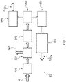
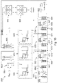
- FIG. 1 there is illustrated a block diagram of a sludge treatment plant according to a first preferred embodiment of the invention, which has been indicated as a whole with reference numeral 10.
- the plant 10 according to the invention is used for obtaining liquid methane or biomethane from sludge treatment.
- the method for treating sludge by means of the plant 10 according to the invention will also be described.
- the sludge treatment plant 10 comprises a set of stations connected to one another in series, in which sludge is subjected to various treatments for efficientlyzing the components contained in said sludge.
- the sludge treatment plant 10 comprises:
- the sludge treatment plant 10 is associated with a source of sludge 50.
- the sludge may be wastewater sludge or sludge resulting from the anaerobic digestion of agricultural by-products, livestock manure, sewage, crops or from the organic fraction of urban waste coming from the separate collection of waste.
- the source of sludge 50 comprises one or more storage tanks for storing sludge.
- the sludge coming from the source of sludge 50 have a content of moisture of about 75% of the total amount of sludge.
- the source of sludge may directly consist of the sludge outlet provided in sludge treatment plants when the plant according to the invention is arranged downstream of known sludge treatment plants.
- the first treatment station 100 comprises a HydroThermal Carbonization (HTC) reactor 101, having an inlet 101a for the sludge 50, in which the sludge coming from the source of sludge 50 is subjected to a thermochemical treatment under temperature and pressure conditions favorable for said treatment and in the presence of liquid water.
- HTC HydroThermal Carbonization
- the sludge is subjected to said hydrothermal carbonization treatment for at least 3 hours, at a temperature of 200°C and a pressure of 20 bar.
- the hydrothermal carbonization reactor 101 comprises a first, outer tube 110 for the circulation of a liquid, such as, for example, water, a second, inner tube 120 intended for the circulation of the sludge 50 and preferably arranged inside the first tube 110, and a set of rotary blades 130, preferably arranged inside the second tube 120.
- the hydrothermal carbonization reactor 101 has an outlet 101b for the sludge treated inside said reactor 101.
- the first treatment station 100 further comprises a filtration unit 102 arranged downstream of the hydrothermal carbonization reactor 101 and associated with the outlet 101b of said reactor by means of adjusting members 103 for adjusting the flow of the sludge treated by the reactor 101.
- the filtration unit 102 is a mechanical press or filter press, comprising filtration means 105 to retain the solid fraction Fs of the sludge Fi entering said filtration unit 102 and allow passage of the liquid fraction Fl that is recirculated.
- the liquid fraction Fl is sent to the hydrothermal carbonization reactor 101.
- the solid fraction Fs obtained from filtration is a carbonaceous matter
- the liquid fraction Fl is an aqueous residue rich in the substances contained in the sludge Fi, such as, for example, carbon dioxide (CO 2 ), ammonia, phosphorous, zinc and other metals.
- the filtration unit 102 At the outlet of the filtration unit 102 there are provided flow adjusting members 107, 108, such as, for example, valves, both for the exit of the solid fraction Fs and for the exit of the liquid fraction Fl that are obtained from the sludge dehydration treatment.
- the filtration unit 102 operates at a temperature of about 200°C and a pressure of about 20 bar.
- the filtration unit 102 or filter press comprising a main body 110 having an inlet 111 for the amount of sludge Fi coming from the hydrothermal carbonization reactor 101.
- the flow rate of the sludge entering the filter press 102 is adjusted by means of a valve 103.
- the filter press 102 further comprises a first, second and third outlet 112, 113, 116 for the solid fraction Fs, liquid fraction Fl and gaseous fraction Fg, respectively, obtained from the filtration of the sludge Fi entering the filter press 102.
- Filtration means 105 such as a thrust piston 114 and a plurality of stainless steel lamellas 115, are housed inside the body 110 of the filter press 102.
- the sludge Fi coming from the hydrothermal carbonization reactor enters the filter press 102 through the inlet 111.
- the valve 103 associated with the inlet 111 is open in order to allow entry of the sludge Fi
- the valves 107, 108 associated with the first and second outlets 112, 133, respectively, of the filter press 102 for exit of the solid fraction Fs and the liquid fraction Fl of the sludge are closed.
- the piston 114 is in an initial retracted position. In the illustrated embodiment, the piston 114 is slidable along a direction substantially perpendicular to the direction of entry of the sludge Fi into the filter press 102 and advances in order to perform dehydration of the amount of sludge Fi.
- the valve 103 associated with the inlet 111 for the sludge Fi is closed and the valve 108 associated with the second outlet 113 of the filter press 102, i.e. the outlet for the liquid fraction Fl contained in the sludge Fi, is opened.
- the piston 114 advances and pushes the amount of sludge Fi against the lamellas 115 carrying out the separation of the liquid fraction Fl contained in the sludge Fi.
- the liquid fraction Fl exits through the second outlet 113 of the filter press 102 and is recirculated, being sent to the hydrothermal carbonization reactor 101.
- both the valve 103 arranged at the inlet 111 for the sludge Fi and the valve 107 arranged at the first outlet 112 for the solid fraction Fs of the sludge are closed.
- valve 108 is closed and the valve 107 arranged at the first outlet 112 of the filter press 102 for the exit of the solid fraction Fs obtained from the separation of the liquid fraction Fl from the sludge is opened.
- valve 103 arranged at the inlet 111 also remains closed.
- the piston 114 continues to advance and by means of its travel it pushes the solid fraction Fs towards the first outlet 112, through which the solid fraction Fs exits the filter press 102.
- the piston 114 After having removed the solid fraction Fs from the filter press 102, the piston 114 will be in an advanced, end-of-stroke position in which the end adapted to come into contact with the sludge Fi during the pressing operation is essentially in the direction of the flow of sludge Fi entering the filter press 102.
- the valve 107 for the exit of the solid fraction Fs of the sludge is closed and the valve 103 located at the inlet 111 for the sludge Fi is opened in order to allow entry of a fresh amount of sludge to be treated.
- the sludge Upon its exit from the dehydration station 100, the sludge will have a solid fraction Fs, preferably in the form of pellets, and a gaseous fraction Fg, which fractions will be sent to the second treatment station 200 or molecular dissociation station.
- the solid fraction Fs will consist of a dry component represented by about 75% of the sludge exiting said station 100 and a moisture component represented by about the remaining part of the amount of the solid fraction Fs, i.e. about 25%.
- the gaseous fraction Fg will essentially consist of carbon dioxide CO 2 , carbon monoxide CO, methane CH 4 and hydrogen H 2 .
- the second treatment station 200 or molecular dissociation station arranged downstream of the first treatment station is adapted to receive the solid fraction Fs and the gaseous fraction Fg of the sludge coming from the first treatment station or dehydration station 100 to carry out a process of molecular dissociation of the solid fraction Fs and gaseous fraction Fg.
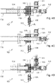
- the second treatment station 200 or molecular dissociation station comprises at least one reactor 201 provided with corresponding inlets 203, 205 for the solid fraction Fs and gaseous fraction Fg, respectively, said reactor being adapted to perform at least two treatment stages, namely a first stage S1 for the solid fraction Fs and a second stage S2 for the gaseous fraction Fg.
- the solid fraction Fs produced by the first treatment station or dehydration station 100 is turned into a gaseous phase.
- a first dissociation of complex gaseous molecules, obtained from the transformation of the solid fraction Fs into a gaseous phase, into simple molecules takes place.
- the temperature inside the reactor 201 at this first stage S1 is about 850°C.
- the reactor 201 comprises a check valve 207 for varying the thickness of the solid fraction Fs entering the reactor 201 of the molecular dissociation station 200.
- the check valve 207 is a gate valve, preferably a knife gate valve with adjustable frequency in order to vary the thickness of the solid fraction Fs.
- the reactor 201 is a vertical axis cylindrical reactor having a height of approximately 2 m and an outer diameter of approximately 1.5 m.
- the flow rate of the solid fraction Fs of the sludge at the inlet 203 of the molecular dissociation reactor 201 is about 500 kg/h.
- the path of the solid fraction Fs inside the reactor 201 of the molecular dissociation station 200 is from top to bottom, i.e. from a first, upper end 201a of the reactor 201 to a second, lower end 201b of the reactor 201 in order to define a path for the solid fraction Fs in co-current with the gaseous fraction obtained from the dissociation of the solid fraction Fs of the sludge, by exploiting the force of gravity.
- the reactor 201 of the molecular dissociation station 200 further comprises a gas feeding system 209 comprising a plurality of inlets 209a, 209b for feed gases G1, G2 for the reactor 201, such as, for example, carbon dioxide CO 2 , oxygen O 2 and water in the form of vapor, or mixtures thereof.
- a gas feeding system 209 comprising a plurality of inlets 209a, 209b for feed gases G1, G2 for the reactor 201, such as, for example, carbon dioxide CO 2 , oxygen O 2 and water in the form of vapor, or mixtures thereof.
- the reactor 201 of the molecular dissociation station 200 is fed with a mixture of gases G1, G2 comprising CO 2 , oxygen O 2 and water H 2 O in the form of vapor.
- the gas feeding system 209 comprises two inlets 209a, 209b. In other embodiments, it may comprise more than two inlets, depending on the reactions to be obtained inside the reactor 201.
- the reactor 201 of the molecular dissociation station 200 further comprises a gas distribution system 211 associated with the gas feeding system 209 at the inlet of the reactor 201 in order to distribute the feed gases G1, G2 inside the reactor 201.
- both the gas feeding system 209 and the gas distribution system 211 are arranged close to the upper end 201a of the reactor 201, in order to guarantee the path in co-current for the solid fraction Fs and the gases entering the reactor 201.
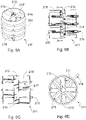
- the gas distribution system 211 comprises a housing 210 and at least one agitator 212 or mixer movable, particularly rotatable, relative to the housing 201, and driven by a corresponding electric motor 213 and provided with mixing means 215 adapted to mix gases coming from the gas feeding system 209 with the solid fraction Fs of the sludge entering the reactor 201.
- the housing 201 has a cylindrical shape.
- the mixing means 215 comprise a plurality of first arms 215' distributed in an axial direction on the body 214 of the agitator or mixer 212 and extending radially relative to the body 214 of the agitator or mixer 212.
- the first arms 215' of the agitator 212 are arranged in a sunburst pattern, offset relative to one another in order to define a plurality of reaction layers R1, R2, R3, R4, said layers being associated with the inlets 209a, 209b of the gas feeding system 209.
- the feed gases for the reactor 201 introduced through the gas feeding system 209 comprise carbon dioxide O 2 , oxygen O 2 and water H 2 O in the form of vapor, the percentages of which vary depending on the temperature and the reaction to be obtained in each reaction layer R1, R2, R3, R4.
- each first arm 215 of the agitator 212 is inclined by about 30° relative to a corresponding radial plane perpendicular to the body 214 of the agitator 21 for facilitating traveling of the solid fraction Fs downwards.
- both the body 214 and the first arms 215' of the movable agitator 212 are hollow, in order to allow the gases to flow into said body 214 and said arms 215'.
- the first arms 215' of the agitator 212 further comprise openings 217 for the exit of the gases.
- the openings 217 are oriented downwards, i.e. towards the lower end 201b of the molecular dissociation reactor 201.
- the openings 217 have a preferably circular shape and a diameter of about 3 mm.
- the openings 217 are arranged in one or more rows on respective first arms 215'.
- the gas distribution system 211 further comprises a plurality of second arms 216 stationary with respect to the housing 210 and arranged at three levels L1, L2, L3 in the illustrated embodiment.
- Each level L1, L2, L3 defined by the second stationary arms 216 is provided with a corresponding inlet nozzle 218 for the entry of the feed gases G1, G2 coming from the gas feeding system 209.
- each level L1, L2, L3 comprises two stationary arms 216 associated with a single inlet nozzle 218 by means of an annular connector 220.
- the second stationary arms 216 are arranged offset relative to the first arms 215' of the movable agitator 212.
- the stationary arms 216 in turn comprise openings 217 for the exit of gases, said openings being oriented downwards and arranged in rows on said stationary arms 216.
- the openings 217 are preferably circular and have a diameter of about 3 mm.
- the agitator 212 or mixer further comprises adjusting means for adjusting the speed of rotation to avoid areas of accumulation of the solid fraction Fs and obtain an optimal mixture as a result of the mixing of the solid fraction Fs with the gases entering the reactor 201.
- the reactor 201 of the molecular dissociation station 200 further comprises first breaking means 219 for breaking the carbonaceous particles of the solid fraction Fs that have not been gasified at the first treatment stage S1.
- first breaking means 219 are located under the gas distribution system 211.
- the first breaking means comprise first grid 219 comprising at least one mobile grid 211 moved by a corresponding motor 222 and at least one fixed grid 223.
- the fixed grid 223 has a mesh size of about 5 mm and is surmounted by first heat storage means 225 until a temperature of about 750° comprising a plurality of first iron spherical beads.
- the spherical beads 225 have a diameter between 25 mm and 35 mm, preferably of 30 mm, for allowing passage of particles smaller than 5 mm.
- the mobile grid 221 is adapted to break the carbonaceous particles of the solid fraction Fs that have not yet been gasified at the first treatment stage S1.
- the mobile grid 221 is adapted to move the first spherical beads 225 at predetermined time intervals in order to obtain breakage of carbonaceous particles having a size larger than 5 mm.
- the first spherical beads 225 are arranged in layers on the fixed grid 223.
- the overall thickness of the layers of first spherical beads 225 is sized so as to obtain, as a result of the movement of the mobile grid, optimal stirring and breakage of the carbonaceous matter. Therefore, the overall thickness of the layers of first spherical beads 225 will be between 50 mm and 70 mm, preferably 60 mm.
- the reaction temperature at this second treatment stage S2 is about 850°C.
- the reactor 201 of the molecular dissociation station 200 comprises an inlet 227 for introducing gases G3 necessary for the reaction, such as oxygen O 2 and water H 2 O in the form of vapor.
- the reactor 201 comprises a corresponding inlet 205 for the gaseous fraction Fg of the wastewater sludge obtained from the filtration carried out by the dehydration station 100.
- the gaseous fraction Fg deriving from the dehydration station 100 consists of carbon dioxide CO 2 in a proportion of 75% and the remaining 25% part consists of carbon monoxide CO, methane CH 4 and hydrogen H 2 .
- the reactor 201 of the molecular dissociation station 200 comprises second breaking means 231 arranged lower than the inlets 205, 227 provided in the reactor 201 for introducing the gases G3, Fg for the reaction of the second treatment stage S2.
- the second breaking means comprise second grids 231 comprising at least one mobile grid 223 moved by a corresponding motor 232 and at least one fixed grid 235.
- the fixed grid 235 has a mesh size of about 3 mm to allow passage of particles smaller than 3 mm.
- the fixed grid 235 is surmounted by second heat storage means 237 until a temperature of about 850°C comprising a plurality of second iron spherical beads.
- the second spherical beads 237 have a diameter between 75 mm and 85 mm, preferably of 80 mm, to allow passage of particles smaller than 3 mm.
- the second spherical beads 237 in the illustrated embodiment, are arranged in four layers on the fixed grid 233. The overall thickness of the layers of the second spherical beads 237 will be between 150 mm and 160 mm.
- the mobile grid 233 moved by the motor 232 is adapted to move the second spherical beads 237 to obtain breakage of the particles of inert gases agglomerated at the second treatment stage S2 and having a size larger than 3 mm.
- the reactor 201 of the molecular dissociation station 200 further comprises a purification system 239 for the purification of the gases exiting the second treatment stage S2 for separating gases from ashes.
- the purification system 239 comprises a plurality of cyclones 239a, 239b, located close to the lower end 201b of the reactor 201.
- the reactor 201 is further provided with an outlet 241 for the ashes coming from the purification operation performed by the cyclones 239a, 239b as well as with a collector 243 intended for collecting the ashes and located at the lower end 201b of the reactor 201.
- the reactor 201 further comprises an outlet 245 for the mixture of gases Gu obtained from the treatment performed at the second treatment stage S2.
- the mixture of gases Gu exiting the molecular dissociation station 200 consists of carbon monoxide CO, carbon dioxide CO 2 , hydrogen H 2 and water H 2 O in the form of vapor.
- the mixture of gases Gu exiting the molecular dissociation station 200 must be clean in a proportion of about 99%.
- the molecular dissociation station 200 comprises a treatment sub-station 200' or finishing station for the mixture of gases Gu exiting the molecular dissociation station 200.
- the finishing station 200' comprises a settling chamber inside which homogenization of the mixture of gases Gu coming from the molecular dissociation station 200 as well completion of the reaction times takes place. More preferably, the finishing station 200' comprises one or more dissociation reactors inside which the dissociation of complex molecules takes place by using commercially available catalysts operating at a temperature between 800°C e 900°C, more preferably at a temperature of about 850°C. In a preferred embodiment, the finishing station 200' comprises a first dissociation reactor inside which dissociation of complex gaseous molecules takes place by means of an alumina-based catalyst.
- the finishing station 200' comprises a second dissociation reactor arranged in parallel to the first reactor in order to operate in batch mode.
- the finishing station comprises a final reactor with a nickel-alumina-based catalyst.
- the sludge treatment plant 10 further comprises a third treatment station 300 or balancing station comprising at least one balancing reactor 201 which allows control of the ratio between the components hydrogen H 2 and carbon monoxide CO contained in the mixture of gases Gu subjected to the finishing treatment.
- the balancing station 300 comprises a first balancing reactor inside which the first balancing stage takes place, said first balancing reactor operating at a temperature between 330°C and 400°C, by using a ferrochromium-based catalyst, free of hexavalent chromium.
- the balancing station 300 further comprises a second balancing reactor inside which control of the ratio between hydrogen and carbon monoxide takes place by using a catalyst based on copper, zinc and alumina and the temperature is lowered by means of a heat exchanger until it reaches about 180°C and 250°C.
- the balancing station 300 further comprises detection means arranged at the entry of the first balancing reactor and at the exit of the second reactor for the treated mixture of gases.
- the detection means can detect parameters relating to the gases contained in said mixture, such as carbon monoxide, carbon dioxide, hydrogen and water.
- the detection means cooperate with an analyzing device configured to process the parameters detected by said detection means and transmit control signals for adjusting and/or varying the flow rates of the gases entering the first balancing reactor, the temperature at the exit of the first and second stage of the molecular dissociation reactor.
- the balancing station 300 When the plant according to the invention is used for obtaining liquid methane from sludge treatment, the balancing station 300 performs control of the ratio between carbon monoxide and hydrogen in order to promote the methanation reaction.
- the function of the balancing station 300 is to minimize the presence of carbon monoxide and maximize the formation of CO 2 .
- a percentage of gaseous hydrogen containing impurities lower than 10% of the obtained hydrogen is obtained.
- the sludge treatment plant further comprises a fourth treatment station or separation station 400, arranged in series downstream of the balancing station 300 and adapted to receive the mixture of gases derived from the balancing station 300, in order to separate the CO2 component to obtain a mixture of gases essentially consisting only of carbon monoxide and hydrogen.
- the separation of the carbon dioxide takes place with known means and methods.
- the sludge treatment plant 10 may further comprise a fifth treatment station 500 or liquefaction station intended for the liquefaction of the carbon dioxide component and arranged downstream of the separation station 400 for the separation of the carbon dioxide component.
- the liquefaction station receives the carbon dioxide component and comprises appropriate known systems for obtaining liquefaction of said component G CO2 and subsequently storing the same in a dedicated tank 450.
- the plant 10 according to the invention in the case in which the plant is used for obtaining liquid methane or biomethane from sludge treatment will be described below.
- the plant 10 comprises a sixth treatment station 600 or methanation station arranged downstream of the carbon dioxide component separation station 400.
- the methanation station comprises at least one methanation reactor 601, shown in Figs. 7A - 7C , having an inlet 602 adapted to receive the mixture of gases obtained from the separation of the carbon dioxide CO 2 component and subject said mixture of gases to a methanation process in order to obtain methane in the form of gas.
- the methanation reactor 601 comprises a plurality of heat exchangers 603.
- the heat exchangers 603 are arranged preferably in a circle around a longitudinal axis of said reactor 601.
- the heat exchangers 601 comprise finned tubes and extend longitudinally from a first end 601a towards a second end 601b of the methanation reactor 601.
- the heat transfer exchange medium inside the heat exchangers is water H 2 O.
- the methanation reactor 601 further comprises a feeding system 605 for feeding the heat exchange medium to the plurality of heat exchangers 603.
- the feeding system 605 comprises a first annular collector 606 provided at the lower end 601a of the methanation reactor 601 and has an inlet 604 for the heat exchange medium.
- the feeding system 605 comprises adjusting means 607, such as, for example, valves, for adjusting the flow rate of the heat exchange medium at the inlet of the heat exchangers 603.
- the pressure inside the methanation reactor 601 is about 10 bar.
- the reaction takes place from bottom to top of the methanation reactor 601 when said reactor is in its operating configuration in the plant 10.
- reaction inside the methanation reactor takes place in two steps:
- the methanation reactor 601 further comprises detection means or sensors, preferably arranged in the upper part of the reactor 601, for detecting parameters relating to the temperature of the heat exchange medium at the exit from the reactor 601 and for transmitting a control signal to the heat exchange medium flow rate adjusting means 607 provided in the lower part of the reactor 601, to adjust the flow rate of the heat exchange medium entering the reactor.
- the methanation reactor 601 further comprises two outlets 609, 611, namely a first outlet 609 for a mixture of gases Gm consisting of methane CH 4 and water H 2 O in the form of vapor, and a second outlet 611 for overheated vapor, obtained from the methanation reaction.
- the second outlet 611 is associated with a second annular collector 610 arranged at the second end 601b, i.e. at the outlet of the methanation reactor 601 arranged on top of the reactor 601 when said reactor is in its operating configuration.
- said mixture of gases Gm exiting the methanation reactor 601 will be sent to a corresponding heat exchanger 650 in order to recover the heat of the water vapor, which will subsequently be condensed in order to obtain hot water.
- the obtained hot water may be stored in an appropriate tank 660 and possibly be reused in the other stations of the plant 10.
- the methane contained in said mixture Gm will subsequently be subjected to a liquefaction process by means of known means and methods in order to obtain liquid methane G CH4 , which will be suitably stored in a dedicated tank 670.
- the overheated vapor of the second outlet 611 will be subjected to a further overheating process by means of appropriate heat exchangers.
- the reactor 601 is fed with water at a temperature of about 250°C and a pressure of about 45 bar.
- the water here used as a heat exchange medium for the heat exchangers 603, enters the reactor through the inlet 604 of the annular collector 606 arranged at the lower end 601a of the reactor 601.
- the mixture coming from the separation station 400 for the separation of the carbon dioxide component and essentially consisting of carbon monoxide and hydrogen is sent to the inlet 602 of the reactor.
- a first reaction with a first catalyst based on nickel alumina and rare metals and operating at a temperature of about 250°C takes place in the lower part of the reactor 601
- a second reaction with a second catalyst based on nickel alumina and rare metals and operating at a temperature of about 450°C takes place in the upper part of the reactor 601.
- the sludge treatment plant according to the invention may comprise a seventh treatment station or liquefaction station, arranged downstream of the methanation station 600, in order to liquefy the methane obtained in the methanation station 600.
- a seventh treatment station or liquefaction station arranged downstream of the methanation station 600, in order to liquefy the methane obtained in the methanation station 600.
- the liquefaction of methane takes place by means of methods and means known to a person skilled in the art.
- the sludge treatment plant 10 further comprises a plurality of heat exchangers and suitable compressors arranged between the various stations of the plant 10 in order to bring the treated mixture of gases to the temperature and pressure values required by each individual treatment station in order to facilitate proper operation of the plant 10.
- the first stations of the plant i.e. the stations up to and including the fifth station 400 for separating carbon dioxide CO 2
- the stations up to and including the fifth station 400 for separating carbon dioxide CO 2 are essentially the same as those previously described.
- the part of the plant 10 downstream of the separation station 400 for the separation of carbon dioxide will be described below.
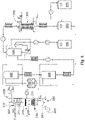
- the sixth treatment is a purification station 600' arranged downstream of the carbon dioxide component separation station 400.
- the purification station 600' is adapted to purify the component or flow of hydrogen which contains a percentage of about 10% of impurities when exiting the carbon dioxide component separation station 400.
- the impurities present in the hydrogen flow are: water H 2 O and nitrogen N 2 .
- the separation of impurities from the flow of hydrogen takes place in several stages.
- a first filtration zone for separating possible traces of solids and for separating the traces of water vapor and carbon dioxide.
- the purification station 600' comprises first filters 651 for the traces of solids, second filters 653 made as molecular sieves for separating the traces of water vapor, and third filters 655 made as molecular sieves for separating the traces of carbon dioxide.
- the first, second and third filters 651, 653, 655 are arranged in series, whereby the mixture containing hydrogen and impurities when entering the purification station 600' passes through said filters 651, 653, 655 in a cascade manner.
- the purification station 600' After separation of water and carbon dioxide, the purification station 600' has a zone for separating traces of other pollutants such as, for example, nitrogen, oxygen and methane.
- the purification station 600' comprises a demister 657 for demisting the liquid phase by cooling the mixture of gases to a temperature of about -180°C, preferably of-178°C.
- the cooling down of the mixture of gases to the temperature of -178°C takes place by means of a series of heat exchangers arranged in cascade upstream of the demister 657 in order to form a succession of cooling stages in order to reach increasingly lower temperatures from one stage to another, until a final temperature of -195°C is reached, which will then allow to liquefy by cooling the mixture of gas impurities entering the demister 657.
- the purification station 600' for the purification of the hydrogen flow comprises a refrigerating unit 662 comprising in turn a plurality of heat exchangers adapted to perform the succession of cooling stages arranged in cascade in order to provide the low temperature inside a heat exchanger 689 upstream of the demister 657.
- the refrigerating unit 662 comprises in turn:
- the final heat exchanger 689 allows to cool down the mixture of gases at the inlet of the demister 657 to a temperature of -178°C.
- the purification station 600' comprises a safety system against overpressures caused by possible stops or malfunctions of the plant.
- the safety system is made with known means and systems.
- the purification station comprises a second filtration zone for the remaining traces of impurities.
- the traces of impurities remaining in the flow of hydrogen exiting the demister 657 are separated by absorption on activated carbon filters 658 and silica gel packed beds 659.
- the pure hydrogen is stored in high pressure cylinders.
Landscapes
- Physics & Mathematics (AREA)
- Thermal Sciences (AREA)
- Life Sciences & Earth Sciences (AREA)
- Hydrology & Water Resources (AREA)
- Engineering & Computer Science (AREA)
- Environmental & Geological Engineering (AREA)
- Water Supply & Treatment (AREA)
- Chemical & Material Sciences (AREA)
- Organic Chemistry (AREA)
- Treatment Of Sludge (AREA)
Applications Claiming Priority (1)
| Application Number | Priority Date | Filing Date | Title |
|---|---|---|---|
| IT202000032966 | 2020-12-31 |
Publications (1)
| Publication Number | Publication Date |
|---|---|
| EP4023613A1 true EP4023613A1 (fr) | 2022-07-06 |
Family
ID=75111784
Family Applications (1)
| Application Number | Title | Priority Date | Filing Date |
|---|---|---|---|
| EP21218274.5A Withdrawn EP4023613A1 (fr) | 2020-12-31 | 2021-12-30 | Installation et procédé de traitement de boues |
Country Status (1)
| Country | Link |
|---|---|
| EP (1) | EP4023613A1 (fr) |
Cited By (1)
| Publication number | Priority date | Publication date | Assignee | Title |
|---|---|---|---|---|
| CN117303710A (zh) * | 2023-11-27 | 2023-12-29 | 南京昆领自控有限公司 | 一种使用液态二氧化碳进行污泥预处理的系统及处理方法 |
Citations (5)
| Publication number | Priority date | Publication date | Assignee | Title |
|---|---|---|---|---|
| US4583992A (en) * | 1984-12-04 | 1986-04-22 | Buck Rogers Mfg. Co., Inc. | Biomass gasifier and charcoal producer |
| US5264009A (en) * | 1992-09-01 | 1993-11-23 | Texaco Inc. | Processing of sewage sludge for use as a fuel |
| US6398921B1 (en) * | 1995-03-15 | 2002-06-04 | Microgas Corporation | Process and system for wastewater solids gasification and vitrification |
| US20190161374A1 (en) * | 2016-07-29 | 2019-05-30 | Tongji University | Method and system for preparing fuel gas by utilizing organic waste with high water content |
| US20190316493A1 (en) * | 2014-11-14 | 2019-10-17 | Bill & Melinda Gates Foundation | Multi-functional fecal waste and garbage processor and associated methods |
-
2021
- 2021-12-30 EP EP21218274.5A patent/EP4023613A1/fr not_active Withdrawn
Patent Citations (5)
| Publication number | Priority date | Publication date | Assignee | Title |
|---|---|---|---|---|
| US4583992A (en) * | 1984-12-04 | 1986-04-22 | Buck Rogers Mfg. Co., Inc. | Biomass gasifier and charcoal producer |
| US5264009A (en) * | 1992-09-01 | 1993-11-23 | Texaco Inc. | Processing of sewage sludge for use as a fuel |
| US6398921B1 (en) * | 1995-03-15 | 2002-06-04 | Microgas Corporation | Process and system for wastewater solids gasification and vitrification |
| US20190316493A1 (en) * | 2014-11-14 | 2019-10-17 | Bill & Melinda Gates Foundation | Multi-functional fecal waste and garbage processor and associated methods |
| US20190161374A1 (en) * | 2016-07-29 | 2019-05-30 | Tongji University | Method and system for preparing fuel gas by utilizing organic waste with high water content |
Cited By (2)
| Publication number | Priority date | Publication date | Assignee | Title |
|---|---|---|---|---|
| CN117303710A (zh) * | 2023-11-27 | 2023-12-29 | 南京昆领自控有限公司 | 一种使用液态二氧化碳进行污泥预处理的系统及处理方法 |
| CN117303710B (zh) * | 2023-11-27 | 2024-04-05 | 南京昆领自控有限公司 | 一种使用液态二氧化碳进行污泥预处理的系统及处理方法 |
Similar Documents
| Publication | Publication Date | Title |
|---|---|---|
| JP2021100911A (ja) | 生物起源の活性炭ならびにそれを作製および使用する方法 | |
| US4252901A (en) | System and process for anaerobic digestion | |
| JP2000290659A (ja) | 燃料ガスの製造方法 | |
| KR101885932B1 (ko) | 플래시 용기의 탈기 시스템 | |
| JP2000290670A (ja) | 燃料ガスの製造方法 | |
| KR102430685B1 (ko) | 용액 배쓰 형태의 고농도 황화수소 제거 장치 | |
| EP4023613A1 (fr) | Installation et procédé de traitement de boues | |
| FI92600C (fi) | Menetelmä ja laite palavien saaste- tai jäteaineiden muuntamiseksi puhtaaksi energiaksi ja käyttökelpoisiksi tuotteiksi | |
| JP2026009353A (ja) | 有機物質の製造方法、及び有機物質製造装置 | |
| JP2026015334A (ja) | 熱分解ガス精製冷却装置及び熱分解ガス精製冷却方法、並びに、有機物質製造装置及び有機物質の製造方法 | |
| JP3165884B2 (ja) | 有機固形廃棄物と液状廃棄物との同時処理方法 | |
| RU2536510C2 (ru) | Каталитический реактор для переработки осадков сточных вод и способ их переработки (варианты) | |
| AU2014227165B2 (en) | Gas purification device and gas purification method | |
| JP2000117272A (ja) | 廃水の処理方法 | |
| JP4703227B2 (ja) | 廃水の処理方法 | |
| JP3528023B2 (ja) | 含水廃棄物の処理方法 | |
| CN104194837A (zh) | 一种有机物废水的无害化处理工艺及其装置 | |
| RU2414282C1 (ru) | Способ утилизации биогаза метантенков | |
| CN106853317A (zh) | 酸性水汽提氨气的脱硫净化工艺 | |
| EP3175909B1 (fr) | Procédé et appareil de nettoyage de gaz contaminé dans un réacteur avec du matériel élastique | |
| AU2005205757B2 (en) | Process for the treatment of water and thermal treatment system | |
| JP4651014B2 (ja) | 被処理物ガス化システムと被処理物ガス化方法 | |
| JPS6054119B2 (ja) | 固体廃棄物及び下水汚泥の処理物から資源を回収する方法 | |
| JP7708674B2 (ja) | 有機物質の製造方法及び有機物質製造装置 | |
| JP4154553B2 (ja) | 燃料ガスの製造方法 |
Legal Events
| Date | Code | Title | Description |
|---|---|---|---|
| PUAI | Public reference made under article 153(3) epc to a published international application that has entered the european phase |
Free format text: ORIGINAL CODE: 0009012 |
|
| STAA | Information on the status of an ep patent application or granted ep patent |
Free format text: STATUS: THE APPLICATION HAS BEEN PUBLISHED |
|
| AK | Designated contracting states |
Kind code of ref document: A1 Designated state(s): AL AT BE BG CH CY CZ DE DK EE ES FI FR GB GR HR HU IE IS IT LI LT LU LV MC MK MT NL NO PL PT RO RS SE SI SK SM TR |
|
| STAA | Information on the status of an ep patent application or granted ep patent |
Free format text: STATUS: THE APPLICATION IS DEEMED TO BE WITHDRAWN |
|
| 18D | Application deemed to be withdrawn |
Effective date: 20230110 |