EP4023822A1 - Behältermesssystem - Google Patents
Behältermesssystem Download PDFInfo
- Publication number
- EP4023822A1 EP4023822A1 EP20868142.9A EP20868142A EP4023822A1 EP 4023822 A1 EP4023822 A1 EP 4023822A1 EP 20868142 A EP20868142 A EP 20868142A EP 4023822 A1 EP4023822 A1 EP 4023822A1
- Authority
- EP
- European Patent Office
- Prior art keywords
- container
- information
- dimensional
- dimensional information
- distance image
- Prior art date
- Legal status (The legal status is an assumption and is not a legal conclusion. Google has not performed a legal analysis and makes no representation as to the accuracy of the status listed.)
- Pending
Links
Images


Classifications
-
- G—PHYSICS
- G06—COMPUTING OR CALCULATING; COUNTING
- G06T—IMAGE DATA PROCESSING OR GENERATION, IN GENERAL
- G06T7/00—Image analysis
- G06T7/50—Depth or shape recovery
- G06T7/55—Depth or shape recovery from multiple images
-
- E—FIXED CONSTRUCTIONS
- E02—HYDRAULIC ENGINEERING; FOUNDATIONS; SOIL SHIFTING
- E02F—DREDGING; SOIL-SHIFTING
- E02F9/00—Component parts of dredgers or soil-shifting machines, not restricted to one of the kinds covered by groups E02F3/00 - E02F7/00
- E02F9/26—Indicating devices
- E02F9/261—Surveying the work-site to be treated
- E02F9/262—Surveying the work-site to be treated with follow-up actions to control the work tool, e.g. controller
-
- B—PERFORMING OPERATIONS; TRANSPORTING
- B65—CONVEYING; PACKING; STORING; HANDLING THIN OR FILAMENTARY MATERIAL
- B65G—TRANSPORT OR STORAGE DEVICES, e.g. CONVEYORS FOR LOADING OR TIPPING, SHOP CONVEYOR SYSTEMS OR PNEUMATIC TUBE CONVEYORS
- B65G67/00—Loading or unloading vehicles
- B65G67/02—Loading or unloading land vehicles
- B65G67/04—Loading land vehicles
-
- E—FIXED CONSTRUCTIONS
- E02—HYDRAULIC ENGINEERING; FOUNDATIONS; SOIL SHIFTING
- E02F—DREDGING; SOIL-SHIFTING
- E02F3/00—Dredgers; Soil-shifting machines
- E02F3/04—Dredgers; Soil-shifting machines mechanically-driven
- E02F3/28—Dredgers; Soil-shifting machines mechanically-driven with digging tools mounted on a dipper- or bucket-arm, i.e. there is either one arm or a pair of arms, e.g. dippers, buckets
-
- E—FIXED CONSTRUCTIONS
- E02—HYDRAULIC ENGINEERING; FOUNDATIONS; SOIL SHIFTING
- E02F—DREDGING; SOIL-SHIFTING
- E02F3/00—Dredgers; Soil-shifting machines
- E02F3/04—Dredgers; Soil-shifting machines mechanically-driven
- E02F3/28—Dredgers; Soil-shifting machines mechanically-driven with digging tools mounted on a dipper- or bucket-arm, i.e. there is either one arm or a pair of arms, e.g. dippers, buckets
- E02F3/36—Component parts
- E02F3/42—Drives for dippers, buckets, dipper-arms or bucket-arms
- E02F3/43—Control of dipper or bucket position; Control of sequence of drive operations
- E02F3/435—Control of dipper or bucket position; Control of sequence of drive operations for dipper-arms, backhoes or the like
- E02F3/439—Automatic repositioning of the implement, e.g. automatic dumping, auto-return
-
- E—FIXED CONSTRUCTIONS
- E02—HYDRAULIC ENGINEERING; FOUNDATIONS; SOIL SHIFTING
- E02F—DREDGING; SOIL-SHIFTING
- E02F9/00—Component parts of dredgers or soil-shifting machines, not restricted to one of the kinds covered by groups E02F3/00 - E02F7/00
- E02F9/20—Drives; Control devices
- E02F9/2025—Particular purposes of control systems not otherwise provided for
-
- E—FIXED CONSTRUCTIONS
- E02—HYDRAULIC ENGINEERING; FOUNDATIONS; SOIL SHIFTING
- E02F—DREDGING; SOIL-SHIFTING
- E02F9/00—Component parts of dredgers or soil-shifting machines, not restricted to one of the kinds covered by groups E02F3/00 - E02F7/00
- E02F9/26—Indicating devices
-
- G—PHYSICS
- G01—MEASURING; TESTING
- G01B—MEASURING LENGTH, THICKNESS OR SIMILAR LINEAR DIMENSIONS; MEASURING ANGLES; MEASURING AREAS; MEASURING IRREGULARITIES OF SURFACES OR CONTOURS
- G01B11/00—Measuring arrangements characterised by the use of optical techniques
- G01B11/002—Measuring arrangements characterised by the use of optical techniques for measuring two or more coordinates
-
- G—PHYSICS
- G01—MEASURING; TESTING
- G01B—MEASURING LENGTH, THICKNESS OR SIMILAR LINEAR DIMENSIONS; MEASURING ANGLES; MEASURING AREAS; MEASURING IRREGULARITIES OF SURFACES OR CONTOURS
- G01B11/00—Measuring arrangements characterised by the use of optical techniques
- G01B11/02—Measuring arrangements characterised by the use of optical techniques for measuring length, width or thickness
- G01B11/026—Measuring arrangements characterised by the use of optical techniques for measuring length, width or thickness by measuring distance between sensor and object
-
- G—PHYSICS
- G01—MEASURING; TESTING
- G01B—MEASURING LENGTH, THICKNESS OR SIMILAR LINEAR DIMENSIONS; MEASURING ANGLES; MEASURING AREAS; MEASURING IRREGULARITIES OF SURFACES OR CONTOURS
- G01B11/00—Measuring arrangements characterised by the use of optical techniques
- G01B11/24—Measuring arrangements characterised by the use of optical techniques for measuring contours or curvatures
-
- G—PHYSICS
- G01—MEASURING; TESTING
- G01S—RADIO DIRECTION-FINDING; RADIO NAVIGATION; DETERMINING DISTANCE OR VELOCITY BY USE OF RADIO WAVES; LOCATING OR PRESENCE-DETECTING BY USE OF THE REFLECTION OR RERADIATION OF RADIO WAVES; ANALOGOUS ARRANGEMENTS USING OTHER WAVES
- G01S17/00—Systems using the reflection or reradiation of electromagnetic waves other than radio waves, e.g. lidar systems
- G01S17/88—Lidar systems specially adapted for specific applications
- G01S17/89—Lidar systems specially adapted for specific applications for mapping or imaging
- G01S17/894—Three-dimensional [3D] imaging with simultaneous measurement of time-of-flight at a two-dimensional [2D] array of receiver pixels, e.g. time-of-flight cameras or flash lidar
-
- G—PHYSICS
- G06—COMPUTING OR CALCULATING; COUNTING
- G06T—IMAGE DATA PROCESSING OR GENERATION, IN GENERAL
- G06T7/00—Image analysis
- G06T7/50—Depth or shape recovery
- G06T7/521—Depth or shape recovery from laser ranging, e.g. using interferometry; from the projection of structured light
-
- G—PHYSICS
- G06—COMPUTING OR CALCULATING; COUNTING
- G06T—IMAGE DATA PROCESSING OR GENERATION, IN GENERAL
- G06T7/00—Image analysis
- G06T7/60—Analysis of geometric attributes
-
- G—PHYSICS
- G06—COMPUTING OR CALCULATING; COUNTING
- G06T—IMAGE DATA PROCESSING OR GENERATION, IN GENERAL
- G06T7/00—Image analysis
- G06T7/60—Analysis of geometric attributes
- G06T7/62—Analysis of geometric attributes of area, perimeter, diameter or volume
-
- G—PHYSICS
- G06—COMPUTING OR CALCULATING; COUNTING
- G06T—IMAGE DATA PROCESSING OR GENERATION, IN GENERAL
- G06T7/00—Image analysis
- G06T7/70—Determining position or orientation of objects or cameras
- G06T7/73—Determining position or orientation of objects or cameras using feature-based methods
-
- G—PHYSICS
- G06—COMPUTING OR CALCULATING; COUNTING
- G06T—IMAGE DATA PROCESSING OR GENERATION, IN GENERAL
- G06T2200/00—Indexing scheme for image data processing or generation, in general
- G06T2200/04—Indexing scheme for image data processing or generation, in general involving 3D image data
-
- G—PHYSICS
- G06—COMPUTING OR CALCULATING; COUNTING
- G06T—IMAGE DATA PROCESSING OR GENERATION, IN GENERAL
- G06T2207/00—Indexing scheme for image analysis or image enhancement
- G06T2207/10—Image acquisition modality
- G06T2207/10004—Still image; Photographic image
- G06T2207/10012—Stereo images
-
- G—PHYSICS
- G06—COMPUTING OR CALCULATING; COUNTING
- G06T—IMAGE DATA PROCESSING OR GENERATION, IN GENERAL
- G06T2207/00—Indexing scheme for image analysis or image enhancement
- G06T2207/10—Image acquisition modality
- G06T2207/10028—Range image; Depth image; 3D point clouds
-
- G—PHYSICS
- G06—COMPUTING OR CALCULATING; COUNTING
- G06T—IMAGE DATA PROCESSING OR GENERATION, IN GENERAL
- G06T2207/00—Indexing scheme for image analysis or image enhancement
- G06T2207/30—Subject of image; Context of image processing
- G06T2207/30248—Vehicle exterior or interior
- G06T2207/30252—Vehicle exterior; Vicinity of vehicle
-
- G—PHYSICS
- G06—COMPUTING OR CALCULATING; COUNTING
- G06T—IMAGE DATA PROCESSING OR GENERATION, IN GENERAL
- G06T2207/00—Indexing scheme for image analysis or image enhancement
- G06T2207/30—Subject of image; Context of image processing
- G06T2207/30248—Vehicle exterior or interior
- G06T2207/30252—Vehicle exterior; Vicinity of vehicle
- G06T2207/30261—Obstacle
Definitions
- the present invention relates to a container measuring system for calculating three-dimensional information on a container.
- Patent Literature 1 discloses a technology calculating three-dimensional information on a container. According to the technology disclosed in this Literature, an image of four characteristic points of a container is taken by a camera, and a three-dimensional position of each characteristic point is calculated.
- Patent Literature 1 Japanese Unexamined Patent Publication No. 2000-064359
- an object of the present invention is to provide a container measuring system which enables a stable calculation of three-dimensional information on a container.
- a container measuring system includes a distance image acquiring part and a calculation part.
- the distance image acquiring part is provided on a working machine for performing a work of loading into a container including a flat face part, and is capable of acquiring a distance image of the container.
- the calculation part processes the distance image of the container acquired by the distance image acquiring part.
- the calculation part calculates a three-dimensional position of the flat face part on the basis of the distance image of the container.
- the calculation part calculates three-dimensional information including a three-dimensional position and a three-dimensional shape of the container on the basis of the three-dimensional position of the flat face part.
- the container 12 contains the transport matter.
- the transport matter placed in the container 12 is, for example, earth and sand, or wastes (such as industrial waste).
- the container 12 serves as a box bed provided on the transport vehicle 10.
- the container 12 is provided behind the operating room 11a or on a rear portion of the transport vehicle 10.
- directions of the transport vehicle 10 are referred to as "rearward in view of the transport vehicle” for a direction from the operating room 11a to the container 12, and to as “forward in view of the transport vehicle” for a direction from the container 12 to the operating room 11a.
- the container 12 is movable against the main body part 11, or may be fixedly provided on the main body part 11.
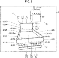
- the container 12 has, for example, a box shape having no lid (see FIG. 2 ).
- the container 12 defines a flat face part 13.
- the container 12 may not be provided on the transport vehicle 10 as the box bed, but may be, for example, placed directly on the ground. The following description will be made about the case where the container 12 is the
- the flat face part 13 is a section of the container 12 that is flat or substantially flat as shown in FIG. 2 .
- the flat face part 13 appears to be largely flat or substantially flat over a whole extent.
- the flat face part 13 has a recess and projection, or a generally curved surface to some extent.
- the flat face part 13 includes a floor surface 13a, a rear surface 13b, side surfaces 13c, and a front surface 13d.
- the floor surface 13a is a bottom surface (a lower surface) of the container 12.
- the rear surface 13b is a surface of the container 12 that is rearward in view of the transport vehicle, and protrudes upwardly from a section of the floor surface 13a that is rearward in view of the transport vehicle.
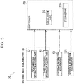
- the container measuring system 30 (see FIG. 3 ) is a system for obtaining information of three dimensions (three-dimensional information) of the container 12.
- the container measuring system 30 measures a position, a direction, and a shape of the container 12 with respect to the working machine 20.
- the container measuring system 30 includes a distance image acquiring part 40, a coordinate information acquiring part 51, and a controller 50 as shown in FIG. 3 .
- An operation information acquiring part 155 shown in FIG. 3 will be described later.
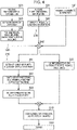
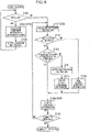
- the calculation part 53 shown in FIG. 3 executes the two-dimensional information processing S20 (see FIG. 4 ).
- the reason therefor will be described hereinafter.
- a distance image D acquired by the three-dimensional information acquiring part 43 could be hardly processed in the raw by the calculation part 53. It is inferred, for example, a case where the processing speed becomes low.
- the calculation part 53 extracts a position of the container 12 (see FIG. 2 ) in two-dimensional information (hereinafter, referred to as "image") acquired by the two-dimensional information acquiring part 42.
- image two-dimensional information
- the calculation part 53 extracts a section (a part of points data) in an image that corresponds to the position of the container 12 (see FIG.
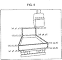
- the characteristic points F are points corresponding to corners of the flat face part 13.
- the links L are lines connecting characteristic points F to one another, and corresponding to, for example, sides of the flat face part 13.
- the positions of the characteristic points F respectively correspond to positions of two points (F1, F2) in an upper end of the front surface 13d, positions of two points (F3, F4) in upper ends of two side surfaces 13c which are forward in view of the transport vehicle, and positions of four points (F5 to F8) at corners of the rear surface 13b.
- a position in the lower end of the front surface 13d may be extracted as a characteristic point F (see FIG. 1 ).
- FIG. 1 a position in the lower end of the front surface 13d may be extracted as a characteristic point F (see FIG. 1 ).
- the positions of the links L respectively correspond to positions of four sides (L1 to L4) of a quadrilateral portion of the front surface 13d that is above the side surfaces 13c.
- the positions of the links L respectively correspond to positions of upper sides (L5, L6) of the side surfaces 13c and four sides (L7 to L10) of the rear surface 13b (more specifically, four sides of a quadrilateral substantially overlapping the rear surface 13b).
- the three-dimensional information acquiring part 43 acquires the distance images D including the container 12 (Step S31 shown in FIG. 4 ). Information on the distance images D is input to the calculation part 53. Specifically, the calculation part 53 acquires data concerning a group of points (hereinafter, simply referred to as "group of points") for dimensional information (Step S32 shown in FIG. 4 ).
- the calculation part 53 calculates the three-dimensional position of the flat face part 13 constituting the container 12 on the basis of the distance image D of the container 12. Specifically, the calculation part 53 executes the following processing.
- the calculation part 53 determines (selects) a group of points to be extracted from the distance image D on the basis of positions of the links L in the image. More specifically, the calculation part 53 extracts a group of points of a section (within a scope) which is surrounded by the links L and corresponds to the flat face part 13 from the distance image D. Specifically, the calculation part 53 extracts a group of points of a section surrounded by the links L1, L2, L3, and L4 in the case of extracting a group of points of the front surface 13d from the distance image D. The calculation part 53 extracts a group of points of a section surrounded by the links L7, L8, L9, and L10 in a case of extracting a group of points of the rear surface 13b from the distance image D.
- the processing for "the three-dimensional information on characteristic points F and links L (Processing S50)" three-dimensional positions of the links L are calculated, and thus, information on a shape (external shape) of the flat face part 13 is calculated.
- the processing (S60) for the three-dimensional information of the flat face part 13 the three-dimensional information on the flat face part 13 to be calculated by the calculation part 53 may include or may not include information on the shape (external shape) of the flat face part 13.
- the three-dimensional information on the container 12 may be used for various controls.
- the three-dimensional information on the container 12 may be used for an automatic operation of the working machine 20 shown in FIG. 1 , or may be used for assisting an operation of the working machine 20.
- the three-dimensional information on the container 12 may be used for a control (such as a control to automatically regulate a motion or send a notification) to avoid collision between the working machine 20 and the container 12.
- the three-dimensional information on the container 12 may be used for a control for a relative position between the working machine 20 and the container 12.
- the calculation part 53 calculates (estimates) three-dimensional information on the container 12 (see FIG. 7 ) after the execution of the operation ⁇ on the basis of the three-dimensional information on the container 12 before the execution of the operation ⁇ and the information on the operation ⁇ .
- the following description will be made mainly about a specific example of processings of the calculation part 53 (see FIG. 3 , below-described calculation parts 53 are the same) mainly with reference to FIG. 6 .
- the calculation part 53 updates the stored three-dimensional information to the current three-dimensional information (Step S115 shown in FIG. 6 ).
- the calculation part 53 may output a signal to an internal portion or an outside of the calculation part 53 (Step S114 shown in FIG. 6 ).
- the calculation part 53 may output information showing the update of the three-dimensional information to another processing (e.g., a control) executed by the calculation part 53.
- the calculation part 53 may output, for example, a notification (such as an alarm) to an operator of the working machine 20 and the like. This notification may be a sound or a display.
- three-dimensional information on the container is calculated on the basis of a three-dimensional position of the flat face part. Therefore, the three-dimensional information on the container can be calculated at a stably higher accuracy compared with a case where the three-dimensional information on the container is calculated on the basis of the three-dimensional positions of only points such as characteristic points, for example. Consequently, the three-dimensional information on the container can be suitably applied to a control and the like.
- the calculation part can calculate three-dimensional information on the container at a high accuracy on the basis of the stored three-dimensional information and the information on the operation even when at least a section of the container is beyond the distance image.
Landscapes
- Engineering & Computer Science (AREA)
- Physics & Mathematics (AREA)
- General Physics & Mathematics (AREA)
- Computer Vision & Pattern Recognition (AREA)
- Theoretical Computer Science (AREA)
- Mining & Mineral Resources (AREA)
- Civil Engineering (AREA)
- General Engineering & Computer Science (AREA)
- Structural Engineering (AREA)
- Mechanical Engineering (AREA)
- Geometry (AREA)
- Optics & Photonics (AREA)
- Aviation & Aerospace Engineering (AREA)
- Computer Networks & Wireless Communication (AREA)
- Electromagnetism (AREA)
- Radar, Positioning & Navigation (AREA)
- Remote Sensing (AREA)
- Length Measuring Devices By Optical Means (AREA)
- Component Parts Of Construction Machinery (AREA)
- Image Analysis (AREA)
Applications Claiming Priority (2)
| Application Number | Priority Date | Filing Date | Title |
|---|---|---|---|
| JP2019176035A JP7283332B2 (ja) | 2019-09-26 | 2019-09-26 | 容器計測システム |
| PCT/JP2020/031818 WO2021059823A1 (ja) | 2019-09-26 | 2020-08-24 | 容器計測システム |
Publications (2)
| Publication Number | Publication Date |
|---|---|
| EP4023822A1 true EP4023822A1 (de) | 2022-07-06 |
| EP4023822A4 EP4023822A4 (de) | 2022-11-23 |
Family
ID=75166068
Family Applications (1)
| Application Number | Title | Priority Date | Filing Date |
|---|---|---|---|
| EP20868142.9A Pending EP4023822A4 (de) | 2019-09-26 | 2020-08-24 | Behältermesssystem |
Country Status (5)
| Country | Link |
|---|---|
| US (1) | US12307697B2 (de) |
| EP (1) | EP4023822A4 (de) |
| JP (1) | JP7283332B2 (de) |
| CN (1) | CN114521228A (de) |
| WO (1) | WO2021059823A1 (de) |
Families Citing this family (8)
| Publication number | Priority date | Publication date | Assignee | Title |
|---|---|---|---|---|
| CN111919003A (zh) * | 2018-03-26 | 2020-11-10 | 住友建机株式会社 | 挖土机 |
| JP7602741B2 (ja) * | 2020-05-25 | 2024-12-19 | 住友建機株式会社 | ショベル用のシステム |
| US12123162B2 (en) * | 2021-09-29 | 2024-10-22 | Caterpillar Sarl | System, method, and apparatus for accurately determining payload transfer |
| JP7843579B2 (ja) * | 2022-04-04 | 2026-04-10 | 日立建機株式会社 | 作業機械 |
| CN119404225A (zh) * | 2022-07-05 | 2025-02-07 | 索尼半导体解决方案公司 | 系统和程序 |
| US12545515B1 (en) * | 2023-06-12 | 2026-02-10 | Amazon Technologies, Inc. | Stereo structured light machine vision system for guidance of automated tote exchange equipment |
| US12552039B1 (en) | 2023-09-29 | 2026-02-17 | Amazon Technologies, Inc. | Automated calibration of a machine vision system |
| JP2025160569A (ja) * | 2024-04-10 | 2025-10-23 | 日立建機株式会社 | 運搬車両認識システム及び作業機械 |
Family Cites Families (20)
| Publication number | Priority date | Publication date | Assignee | Title |
|---|---|---|---|---|
| JPH11211438A (ja) * | 1998-01-22 | 1999-08-06 | Komatsu Ltd | 荷台積載体積計測装置 |
| JP2000064359A (ja) | 1998-08-24 | 2000-02-29 | Hitachi Constr Mach Co Ltd | 自動運転建設機械 |
| JP2000192514A (ja) * | 1998-12-28 | 2000-07-11 | Hitachi Constr Mach Co Ltd | 自動運転建設機械およびその運転方法 |
| JP5135380B2 (ja) * | 2010-04-12 | 2013-02-06 | 住友重機械工業株式会社 | 処理対象画像生成装置、処理対象画像生成方法、及び操作支援システム |
| JP6004809B2 (ja) | 2012-03-13 | 2016-10-12 | キヤノン株式会社 | 位置姿勢推定装置、情報処理装置、情報処理方法 |
| JP6193075B2 (ja) * | 2013-09-30 | 2017-09-06 | 株式会社小松製作所 | 運搬機械 |
| CN104476552B (zh) * | 2014-10-30 | 2016-08-24 | 佛山金皇宇机械实业有限公司 | 一种基于机器视觉的机器人型材搬运装置的搬运方法 |
| JP6407663B2 (ja) * | 2014-10-30 | 2018-10-17 | 日立建機株式会社 | 作業支援画像生成装置、及びそれを備えた作業機械の操縦システム |
| US10208459B2 (en) * | 2014-12-12 | 2019-02-19 | Hitachi, Ltd. | Volume estimation device and work machine using same |
| US20180120098A1 (en) | 2015-04-24 | 2018-05-03 | Hitachi, Ltd. | Volume Estimation Apparatus, Working Machine Including the Same, and Volume Estimation System |
| CN106839975B (zh) | 2015-12-03 | 2019-08-30 | 杭州海康威视数字技术股份有限公司 | 基于深度相机的体积测量方法及其系统 |
| WO2017184037A1 (en) * | 2016-04-19 | 2017-10-26 | Volvo Construction Equipment Ab | Control unit for dumping of material |
| US10815640B2 (en) | 2016-08-31 | 2020-10-27 | Komatsu Ltd. | Wheel loader and method for controlling wheel loader |
| US10570582B2 (en) | 2016-11-23 | 2020-02-25 | Caterpillar Inc. | System and method for operating a material-handling machine |
| US10801177B2 (en) * | 2017-01-23 | 2020-10-13 | Built Robotics Inc. | Excavating earth from a dig site using an excavation vehicle |
| US10984524B2 (en) | 2017-12-21 | 2021-04-20 | Advanced Ion Beam Technology, Inc. | Calibration system with at least one camera and method thereof |
| EP3673233B1 (de) * | 2018-04-18 | 2025-09-10 | Mobileye Vision Technologies Ltd. | Fahrzeugumgebungsmodellierung mit einer kamera |
| JP7166108B2 (ja) * | 2018-08-31 | 2022-11-07 | 株式会社小松製作所 | 画像処理システム、表示装置、画像処理方法、学習済みモデルの生成方法、および学習用データセット |
| JP7365122B2 (ja) * | 2019-02-01 | 2023-10-19 | 株式会社小松製作所 | 画像処理システムおよび画像処理方法 |
| CN109903337B (zh) | 2019-02-28 | 2022-06-14 | 北京百度网讯科技有限公司 | 用于确定挖掘机的铲斗的位姿的方法和装置 |
-
2019
- 2019-09-26 JP JP2019176035A patent/JP7283332B2/ja active Active
-
2020
- 2020-08-24 US US17/762,885 patent/US12307697B2/en active Active
- 2020-08-24 EP EP20868142.9A patent/EP4023822A4/de active Pending
- 2020-08-24 CN CN202080066936.8A patent/CN114521228A/zh active Pending
- 2020-08-24 WO PCT/JP2020/031818 patent/WO2021059823A1/ja not_active Ceased
Also Published As
| Publication number | Publication date |
|---|---|
| JP7283332B2 (ja) | 2023-05-30 |
| EP4023822A4 (de) | 2022-11-23 |
| WO2021059823A1 (ja) | 2021-04-01 |
| JP2021056543A (ja) | 2021-04-08 |
| CN114521228A (zh) | 2022-05-20 |
| US20220343524A1 (en) | 2022-10-27 |
| US12307697B2 (en) | 2025-05-20 |
Similar Documents
| Publication | Publication Date | Title |
|---|---|---|
| EP4023822A1 (de) | Behältermesssystem | |
| AU2022209235B2 (en) | Display control device and display control method | |
| US12094151B2 (en) | Image processing system, image processing method, learned model generation method, and data set for learning | |
| US11414837B2 (en) | Image processing system, display device, image processing method, method for generating trained model, and dataset for learning | |
| US12088968B2 (en) | Display control device, display control system, and display control method | |
| US9251587B2 (en) | Motion estimation utilizing range detection-enhanced visual odometry | |
| US11100663B2 (en) | Construction management device and construction management method | |
| US11459735B2 (en) | Display control system, display control device, and display control method | |
| KR20210151964A (ko) | 건설 기계 | |
| US20210272315A1 (en) | Transport object specifying device of work machine, work machine, transport object specifying method of work machine, method for producing complementary model, and dataset for learning | |
| EP4269710A1 (de) | Behältermesssystem | |
| JP7421788B2 (ja) | 衛星測位方法、衛星測位装置、衛星測位システム及び建設機械 | |
| US12348851B2 (en) | Display control device and display method | |
| EP3757299B1 (de) | Vorrichtung zur erzeugung von umgebungsdaten um bauausrüstung herum und bauausrüstung damit | |
| US20260087752A1 (en) | Image generation device and operation assistance system | |
| AU2021352215B2 (en) | Display control device and display control method | |
| US12518405B2 (en) | Visual localization and feature detection for an implement tracking system |
Legal Events
| Date | Code | Title | Description |
|---|---|---|---|
| STAA | Information on the status of an ep patent application or granted ep patent |
Free format text: STATUS: THE INTERNATIONAL PUBLICATION HAS BEEN MADE |
|
| PUAI | Public reference made under article 153(3) epc to a published international application that has entered the european phase |
Free format text: ORIGINAL CODE: 0009012 |
|
| STAA | Information on the status of an ep patent application or granted ep patent |
Free format text: STATUS: REQUEST FOR EXAMINATION WAS MADE |
|
| 17P | Request for examination filed |
Effective date: 20220328 |
|
| AK | Designated contracting states |
Kind code of ref document: A1 Designated state(s): AL AT BE BG CH CY CZ DE DK EE ES FI FR GB GR HR HU IE IS IT LI LT LU LV MC MK MT NL NO PL PT RO RS SE SI SK SM TR |
|
| A4 | Supplementary search report drawn up and despatched |
Effective date: 20221021 |
|
| RIC1 | Information provided on ipc code assigned before grant |
Ipc: G06T 7/62 20170101ALI20221017BHEP Ipc: G01B 11/24 20060101ALI20221017BHEP Ipc: G01B 11/00 20060101ALI20221017BHEP Ipc: E02F 3/43 20060101ALI20221017BHEP Ipc: B60P 1/04 20060101ALI20221017BHEP Ipc: E02F 9/26 20060101AFI20221017BHEP |
|
| DAV | Request for validation of the european patent (deleted) | ||
| DAX | Request for extension of the european patent (deleted) | ||
| STAA | Information on the status of an ep patent application or granted ep patent |
Free format text: STATUS: EXAMINATION IS IN PROGRESS |
|
| 17Q | First examination report despatched |
Effective date: 20230419 |