EP4023823B1 - Dispositif pour évaluer la position d'un véhicule de transport - Google Patents
Dispositif pour évaluer la position d'un véhicule de transport Download PDFInfo
- Publication number
- EP4023823B1 EP4023823B1 EP20869069.3A EP20869069A EP4023823B1 EP 4023823 B1 EP4023823 B1 EP 4023823B1 EP 20869069 A EP20869069 A EP 20869069A EP 4023823 B1 EP4023823 B1 EP 4023823B1
- Authority
- EP
- European Patent Office
- Prior art keywords
- box bed
- transport vehicle
- dischargeable
- scope
- dischargeable region
- Prior art date
- Legal status (The legal status is an assumption and is not a legal conclusion. Google has not performed a legal analysis and makes no representation as to the accuracy of the status listed.)
- Active
Links
Images


Classifications
-
- B—PERFORMING OPERATIONS; TRANSPORTING
- B65—CONVEYING; PACKING; STORING; HANDLING THIN OR FILAMENTARY MATERIAL
- B65G—TRANSPORT OR STORAGE DEVICES, e.g. CONVEYORS FOR LOADING OR TIPPING, SHOP CONVEYOR SYSTEMS OR PNEUMATIC TUBE CONVEYORS
- B65G67/00—Loading or unloading vehicles
- B65G67/02—Loading or unloading land vehicles
- B65G67/04—Loading land vehicles
-
- E—FIXED CONSTRUCTIONS
- E02—HYDRAULIC ENGINEERING; FOUNDATIONS; SOIL SHIFTING
- E02F—DREDGING; SOIL-SHIFTING
- E02F9/00—Component parts of dredgers or soil-shifting machines, not restricted to one of the kinds covered by groups E02F3/00 - E02F7/00
- E02F9/20—Drives; Control devices
- E02F9/2025—Particular purposes of control systems not otherwise provided for
- E02F9/205—Remotely operated machines, e.g. unmanned vehicles
-
- E—FIXED CONSTRUCTIONS
- E02—HYDRAULIC ENGINEERING; FOUNDATIONS; SOIL SHIFTING
- E02F—DREDGING; SOIL-SHIFTING
- E02F3/00—Dredgers; Soil-shifting machines
- E02F3/04—Dredgers; Soil-shifting machines mechanically-driven
- E02F3/28—Dredgers; Soil-shifting machines mechanically-driven with digging tools mounted on a dipper- or bucket-arm, i.e. there is either one arm or a pair of arms, e.g. dippers, buckets
- E02F3/36—Component parts
-
- E—FIXED CONSTRUCTIONS
- E02—HYDRAULIC ENGINEERING; FOUNDATIONS; SOIL SHIFTING
- E02F—DREDGING; SOIL-SHIFTING
- E02F9/00—Component parts of dredgers or soil-shifting machines, not restricted to one of the kinds covered by groups E02F3/00 - E02F7/00
-
- E—FIXED CONSTRUCTIONS
- E02—HYDRAULIC ENGINEERING; FOUNDATIONS; SOIL SHIFTING
- E02F—DREDGING; SOIL-SHIFTING
- E02F9/00—Component parts of dredgers or soil-shifting machines, not restricted to one of the kinds covered by groups E02F3/00 - E02F7/00
- E02F9/08—Superstructures; Supports for superstructures
-
- E—FIXED CONSTRUCTIONS
- E02—HYDRAULIC ENGINEERING; FOUNDATIONS; SOIL SHIFTING
- E02F—DREDGING; SOIL-SHIFTING
- E02F9/00—Component parts of dredgers or soil-shifting machines, not restricted to one of the kinds covered by groups E02F3/00 - E02F7/00
- E02F9/16—Cabins, platforms, or the like, for drivers
-
- E—FIXED CONSTRUCTIONS
- E02—HYDRAULIC ENGINEERING; FOUNDATIONS; SOIL SHIFTING
- E02F—DREDGING; SOIL-SHIFTING
- E02F9/00—Component parts of dredgers or soil-shifting machines, not restricted to one of the kinds covered by groups E02F3/00 - E02F7/00
- E02F9/20—Drives; Control devices
-
- E—FIXED CONSTRUCTIONS
- E02—HYDRAULIC ENGINEERING; FOUNDATIONS; SOIL SHIFTING
- E02F—DREDGING; SOIL-SHIFTING
- E02F9/00—Component parts of dredgers or soil-shifting machines, not restricted to one of the kinds covered by groups E02F3/00 - E02F7/00
- E02F9/26—Indicating devices
-
- E—FIXED CONSTRUCTIONS
- E02—HYDRAULIC ENGINEERING; FOUNDATIONS; SOIL SHIFTING
- E02F—DREDGING; SOIL-SHIFTING
- E02F9/00—Component parts of dredgers or soil-shifting machines, not restricted to one of the kinds covered by groups E02F3/00 - E02F7/00
- E02F9/26—Indicating devices
- E02F9/261—Surveying the work-site to be treated
-
- G—PHYSICS
- G01—MEASURING; TESTING
- G01C—MEASURING DISTANCES, LEVELS OR BEARINGS; SURVEYING; NAVIGATION; GYROSCOPIC INSTRUMENTS; PHOTOGRAMMETRY OR VIDEOGRAMMETRY
- G01C3/00—Measuring distances in line of sight; Optical rangefinders
-
- G—PHYSICS
- G01—MEASURING; TESTING
- G01S—RADIO DIRECTION-FINDING; RADIO NAVIGATION; DETERMINING DISTANCE OR VELOCITY BY USE OF RADIO WAVES; LOCATING OR PRESENCE-DETECTING BY USE OF THE REFLECTION OR RERADIATION OF RADIO WAVES; ANALOGOUS ARRANGEMENTS USING OTHER WAVES
- G01S17/00—Systems using the reflection or reradiation of electromagnetic waves other than radio waves, e.g. lidar systems
- G01S17/02—Systems using the reflection of electromagnetic waves other than radio waves
- G01S17/06—Systems determining position data of a target
- G01S17/08—Systems determining position data of a target for measuring distance only
-
- E—FIXED CONSTRUCTIONS
- E02—HYDRAULIC ENGINEERING; FOUNDATIONS; SOIL SHIFTING
- E02F—DREDGING; SOIL-SHIFTING
- E02F3/00—Dredgers; Soil-shifting machines
- E02F3/04—Dredgers; Soil-shifting machines mechanically-driven
- E02F3/28—Dredgers; Soil-shifting machines mechanically-driven with digging tools mounted on a dipper- or bucket-arm, i.e. there is either one arm or a pair of arms, e.g. dippers, buckets
- E02F3/36—Component parts
- E02F3/42—Drives for dippers, buckets, dipper-arms or bucket-arms
- E02F3/43—Control of dipper or bucket position; Control of sequence of drive operations
- E02F3/435—Control of dipper or bucket position; Control of sequence of drive operations for dipper-arms, backhoes or the like
- E02F3/439—Automatic repositioning of the implement, e.g. automatic dumping, auto-return
Definitions
- the present invention relates to a transport vehicle position estimating device for estimating a position of a transport vehicle with respect to a working machine.
- Patent Literature 1 JP H06-19547 A discloses a technique of estimating a position of a transport vehicle with respect to a working machine.
- a distance between a front surface (an erect wall) of a box bed of the transport vehicle and an outer surface of a bucket (“L2" in FIG. 3 of Patent Literature 1) is measured (see Paragraph [0018] of Patent Literature 1).
- a distance from a lower travelling body of the working machine to the transport vehicle (“L5" in FIG. 3 of Patent Literature 1) is calculated (see Paragraph [0019] of Patent Literature 1).
- the distance from the lower travelling body to the transport vehicle is compared with a target distance ("L1" in FIG. 3 of Patent Literature 1) (see Paragraph [0020] of Patent Literature 1).
- Patent Literature 1 requires that a length from a rear to a front of the transport vehicle ("L4" in FIG. 3 of Patent Literature 1) be known. However, this length varies according to the kind of transport vehicle. Therefore, the position of the transport vehicle with respect to the working machine cannot be estimated when the kind of transport vehicle is changed.
- document US 2016/224026 A1 refers to a vehicle travel system and method for guiding a haulage vehicle to a loading point without interference with obstacles, wherein a travel route calculation unit calculates a travel route to stop the haulage vehicle in an inputted direction at the loading point.
- document JP 2019-054465 A discloses a display system that generates, on the basis of detection data of a position of a work machine including working equipment and detection data of attitude of the work machine, a work machine image representing a virtual viewpoint image of the work machine, viewed from a virtual viewpoint outside the work machine.
- a transport vehicle image generation unit generates, on the basis of detection data of a position of a transport vehicle and detection data of attitude of the transport vehicle, a transport vehicle image representing a virtual viewpoint image of the transport vehicle viewed from the virtual viewpoint.
- an object of the present invention is to provide a transport vehicle position estimating device that can estimate a position of a transport vehicle with respect to a working machine even when the kind of transport vehicle is changed.
- a transport vehicle position estimating device is used in a working machine having an attachment for carrying and discharging a load of matter to a box bed provided on a transport vehicle.
- the transport vehicle position estimating device includes a distance image acquiring part and a calculation part.
- the distance image acquiring part acquires a distance image of the box bed.
- the calculation part sets a box bed scope indicative of a dimensional extent of the box bed on the basis of the distance image of the box bed acquired by the distance image acquiring part.
- the calculation part acquires a dischargeable region.
- the dischargeable region is indicative of a dischargeable extent of the attachment.
- the calculation part determines whether at least a part of the box bed scope falls within the dischargeable region.
- a transport vehicle position estimating device 30 shown in FIG. 1 and a transport vehicle 10 and a working machine 20 in which the transport vehicle position estimating device 30 is used will be described with reference to FIG. 1 to FIG. 3 .
- the transport vehicle 10 is a vehicle including a box bed 12.
- the transport vehicle 10 is a vehicle for transporting a mass of matter (transport matter) that is loaded by the working machine 20, such as a dump truck and a truck.
- the transport vehicle 10 includes a main body part 11 and the box bed 12.
- the main body part 11 is capable of travelling, and supports the box bed 12.
- the main body part 11 includes an operating room 11a.
- the box bed 12 contains the transport matter.
- the transport matter placed in the box bed 12 is, for example, earth and sand, or wastes.
- the box bed 12 is provided behind the operating room 11a or on a rear portion of the transport vehicle 10.
- a direction from the operating room 11a to the box bed 12 is referred to as "rearward of the transport vehicle”
- a direction from the box bed 12 to the operating room 11a is referred to as "forward of the transport vehicle”.
- the box bed 12 is movable against the main body part 11, or may be fixedly provided on the main body part 11.
- the box bed 12 defines a flat face part 13.
- the flat face part 13 is a section of the box bed 12 that is flat or substantially flat.
- the flat face part 13 includes a floor surface 13a, a rear surface 13b, side surfaces 13c, and a front surface 13d.
- the flat face part 13 (including the floor surface 13a) appears to be largely flat or substantially flat over the whole extent.
- the flat face part 13 may have a recess or a projection, or a generally curved surface to some extent.
- the floor surface 13a is a bottom surface of the box bed 12.
- the rear surface 13b is a surface of the box bed 12 that is rearward in view of the transport vehicle, and protrudes upwardly from a section of the floor surface 13a that is rearward in view of the transport vehicle.
- the side surfaces 13c correspond to left and right surfaces of the box bed 12 (see FIG. 3 ), and protrude upwardly from left and right end sections of the floor surface 13a.
- the front surface 13d is a surface of the box bed 12 that is forward in view of the transport vehicle, and protrudes upwardly from a section of the floor surface 13a that is forward in view of the transport vehicle.
- the front surface 13d protrudes more upwardly than the side surfaces 13c and the rear surface 13b.
- the working machine 20 is a machine for performing a work of loading a mass of matter to the box bed 12.
- the working machine 20 may be, for example, capable of shoveling up the transport matter, or nipping and gripping the transport matter.
- the working machine 20 is, for example, a construction machine for performing a construction work, such as an excavator. The following description will be made about the case where the working machine 20 serves as an excavator.
- the working machine 20 includes a lower travelling body 21, an upper slewing body 23, and an attachment 25.
- the lower travelling body 21 causes the working machine 20 to move.
- the lower travelling body 21 includes, for example, a crawler.
- the upper slewing body 23 is slewably mounted on the lower travelling body 21.
- the upper slewing body 23 includes a cab 23a.
- the cab 23a is a section allowing an operator to operate the working machine 20.
- the working machine 20 may not be operated by the operator in the cab 23a, but be controlled by an operator outside the working machine 20 (remotely controlled), or may be subjected to an automatic control by a computer.
- Directions in which the slewing axis of the upper slewing body 23 extends with respect to the lower travelling body 21 are referred to as vertical directions Z.
- an aspect (direction) from the lower travelling body 21 to the upper slewing body 23 is referred to as an upward direction Z1, and the opposite direction is referred to as a downward direction Z2.
- directions or longitudinal directions X perpendicularly intersecting the vertical directions Z a direction in which the attachment 25 projects from the upper slewing body 23 is referred to as a forward direction X1, and the opposite direction is referred to as a rearward direction X2.
- Directions perpendicularly intersecting the vertical directions Z and the longitudinal directions X are referred to as lateral directions Y.
- the attachment 25 is a working device for carrying (transferring) and discharging the transport matter (e.g., earth and sand).
- the attachment 25 includes a boom 25a, an arm 25b, and a leading end attachment 25c.
- the boom 25a is raisably and lowerably (vertically rotatably) attached to the upper slewing body 23.
- the arm 25b is rotatably (pushably and pullably) attached to the boom 25a.
- the leading end attachment 25c is provided on a leading end portion of the attachment 25, and is rotatably attached to the arm 25b.
- the leading end attachment 25c may be a bucket for shoveling up the transport matter (e.g., earth and sand), or a device (such as a grapple) for nipping and gripping the transport matter.
- the transport vehicle position estimating device 30 estimates a position of the transport vehicle 10 with respect to the working machine 20.
- the transport vehicle position estimating device 30 determines, for example, whether the transport vehicle 10 is located at a position to allow the working machine 20 to discharge the transport matter to the transport vehicle 10.
- the transport vehicle position estimating device 30 includes a distance image acquiring part 40, a calculation part 50, a first notification part 61, and a second notification part 62.
- the distance image acquiring part 40 acquires a distance image of the box bed 12 (distance image including the box bed 12).
- the distance image is an image which includes dimensional information (information indicative of a spacious length), and has three-dimensional information.
- the distance image acquiring part 40 measures a distance between the distance image acquiring part 40 and each section of the box bed 12 (details will be described later).
- the distance image acquiring part 40 includes, for example, a Light Detection and Ranging or Laser Imaging Detection and Ranging (LiDAR), or may include a stereo camera, or a Time Of Flight (TOF) sensor.
- LiDAR Light Detection and Ranging
- TOF Time Of Flight
- the distance image acquiring part 40 is provided on the working machine 20.
- the distance image acquiring part 40 is disposed at a position where the distance image acquiring part 40 can acquire a distance image of the box bed 12 and the surroundings thereof.
- the distance image acquiring part 40 is disposed (installed), for example, inside the cab 23a, or may be disposed outside the cab 23a. In one example shown in FIG. 1 , the distance image acquiring part 40 is disposed on a top surface of the cab 23a.
- the distance image acquiring part 40 may be disposed at a position outside the working machine 20 (position away from the working machine 20).
- the calculation part 50, the first notification part 61, and the second notification part 62 may be disposed at a position away from the working machine 20.
- the calculation part 50 performs inputting and outputting of a signal, computations such as determination and calculation, and storing of information.
- the calculation part 50 processes the distance image of the box bed 12 acquired by the distance image acquiring part 40 to calculate the three-dimensional information of the box bed 12.
- the calculation part 50 constitutes, for example, a controller.
- the first notification part 61 generates a notification to a person under the control of the calculation part 50.
- the first notification part 61 generates a notification of at least one of sound, light, and vibration (details will be described later).
- the second notification part 62 generates a notification to the person in the similar way to the first notification part 61.
- the first notification part 61 and the second notification part 62 may be combined into one unit, or separated.
- the working machine 20 is configured to operate in the following manner.
- the calculation part 50 calculates the three-dimensional information on the box bed 12 (hereinafter, referred to as "box bed information") on the basis of the distance image acquired by the distance image acquiring part 40.
- the box bed information includes positional information indicative of a three-dimensional position of the box bed 12 with respect to the working machine 20.
- the box bed information may include shape information indicative of a three-dimensional shape of the box bed 12.
- the box bed information includes the positional information and the shape information about the entirety of the box bed 12, or may include the positional information and the shape information about a part of the box bed 12.
- the box bed information may include information on only the part of the box bed 12 that is necessary for calculation of a box bed scope A, which will be described later.
- the calculation part 50 may calculate the box bed information on the basis of a plan image indicative of two-dimensional information including the box bed 12 and the distance image of the box bed 12.
- the box bed information may be calculated as follows.
- the distance image acquiring part 40 acquires the plan image including the box bed 12 in addition to the distance image including the box bed 12.
- the distance image acquiring part 40 further includes an image sensor such as a camera for acquiring the plan image.
- the calculation part 50 extracts (calculates and estimates) the position of the box bed 12 in the plan image by a program extracting a specific shape from an image.
- the calculation part 50 extracts the distance image of the box bed 12 from a distance image including the box bed 12 and objects surrounding the box bed 12 on the basis of the position of the box bed 12 in the plan image.
- the calculation part 50 may extract only a part necessary for the calculation of the box bed scope A, which will be described later, from the plan image and the distance image.
- the calculation part 50 calculates the box bed information on the basis of the extracted distance image of the box bed 12.
- the calculation part 50 may calculate the box bed information without using the plan image, when the calculation part 50 can calculate three-dimensional box bed information without using the plan image.
- the calculation part 50 sets (calculates) the box bed scope A indicative of a positional extent of the box bed 12.
- the calculation part 50 acquires a dischargeable region B indicative of a dischargeable extent of the attachment 25 (dischargeable extent ⁇ (see FIG. 2 )).
- the calculation part 50 acquires a preferable dischargeable region C (see FIG. 3 ), which is determined on the basis of an operation efficiency of the attachment 25.
- the calculation part 50 performs "a transport vehicle position estimation". Specifically, in the transport vehicle position estimation, the calculation part 50 determines whether at least a part of the box bed scope A falls within the dischargeable region B. In the transport vehicle position estimation, the calculation part 50 may determine whether at least a part of the box bed scope A falls within the preferable dischargeable region C (see FIG. 3 ).
- the calculation part 50 may perform the transport vehicle position estimation on the basis of information in the longitudinal directions X, or information in the longitudinal directions X and the vertical directions Z. As shown in FIG. 3 , the calculation part 50 may perform the transport vehicle position estimation on the basis of information in the longitudinal directions X and the lateral directions Y (information of an extent when viewed from the vertical directions Z, or an extent in a plan view). The calculation part 50 may perform the transport vehicle position estimation on the basis of information in the longitudinal directions X, the lateral directions Y, and the vertical directions Z (three-dimensional information).
- the calculation part 50 sets the box bed scope A on the basis of the distance image acquired by the distance image acquiring part 40.
- the box bed scope A is indicative of the positional extent of the box bed 12.
- the space right above the box bed 12 is referred to as a box bed space ⁇ (see FIGS. 1 and 3 ).
- the box bed space ⁇ is a three-dimensional space having a shape of a column, which corresponds to a locus of virtual parallel movement of the box bed 12 in the upward direction Z1.
- the calculation part 50 may calculate the box bed space ⁇ , alternatively may not calculate it.
- the details of the box bed scope A are as follows.
- the calculation part 50 sets a box bed scope Ax which is indicative of the box bed scope A in the longitudinal directions X, for example, in the following manner.
- the box bed scope Ax is an extent from an end (or substantially an end) of the box bed space ⁇ in the forward direction X1 to an end (or substantially an end) of the box bed space ⁇ in the rearward direction X2.
- the end (limit) of the box bed scope Ax in the forward direction X1 is at a position of a surface (specifically, the front surface 13d) which belongs to the flat face part 13 (defined by the surfaces of the box bed 12) and is farthest away from the working machine 20 when the upper slewing body 23 faces the box bed 12.
- the expression "the upper slewing body 23 faces the box bed 12" means that the box bed 12 is located in front of the upper slewing body 23 in the forward direction X1 (hereinafter, the same).
- the expression "the upper slewing body 23 faces the box bed 12" means that one surface of the flat face part 13 perpendicularly intersects the longitudinal directions X.
- the end of the box bed scope Ax in the forward direction X1 is at a position which the front surface 13d lies at or is off the front surface 13d (e.g., position in the vicinity of the front surface 13d, or inside the box bed 12). This is applied to relationships between the box bed scope A and the box bed 12 which are described below.
- the end of the box bed scope Ax in the rearward direction X2 is a position at which the closest surface (specifically, the rear surface 13b) of the flat face part 13 to the working machine 20 lies when the upper slewing body 23 faces the box bed 12.
- the end of the box bed scope Ax in the forward direction X1 may be assumed to be the most rearward position of the front surface 13d in the rearward direction X2.
- the end of the box bed scope Ax in the rearward direction X2 may be assumed to be the most forward position of the rear surface 13b in the forward direction X1.
- the calculation part 50 sets a box bed scope Az indicative of a vertical directional part of the box bed scope A, for example, in the following manner.
- the box bed scope Az is an extent in the upward direction Z1 from an end of the box bed space ⁇ in the downward direction Z2.
- the end of the box bed scope Az in the downward direction Z2 is a position of a specific portion of the box bed 12.
- the end of the box bed scope Az in the downward direction Z2 may be a position of an end portion of the side surfaces 13c and the rear surface 13b in the upward direction Z1, or may be a position of the floor surface 13a, or a position of an end portion of the front surface 13d in the upward direction Z1.
- the end of the box bed scope Az in the upward direction Z1 may not be set, alternatively may be set, for example, at a position at a predetermined height from the box bed 12.
- the calculation part 50 sets a box bed scope Axz indicative of a longitudinal directional and vertical directional part of the box bed scope A, for example, in the following manner.
- the box bed scope Axz is the same or substantially the same as the extent of the box bed space ⁇ in the lateral directions Y, that is, a planar scope defined by the box bed scope Ax and the box bed scope Az.
- the calculation part 50 sets a box bed scope Axy indicative of a longitudinal directional and lateral directional part of the box bed scope A, for example, in the following manner.
- the box bed scope Axy is the same or substantially the same as the extent of the box bed space ⁇ in the vertical directions Z (e.g., in a plan view).
- the box bed scope Axy is an internal area of the box bed 12 into which the transporting matter is placed in the vertical directions Z. More specifically, the box bed scope Axy is an area defined by the rear surface 13b, the right and left side surfaces 13c, and the front surface 13d.
- the box bed scope Axy is an area overlapping the floor surface 13a in the vertical directions Z.
- the transport vehicle position estimation may be performed on the basis of the information in the longitudinal directions X, the lateral directions Y, and the vertical directions Z (three-dimensional information).
- the box bed scope A based on the three-dimensional information is the same as the box bed space ⁇ .
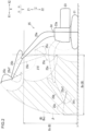
- the calculation part 50 acquires a dischargeable region B shown in FIG. 2 .
- the dischargeable region B is indicative of a dischargeable extent of the leading end attachment 25c (dischargeable extent ⁇ described below).
- the calculation part 50 stores the dischargeable region B in a memory in advance, or may calculate the dischargeable region B.
- the dischargeable extent of the leading end attachment 25c under the condition that the attachment 25 is operated but the lower travelling body 21 is not travelled is referred to as a dischargeable extent ⁇ .
- the dischargeable extent ⁇ has a three-dimensional shape in a substantially ring form (see FIGS. 2 and 3 ).
- the expression "the attachment 25 is operated" means, for example, at least one of the following operations [Example 1a] to [Example 1d].
- Example 1b Rotation of the arm 25b with respect to the boom 25a.
- Example 1c Rotation of the leading end attachment 25c with respect to the arm 25b.
- the dischargeable extent ⁇ is determined on the basis of information on the attachment 25. Specifically, the dischargeable extent ⁇ is determined on the basis of dimensions of each component of the attachment 25 (e.g., the boom 25a), and a possible range of an angle for each component of the attachment 25 (e.g., a range of an angle in which the boom 25a may be raised and lowered with respect to the upper slewing body 23).
- the calculation part 50 may calculate the dischargeable extent ⁇ , alternatively may not calculate it.
- positions at which the transport matter is not supposed to be discharged from the leading end attachment 25c may not be included in the dischargeable extent ⁇ .
- a position in the downward direction Z2 below an end of the lower travelling body 21 in the downward direction Z2 is not to be included, or alternatively may be included in the dischargeable extent ⁇ .
- a region in the rearward direction X2 behind an end portion of the lower travelling body 21 in the forward direction X1, where it is not possible (or is difficult) to locate the box bed 12 (see FIG. 1 ) may not be included in the dischargeable extent ⁇ .
- the leading end attachment 25c is a bucket
- rotation of the leading end attachment 25c with respect to the arm 25b causes the transport matter to be discharged from the leading end attachment 25c. Therefore, a region defined by a locus of the leading end attachment 25c for the discharge of the transport matter may not be included in the dischargeable extent ⁇ .
- the leading end attachment 25c is a device for nipping and gripping the transport matter, it is not necessary to rotate the leading end attachment 25c with respect to the arm 25b when discharging the transport matter.
- the dischargeable extent ⁇ may be within or may be substantially within a movable extent ⁇ 0 of a leading end portion of the leading end attachment 25c.
- the calculation part 50 acquires a dischargeable region Bx which is indicative of the dischargeable region B in the longitudinal directions X.
- the end (limit) of the dischargeable region Bx in the forward direction X1 is at a position of an end of the dischargeable extent ⁇ in the forward direction X1.
- the end of the dischargeable region Bx in the forward direction X1 is at the most forward position in the forward direction X1 in the dischargeable extent of the leading end attachment 25c under the condition that the attachment 25 is operated but the lower travelling body 21 is not travelled.
- the end of the dischargeable region Bx in the forward direction X1 is at, or may be off a position of the end of the dischargeable extent ⁇ in the forward direction X1. This is applied to relationships between the dischargeable region B and the dischargeable extent ⁇ which are described below.
- the end of the dischargeable region Bx in the rearward direction X2 is at a position of an end of the dischargeable extent ⁇ in the rearward direction X2.
- the calculation part 50 acquires a dischargeable region Bz in the vertical directions Z.
- the end of the dischargeable region Bz in the upward direction Z1 is at a position of an end of the dischargeable extent ⁇ in the upward direction Z1.
- the end of the dischargeable region Bz in the downward direction Z2 is at a position of an end of the dischargeable extent ⁇ in the downward direction Z2.
- the calculation part 50 acquires a dischargeable region Bxz in the longitudinal directions X and the vertical directions Z.
- the dischargeable region Bxz is an extent of the dischargeable extent ⁇ in the lateral directions Y.
- the dischargeable extent ⁇ has a three-dimensional shape equal to a locus formed by rotation of the dischargeable region Bxz shown in FIG. 2 around the slewing axis Zd of the upper slewing body 23.
- the dischargeable region Bxz includes a spatial extent around the slewing axis Zd.
- the calculation part 50 acquires a dischargeable region Bxy in the longitudinal directions X and the lateral directions Y.
- the dischargeable region Bxy is an extent of the dischargeable extent ⁇ in the vertical directions Z.
- the dischargeable region Bxy is an annular area defined by a circle B1 having the center at the slewing axis Zd of the upper slewing body 23 and a circle B1 having a larger diameter than the circle B1 and the center at the slewing axis Zd.
- the dischargeable region Bxy shown in FIG. 3 is a cross section of the dischargeable extent ⁇ shown in FIG. 2 at a position in the vertical directions Z, the cross section being parallel to a horizontal plane.
- the calculation part 50 acquires the dischargeable region B on the basis of the three-dimensional information.
- the dischargeable region B on the basis of the three-dimensional information is the same as the extent of the dischargeable extent ⁇ .
- the calculation part 50 acquires a preferable dischargeable region C.
- the preferable dischargeable region C is narrower than the dischargeable region B.
- the preferable dischargeable region C is determined on the basis of the operation efficiency of the attachment 25.
- the calculation part 50 stores in advance, or may calculate the preferable dischargeable region C.
- the preferable dischargeable region C is set, for example, as follows.
- the end (limit) of the preferable dischargeable region C in the forward direction X1 may be set at a position in the rearward direction X2 from the end of the dischargeable region B in the forward direction X1.
- the preferable dischargeable region C in the vertical directions Z is an annular area defined by a circle C1 having the center at the slewing axis Zd and by a circle C2 having a larger diameter than the circle C1 and the center at the slewing axis Zd.
- the diameter of the circle C1 is larger than that of the circle B1, and the diameter of the circle C2 is smaller than that of the circle B2, for the following reasons.
- [Reason 2a] A smaller distance from the slewing axis Zd of the upper slewing body 23 to the end of the leading end attachment 25c in the forward direction X1 (operation diameter) enables the working machine 20 to be stabilized, thereby ensuring the good operation efficiency.
- [Reason 2b] A smaller operation diameter enables the slewing acceleration of the upper slewing body 23 with respect to the lower travelling body 21 to be increased, thereby reducing the operation time and ensuring the good operation efficiency.
- [Reason 2c] A smaller operation diameter can reduce the energy necessary for the upper slewing body 23 to slew, thereby ensuring the good operation efficiency.
- the preferable dischargeable region C shown in FIG. 3 may be set in view of whether the transport matter can be carried efficiently by the leading end attachment 25c.
- Specific explanation is as follows. As shown in FIG. 2 , a plane passing through a base end portion and the leading end portion of the leading end attachment 25c serving as the bucket is assumed to be a plane 25cf. When the operation diameter is large (i.e., the maximum or substantially the maximum), the lengthwise direction of the arm 25b is horizontal or substantially horizontal. In this state, the plane 25cf on the leading end attachment 25c cannot be made to extend in the horizontal direction (or substantially the horizontal direction) even by expanding or contracting a cylinder (not shown) to rotate the leading end attachment 25c with respect to the arm 25b.
- the carriage amount of transport matter of the leading end attachment 25c can be seen to be limited.
- the operation diameter is smaller than the maximum or substantially the maximum, the plane 25cf of the leading end attachment 25c can be made to extend in the horizontal direction. Therefore, the carriage amount of transport matter of the leading end attachment 25c is not limited, thereby ensuring the good operation efficiency.
- the end (limit) of the preferable dischargeable region C in the rearward direction X2 may be set at a position in the forward direction X1 from the end of the dischargeable region B in the rearward direction X2 for the following reasons.
- Reason 3a When the operation diameter is larger than the minimum or substantially the minimum, there is not likelihood that the leading end attachment 25c comes into contact with the cab 23a, and a function of preventing the leading end attachment 25c from coming into contact with the cab 23a will work. Accordingly, the good operation efficiency can be assured. In the example shown in FIG. 2 , the leading end attachment 25c can be seen not to come into contact with the cab 23a.
- the calculation part 50 may acquire a preferable dischargeable region C in the longitudinal directions X (see FIG. 3 ) (similarly in the other directions).
- Preferable dischargeable regions C may be set in a plurality of steps (preferable extent, more preferable extent, still more preferable extent).
- the calculation part 50 determines whether at least a part of the box bed scope A shown in FIG. 3 falls within the dischargeable region B. For example, in the case that the transport vehicle position estimation is performed on the basis of the information in the longitudinal directions X, the calculation part 50 determines whether at least a part of the box bed scope Ax in the longitudinal directions X falls within the dischargeable region Bx in the longitudinal directions X. In the case that the transport vehicle position estimation is performed on the basis of the information in the vertical directions Z, the calculation part 50 determines whether at least a part of the box bed scope Az in the vertical directions Z falls within the dischargeable region Bz in the vertical directions Z.
- the calculation part 50 determines whether at least a part of the box bed scope Axz in the longitudinal directions X and the vertical directions Z falls within the dischargeable region Bxz in the longitudinal directions X and the vertical directions Z. In the case that the transport vehicle position estimation is performed on the basis of the information in the longitudinal directions X and the lateral directions Y, the calculation part 50 determines whether at least a part of the box bed scope Axy in the longitudinal directions X and the lateral directions Y falls within the dischargeable region Bxy in the longitudinal directions X and the lateral directions Y.
- the calculation part 50 determines whether at least a part of the box bed scope A in the longitudinal directions X, the lateral directions Y, and the vertical directions Z falls within the dischargeable region B in the longitudinal directions X, the lateral directions Y, and the vertical directions Z.
- the calculation part 50 determines whether at least a part of the box bed scope A falls within the preferable dischargeable region C.
- the calculation part 50 may determine whether the entire of the box bed scope A falls within the dischargeable region B.
- the calculation part 50 may determine whether the entire of the box bed scope A falls within the preferable dischargeable region C.
- the calculation part 50 outputs a signal according to the results of estimation.
- Signals output by the calculation part 50 can be used in various ways.
- a signal output by the calculation part 50 is used for a control, or may be used for a notification described below, or may include information indicative of a value.
- the calculation part 50 causes the first notification part 61 to generate a notification by outputting a signal to generate the notification when at least a part of the box bed scope A shown in FIG. 1 falls within the dischargeable region B.
- the calculation part 50 does not cause the first notification part 61 to generate a notification when the box bed scope A does not fall within the dischargeable region B.
- the first notification part 61 notifies that the transport vehicle 10 is located at a position to allow an operation of discharging the transport matter.
- the first notification part 61 generates a notification (a sign) to, for example, a driver in the transport vehicle 10.
- the notification of the first notification part 61 is at least one of sound, light, and vibration as described above.
- the first notification part 61 is a sound outputting part (e.g., a horn or a speaker) in at least one of the transport vehicle 10 and the working machine 20.
- the first notification part 61 may be a light outputting part (e.g., a screen or a light), or a vibration generating device with which the driver in the transport vehicle 10 comes into contact, provided in at least one of the transport vehicle 10 and the working machine 20.
- the calculation part 50 causes the second notification part 62 to generate a notification by outputting a signal to generate the notification when at least a part of the box bed scope A falls within the preferable dischargeable region C (see FIG. 3 ).
- the calculation part 50 does not cause the second notification part 62 to generate a notification when the box bed scope A does not fall within the preferable dischargeable region C (see FIG. 3 ).
- the second notification part 62 notifies that the transport vehicle 10 is located at a preferable position to allow the operation of discharging the transport matter.
- the second notification part 62 generates a notification (a sign) to, for example, the driver in the transport vehicle 10.
- the specific configuration of the notification of the second notification part 62 is similar to that of the first notification part 61.
- the notification of the second notification part 62 is different from that of the first notification part 61.
- the notification of the first notification part 61 and the notification of the second notification part 62 are different from each other in tones and contents of sound; colors, intensities, blinking patterns of light; or patterns of vibration.
- the calculation part 50 may cause the generation of the notification when the entire of the box bed scope A falls within the dischargeable region B.
- the calculation part 50 may cause the generation of the notification when the entire of the box bed scope A falls within the preferable dischargeable region C.
- the calculation part 50 may output information indicative of a distance necessary to move the transport vehicle 10 until the box bed scope A falls within the dischargeable region B (a remaining distance) when the box bed scope A does not fall within the dischargeable region B. Similarly, the calculation part 50 may output information indicative of a distance necessary to move the transport vehicle 10 until the box bed scope A falls within the preferable dischargeable region C (a remaining distance) when the box bed scope A does not fall within the preferable dischargeable region C.
- the information indicative of the remaining distance may be notified, for example, to the driver in the transport vehicle 10 by sound or indication (the same is applied to the following information indicative of a moving direction).
- the calculation part 50 may output information indicative of a moving direction of the transport vehicle 10 to make the box bed scope A fall within the dischargeable region B when the box bed scope A does not fall within the dischargeable region B (the same is applied to the preferable dischargeable region C). Specifically, the calculation part 50 calculates and outputs an angle ⁇ shown in FIG. 3 on the basis of the distance image acquired by the distance image acquiring part 40.
- the angle ⁇ is an angle (inclination) of the flat face part 13 of the box bed 12 with respect to the upper slewing body 23 (working machine 20). In other words, the angle ⁇ is, for example, an angle between the longitudinal directions X and the flat face part 13.
- the angle ⁇ is an angle between the longitudinal directions X and the closest surface of the flat face part 13 of the box bed 12 (e.g., the rear surface 13b in FIG. 3 ) to the upper slewing body 23.
- the calculation part 50 may calculate and output information indicative of the angle ⁇ when the box bed scope A falls within the dischargeable region B (the same is applied to the preferable dischargeable region C).
- the calculation part 50 may output a signal indicating that the box bed scope A falls within the dischargeable region B when at least a part of the box bed scope A falls within the dischargeable region B (the same is applied to the preferable dischargeable region C).
- the calculation part 50 may output a signal for a purpose other than the notification by the first notification part 61 and the second notification part 62.
- the operator can determine whether the transport vehicle 10 is at a position to allow the operation of discharging the transport matter. In this case, the operator can send a notification (specifically, a sign to stop) to the driver in the transport vehicle 10 when the transport vehicle 10 reaches a position to allow the operation of discharging the transport matter.
- the working machine 20 is automatically controlled, the determination by the operator as described above is not available. In this case, it is desirable to automatically determine whether the transport vehicle 10 is at a position to allow the operation of discharging the transport matter.
- the working machine 20 is remotely controlled, the operator controls the working machine 20 while looking at a screen.
- the transport vehicle position estimating device 30 in this embodiment can automatically determine whether the transport vehicle 10 is at a position to allow the operation of discharging the transport matter.
- a transport vehicle position estimating device is used in a working machine having an attachment.
- the attachment is configured to carry and discharge a load of matter to a box bed provided on a transport vehicle.
- the transport vehicle position estimating device includes a distance image acquiring part and a calculation part.
- the distance image acquiring part acquires a distance image of a box bed.
- the calculation part sets a box bed scope indicative of a positional extent of the box bed on the basis of the distance image of the box bed acquired by the distance image acquiring part.
- the calculation part acquires a dischargeable region indicative of a dischargeable extent of the attachment.
- the calculation part determines whether at least a part of the box bed scope falls within the dischargeable region.
- the calculation part automatically determines whether at least a part of the box bed scope A of the transport vehicle falls within the dischargeable region of the working machine.
- the calculation part can automatically determine whether the transport vehicle is located at such a position that the box bed scope falls within the dischargeable region.
- the box bed scope is set on the basis of the distance image of the box bed. Accordingly, even when the box bed is changed, a box bed scope of the changed box bed is set on the basis of a distance image thereof. Therefore, even when the kind of transport vehicle is changed, it can be automatically determined whether the box bed scope falls within the dischargeable region. Accordingly, the position of the transport vehicle with respect to the working machine can be estimated even when the kind of transport vehicle is changed.
- the working machine includes a lower travelling body and an upper slewing body capable of slewing with respect to the lower travelling body.
- the calculation part sets the dischargeable region in at least a part of a space in a longitudinal direction of the upper slewing body between a surface farthest from the upper slewing body and a surface closest to the upper slewing body among the plurality of surfaces of the box bed when the upper slewing body is in a specific posture.
- the specific posture renders the longitudinal direction perpendicularly intersecting one of the plurality of surfaces.
- the box bed scope is set, for example, in at least a part of a space between two surfaces (e.g., a rear surface 13b and a front surface 13d) on the opposite ends in the longitudinal directions.
- the box bed scope can be set in a preferable region on the basis of the position of the box bed. Accordingly, the transport matter can be loaded to the box bed by the attachment more reliably when it is determined that the box bed scope falls within the dischargeable region.
- the box bed scope is set in at least a part of a space above the box bed.
- the box bed scope is set in at least a part of a space above the box bed.
- the box bed scope can be set in a preferable region on the basis of the position of the box bed. Accordingly, the transport matter can be loaded to the box bed by the attachment more reliably when it is determined that the box bed scope falls within the dischargeable region.
- the box bed scope is set in at least a part of an area overlapping the box bed in a plan view.
- the box bed scope is set in at least a part of an area overlapping the box bed in a plan view.
- the box bed scope can be set in a preferable region on the basis of the position of the box bed. Accordingly, the transport matter can be loaded to the box bed by the attachment more reliably when it is determined that the box bed scope falls within the dischargeable region.
- the transport vehicle position estimating device further includes a first notification part for generating a notification of at least one of sound, light, and vibration.
- the calculation part causes the first notification part to generate the notification when at least a part of the box bed scope falls within the dischargeable region.
- This configuration enables to notify a person (e.g., a driver in the transport vehicle) that at least a part of the box bed scope falls within the dischargeable region.
- the calculation part outputs information indicative of a movement distance of the transport vehicle until at least a part of the box bed scope falls within the dischargeable region when the box bed scope is out of the dischargeable region.
- This configuration of outputting information indicative of a movement distance of the transport vehicle until at least a part of the box bed scope falls within the dischargeable region enables to transmit information on a remaining distance to a person (e.g., a driver in the transport vehicle) or a computer.
- the calculation part acquires a preferable dischargeable region narrower than the dischargeable region and determines whether at least a part of the box bed scope A falls within the preferable dischargeable region.
- the preferable dischargeable region is determined on the basis of efficiency of an operation (hereinafter, simply referred to as "operation") by the attachment.
- operation an operation
- the preferable dischargeable region is set such that the operation has a better efficiency when performing within the preferable dischargeable region than when performing out of the preferable dischargeable region. Accordingly, the operation efficiency can be improved when the operation is performed within the preferable dischargeable region.
- the transport vehicle position estimating device further includes a second notification part for generating a notification of at least one of sound, light, and vibration.
- the calculation part causes the second notification part to generate the notification when at least a part of the box bed scope falls within the preferable dischargeable region.
- This configuration enables to notify a person (e.g., a driver in the transport vehicle) that at least a part of the box bed scope falls within the preferable dischargeable region.
- the calculation part outputs information indicative of a movement distance of the transport vehicle 10 until the box bed scope falls within the preferable dischargeable region when the box bed scope is out of the preferable dischargeable scope.
- This configuration of outputting information indicative of a movement distance of the transport vehicle until the box bed scope falls within the preferable dischargeable region enables to transmit information on a remaining distance to a person (e.g., a driver in the transport vehicle) or a computer.
- the calculation part calculates and outputs an angle of a flat face part of the box bed to the working machine on the basis of the distance image acquired by the distance image acquiring part.
- This configuration of outputting the angle enables to transmit an angle to a person (e.g., a driver in the transport vehicle) or a computer.
- the calculation part determines that the box bed scope falls within the dischargeable region when at least a longitudinal directional part of the box bed scope falls within a longitudinal directional part of the dischargeable region.
- This configuration enables determination as to whether at least a part of the box bed scope falls within the dischargeable region by observing the longitudinal directions.
- the calculation part determines that the box bed scope falls within the dischargeable region when at least a vertical directional part of the box bed scope falls within a vertical directional part of the dischargeable region.
- This configuration enables determination as to whether at least a part of the box bed scope falls within the dischargeable region by observing the vertical directions.
- the calculation part determines that the box bed scope falls within the dischargeable region when at least a longitudinal directional and lateral directional part of the box bed scope falls within a longitudinal directional and lateral directional part of the dischargeable region.
- This configuration enables determination as to whether at least a part of the box bed scope falls within the dischargeable region by observing the longitudinal directions and vertical directions.
- the embodiment described above may include various modifications.
- the disposition and the shape of each component in the embodiment may be changed.
- the number of components may be changed, or alternatively some components may be omitted.
- Components described as members or parts different from each other may be combined into one member or one part.
- a component described as a member or a part may be separately provided as members or parts different from each other.
- the box bed space ⁇ and the box bed scope A may be a predetermined region or extent with respect to the box bed 12, but this predetermined region or extent may be changed manually, or changed automatically according to a condition (the same is applied to the dischargeable extent ⁇ , the dischargeable region B, and the preferable dischargeable region.
- the scope of the invention is defined by the appended claims.
Landscapes
- Engineering & Computer Science (AREA)
- Mining & Mineral Resources (AREA)
- Structural Engineering (AREA)
- General Engineering & Computer Science (AREA)
- Civil Engineering (AREA)
- Physics & Mathematics (AREA)
- Electromagnetism (AREA)
- Mechanical Engineering (AREA)
- General Physics & Mathematics (AREA)
- Remote Sensing (AREA)
- Radar, Positioning & Navigation (AREA)
- Computer Networks & Wireless Communication (AREA)
- Aviation & Aerospace Engineering (AREA)
- Component Parts Of Construction Machinery (AREA)
- Control Of Position, Course, Altitude, Or Attitude Of Moving Bodies (AREA)
Claims (13)
- Dispositif d'estimation de position de véhicule de transport (30) destiné à être utilisé dans un engin de chantier (20) comportant un équipement (25) permettant de transporter et de décharger une charge de matière sur une plateforme de chargement (12) installée sur un véhicule de transport (10), le dispositif comprenant :une partie d'acquisition d'image de distance (40) configurée pour acquérir une image de distance de la plateforme de chargement (12) ; etune partie de calcul (50),le dispositif étant caractérisé en ce que la partie de calcul (50) est configurée pour :définir une portée de plateforme de chargement (A) indiquant une étendue dimensionnelle de la plateforme de chargement (12) sur la base de l'image de distance de la plateforme de chargement (12) acquise par la partie d'acquisition d'image de distance (40),acquérir une région déchargeable (B) indiquant une étendue déchargeable de l'équipement (25), etdéterminer si au moins une partie de la portée de plateforme de chargement (A) se trouve dans la région déchargeable (B).
- Dispositif d'estimation de position de véhicule de transport (30) selon la revendication 1, dans lequel :
l'engin de chantier (20) comprend :un corps mobile inférieur (21) ; etun corps pivotant supérieur (23) capable de pivoter par rapport au corps mobile inférieur (21),la plateforme de chargement (12) comporte une surface inférieure (13a) et une pluralité de surfaces (13b, 13c, 13d) entourant la surface inférieure (13a),la partie de calcul (50) définit la région déchargeable (B) dans au moins une partie d'un espace dans une direction longitudinale du corps pivotant supérieur (23) entre une surface la plus éloignée du corps pivotant supérieur (23) et une surface la plus proche du corps pivotant supérieur (23) parmi la pluralité de surfaces de la plateforme de chargement (12) lorsque le corps pivotant supérieur (23) est dans une posture spécifique, etla position spécifique fait en sorte que la direction longitudinale coupe perpendiculairement l'une de la pluralité de surfaces. - Dispositif d'estimation de position de véhicule de transport (30) selon la revendication 1 ou 2, dans lequel :
la portée de plateforme de chargement (A) est définie dans au moins une partie d'un espace au-dessus de la plateforme de chargement (12). - Dispositif d'estimation de position de véhicule de transport (30) selon l'une quelconque des revendications 1 à 3, dans lequel :
la portée de plateforme de chargement (A) est définie dans au moins une partie d'une zone chevauchant la plateforme de chargement (12) dans une vue en plan. - Dispositif d'estimation de position de véhicule de transport (30) selon l'une quelconque des revendications 1 à 4, comprenant en outre une première partie de notification (61) pour générer une notification d'un son et/ou d'une lumière et/ou d'une vibration,
la partie de calcul (50) amenant la première partie notification (61) à générer la notification lorsque au moins une partie de la portée de plateforme de chargement (A) se trouve dans la région déchargeable (B). - Dispositif d'estimation de position de véhicule de transport (30) selon l'une quelconque des revendications 1 à 5, dans lequel :
la partie de calcul (50) délivre en sortie des informations indiquant une distance de déplacement du véhicule de transport (10) jusqu'à ce qu'au moins une partie de la portée de plateforme de chargement (A) se trouve dans la région déchargeable (B) lorsque la portée de plateforme de chargement (A) est hors de la région déchargeable (B). - Dispositif d'estimation de position de véhicule de transport (30) selon l'une quelconque des revendications 1 à 6, dans lequel :la partie de calcul (50) acquiert une région déchargeable préférable (C) plus étroite que la région déchargeable (B), etdétermine si au moins une partie de la portée de plateforme de chargement (A) se trouve dans la région déchargeable préférable (C).
- Dispositif d'estimation de position de véhicule de transport (30) selon la revendication 7, comprenant en outre une seconde partie de notification (62) pour générer une notification d'un son et/ou d'une lumière et/ou d'une vibration,
la partie de calcul (50) amenant la seconde partie notification (62) à générer la notification lorsque au moins une partie de la portée de plateforme de chargement (A) se trouve dans la région déchargeable préférable (C). - Dispositif d'estimation de position de véhicule de transport (30) selon la revendication 7 ou 8, dans lequel :
la partie de calcul (50) délivre en sortie des informations indiquant une distance de déplacement du véhicule de transport (10) jusqu'à ce que la portée de plateforme de chargement (A) se trouve dans la région déchargeable préférable (C) lorsque la portée de plateforme de chargement (A) est hors de la région déchargeable préférable (C). - Dispositif d'estimation de position de véhicule de transport (30) selon l'une quelconque des revendications 1 à 9, dans lequel :
la partie de calcul (50) calcule et délivre en sortie un angle (θ) d'une surface de la plateforme de chargement (12) vers l'engin de chantier (20) sur la base de l'image de distance acquise par la partie d'acquisition d'image de distance (40). - Dispositif d'estimation de position de véhicule de transport (30) selon la revendication 2, dans lequel :
la partie de calcul (50) détermine que la portée de plateforme de chargement (A) se trouve dans la région déchargeable (B) lorsque au moins une partie directionnelle longitudinale de la portée de plateforme de chargement (A) se trouve dans une partie directionnelle longitudinale de la région déchargeable (B). - Dispositif d'estimation de position de véhicule de transport (30) selon la revendication 3, dans lequel :
la partie de calcul (50) détermine que la portée de plateforme de chargement (A) se trouve dans la région déchargeable (B) lorsque au moins une partie directionnelle verticale de la portée de plateforme de chargement (A) se trouve dans une partie directionnelle verticale de la région déchargeable (B). - Dispositif d'estimation de position de véhicule de transport (30) selon la revendication 4, dans lequel :la partie de calcul (50) détermine que la portée de plateforme de chargement (A) se trouve dans la région déchargeable (B) lorsque au moins une partie directionnelle longitudinale etdirectionnelle latérale de la portée de plateforme de chargement (A) se trouve dans une partie directionnelle longitudinale et directionnelle latérale de la région déchargeable (B).
Applications Claiming Priority (2)
| Application Number | Priority Date | Filing Date | Title |
|---|---|---|---|
| JP2019176036A JP7306191B2 (ja) | 2019-09-26 | 2019-09-26 | 輸送車位置判定装置 |
| PCT/JP2020/026364 WO2021059658A1 (fr) | 2019-09-26 | 2020-07-06 | Dispositif pour évaluer la position d'un véhicule de transport |
Publications (3)
| Publication Number | Publication Date |
|---|---|
| EP4023823A1 EP4023823A1 (fr) | 2022-07-06 |
| EP4023823A4 EP4023823A4 (fr) | 2022-11-16 |
| EP4023823B1 true EP4023823B1 (fr) | 2023-09-06 |
Family
ID=75166035
Family Applications (1)
| Application Number | Title | Priority Date | Filing Date |
|---|---|---|---|
| EP20869069.3A Active EP4023823B1 (fr) | 2019-09-26 | 2020-07-06 | Dispositif pour évaluer la position d'un véhicule de transport |
Country Status (5)
| Country | Link |
|---|---|
| US (1) | US12441562B2 (fr) |
| EP (1) | EP4023823B1 (fr) |
| JP (1) | JP7306191B2 (fr) |
| CN (1) | CN114450453B (fr) |
| WO (1) | WO2021059658A1 (fr) |
Families Citing this family (7)
| Publication number | Priority date | Publication date | Assignee | Title |
|---|---|---|---|---|
| JP7602741B2 (ja) * | 2020-05-25 | 2024-12-19 | 住友建機株式会社 | ショベル用のシステム |
| JP7484623B2 (ja) * | 2020-09-25 | 2024-05-16 | コベルコ建機株式会社 | 停止指示システム |
| DE102021206027A1 (de) * | 2021-06-14 | 2022-12-15 | Robert Bosch Gesellschaft mit beschränkter Haftung | Verfahren zum Unterstützen eines Fahrzeugführers eines Transportfahrzeugs beim Einnehmen einer Ladeposition |
| JP7582104B2 (ja) * | 2021-07-13 | 2024-11-13 | コベルコ建機株式会社 | 異常動作検出システム |
| JP7714978B2 (ja) * | 2021-09-24 | 2025-07-30 | コベルコ建機株式会社 | 車両判別システム |
| JP2024004776A (ja) * | 2022-06-29 | 2024-01-17 | 日立建機株式会社 | 作業機械 |
| JP2026000069A (ja) * | 2024-06-17 | 2026-01-05 | 株式会社小松製作所 | 遠隔操作支援システム、作業車両の遠隔操作装置、および遠隔操作支援方法 |
Family Cites Families (16)
| Publication number | Priority date | Publication date | Assignee | Title |
|---|---|---|---|---|
| JP2922727B2 (ja) | 1992-07-01 | 1999-07-26 | 株式会社フジタ | 土砂運搬車の走行制御システム |
| JP3789218B2 (ja) * | 1997-10-22 | 2006-06-21 | 日立建機株式会社 | 自動運転建設機械およびその運転方法 |
| JP2000192514A (ja) | 1998-12-28 | 2000-07-11 | Hitachi Constr Mach Co Ltd | 自動運転建設機械およびその運転方法 |
| JP3787046B2 (ja) | 1999-09-17 | 2006-06-21 | 日立建機株式会社 | 油圧ショベルの作業量モニタ装置 |
| US9598836B2 (en) | 2012-03-29 | 2017-03-21 | Harnischfeger Technologies, Inc. | Overhead view system for a shovel |
| JP5529241B2 (ja) | 2012-11-20 | 2014-06-25 | 株式会社小松製作所 | 作業機械および作業機械の作業量計測方法 |
| CA2923683C (fr) * | 2013-12-12 | 2018-03-13 | Hitachi Construction Machinery Co., Ltd. | Systeme de deplacement de vehicule et procede de commande de deplacement de vehicule |
| US9523180B2 (en) * | 2014-04-28 | 2016-12-20 | Deere & Company | Semi-automatic material loading |
| US9464913B2 (en) * | 2015-02-16 | 2016-10-11 | Jaybridge Robotics, Inc. | Assistive vehicular guidance system and method |
| US10815640B2 (en) | 2016-08-31 | 2020-10-27 | Komatsu Ltd. | Wheel loader and method for controlling wheel loader |
| JP6898816B2 (ja) | 2017-09-15 | 2021-07-07 | 株式会社小松製作所 | 表示システム、表示方法、及び表示装置 |
| JP6927821B2 (ja) | 2017-09-15 | 2021-09-01 | 株式会社小松製作所 | 表示システム、及び表示装置 |
| CN111919003A (zh) * | 2018-03-26 | 2020-11-10 | 住友建机株式会社 | 挖土机 |
| US20210064050A1 (en) * | 2019-08-30 | 2021-03-04 | Deere & Company | Methods and apparatus to record and execute mission plan |
| US20220167543A1 (en) * | 2020-12-02 | 2022-06-02 | Cnh Industrial America Llc | System and method for implementing end-of-row turns with agricultural vehicles |
| US11874665B2 (en) * | 2021-05-24 | 2024-01-16 | Trimble Inc. | Area coverage planner with replenishment planner |
-
2019
- 2019-09-26 JP JP2019176036A patent/JP7306191B2/ja active Active
-
2020
- 2020-07-06 US US17/763,092 patent/US12441562B2/en active Active
- 2020-07-06 WO PCT/JP2020/026364 patent/WO2021059658A1/fr not_active Ceased
- 2020-07-06 EP EP20869069.3A patent/EP4023823B1/fr active Active
- 2020-07-06 CN CN202080066937.2A patent/CN114450453B/zh active Active
Also Published As
| Publication number | Publication date |
|---|---|
| US20220388791A1 (en) | 2022-12-08 |
| WO2021059658A1 (fr) | 2021-04-01 |
| CN114450453A (zh) | 2022-05-06 |
| JP2021055256A (ja) | 2021-04-08 |
| EP4023823A1 (fr) | 2022-07-06 |
| EP4023823A4 (fr) | 2022-11-16 |
| US12441562B2 (en) | 2025-10-14 |
| JP7306191B2 (ja) | 2023-07-11 |
| CN114450453B (zh) | 2024-02-06 |
Similar Documents
| Publication | Publication Date | Title |
|---|---|---|
| EP4023823B1 (fr) | Dispositif pour évaluer la position d'un véhicule de transport | |
| JP7689159B2 (ja) | 作業システム、制御方法および積込機械制御装置 | |
| US12094151B2 (en) | Image processing system, image processing method, learned model generation method, and data set for learning | |
| JP6243926B2 (ja) | 車両走行システム、搬送車の停車姿勢設定装置が実行する方法、及び搬送車の停車姿勢設定装置 | |
| US12088968B2 (en) | Display control device, display control system, and display control method | |
| CN115298632B (zh) | 作业机械 | |
| JP7080750B2 (ja) | 表示制御システム、遠隔操作システム、表示制御装置、および表示制御方法 | |
| US12312774B2 (en) | Excavation information processing device, work machine, excavation support device, and excavation information processing method | |
| US11634889B2 (en) | Control device and control method | |
| JP7484630B2 (ja) | 積込ポイント決定システム | |
| JP7636598B2 (ja) | 表示制御装置及び表示方法 | |
| KR20230003025A (ko) | 작업 시스템 및 제어 방법 | |
| JP7390991B2 (ja) | 作業機械および施工支援システム | |
| JP7175680B2 (ja) | 表示制御装置、表示制御システム、および表示制御方法 | |
| EP4390301A1 (fr) | Système de détermination de véhicule | |
| AU2021352215B2 (en) | Display control device and display control method | |
| JP7569351B2 (ja) | 作業機械 | |
| JP2025118265A (ja) | 識別システム及び識別方法 | |
| JP2024004776A (ja) | 作業機械 |
Legal Events
| Date | Code | Title | Description |
|---|---|---|---|
| STAA | Information on the status of an ep patent application or granted ep patent |
Free format text: STATUS: THE INTERNATIONAL PUBLICATION HAS BEEN MADE |
|
| PUAI | Public reference made under article 153(3) epc to a published international application that has entered the european phase |
Free format text: ORIGINAL CODE: 0009012 |
|
| STAA | Information on the status of an ep patent application or granted ep patent |
Free format text: STATUS: REQUEST FOR EXAMINATION WAS MADE |
|
| 17P | Request for examination filed |
Effective date: 20220328 |
|
| AK | Designated contracting states |
Kind code of ref document: A1 Designated state(s): AL AT BE BG CH CY CZ DE DK EE ES FI FR GB GR HR HU IE IS IT LI LT LU LV MC MK MT NL NO PL PT RO RS SE SI SK SM TR |
|
| A4 | Supplementary search report drawn up and despatched |
Effective date: 20221014 |
|
| RIC1 | Information provided on ipc code assigned before grant |
Ipc: E02F 9/20 20060101ALI20221010BHEP Ipc: E02F 3/43 20060101ALI20221010BHEP Ipc: G01G 19/08 20060101ALI20221010BHEP Ipc: B60P 1/04 20060101ALI20221010BHEP Ipc: E02F 9/26 20060101AFI20221010BHEP |
|
| DAV | Request for validation of the european patent (deleted) | ||
| DAX | Request for extension of the european patent (deleted) | ||
| GRAP | Despatch of communication of intention to grant a patent |
Free format text: ORIGINAL CODE: EPIDOSNIGR1 |
|
| STAA | Information on the status of an ep patent application or granted ep patent |
Free format text: STATUS: GRANT OF PATENT IS INTENDED |
|
| INTG | Intention to grant announced |
Effective date: 20230411 |
|
| GRAS | Grant fee paid |
Free format text: ORIGINAL CODE: EPIDOSNIGR3 |
|
| GRAA | (expected) grant |
Free format text: ORIGINAL CODE: 0009210 |
|
| STAA | Information on the status of an ep patent application or granted ep patent |
Free format text: STATUS: THE PATENT HAS BEEN GRANTED |
|
| AK | Designated contracting states |
Kind code of ref document: B1 Designated state(s): AL AT BE BG CH CY CZ DE DK EE ES FI FR GB GR HR HU IE IS IT LI LT LU LV MC MK MT NL NO PL PT RO RS SE SI SK SM TR |
|
| REG | Reference to a national code |
Ref country code: GB Ref legal event code: FG4D |
|
| REG | Reference to a national code |
Ref country code: CH Ref legal event code: EP |
|
| REG | Reference to a national code |
Ref country code: IE Ref legal event code: FG4D |
|
| REG | Reference to a national code |
Ref country code: DE Ref legal event code: R096 Ref document number: 602020017438 Country of ref document: DE |
|
| REG | Reference to a national code |
Ref country code: LT Ref legal event code: MG9D |
|
| REG | Reference to a national code |
Ref country code: NL Ref legal event code: MP Effective date: 20230906 |
|
| PG25 | Lapsed in a contracting state [announced via postgrant information from national office to epo] |
Ref country code: GR Free format text: LAPSE BECAUSE OF FAILURE TO SUBMIT A TRANSLATION OF THE DESCRIPTION OR TO PAY THE FEE WITHIN THE PRESCRIBED TIME-LIMIT Effective date: 20231207 |
|
| PG25 | Lapsed in a contracting state [announced via postgrant information from national office to epo] |
Ref country code: SE Free format text: LAPSE BECAUSE OF FAILURE TO SUBMIT A TRANSLATION OF THE DESCRIPTION OR TO PAY THE FEE WITHIN THE PRESCRIBED TIME-LIMIT Effective date: 20230906 Ref country code: RS Free format text: LAPSE BECAUSE OF FAILURE TO SUBMIT A TRANSLATION OF THE DESCRIPTION OR TO PAY THE FEE WITHIN THE PRESCRIBED TIME-LIMIT Effective date: 20230906 Ref country code: NO Free format text: LAPSE BECAUSE OF FAILURE TO SUBMIT A TRANSLATION OF THE DESCRIPTION OR TO PAY THE FEE WITHIN THE PRESCRIBED TIME-LIMIT Effective date: 20231206 Ref country code: LV Free format text: LAPSE BECAUSE OF FAILURE TO SUBMIT A TRANSLATION OF THE DESCRIPTION OR TO PAY THE FEE WITHIN THE PRESCRIBED TIME-LIMIT Effective date: 20230906 Ref country code: LT Free format text: LAPSE BECAUSE OF FAILURE TO SUBMIT A TRANSLATION OF THE DESCRIPTION OR TO PAY THE FEE WITHIN THE PRESCRIBED TIME-LIMIT Effective date: 20230906 Ref country code: HR Free format text: LAPSE BECAUSE OF FAILURE TO SUBMIT A TRANSLATION OF THE DESCRIPTION OR TO PAY THE FEE WITHIN THE PRESCRIBED TIME-LIMIT Effective date: 20230906 Ref country code: GR Free format text: LAPSE BECAUSE OF FAILURE TO SUBMIT A TRANSLATION OF THE DESCRIPTION OR TO PAY THE FEE WITHIN THE PRESCRIBED TIME-LIMIT Effective date: 20231207 Ref country code: FI Free format text: LAPSE BECAUSE OF FAILURE TO SUBMIT A TRANSLATION OF THE DESCRIPTION OR TO PAY THE FEE WITHIN THE PRESCRIBED TIME-LIMIT Effective date: 20230906 |
|
| REG | Reference to a national code |
Ref country code: AT Ref legal event code: MK05 Ref document number: 1608734 Country of ref document: AT Kind code of ref document: T Effective date: 20230906 |
|
| PG25 | Lapsed in a contracting state [announced via postgrant information from national office to epo] |
Ref country code: NL Free format text: LAPSE BECAUSE OF FAILURE TO SUBMIT A TRANSLATION OF THE DESCRIPTION OR TO PAY THE FEE WITHIN THE PRESCRIBED TIME-LIMIT Effective date: 20230906 |
|
| PG25 | Lapsed in a contracting state [announced via postgrant information from national office to epo] |
Ref country code: IS Free format text: LAPSE BECAUSE OF FAILURE TO SUBMIT A TRANSLATION OF THE DESCRIPTION OR TO PAY THE FEE WITHIN THE PRESCRIBED TIME-LIMIT Effective date: 20240106 |
|
| PG25 | Lapsed in a contracting state [announced via postgrant information from national office to epo] |
Ref country code: AT Free format text: LAPSE BECAUSE OF FAILURE TO SUBMIT A TRANSLATION OF THE DESCRIPTION OR TO PAY THE FEE WITHIN THE PRESCRIBED TIME-LIMIT Effective date: 20230906 |
|
| PG25 | Lapsed in a contracting state [announced via postgrant information from national office to epo] |
Ref country code: ES Free format text: LAPSE BECAUSE OF FAILURE TO SUBMIT A TRANSLATION OF THE DESCRIPTION OR TO PAY THE FEE WITHIN THE PRESCRIBED TIME-LIMIT Effective date: 20230906 |
|
| PG25 | Lapsed in a contracting state [announced via postgrant information from national office to epo] |
Ref country code: SM Free format text: LAPSE BECAUSE OF FAILURE TO SUBMIT A TRANSLATION OF THE DESCRIPTION OR TO PAY THE FEE WITHIN THE PRESCRIBED TIME-LIMIT Effective date: 20230906 Ref country code: RO Free format text: LAPSE BECAUSE OF FAILURE TO SUBMIT A TRANSLATION OF THE DESCRIPTION OR TO PAY THE FEE WITHIN THE PRESCRIBED TIME-LIMIT Effective date: 20230906 Ref country code: IS Free format text: LAPSE BECAUSE OF FAILURE TO SUBMIT A TRANSLATION OF THE DESCRIPTION OR TO PAY THE FEE WITHIN THE PRESCRIBED TIME-LIMIT Effective date: 20240106 Ref country code: ES Free format text: LAPSE BECAUSE OF FAILURE TO SUBMIT A TRANSLATION OF THE DESCRIPTION OR TO PAY THE FEE WITHIN THE PRESCRIBED TIME-LIMIT Effective date: 20230906 Ref country code: EE Free format text: LAPSE BECAUSE OF FAILURE TO SUBMIT A TRANSLATION OF THE DESCRIPTION OR TO PAY THE FEE WITHIN THE PRESCRIBED TIME-LIMIT Effective date: 20230906 Ref country code: CZ Free format text: LAPSE BECAUSE OF FAILURE TO SUBMIT A TRANSLATION OF THE DESCRIPTION OR TO PAY THE FEE WITHIN THE PRESCRIBED TIME-LIMIT Effective date: 20230906 Ref country code: AT Free format text: LAPSE BECAUSE OF FAILURE TO SUBMIT A TRANSLATION OF THE DESCRIPTION OR TO PAY THE FEE WITHIN THE PRESCRIBED TIME-LIMIT Effective date: 20230906 Ref country code: SK Free format text: LAPSE BECAUSE OF FAILURE TO SUBMIT A TRANSLATION OF THE DESCRIPTION OR TO PAY THE FEE WITHIN THE PRESCRIBED TIME-LIMIT Effective date: 20230906 Ref country code: PT Free format text: LAPSE BECAUSE OF FAILURE TO SUBMIT A TRANSLATION OF THE DESCRIPTION OR TO PAY THE FEE WITHIN THE PRESCRIBED TIME-LIMIT Effective date: 20240108 |
|
| PG25 | Lapsed in a contracting state [announced via postgrant information from national office to epo] |
Ref country code: PL Free format text: LAPSE BECAUSE OF FAILURE TO SUBMIT A TRANSLATION OF THE DESCRIPTION OR TO PAY THE FEE WITHIN THE PRESCRIBED TIME-LIMIT Effective date: 20230906 |
|
| REG | Reference to a national code |
Ref country code: DE Ref legal event code: R097 Ref document number: 602020017438 Country of ref document: DE |
|
| PG25 | Lapsed in a contracting state [announced via postgrant information from national office to epo] |
Ref country code: DK Free format text: LAPSE BECAUSE OF FAILURE TO SUBMIT A TRANSLATION OF THE DESCRIPTION OR TO PAY THE FEE WITHIN THE PRESCRIBED TIME-LIMIT Effective date: 20230906 |
|
| PLBE | No opposition filed within time limit |
Free format text: ORIGINAL CODE: 0009261 |
|
| STAA | Information on the status of an ep patent application or granted ep patent |
Free format text: STATUS: NO OPPOSITION FILED WITHIN TIME LIMIT |
|
| PG25 | Lapsed in a contracting state [announced via postgrant information from national office to epo] |
Ref country code: DK Free format text: LAPSE BECAUSE OF FAILURE TO SUBMIT A TRANSLATION OF THE DESCRIPTION OR TO PAY THE FEE WITHIN THE PRESCRIBED TIME-LIMIT Effective date: 20230906 Ref country code: SI Free format text: LAPSE BECAUSE OF FAILURE TO SUBMIT A TRANSLATION OF THE DESCRIPTION OR TO PAY THE FEE WITHIN THE PRESCRIBED TIME-LIMIT Effective date: 20230906 |
|
| 26N | No opposition filed |
Effective date: 20240607 |
|
| PG25 | Lapsed in a contracting state [announced via postgrant information from national office to epo] |
Ref country code: BG Free format text: LAPSE BECAUSE OF FAILURE TO SUBMIT A TRANSLATION OF THE DESCRIPTION OR TO PAY THE FEE WITHIN THE PRESCRIBED TIME-LIMIT Effective date: 20230906 |
|
| PG25 | Lapsed in a contracting state [announced via postgrant information from national office to epo] |
Ref country code: BG Free format text: LAPSE BECAUSE OF FAILURE TO SUBMIT A TRANSLATION OF THE DESCRIPTION OR TO PAY THE FEE WITHIN THE PRESCRIBED TIME-LIMIT Effective date: 20230906 |
|
| PG25 | Lapsed in a contracting state [announced via postgrant information from national office to epo] |
Ref country code: MC Free format text: LAPSE BECAUSE OF FAILURE TO SUBMIT A TRANSLATION OF THE DESCRIPTION OR TO PAY THE FEE WITHIN THE PRESCRIBED TIME-LIMIT Effective date: 20230906 |
|
| REG | Reference to a national code |
Ref country code: CH Ref legal event code: PL |
|
| PG25 | Lapsed in a contracting state [announced via postgrant information from national office to epo] |
Ref country code: LU Free format text: LAPSE BECAUSE OF NON-PAYMENT OF DUE FEES Effective date: 20240706 |
|
| PG25 | Lapsed in a contracting state [announced via postgrant information from national office to epo] |
Ref country code: LU Free format text: LAPSE BECAUSE OF NON-PAYMENT OF DUE FEES Effective date: 20240706 |
|
| PG25 | Lapsed in a contracting state [announced via postgrant information from national office to epo] |
Ref country code: BE Free format text: LAPSE BECAUSE OF NON-PAYMENT OF DUE FEES Effective date: 20240731 Ref country code: CH Free format text: LAPSE BECAUSE OF NON-PAYMENT OF DUE FEES Effective date: 20240731 |
|
| REG | Reference to a national code |
Ref country code: BE Ref legal event code: MM Effective date: 20240731 |
|
| PGFP | Annual fee paid to national office [announced via postgrant information from national office to epo] |
Ref country code: GB Payment date: 20250529 Year of fee payment: 6 |
|
| PG25 | Lapsed in a contracting state [announced via postgrant information from national office to epo] |
Ref country code: IT Free format text: LAPSE BECAUSE OF NON-PAYMENT OF DUE FEES Effective date: 20240706 |
|
| PGFP | Annual fee paid to national office [announced via postgrant information from national office to epo] |
Ref country code: FR Payment date: 20250610 Year of fee payment: 6 |
|
| PG25 | Lapsed in a contracting state [announced via postgrant information from national office to epo] |
Ref country code: IE Free format text: LAPSE BECAUSE OF NON-PAYMENT OF DUE FEES Effective date: 20240706 |
|
| PGFP | Annual fee paid to national office [announced via postgrant information from national office to epo] |
Ref country code: DE Payment date: 20250528 Year of fee payment: 6 |
|
| PG25 | Lapsed in a contracting state [announced via postgrant information from national office to epo] |
Ref country code: CY Free format text: LAPSE BECAUSE OF FAILURE TO SUBMIT A TRANSLATION OF THE DESCRIPTION OR TO PAY THE FEE WITHIN THE PRESCRIBED TIME-LIMIT; INVALID AB INITIO Effective date: 20200706 |
|
| PG25 | Lapsed in a contracting state [announced via postgrant information from national office to epo] |
Ref country code: HU Free format text: LAPSE BECAUSE OF FAILURE TO SUBMIT A TRANSLATION OF THE DESCRIPTION OR TO PAY THE FEE WITHIN THE PRESCRIBED TIME-LIMIT; INVALID AB INITIO Effective date: 20200706 |