EP4023921B1 - Structure de passage d'écoulement - Google Patents
Structure de passage d'écoulement Download PDFInfo
- Publication number
- EP4023921B1 EP4023921B1 EP20857469.9A EP20857469A EP4023921B1 EP 4023921 B1 EP4023921 B1 EP 4023921B1 EP 20857469 A EP20857469 A EP 20857469A EP 4023921 B1 EP4023921 B1 EP 4023921B1
- Authority
- EP
- European Patent Office
- Prior art keywords
- flow path
- adapter
- flow
- section
- straight section
- Prior art date
- Legal status (The legal status is an assumption and is not a legal conclusion. Google has not performed a legal analysis and makes no representation as to the accuracy of the status listed.)
- Active
Links
Images




Classifications
-
- F—MECHANICAL ENGINEERING; LIGHTING; HEATING; WEAPONS; BLASTING
- F16—ENGINEERING ELEMENTS AND UNITS; GENERAL MEASURES FOR PRODUCING AND MAINTAINING EFFECTIVE FUNCTIONING OF MACHINES OR INSTALLATIONS; THERMAL INSULATION IN GENERAL
- F16L—PIPES; JOINTS OR FITTINGS FOR PIPES; SUPPORTS FOR PIPES, CABLES OR PROTECTIVE TUBING; MEANS FOR THERMAL INSULATION IN GENERAL
- F16L37/00—Couplings of the quick-acting type
- F16L37/08—Couplings of the quick-acting type in which the connection between abutting or axially overlapping ends is maintained by locking members
- F16L37/084—Couplings of the quick-acting type in which the connection between abutting or axially overlapping ends is maintained by locking members combined with automatic locking
- F16L37/091—Couplings of the quick-acting type in which the connection between abutting or axially overlapping ends is maintained by locking members combined with automatic locking by means of a ring provided with teeth or fingers
-
- F—MECHANICAL ENGINEERING; LIGHTING; HEATING; WEAPONS; BLASTING
- F16—ENGINEERING ELEMENTS AND UNITS; GENERAL MEASURES FOR PRODUCING AND MAINTAINING EFFECTIVE FUNCTIONING OF MACHINES OR INSTALLATIONS; THERMAL INSULATION IN GENERAL
- F16L—PIPES; JOINTS OR FITTINGS FOR PIPES; SUPPORTS FOR PIPES, CABLES OR PROTECTIVE TUBING; MEANS FOR THERMAL INSULATION IN GENERAL
- F16L43/00—Bends; Siphons
- F16L43/008—Bends; Siphons made from plastic material
Definitions
- the present disclosure relates to a flow path structure along which a fluid flows.
- a bend-shaped pipe joint referred to as an elbow joint that is made of synthetic resin and includes straight sections on both sides of a bend section is a known example of a pipe joint for connecting water drainage pipes.
- a conventional mold for molding such a bend-shaped pipe joint generally includes an upper mold and a lower mold for molding outer contours of the pipe j oint, a first slider pin for forming a flow path on one side of the pipe joint as demarcated by a bend-shaped central section, and a second slider pin for forming a flow path on the other side thereof.
- the first slider pin and the second slider pin are provided to the mold so as to be capable of sliding along an axial direction.
- the flow path inside the bend section needs to be formed without reverse taper such that the first slider pin and the second slider pin can be extracted from the pipe joint after molding.
- a radial direction distance of both the first slider pin and the second slider pin from a central axis to an outer peripheral face needs to be either uniform along the axial direction, or to decrease on progression toward a pin leading end side (in other words have a tapered shape).
- both the first slider pin and the second slider pin forming a wall face at a bend outer side of the bend section may be curved such that the radial direction distance gradually decreases on progression toward the leading end
- a portion forming a bend inner side of the bend section has to be formed in a straight line shape so as to enable the slider pin to be extracted from the molded joint.
- Japanese Utility Model Registration No. 3220335 proposes a pipe joint to reduce pressure loss. Attention is also drawn to the disclosures of CN103411077B , JP2001-116182A and DE20-2017-102366U1 .
- Japanese Utility Model Registration No. 3220335 discloses two pipe joint manufacturing methods.
- a leading end of a straight pin (what is referred to as a slider pin) that can be extracted in a straight line is provided with a curve-shaped movable block that is capable of sliding off the pin body in a circular arc.
- a pipe joint is molded using a mold in which a flow path at a bend section is molded using a moveable joint, and a flow path at a straight section is molded using the straight pin.
- the configuration of the pin is complex and so there are a large number of components configuring the mold.
- a tube-shaped insert with a curved shape overall is disposed in a mold, and molten resin is injected into a cavity inside the mold such that the insert and the resin become an integral unit.
- presetting the curved insert in the mold when molding a pipe joint takes a lot of effort.
- a mechanism in which a curved pin is slid along the curve direction is required in a mold to form a curved flow path. The structure of the mold is therefore more complex and requires greater precision than in molds in which a straight pin is made to slide.
- the first manufacturing method and the second manufacturing method both leave room for improvement with respect to manufacture.
- an object of the present disclosure is to provide a flow path structure connecting plural flow paths extending in different directions that reduces pressure loss and is simple to manufacture.
- a flow path structure according to the present invention is provided as claimed in claim 1.
- the plural flow paths each extending in a different direction are connected together, such that the flow-path inner corner is formed inside the flow path at the connecting section between the one flow path and the other flow path.
- the adapter By disposing the adapter adjacent to the flow-path inner corner, the one flow path and the other flow path are coupled together at the curving curved flow path inner wall face, and fluid flows along this curving curved flow path inner wall face.
- fluid flows more smoothly and pressure loss is reduced compared to cases in which the flow suddenly changes direction at the flow-path inner corner.
- the adapter is molded as a separate component to the members configuring the flow path structure, and can be attached to the members configuring the flow path structure post-production.
- the corner is formed at a portion where flow paths extending in different directions are connected to one another, in other words the corner refers to a portion with a pointed shape at its leading end.
- the corner may also refer to cases in which the corner is slightly chamfered, for example with a chamfer dimension of no greater than 10% with respect to an internal diameter of the flow path, and to cases in which a rounded corner or the like is formed at the leading end.
- the flow path structure of the present disclosure exhibits excellent advantageous effects of enabling the flow path structure connecting plural flow paths extending in different directions to be obtained that reduces pressure loss and is simple to manufacture.
- a circular shape refers to a true circle (a dimensional error of for example approximately ⁇ 5% being permitted for the radius), whereas a non-circular shape refers to a shape that is not a true circle, such as an elliptical shape.
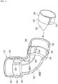
- the pipe joint 10 of the present exemplary embodiment connects together pipes employed in supplying water or the like, and is what is referred to as an elbow pipe joint formed with an L-shaped profile in side view.
- the pipe joint 10 is configured including a joint body 12, a cap 14, seal members 16, a spacer 18, a retention ring 20, a lock ring 22, an adapter 24, and so on.
- the joint body 12 of the present exemplary embodiment is a molded component made of synthetic resin, and is formed with an L-shaped profile in side view.
- the joint body 12 includes a circular tube-shaped first straight section 26 extending in a straight line, a circular tube-shaped second straight section 28 extending in a straight line in a direction orthogonal to the first straight section 26, and a tube-shaped bend section 30 that connects between the first straight section 26 and the second straight section 28.
- first straight section 26 and the second straight section 28 have the same configuration and the same dimensions, explanation only follows regarding the first straight section 26. Note that same reference numerals are allocated to configuration of the second straight section 28 that is the same as that of the first straight section 26, and explanation thereof is omitted.
- a first housing area 32 that has a uniform diameter along its axial direction and a circular shape in cross-section perpendicular to its axial direction is provided inside the first straight section 26 at an opening side of the first straight section 26 (the opposite side to the bend section 30).
- a second housing area 34 that has a uniform diameter along its axial direction and a circular shape that is slightly smaller in diameter than the first housing area 32 in cross-section perpendicular to its axial direction is also provided inside the first straight section 26 at a back side of the first housing area 32 (the bend section 30 side).
- a first step 36 is thereby formed between the first housing area 32 and the second housing area 34 inside the joint body 12.
- a bending flow path 38 is provided bending inside the bend section 30 so as to follow its axial line in cross-section view.
- a corner 38A is provided at a bend inner side, and a curved bend-outer-side curved flow-path face 38B is provided at a bend outer side, of the bending flow path 38.
- the half of an end portion of the bending flow path 38 that is on the curved bend-outer-side curved flow-path face 38B side of the axial line 26CL has a shape (a cross-section profile perpendicular to its axis) that is semicircular with a radius r.
- the half of the end portion that is on the opposite side to the curved bend-outer-side curved flow-path face 38B side of the axial line 26CL has a non-semicircular shape (half of a substantially elliptical shape), such that the end portion has a substantially elliptical shape overall.
- the profile of the corner 38A-side half of the bending flow path 38 in cross-section perpendicular to its axis gradually approaches a semicircular shape on progression from the end portion toward an axial direction central portion of the bending flow path 38.
- the profile of the bending flow path 38 in cross-section perpendicular to its axis gently changes from a substantially elliptical shape to a substantially circular shape on progression from the end portion toward the axial direction central portion.
- An internal diameter (opening area) of the end portion of the bending flow path 38 is smaller than an internal diameter (opening area) of the second housing area 34 of the first straight section 26.
- a second step 40 is formed between the bending flow path 38 and the second housing area 34 inside the joint body 12.
- the adapter 24 illustrated in Figs. 6A, 6B, and 6C is configured as a separate body to the joint body 12 and is inserted into the second housing area 34 of the first straight section 26 and the bending flow path 38.
- the adapter 24 is a molded component made of synthetic resin.
- the adapter 24 includes a circular tube shaped main body 42 for insertion into the second housing area 34 of the first straight section 26.
- An external diameter of the main body 42 is slightly smaller than an internal diameter of the second housing area 34 so as to enable insertion into the second housing area 34.
- An internal diameter of the main body 42 is slightly larger than an internal diameter of a pipe 44 (see Fig. 1 ) so as to enable insertion of the pipe 44.
- a ring shaped wall 46 is integrally formed to one end side of the main body 42.
- the wall 46 is formed with a circular hole 48 that has a smaller diameter than the internal diameter of the main body 42 and the same diameter as the internal diameter of the pipe 44.
- the circular hole 48 is formed coaxially to the main body 42.
- a protrusion 50 is integrally formed to an outer face (a face on the opposite side to the main body 42) of the wall 46. As illustrated in Fig. 6B , the protrusion 50 is curved as viewed along the axial direction. As illustrated in Fig. 6C , an inner peripheral face 50A of the protrusion 50 is curved in a circular arc shape.
- a recess 39 into which the protrusion 50 is fitted is formed in an inner peripheral face of the bend section 30 of the joint body 12.
- the attachment orientation, in other words the positioning, of the protrusion 50 is set by inserting and fitting the protrusion 50 into the recess 39.
- a leading end of the protrusion 50 of one adapter 24 and a leading end of the protrusion 50 of another adapter 24 can be made to contact each other.
- the inner peripheral face 50A of the protrusion 50 is smoothly linked to an inner peripheral face of the circular hole 48 in the wall 46 without any unevenness.
- the profile of the inner peripheral face 50A in cross-section perpendicular to its axis is a circular arc shape with a radius of curvature r that is the same as the inner peripheral face of the circular hole 48, in other words a semicircular shape.
- the circular arc shape of the inner peripheral face 50A with the radius r spans from circular hole 48 to the leading end of the protrusion 50.
- an adapter 24 is also inserted into the second straight section 28.
- the leading end of the protrusion 50 of one adapter 24 inserted into the first straight section 26 and the leading end of the protrusion 50 of the other adapter 24 inserted into the second straight section 28 contact one another.
- a pair of protrusions 52 that extend along the axial direction are formed to an outer peripheral portion of the main body 42 of the adapter 24.
- a pair of grooves 54 that extend along an axial line direction are formed in the second housing area 34 of the joint body 12 where the main body 42 is inserted. The protrusions 52 of the adapter 24 engage (fit together) with the grooves 54.
- configuration is preferably such that friction between the protrusions 52 and the grooves 54 when the protrusions 52 are inserted into the grooves 54 enables the adapter 24 to be retained.
- friction between the protrusions 52 and the grooves 54 may be generated by making the width of the protrusions 52 slightly larger than the width of the grooves 54, or making the height of the protrusions 52 slightly larger than the depth of the grooves 54. This enables the adapter 24 to be suppressed from falling out after the adapter 24 has been inserted into the joint body 12.
- the diameter of the main body 42 slightly larger than the internal diameter of the second housing area 34, enabling the adapter 24 to be press-fit into the second housing area 34 such that friction between the inner peripheral face of the main body 42 and an inner peripheral face of the second housing area 34 retains the adapter 24 inside the joint body 12.
- the seal member 16 formed from an elastic material such as rubber as an example, the spacer 18 formed from synthetic resin as an example, the seal member 16, and the retention ring 20 formed from synthetic resin as an example, are inserted into the first housing area 32 of the first straight section 26 in sequence from the back side (the second housing area 34 side).
- One end side of the retention ring 20 is disposed inside the first housing area 32.
- a large diameter portion 56 with a larger diameter than the one end side is formed at another end side of the retention ring 20.
- the large diameter portion 56 is disposed outside the end portion of the first straight section 26.
- a tapered lock ring retaining portion 58 that gradually increases in diameter on progression toward the other end side is formed around an inner periphery of the other end side of the retention ring 20.
- the cap 14 is formed in a circular tube shape, and is fitted onto an outer periphery of the first straight section 26.
- a step 60 is formed inside the cap 14.
- the large diameter portion 56 of the retention ring 20 and an outer peripheral portion of the lock ring 22 are sandwiched between the step 60 and the end portion of the first straight section 26.
- Plural claws 22A that catch onto an outer peripheral face of the pipe 44 so as to suppress the pipe 44 from detaching are formed to an inner peripheral portion of the lock ring 22.
- the pipe joint 10 of the present exemplary embodiment is what is referred to as a one-touch joint that suppresses the pipe 44 from detaching simply by the pipe 44 being inserted therein.
- the pipe 44 is inserted into the joint body 12 through an opening in the cap 14.
- the pipe 44 is inserted until a leading end thereof abuts the wall 46 of the adapter 24.
- the adapter 24 may be either inserted into the joint body 12 in advance when the pipe joint 10 is assembled at the manufacturing plant, or inserted into the joint body 12 when the pipe 44 is inserted at a construction site.
- friction is generated when the protrusions 52 provided to the adapter 24 are inserted into the grooves 54 provided to the joint body 12, such that the adapter 24 can be suppressed from detaching without having to use adhesive or the like.
- the claws 22A on the inner peripheral side of the lock ring 22 catch onto the outer peripheral face of the pipe 44, such that the pipe 44 is suppressed from detaching.
- the seal members 16 disposed between the pipe 44 and the first housing area 32 make close contact with the outer peripheral face of the pipe 44 and an inner peripheral face of the first housing area 32, such that any gaps between the pipe 44 and the joint body 12 are sealed off by the seal members 16, and water flowing inside the pipe joint is suppressed from leaking out.
- the protrusions 50 of the adapters 24 are disposed adjacent to the corner 38A of the bending flow path 38 so as to cover the corner 38A, such that the inner peripheral faces 50A of the two protrusions 50 are linked together to form a curved face at the bend inner side of the bending flow path 38 as illustrated in Fig. 1 .
- fluid flowing at the bend inner side of the bending flow path 38 changes direction more smoothly than in cases in which the corner 38A is exposed, thereby enabling pressure loss to be reduced.
- the bending flow path 38 of the bend section 30 to which the adapter 24 is attached is bordered by the curved bend-outer-side curved flow-path face 38B at the bend outer side thereof and the inner peripheral face 50A of the protrusion 50 at the bend inner side thereof so as to have a circular cross-section profile with the same diameter as the flow path of the pipe 44.
- the cross-section profile of the flow path does not change mid-flow, thereby enabling pressure loss that would arise due to the cross-section profile of the flow path changing mid-flow to be suppressed.
- the pipe joint 10 of the present exemplary embodiment has the same configuration on either side of the bend section 30, namely on both the first straight section 26 side and the second straight section 28 side.
- the adapter 24 is molded as a separate component to the joint body 12, and may be attached to the joint body 12 post-production.
- the adapter 24 is molded as a separate component to the joint body 12, and may be attached to the joint body 12 post-production.
- the joint body 12 of the present exemplary embodiment forms a bending flow path in which the bend inner side and the bend outer side are both curved faces.
- the bending flow path 38 of the bend section 30 has a substantially elliptical shaped cross-section profile perpendicular to its axial line
- the adapters 24 are inserted into the first straight section 26 and the second straight section 28, such that the protrusions 50 of the adapters 24 are disposed at the portion where the cross-section profile of the bending flow path 38 has a non-semicircular shape.
- the flow path with a circular cross-section profile inside one of the pipes 44 and the flow path with a circular cross-section profile inside the other of the pipes 44 are connected through the circular cross-sectioned flow path inside the bend section 30 that has the same circular cross-section profile and is formed with the same internal diameter as the pipes 44.
- This enables water to flow smoothly from the first straight section 26 side toward the second straight section 28, and from the second straight section 28 side toward the first straight section 26, and also enables an increase in pressure loss occurring in cases in which the flow path bends and the cross-section profile of the flow path changes at the bend section (changes from a circular cross-section to an elliptical cross-section) to be suppressed.
- the pipe joint 70 of the present exemplary embodiment is a T-shaped one-touch joint referred to as Tee pipe joint.
- the pipe joint 70 is formed with line symmetry on either side of the second straight section 28, and includes a T-shaped joint body 72.
- a third straight section 74 with the same structure as the first straight section 26 is formed so as to face in the opposite direction to the first straight section 26 on the opposite side of the joint body 72 to the first straight section 26.
- a corner 76 is thereby formed by the orthogonal second straight section 28 and third straight section 74 inside the joint body 72.
- an extension direction of the first straight section 26 is an arrow R direction (a first direction)
- an extension direction of the third straight section 74 is an arrow L direction (a second direction) that is the opposite direction to the arrow R direction.
- An extension direction of the second straight section 28 is an arrow U direction (a third direction) that is orthogonal to both the arrow R extension direction of the first straight section 26 and the arrow L extension direction of the third straight section 74.
- a pair of protrusions 50 that both face in opposite directions to a radial direction are provided to an adapter 78 of the present exemplary embodiment that is inserted into the second straight section 28.
- the protrusion 50 of the adapter 24 inserted into the third straight section 74 and one of the protrusions 50 of the adapter 78 inserted into the second straight section 28 are disposed adjacent to the corner 76 so as to cover the corner 76, and a curving curved flow-path inner wall face is formed by the inner peripheral faces 50A of the respective protrusions 50.
- the present disclosure was applied to an L-shaped pipe joint 10 referred to as an elbow pipe j oint
- an example was described in which the present disclosure was applied to an T-shaped pipe joint 70 referred to as a Tee pipe joint.
- the present disclosure may be applied to joints other than elbow or Tee joints, such as a cross-shaped pipe joint, and may be applied to flow path structures other than pipe joints, such as a pipe that simply bends.
- the pipe joint of the second exemplary embodiment may be provided with a fourth straight section with the same configuration as the second straight section 28 on the opposite side to the second straight section 28.
- an angle formed by the first straight section 26 and the second straight section 28 is 90° in the pipe joint 10 of the first exemplary embodiment, an angle other than 90° may be formed.
- the joint body 12 may be molded using a transparent synthetic resin such that presence or absence of the adapter 24 is easily determined from the exterior.
- the pipe joint 10 of the above exemplary embodiment is what is referred to as a one-touch joint in which the pipe 44 is held in place simply by being inserted
- the configuration of the connecting section to the pipe 44 is not limited to the configuration of the above exemplary embodiment.
- Another, conventionally known configuration (such as screw fastening) may be applied.
- the adapter 24 of the above exemplary embodiments includes the circular tube shaped main body 42, as long as at the least protrusion 50 is provided, the main body 42 does not necessarily have to be provided.
- the main body 42 may be configured by half of a circular tube shape.
- protrusions 52 for retaining the adapter 24 in the joint body 12 are provided to the main body 42 in the pipe joint 10 of the above exemplary embodiment, the protrusions 52 and the grooves 54 in the joint body 12 may be omitted if not required.
- the adapter 24 described above is a molded component made of synthetic resin, and as an example, may be molded using a mold 62 such as that illustrated in Fig. 8 .
- the mold 62 is provided with a recess 62A for forming an outer side of the adapter 24.
- the mold 62 is also provided with a first slider pin 64 for forming an inner side of the main body 42 of the adapter 24, and a second slider pin 66 for forming an inner side of the protrusion 50 and the circular hole 48, these slider pins being capable of moving in and out of the mold 62.
- the mold 62 is capable of being divided into two parts in either an up-down direction in Fig. 8 , or a depth direction of the page in Fig. 8 .
- Molten synthetic resin is injected into the recess 62A in the mold 62 and into a cavity formed by the first slider pin 64 and the second slider pin 66. After the synthetic resin has cooled, the first slider pin 64 and the second slider pin 66 are removed and the mold 62 is opened up to obtain the adapter 24.
Landscapes
- Engineering & Computer Science (AREA)
- General Engineering & Computer Science (AREA)
- Mechanical Engineering (AREA)
- Quick-Acting Or Multi-Walled Pipe Joints (AREA)
- Branch Pipes, Bends, And The Like (AREA)
- Moulds For Moulding Plastics Or The Like (AREA)
Claims (3)
- Structure de voies d'écoulement qui connecte une pluralité de voies d'écoulement les unes aux autres, s'étendant chacune dans une direction différente, la structure de voies d'écoulement comprenant :un corps de liaison (12) comprenant un coin interne de la voie d'écoulement (38A) formé au niveau d'une section de connexion entre l'une des voies d'écoulement et une autre des voies d'écoulement ; etun adaptateur (24) disposé de manière adjacente au coin interne de la voie d'écoulement (38A) de sorte à coupler l'une à l'autre ladite une des voies d'écoulement et ladite autre des voies d'écoulement au niveau d'une face de paroi interne courbée incurvée de voie d'écoulement,dans laquelle :l'adaptateur (24) inclut une saillie (50) qui fait saillie vers un côté interne de la voie d'écoulement, de sorte à former la face de paroi interne courbée de la voie d'écoulement ;une partie de retenue (52) est fournie au niveau de l'adaptateur ;une partie pour la retenue (54) qui s'engage dans la partie de retenue (52) de sorte à retenir l'adaptateur (24) à l'intérieur de la voie d'écoulement est fournie au niveau d'une face interne de la voie d'écoulement ;l'adaptateur (24) inclut une section tubulaire (42) destinée à être insérée dans la voie d'écoulement ;la saillie (50) est fournie au niveau d'un côté d'extrémité, dans la direction axiale, de la section tubulaire (42) ;la partie de retenue (52) est fournie au niveau d'une partie périphérique externe de la section tubulaire (42) ; caractérisée en ce que :la partie de retenue (52) comprend une paire de saillies (52) qui s'étendent dans la direction axiale et sont formées sur une partie périphérique externe de la section tubulaire (42) qui forme un corps principal (42) de l'adaptateur (24) ;une partie pour la retenue (54) comprend une paire de rainures (54) qui s'étendent dans une direction de ligne axiale et sont formées dans une zone de logement (34) du corps de liaison (12) où le corps principal (42) est inséré, etles saillies (52) de l'adaptateur (24) s'engagent dans les rainures (54).
- Structure de voies d'écoulement selon la revendication 1, dans laquelle le coin interne de la voie d'écoulement (38A) est configuré en connectant ladite une des voies d'écoulement et ladite autre des voies d'écoulement l'une à l'autre à angle droit.
- Structure de voies d'écoulement selon les revendications 1 ou 2, dans laquelle :
la pluralité de voies d'écoulement inclut :une première voie d'écoulement s'étendant dans une première direction ;une deuxième voie d'écoulement s'étendant dans une deuxième direction qui est une direction opposée à la première direction ; etune troisième voie d'écoulement s'étendant dans une troisième direction qui est orthogonale à la première direction et à la deuxième direction.
Applications Claiming Priority (2)
| Application Number | Priority Date | Filing Date | Title |
|---|---|---|---|
| JP2019153420A JP7425563B2 (ja) | 2019-08-26 | 2019-08-26 | 流路構造 |
| PCT/JP2020/032068 WO2021039804A1 (fr) | 2019-08-26 | 2020-08-25 | Structure de passage d'écoulement |
Publications (3)
| Publication Number | Publication Date |
|---|---|
| EP4023921A1 EP4023921A1 (fr) | 2022-07-06 |
| EP4023921A4 EP4023921A4 (fr) | 2023-08-30 |
| EP4023921B1 true EP4023921B1 (fr) | 2025-01-22 |
Family
ID=74677254
Family Applications (1)
| Application Number | Title | Priority Date | Filing Date |
|---|---|---|---|
| EP20857469.9A Active EP4023921B1 (fr) | 2019-08-26 | 2020-08-25 | Structure de passage d'écoulement |
Country Status (5)
| Country | Link |
|---|---|
| EP (1) | EP4023921B1 (fr) |
| JP (1) | JP7425563B2 (fr) |
| CN (1) | CN114286911A (fr) |
| TW (1) | TWI860395B (fr) |
| WO (1) | WO2021039804A1 (fr) |
Family Cites Families (18)
| Publication number | Priority date | Publication date | Assignee | Title |
|---|---|---|---|---|
| JPS627522A (ja) * | 1985-07-04 | 1987-01-14 | Hitachi Metals Ltd | 防食管継手の製造法 |
| KR200309127Y1 (ko) | 1999-01-19 | 2003-03-29 | 주식회사 프럼파스트 | 파이프의 연결구 조립체 |
| JP2001116182A (ja) | 1999-10-20 | 2001-04-27 | Tsutomu Takahashi | 電熱融解接合部を有する樹脂パイプ継手 |
| CN1164884C (zh) | 2001-10-26 | 2004-09-01 | 甘国工 | 有钢骨架增强体的电热熔硅烷交联聚乙烯管道连接件 |
| US7160497B2 (en) | 2002-11-12 | 2007-01-09 | Entegris, Inc. | Process and apparatus for molding polymer fittings |
| JP5616568B2 (ja) | 2007-12-18 | 2014-10-29 | 積水化学工業株式会社 | 脚部継手及びこの脚部継手を用いた排水システム |
| JP5596489B2 (ja) * | 2010-10-12 | 2014-09-24 | 積水化学工業株式会社 | 継手用アダプター及び該継手用アダプターを用いた旋回羽根付き排水管継手 |
| CN103411077B (zh) | 2013-07-19 | 2016-06-29 | 河南联塑实业有限公司 | 一种塑料弯头 |
| CN203431369U (zh) | 2013-08-31 | 2014-02-12 | 赵逸 | 一种易拆装管道接头 |
| CN105135131B (zh) * | 2015-08-13 | 2017-05-31 | 中化二建集团有限公司 | 高压乙炔输送管道及其制作方法 |
| JP6832085B2 (ja) * | 2016-07-15 | 2021-02-24 | 株式会社ブリヂストン | 中空の成形品、及び、中空の成形品の製造方法 |
| JP6966841B2 (ja) | 2017-01-31 | 2021-11-17 | ミライアル株式会社 | 樹脂製管継手 |
| DE202017102366U1 (de) | 2017-04-21 | 2018-07-25 | Voss Fluid Gmbh | Fluidarmatur für eine Fluidleitung |
| JP7019988B2 (ja) | 2017-07-27 | 2022-02-16 | 株式会社オンダ製作所 | 樹脂製エルボ継手 |
| JP2019153420A (ja) | 2018-03-01 | 2019-09-12 | 矢崎総業株式会社 | 電線の導体の接合方法および電線 |
| JP7372039B2 (ja) | 2018-03-14 | 2023-10-31 | 積水化学工業株式会社 | アダプタおよび継手構造 |
| JP7307875B2 (ja) | 2018-10-02 | 2023-07-13 | 株式会社オンダ製作所 | 樹脂製チーズ継手 |
| JP3220335U (ja) | 2018-12-17 | 2019-02-28 | 株式会社オンダ製作所 | 樹脂製エルボ継手 |
-
2019
- 2019-08-26 JP JP2019153420A patent/JP7425563B2/ja active Active
-
2020
- 2020-08-25 EP EP20857469.9A patent/EP4023921B1/fr active Active
- 2020-08-25 WO PCT/JP2020/032068 patent/WO2021039804A1/fr not_active Ceased
- 2020-08-25 CN CN202080059697.3A patent/CN114286911A/zh active Pending
- 2020-08-26 TW TW109129137A patent/TWI860395B/zh active
Also Published As
| Publication number | Publication date |
|---|---|
| JP2021032342A (ja) | 2021-03-01 |
| CN114286911A (zh) | 2022-04-05 |
| TWI860395B (zh) | 2024-11-01 |
| EP4023921A4 (fr) | 2023-08-30 |
| WO2021039804A1 (fr) | 2021-03-04 |
| JP7425563B2 (ja) | 2024-01-31 |
| EP4023921A1 (fr) | 2022-07-06 |
| TW202126945A (zh) | 2021-07-16 |
Similar Documents
| Publication | Publication Date | Title |
|---|---|---|
| US7393019B2 (en) | Tube connection assembly | |
| JP7605252B2 (ja) | 樹脂製チーズ継手 | |
| CN114370086A (zh) | 软管的应用、流体组件和卫生配件 | |
| JP2023126826A (ja) | 樹脂製エルボ継手 | |
| EP4023921A1 (fr) | Structure de passage d'écoulement | |
| CN216867870U (zh) | 一种防泄漏大流量活接管件 | |
| JP3220335U (ja) | 樹脂製エルボ継手 | |
| US20250230889A1 (en) | Pipe branch structure | |
| CN217634447U (zh) | 单向限流接头 | |
| CN106195479A (zh) | 管路部件连接用连接构件及其制造方法 | |
| JP6832085B2 (ja) | 中空の成形品、及び、中空の成形品の製造方法 | |
| JP2019011857A (ja) | 樹脂製エルボ継手 | |
| TWM613445U (zh) | 快插管接頭 | |
| JP7107919B2 (ja) | バルブハウジング、バルブ及びバルブハウジングの製造方法 | |
| JP2024144693A (ja) | 樹脂製継手 | |
| US11708928B2 (en) | Resin joint, channel block, and fluid control device | |
| CN114754212B (zh) | 一种转接头、其制备方法及双把龙头 | |
| CN221347991U (zh) | 阀芯及柱塞式换向阀 | |
| CN221504016U (zh) | 一种角阀 | |
| CN210290840U (zh) | 一种阀体组件 | |
| CN111742171B (zh) | 用于回路元件的连接器 | |
| CN222392265U (zh) | 一种快插阴接头及快插结构 | |
| JP4220211B2 (ja) | 配管用コネクタ | |
| CN224245703U (zh) | 浮动连接管组 | |
| JP6635678B2 (ja) | コネクタ部材による管路ブロックの管路接続構造 |
Legal Events
| Date | Code | Title | Description |
|---|---|---|---|
| STAA | Information on the status of an ep patent application or granted ep patent |
Free format text: STATUS: THE INTERNATIONAL PUBLICATION HAS BEEN MADE |
|
| PUAI | Public reference made under article 153(3) epc to a published international application that has entered the european phase |
Free format text: ORIGINAL CODE: 0009012 |
|
| STAA | Information on the status of an ep patent application or granted ep patent |
Free format text: STATUS: REQUEST FOR EXAMINATION WAS MADE |
|
| 17P | Request for examination filed |
Effective date: 20220302 |
|
| AK | Designated contracting states |
Kind code of ref document: A1 Designated state(s): AL AT BE BG CH CY CZ DE DK EE ES FI FR GB GR HR HU IE IS IT LI LT LU LV MC MK MT NL NO PL PT RO RS SE SI SK SM TR |
|
| DAV | Request for validation of the european patent (deleted) | ||
| DAX | Request for extension of the european patent (deleted) | ||
| A4 | Supplementary search report drawn up and despatched |
Effective date: 20230802 |
|
| RIC1 | Information provided on ipc code assigned before grant |
Ipc: F16L 37/091 20060101ALI20230727BHEP Ipc: F16L 43/00 20060101AFI20230727BHEP |
|
| GRAP | Despatch of communication of intention to grant a patent |
Free format text: ORIGINAL CODE: EPIDOSNIGR1 |
|
| STAA | Information on the status of an ep patent application or granted ep patent |
Free format text: STATUS: GRANT OF PATENT IS INTENDED |
|
| RIC1 | Information provided on ipc code assigned before grant |
Ipc: F16L 37/091 20060101ALI20240812BHEP Ipc: F16L 43/00 20060101AFI20240812BHEP |
|
| INTG | Intention to grant announced |
Effective date: 20240823 |
|
| P01 | Opt-out of the competence of the unified patent court (upc) registered |
Free format text: CASE NUMBER: APP_49452/2024 Effective date: 20240830 |
|
| GRAS | Grant fee paid |
Free format text: ORIGINAL CODE: EPIDOSNIGR3 |
|
| GRAA | (expected) grant |
Free format text: ORIGINAL CODE: 0009210 |
|
| STAA | Information on the status of an ep patent application or granted ep patent |
Free format text: STATUS: THE PATENT HAS BEEN GRANTED |
|
| AK | Designated contracting states |
Kind code of ref document: B1 Designated state(s): AL AT BE BG CH CY CZ DE DK EE ES FI FR GB GR HR HU IE IS IT LI LT LU LV MC MK MT NL NO PL PT RO RS SE SI SK SM TR |
|
| REG | Reference to a national code |
Ref country code: GB Ref legal event code: FG4D |
|
| REG | Reference to a national code |
Ref country code: CH Ref legal event code: EP |
|
| REG | Reference to a national code |
Ref country code: IE Ref legal event code: FG4D |
|
| REG | Reference to a national code |
Ref country code: DE Ref legal event code: R096 Ref document number: 602020045297 Country of ref document: DE |
|
| REG | Reference to a national code |
Ref country code: NL Ref legal event code: MP Effective date: 20250122 |
|
| PG25 | Lapsed in a contracting state [announced via postgrant information from national office to epo] |
Ref country code: NL Free format text: LAPSE BECAUSE OF FAILURE TO SUBMIT A TRANSLATION OF THE DESCRIPTION OR TO PAY THE FEE WITHIN THE PRESCRIBED TIME-LIMIT Effective date: 20250122 |
|
| PG25 | Lapsed in a contracting state [announced via postgrant information from national office to epo] |
Ref country code: RS Free format text: LAPSE BECAUSE OF FAILURE TO SUBMIT A TRANSLATION OF THE DESCRIPTION OR TO PAY THE FEE WITHIN THE PRESCRIBED TIME-LIMIT Effective date: 20250422 |
|
| PG25 | Lapsed in a contracting state [announced via postgrant information from national office to epo] |
Ref country code: FI Free format text: LAPSE BECAUSE OF FAILURE TO SUBMIT A TRANSLATION OF THE DESCRIPTION OR TO PAY THE FEE WITHIN THE PRESCRIBED TIME-LIMIT Effective date: 20250122 |
|
| PG25 | Lapsed in a contracting state [announced via postgrant information from national office to epo] |
Ref country code: PL Free format text: LAPSE BECAUSE OF FAILURE TO SUBMIT A TRANSLATION OF THE DESCRIPTION OR TO PAY THE FEE WITHIN THE PRESCRIBED TIME-LIMIT Effective date: 20250122 |
|
| PG25 | Lapsed in a contracting state [announced via postgrant information from national office to epo] |
Ref country code: ES Free format text: LAPSE BECAUSE OF FAILURE TO SUBMIT A TRANSLATION OF THE DESCRIPTION OR TO PAY THE FEE WITHIN THE PRESCRIBED TIME-LIMIT Effective date: 20250122 |
|
| REG | Reference to a national code |
Ref country code: LT Ref legal event code: MG9D |
|
| PG25 | Lapsed in a contracting state [announced via postgrant information from national office to epo] |
Ref country code: IS Free format text: LAPSE BECAUSE OF FAILURE TO SUBMIT A TRANSLATION OF THE DESCRIPTION OR TO PAY THE FEE WITHIN THE PRESCRIBED TIME-LIMIT Effective date: 20250522 Ref country code: NO Free format text: LAPSE BECAUSE OF FAILURE TO SUBMIT A TRANSLATION OF THE DESCRIPTION OR TO PAY THE FEE WITHIN THE PRESCRIBED TIME-LIMIT Effective date: 20250422 |
|
| REG | Reference to a national code |
Ref country code: AT Ref legal event code: MK05 Ref document number: 1761697 Country of ref document: AT Kind code of ref document: T Effective date: 20250122 |
|
| PG25 | Lapsed in a contracting state [announced via postgrant information from national office to epo] |
Ref country code: HR Free format text: LAPSE BECAUSE OF FAILURE TO SUBMIT A TRANSLATION OF THE DESCRIPTION OR TO PAY THE FEE WITHIN THE PRESCRIBED TIME-LIMIT Effective date: 20250122 |
|
| PG25 | Lapsed in a contracting state [announced via postgrant information from national office to epo] |
Ref country code: LV Free format text: LAPSE BECAUSE OF FAILURE TO SUBMIT A TRANSLATION OF THE DESCRIPTION OR TO PAY THE FEE WITHIN THE PRESCRIBED TIME-LIMIT Effective date: 20250122 Ref country code: PT Free format text: LAPSE BECAUSE OF FAILURE TO SUBMIT A TRANSLATION OF THE DESCRIPTION OR TO PAY THE FEE WITHIN THE PRESCRIBED TIME-LIMIT Effective date: 20250522 |
|
| PG25 | Lapsed in a contracting state [announced via postgrant information from national office to epo] |
Ref country code: BG Free format text: LAPSE BECAUSE OF FAILURE TO SUBMIT A TRANSLATION OF THE DESCRIPTION OR TO PAY THE FEE WITHIN THE PRESCRIBED TIME-LIMIT Effective date: 20250122 Ref country code: GR Free format text: LAPSE BECAUSE OF FAILURE TO SUBMIT A TRANSLATION OF THE DESCRIPTION OR TO PAY THE FEE WITHIN THE PRESCRIBED TIME-LIMIT Effective date: 20250423 |
|
| PG25 | Lapsed in a contracting state [announced via postgrant information from national office to epo] |
Ref country code: AT Free format text: LAPSE BECAUSE OF FAILURE TO SUBMIT A TRANSLATION OF THE DESCRIPTION OR TO PAY THE FEE WITHIN THE PRESCRIBED TIME-LIMIT Effective date: 20250122 |
|
| PG25 | Lapsed in a contracting state [announced via postgrant information from national office to epo] |
Ref country code: SE Free format text: LAPSE BECAUSE OF FAILURE TO SUBMIT A TRANSLATION OF THE DESCRIPTION OR TO PAY THE FEE WITHIN THE PRESCRIBED TIME-LIMIT Effective date: 20250122 |
|
| PG25 | Lapsed in a contracting state [announced via postgrant information from national office to epo] |
Ref country code: SM Free format text: LAPSE BECAUSE OF FAILURE TO SUBMIT A TRANSLATION OF THE DESCRIPTION OR TO PAY THE FEE WITHIN THE PRESCRIBED TIME-LIMIT Effective date: 20250122 |
|
| PG25 | Lapsed in a contracting state [announced via postgrant information from national office to epo] |
Ref country code: DK Free format text: LAPSE BECAUSE OF FAILURE TO SUBMIT A TRANSLATION OF THE DESCRIPTION OR TO PAY THE FEE WITHIN THE PRESCRIBED TIME-LIMIT Effective date: 20250122 |
|
| PGFP | Annual fee paid to national office [announced via postgrant information from national office to epo] |
Ref country code: DE Payment date: 20250820 Year of fee payment: 6 |
|
| PG25 | Lapsed in a contracting state [announced via postgrant information from national office to epo] |
Ref country code: IT Free format text: LAPSE BECAUSE OF FAILURE TO SUBMIT A TRANSLATION OF THE DESCRIPTION OR TO PAY THE FEE WITHIN THE PRESCRIBED TIME-LIMIT Effective date: 20250122 |
|
| PGFP | Annual fee paid to national office [announced via postgrant information from national office to epo] |
Ref country code: GB Payment date: 20250820 Year of fee payment: 6 |
|
| PG25 | Lapsed in a contracting state [announced via postgrant information from national office to epo] |
Ref country code: CZ Free format text: LAPSE BECAUSE OF FAILURE TO SUBMIT A TRANSLATION OF THE DESCRIPTION OR TO PAY THE FEE WITHIN THE PRESCRIBED TIME-LIMIT Effective date: 20250122 Ref country code: EE Free format text: LAPSE BECAUSE OF FAILURE TO SUBMIT A TRANSLATION OF THE DESCRIPTION OR TO PAY THE FEE WITHIN THE PRESCRIBED TIME-LIMIT Effective date: 20250122 |
|
| REG | Reference to a national code |
Ref country code: DE Ref legal event code: R097 Ref document number: 602020045297 Country of ref document: DE |
|
| PG25 | Lapsed in a contracting state [announced via postgrant information from national office to epo] |
Ref country code: RO Free format text: LAPSE BECAUSE OF FAILURE TO SUBMIT A TRANSLATION OF THE DESCRIPTION OR TO PAY THE FEE WITHIN THE PRESCRIBED TIME-LIMIT Effective date: 20250122 |
|
| PG25 | Lapsed in a contracting state [announced via postgrant information from national office to epo] |
Ref country code: SK Free format text: LAPSE BECAUSE OF FAILURE TO SUBMIT A TRANSLATION OF THE DESCRIPTION OR TO PAY THE FEE WITHIN THE PRESCRIBED TIME-LIMIT Effective date: 20250122 |
|
| PLBE | No opposition filed within time limit |
Free format text: ORIGINAL CODE: 0009261 |
|
| STAA | Information on the status of an ep patent application or granted ep patent |
Free format text: STATUS: NO OPPOSITION FILED WITHIN TIME LIMIT |
|
| REG | Reference to a national code |
Ref country code: CH Ref legal event code: L10 Free format text: ST27 STATUS EVENT CODE: U-0-0-L10-L00 (AS PROVIDED BY THE NATIONAL OFFICE) Effective date: 20251203 |
|
| 26N | No opposition filed |
Effective date: 20251023 |
|
| REG | Reference to a national code |
Ref country code: CH Ref legal event code: H13 Free format text: ST27 STATUS EVENT CODE: U-0-0-H10-H13 (AS PROVIDED BY THE NATIONAL OFFICE) Effective date: 20260324 |
|
| PG25 | Lapsed in a contracting state [announced via postgrant information from national office to epo] |
Ref country code: MC Free format text: LAPSE BECAUSE OF FAILURE TO SUBMIT A TRANSLATION OF THE DESCRIPTION OR TO PAY THE FEE WITHIN THE PRESCRIBED TIME-LIMIT Effective date: 20250122 |
|
| PG25 | Lapsed in a contracting state [announced via postgrant information from national office to epo] |
Ref country code: LU Free format text: LAPSE BECAUSE OF NON-PAYMENT OF DUE FEES Effective date: 20250825 |
|
| PG25 | Lapsed in a contracting state [announced via postgrant information from national office to epo] |
Ref country code: CH Free format text: LAPSE BECAUSE OF NON-PAYMENT OF DUE FEES Effective date: 20250831 |