EP4024058B1 - Module de test par voie hertzienne et système de test - Google Patents
Module de test par voie hertzienne et système de test Download PDFInfo
- Publication number
- EP4024058B1 EP4024058B1 EP21150211.7A EP21150211A EP4024058B1 EP 4024058 B1 EP4024058 B1 EP 4024058B1 EP 21150211 A EP21150211 A EP 21150211A EP 4024058 B1 EP4024058 B1 EP 4024058B1
- Authority
- EP
- European Patent Office
- Prior art keywords
- test
- module
- interface
- radio frequency
- path
- Prior art date
- Legal status (The legal status is an assumption and is not a legal conclusion. Google has not performed a legal analysis and makes no representation as to the accuracy of the status listed.)
- Active
Links
Images
Classifications
-
- H—ELECTRICITY
- H04—ELECTRIC COMMUNICATION TECHNIQUE
- H04B—TRANSMISSION
- H04B17/00—Monitoring; Testing
- H04B17/10—Monitoring; Testing of transmitters
- H04B17/11—Monitoring; Testing of transmitters for calibration
-
- G—PHYSICS
- G01—MEASURING; TESTING
- G01R—MEASURING ELECTRIC VARIABLES; MEASURING MAGNETIC VARIABLES
- G01R29/00—Arrangements for measuring or indicating electric quantities not covered by groups G01R19/00 - G01R27/00
- G01R29/08—Measuring electromagnetic field characteristics
- G01R29/10—Radiation diagrams of antennas
-
- H—ELECTRICITY
- H04—ELECTRIC COMMUNICATION TECHNIQUE
- H04B—TRANSMISSION
- H04B17/00—Monitoring; Testing
- H04B17/10—Monitoring; Testing of transmitters
- H04B17/11—Monitoring; Testing of transmitters for calibration
- H04B17/14—Monitoring; Testing of transmitters for calibration of the whole transmission and reception path, e.g. self-test loop-back
-
- G—PHYSICS
- G01—MEASURING; TESTING
- G01R—MEASURING ELECTRIC VARIABLES; MEASURING MAGNETIC VARIABLES
- G01R29/00—Arrangements for measuring or indicating electric quantities not covered by groups G01R19/00 - G01R27/00
- G01R29/08—Measuring electromagnetic field characteristics
- G01R29/0864—Measuring electromagnetic field characteristics characterised by constructional or functional features
- G01R29/0878—Sensors; antennas; probes; detectors
-
- G—PHYSICS
- G01—MEASURING; TESTING
- G01R—MEASURING ELECTRIC VARIABLES; MEASURING MAGNETIC VARIABLES
- G01R31/00—Arrangements for testing electric properties; Arrangements for locating electric faults; Arrangements for electrical testing characterised by what is being tested not provided for elsewhere
-
- G—PHYSICS
- G01—MEASURING; TESTING
- G01R—MEASURING ELECTRIC VARIABLES; MEASURING MAGNETIC VARIABLES
- G01R35/00—Testing or calibrating of apparatus covered by the other groups of this subclass
- G01R35/005—Calibrating; Standards or reference devices, e.g. voltage or resistance standards, "golden" references
-
- H—ELECTRICITY
- H04—ELECTRIC COMMUNICATION TECHNIQUE
- H04B—TRANSMISSION
- H04B1/00—Details of transmission systems, not covered by a single one of groups H04B3/00 - H04B13/00; Details of transmission systems not characterised by the medium used for transmission
- H04B1/02—Transmitters
- H04B1/04—Circuits
- H04B1/0466—Fault detection or indication
-
- H—ELECTRICITY
- H04—ELECTRIC COMMUNICATION TECHNIQUE
- H04B—TRANSMISSION
- H04B17/00—Monitoring; Testing
- H04B17/0082—Monitoring; Testing using service channels; using auxiliary channels
- H04B17/0085—Monitoring; Testing using service channels; using auxiliary channels using test signal generators
-
- H—ELECTRICITY
- H04—ELECTRIC COMMUNICATION TECHNIQUE
- H04B—TRANSMISSION
- H04B17/00—Monitoring; Testing
- H04B17/10—Monitoring; Testing of transmitters
- H04B17/15—Performance testing
- H04B17/191—Over-the-air testing
-
- H—ELECTRICITY
- H04—ELECTRIC COMMUNICATION TECHNIQUE
- H04B—TRANSMISSION
- H04B17/00—Monitoring; Testing
- H04B17/20—Monitoring; Testing of receivers
- H04B17/23—Indication means, e.g. displays, alarms, audible means
-
- H—ELECTRICITY
- H04—ELECTRIC COMMUNICATION TECHNIQUE
- H04B—TRANSMISSION
- H04B7/00—Radio transmission systems, i.e. using radiation field
- H04B7/02—Diversity systems; Multi-antenna system, i.e. transmission or reception using multiple antennas
- H04B7/028—Spatial transmit diversity using a single antenna at the transmitter
Definitions
- the invention relates to an over-the-air test module for testing a device under test over-the-air. Further, the invention relates to a test system for testing a device under test over-the-air.
- test systems are known that are used for testing a device under test (DUT) over-the-air (OTA).
- the test systems typically comprise a signal generator and/or a signal analyzer, which depends on the respective testing purpose of the device under test.
- the signal generator or the signal analyzer relate to a test device that is used to test the device under test with regard to its transmission or rather reception characteristics.
- the respective device has at least one port with which an antenna is connected for testing the device under test over-the-air (OTA), namely in a wireless manner.
- OTA over-the-air
- a reference plane of the respective test setup namely the OTA setup
- the test device is connected with the antenna via a cable, thereby establishing the OTA setup that has not been calibrated accordingly. Therefore, the reference plane shall be extended to the antenna for ensuring proper testing of the device under test. For extending the reference plane to the antenna, it is thus necessary to manually calibrate the OTA setup appropriately, namely after connecting the antenna with the test device.
- the manual calibration is complex and time-consuming. Further, the manual calibration is prone to failure such that the calibration is done in an improper manner, yielding inappropriate measurement results when testing the device under test by means of the test system.
- an over-the-air test module for testing a device under test over-the-air which comprises an antenna connected to a mixer which is connected via a first connector to a local oscillator.
- US 10,056,987 B1 shows a system for measuring radio frequency power of an incoming radio frequency signal.
- the main idea is to provide a pre-calibrated over-the-air (OTA) test module that can be connected with at least one test device easily, for instance a signal generator, a signal analyzer and/or a power meter.
- OTA over-the-air
- the reference plane of the over-the-air setup can be extended automatically to the antenna from the respective port of the test device connected with the test module since the test module is pre-calibrated. Accordingly, the reference plane is automatically extended, e.g. without any manual calibration, to the point of the OTA setup that is as close as possible to the device under test, namely the antenna.
- the additional and integrated detector module provides an additional monitoring purpose of the signal processed by the test module, namely the radio frequency signal.
- the detector module is adapted for deriving a measurement signal from the signal processed by the test module, namely a radio frequency or rather high frequency signal.
- the detector module may be established by a diode sensor, which is configured to perform a rectification of a signal derived from the radio frequency signal.
- the signal derived from the signal processed by the test module namely the measurement signal
- the signal derived from the signal processed by the test module can be outputted via the interface for further analyzing purposes.
- the respective measurement signal provided by the detector module may be forwarded to the power meter, the signal analyzer or the feedback interface, which is connected with the second path via the interface.
- the test module can be used for testing receiving properties of the device under test as well as transmitting properties of the device under test since the same path, namely the first path, can be used for forwarding the respective signal to the antenna or rather from the antenna.
- the processing direction depends on the operation mode or rather the testing purpose.
- test module is integrated module having a housing that encompasses the radio frequency module, the first path, the second path and the detector module.
- the housing also encompasses the antenna.
- the antenna is an integrated antenna.
- the connector and/or the interface may be established at an outer surface of the housing of the test module.
- the respective connections or rather lines established between the internal components of the test module are fixed ones such that stable and consistent characteristics of the test module can be ensured when performing tests.
- the connector is a radio frequency connector and/or the interface is a radio frequency interface.
- the test module is used for processing radio frequency signals that are to be transmitted by the antenna and/or received by the antenna. Hence, the radio frequency signals are forwarded to the antenna from the test device or rather forwarded from the antenna to the respective test device connected with the test module.
- the radio frequency connector and/or the radio frequency interface are/is established by a coaxial port.
- the coaxial port ensures that the test module can be connected easily with the respective test device via a coaxial cable.
- the respective port of the test device is also established by a coaxial port.
- the connector and/or the interface are/is reconnectable. This means that the connection established via the connector and/or the interface can be solved and re-connected easily.
- the connector and/or the interface relate to socket(s) configured to receive a plug, particularly a plug-like end of a cable.
- test module may be used in different operational settings or rather operation modes, namely different OTA setups, in which different characteristics of the device under test can be tested.
- the connector of the test module may be connected with a first test device in a first setup, whereas the connector of the test module is connected with another test device in a second setup. This can be ensured due to the fact that the connector is reconnectable. The same applies for the interface that can be connected with different test devices as well.
- the radio frequency module is a coupler, particularly directional coupler.
- the radio frequency module is established by a splitter, a divider or a combiner.
- the radio frequency module can be used to split or rather divide a radio frequency signal received via the antenna that has been forwarded from the antenna to the radio frequency module.
- the radio frequency module may also be established by a combiner in order to combine signals received via both paths, particularly received via the connector and the interface. Then, the combined signal is forwarded from the radio frequency module to the antenna for being transmitted towards the device under test.
- the invention also provides a test system for testing a device under test over-the-air.
- the test system comprises the over-the-air test module mentioned above as well as a power meter, a signal analyzer and/or a signal generator. Accordingly, the test system comprises separately formed devices that may be connected with the test module.
- the power meter may also be integrated within the signal generator and/or signal analyzer.
- the signal analyzer and/or the signal generator may have a display and a processing circuit.
- the processing circuit is configured to calculate a field strength based on information received from the test module, particularly the detection module.
- the display is configured to indicate the field strength calculated. Accordingly, an operator of the test system can be informed with regard to the field strength such that information is obtained for characterizing the device under test.
- the phrase "at least one of A, B, and C", for example, means (A), (B), (C), (A and B), (A and C), (B and C), or (A, B, and C), including all further possible permutations when more than three elements are listed.
- the term “at least one of A and B” generally means “A and/or B", namely "A” alone, “B” alone or "A and B”.
- unit and/or “module” are/is understood to describe suitable hardware, suitable software, or a combination of hardware and software that is configured to have a certain functionality.
- the hardware may, inter alia, comprise a CPU, a GPU, an FPGA, an ASIC, or other types of electronic circuitry.
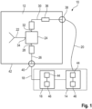
- the second path 30 also comprises an interface 38 that is configured to be connected with a first of the two test devices 14, 16 with the over-the-air test module 12, namely the first test device 14.
- the first test device 14 may be a power meter, a signal analyzer or a feedback interface, for instance a feedback interface of a signal generator.
- the first path 26 comprises a connector 40 that is configured to connect a second of the two test devices 14, 16 with the over-the-air test module 12, namely the second test device 16.
- the second test device 16 may be established by a signal analyzer or a signal generator.
- the power meter may be integrated within the signal analyzer or the signal generator such that a single separately formed device is connected with the test module 12 via the connector 40 and the interface 38 as indicated by the dashed lines in Figure 1 .
- test module 12 can be used in different operational settings or rather operation modes of the test system 10, the respective connector 40 and the interface 38 are reconnectable ones, thereby ensuring that different test devices 14, 16 can be connected with the respective connector 40 and interface 38 appropriately, as described above.
- the connector 40 as well as the interface 38 are established by a coaxial port. This ensures that the respective test module 12 can be connected easily with different test devices 14, 16 that typically comprise a coaxial port as well. Hence, the test module 12 and the test device(s) 14, 16 can be connected with each other by means of coaxial cables.
- the connector 40 may be a radio frequency connector.
- the interface 38 may also be established by a radio frequency interface. Hence, radio frequency signals can be forwarded to the test module 12 or rather received from the test module 12 via the connector 40 and the interface 38 appropriately.
- the test system 10 may have first operational setting, in which a signal received via the antenna 22 is forwarded via the radio frequency module 24 operated as a splitter or rather divider to the first path 26 and the second path 30.
- the respective split/divided signal Via the first path 26, the respective split/divided signal is forwarded to the connector 40.
- the respective split/divided signal Via the second path 30, the respective split/divided signal is forwarded to the detection module 36 that processes the respective signal, namely the split/divided radio frequency signal, thereby deriving a measurement signal that is forwarded to the interface 38.
- the first and second test devices 14, 16 connected receive the respective signals for further processing.
- the test system 10 has a second operational setting, in which a signal to be transmitted via the antenna 22 is combined via the radio frequency module 24 that receives two signals via the first path 26 and the second path 30.
- the respective signals to be combined by the radio frequency module 24 are forwarded to the test module 12 via the interface 38 and the connector 40.
- test system 10 has several different operation modes that depend on the respective test device(s) 14, 16 connected with the connector 40 and the interface 38 of the test module 12, respectively.
- a power meter is connected with the interface 38 and a signal analyzer is connected with the connector 40.
- a feedback interface of the signal generator is connected with the interface 38 and the signal generator is connected with the connector 40.
- the signal analyzer and/or the signal generator may have a display 44 as well as a processing circuit 46, particularly an integrated processing circuit or rather an integrated circuit.
- the processing circuit 46 is used to calculate a field strength based on information received from the test module 12, wherein the display 44 is connected with the processing circuit 46 in order to indicate the field strength calculated by means of the processing circuit 46. Therefore, an operator of the test system 10 is informed concerning the field strength in order to obtain information concerning the characteristics of the device under test.
- the reference plane is extended from the port of the respective test device 14, 16 to the antenna 22 of the test module 12 since the test module 12 is pre-calibrated. Therefore, it is not necessary that the operator of the test system 10 has to perform a manual calibration in order to extend the reference plane, thereby reducing efforts and time required for testing a device under test, which in return saves costs.
- circuitry includes, among other things, one or more computing devices such as a processor (e.g., a microprocessor), a central processing unit (CPU), a digital signal processor (DSP), an application-specific integrated circuit (ASIC), a field-programmable gate array (FPGA), a system on a chip (SoC), or the like, or any combinations thereof, and can include discrete digital or analog circuit elements or electronics, or combinations thereof.
- a processor e.g., a microprocessor
- CPU central processing unit
- DSP digital signal processor
- ASIC application-specific integrated circuit
- FPGA field-programmable gate array
- SoC system on a chip
- circuitry includes hardware circuit implementations (e.g., implementations in analog circuitry, implementations in digital circuitry, and the like, and combinations thereof).
- the present application may reference quantities and numbers. Unless specifically stated, such quantities and numbers are not to be considered restrictive, but exemplary of the possible quantities or numbers associated with the present application. Also in this regard, the present application may use the term “plurality” to reference a quantity or number. In this regard, the term “plurality” is meant to be any number that is more than one, for example, two, three, four, five, etc. The terms “about”, “approximately”, “near” etc., mean plus or minus 5% of the stated value.
Landscapes
- Physics & Mathematics (AREA)
- Electromagnetism (AREA)
- Engineering & Computer Science (AREA)
- Computer Networks & Wireless Communication (AREA)
- Signal Processing (AREA)
- General Physics & Mathematics (AREA)
- Monitoring And Testing Of Transmission In General (AREA)
- Testing Electric Properties And Detecting Electric Faults (AREA)
- Tests Of Electronic Circuits (AREA)
Claims (15)
- Module de test par ondes hertziennes destiné à tester un dispositif par ondes hertziennes, dans lequel le module de test (12) comprend une antenne (22) qui est connectée à un module de radiofréquence (24) ayant au moins trois ports (28, 32, 34), dans lequel un premier port (28) du module de radiofréquence (24) est connecté à un premier chemin (26), dans lequel un deuxième port (32) du module de radiofréquence (24) est connecté à un second chemin (30) qui englobe un module de détection (36), et dans lequel le second chemin (30) comprend une interface (38) configurée pour être connectée à un wattmètre (14, 16), un analyseur de signaux (14, 16) ou une interface de rétroaction d'un générateur de signaux (14, 16), dans lequel le premier chemin (26) comprend un connecteur (40) configuré pour connecter un analyseur de signaux (14, 16) et/ou un générateur de signaux (14, 16) au module de test par ondes hertziennes (12), caractérisé en ce que le premier chemin (26) est un chemin bidirectionnel qui assure le traitement des signaux dans les deux directions qui dépendent d'un mode de fonctionnement.
- Module de test par ondes hertziennes selon la revendication 1, dans lequel le module de test est un module intégré ayant un boîtier (42) qui englobe le module de radiofréquence (24), le premier chemin (26), le second chemin (30) et le module de détection (36), en particulier dans lequel le boîtier (42) englobe également l'antenne (22).
- Module de test par ondes hertziennes selon la revendication 1 ou 2, dans lequel le connecteur (40) est un connecteur de radiofréquence et/ou dans lequel l'interface (38) est une interface de radiofréquence, en particulier dans lequel le connecteur de radiofréquence et/ou l'interface de radiofréquence sont/est établi(e)(s) par un port coaxial.
- Module de test par ondes hertziennes selon l'une quelconque des revendications précédentes, dans lequel le connecteur (40) et/ou l'interface (38) sont/est reconnectable(s).
- Module de test par ondes hertziennes selon l'une quelconque des revendications précédentes, dans lequel le module de radiofréquence (24) est un coupleur, notamment directionnel, en particulier dans lequel le module de radiofréquence (24) est un répartiteur, un diviseur ou un multiplexeur.
- Module de test par ondes hertziennes selon l'une quelconque des revendications précédentes, dans lequel le second chemin (30) est un chemin bidirectionnel qui assure le traitement du signal dans les deux sens.
- Système de test pour tester un dispositif en cours de test par voie hertzienne, dans lequel le système de test (10) comprend le module de test par ondes hertziennes (12) selon l'une quelconque des revendications précédentes et un wattmètre (14, 16), un analyseur de signaux (14, 16) et/ou un générateur de signaux (14, 16).
- Système de test selon la revendication 7, dans lequel le système de test (10) a un premier réglage fonctionnel, dans lequel un signal reçu par le biais de l'antenne (22) est transmis par le biais du module de radiofréquence (12) au premier chemin (26) et au second chemin (28).
- Système de test selon la revendication 7 ou 8, dans lequel le système de test (10) a un premier mode de fonctionnement dans lequel le wattmètre (14, 16) est connecté à l'interface (38) et l'analyseur de signaux (14, 16) est connecté au connecteur (40).
- Système de test selon l'une quelconque des revendications 7 à 9, dans lequel le système de test (10) a un deuxième mode de fonctionnement dans lequel le wattmètre (14, 16) est connecté à l'interface (38) et le générateur de signaux (14, 16) est connecté au connecteur (40).
- Système de test selon l'une quelconque des revendications 7 à 10, dans lequel le système de test a un troisième mode de fonctionnement dans lequel l'interface de rétroaction du générateur de signaux (14, 16) est connectée à l'interface (38) et le générateur de signaux (14, 16) est connecté au connecteur (40).
- Système de test selon l'une quelconque des revendications 7 à 11, dans lequel le système de test (10) a un quatrième mode de fonctionnement dans lequel l'analyseur de signaux (14, 16) est connecté à l'interface (38) et le générateur de signaux (14, 16) est connecté au connecteur (40).
- Système de test selon l'une quelconque des revendications 7 à 12, dans lequel le système de test (10) comprend un générateur et un analyseur de signaux combinés, en particulier dans lequel l'interface (38) et le connecteur (40) sont connectés au générateur et à l'analyseur de signaux combinés.
- Système de test selon l'une quelconque des revendications 7 à 13, dans lequel le système de test (10) a un second réglage opérationnel, dans lequel un signal à transmettre par le biais de l'antenne (22) est combiné par le biais du module de radiofréquence (24) qui reçoit deux signaux par le biais du premier chemin (26) et du second chemin (30).
- Système de test selon l'une quelconque des revendications 7 à 14, dans lequel l'analyseur de signaux (14, 16) et/ou le générateur de signaux (14, 16) a/ont un affichage (44) et un circuit de traitement (46), dans lequel le circuit de traitement (46) est configuré pour calculer une intensité de champ sur la base des informations reçues du module de test (12), et dans lequel l'affichage (44) est configuré pour indiquer l'intensité de champ calculée.
Priority Applications (3)
| Application Number | Priority Date | Filing Date | Title |
|---|---|---|---|
| EP21150211.7A EP4024058B1 (fr) | 2021-01-05 | 2021-01-05 | Module de test par voie hertzienne et système de test |
| US17/531,344 US11664908B2 (en) | 2021-01-05 | 2021-11-19 | Over-the-air test module and test system |
| CN202111410418.6A CN114785430B (zh) | 2021-01-05 | 2021-11-23 | 空中测试模块和测试系统 |
Applications Claiming Priority (1)
| Application Number | Priority Date | Filing Date | Title |
|---|---|---|---|
| EP21150211.7A EP4024058B1 (fr) | 2021-01-05 | 2021-01-05 | Module de test par voie hertzienne et système de test |
Publications (2)
| Publication Number | Publication Date |
|---|---|
| EP4024058A1 EP4024058A1 (fr) | 2022-07-06 |
| EP4024058B1 true EP4024058B1 (fr) | 2024-07-10 |
Family
ID=74103950
Family Applications (1)
| Application Number | Title | Priority Date | Filing Date |
|---|---|---|---|
| EP21150211.7A Active EP4024058B1 (fr) | 2021-01-05 | 2021-01-05 | Module de test par voie hertzienne et système de test |
Country Status (3)
| Country | Link |
|---|---|
| US (1) | US11664908B2 (fr) |
| EP (1) | EP4024058B1 (fr) |
| CN (1) | CN114785430B (fr) |
Families Citing this family (2)
| Publication number | Priority date | Publication date | Assignee | Title |
|---|---|---|---|---|
| US12273086B2 (en) * | 2022-08-31 | 2025-04-08 | Apple Inc. | Adjustable radio-frequency splitter-combiner |
| CN118041375A (zh) * | 2022-11-11 | 2024-05-14 | 是德科技股份有限公司 | 用于检测微波或毫米波信号的功率辐射图的整流天线阵列 |
Family Cites Families (14)
| Publication number | Priority date | Publication date | Assignee | Title |
|---|---|---|---|---|
| US9705190B2 (en) * | 2011-03-02 | 2017-07-11 | Keysight Technologies Singapore (Holdings) Ptd. Ltd. | Over-the-air test |
| US8983395B2 (en) * | 2011-12-12 | 2015-03-17 | Apple Inc. | Methods and apparatus for testing radio-frequency power amplifier performance |
| US9392558B2 (en) | 2012-06-08 | 2016-07-12 | Qualcomm Incorporated | Control of transmit power and adjustment of antenna tuning network of a wireless device |
| CN102857310B (zh) * | 2012-07-27 | 2017-10-27 | 中兴通讯股份有限公司 | 一种有源天线系统无线指标的测试方法及装置 |
| WO2014179818A1 (fr) | 2013-05-03 | 2014-11-06 | CommSense LLC | Dispositif de détection d'environnement d'antenne |
| US20160301588A1 (en) * | 2015-04-13 | 2016-10-13 | Litepoint Corporation | System and method for testing wireless data packet signal transceiver |
| US10193639B2 (en) * | 2016-01-29 | 2019-01-29 | Rohde & Schwarz Gmbh & Co. Kg | Over the air measurement module |
| CN107026695B (zh) * | 2016-02-02 | 2021-06-01 | 是德科技股份有限公司 | 测试校准包括数字接口的多入多出天线阵列的系统和方法 |
| EP3208620B8 (fr) | 2016-02-19 | 2023-03-01 | Rohde & Schwarz GmbH & Co. KG | Système de mesure de puissance radioélectrique |
| EP3242143B1 (fr) * | 2016-05-02 | 2023-03-01 | Rohde & Schwarz GmbH & Co. KG | Dispositif de mesure |
| EP3264641B1 (fr) * | 2016-06-29 | 2020-01-08 | Rohde & Schwarz GmbH & Co. KG | Capteur de puissance sur l'air et procédé |
| US10056987B1 (en) * | 2017-09-22 | 2018-08-21 | Rohde & Schwarz Gmbh & Co. Kg | System for measuring radio frequency power |
| US10782331B2 (en) * | 2018-06-21 | 2020-09-22 | Rohde & Schwarz Gmbh & Co. Kg | Power measurement apparatus |
| EP3608679B1 (fr) * | 2018-08-08 | 2023-03-01 | Rohde & Schwarz GmbH & Co. KG | Câble rf et procédé de détermination de perte de trajet relié par câble |
-
2021
- 2021-01-05 EP EP21150211.7A patent/EP4024058B1/fr active Active
- 2021-11-19 US US17/531,344 patent/US11664908B2/en active Active
- 2021-11-23 CN CN202111410418.6A patent/CN114785430B/zh active Active
Also Published As
| Publication number | Publication date |
|---|---|
| CN114785430B (zh) | 2024-10-15 |
| EP4024058A1 (fr) | 2022-07-06 |
| US20220216927A1 (en) | 2022-07-07 |
| US11664908B2 (en) | 2023-05-30 |
| CN114785430A (zh) | 2022-07-22 |
Similar Documents
| Publication | Publication Date | Title |
|---|---|---|
| EP4107533B1 (fr) | Procédé ainsi que système de test pour tester un dispositif soumis à un test | |
| EP4024058B1 (fr) | Module de test par voie hertzienne et système de test | |
| WO2000046612A1 (fr) | Appareil d'analyse pour dispositif multi-port et son procede de calibrage | |
| US20140327429A1 (en) | Vector network power meter | |
| US7511508B2 (en) | Fixture characteristic measuring device, method, program, recording medium, network analyzer, and semiconductor test device | |
| CN114325340B (zh) | 射频芯片的测试系统及测试方法 | |
| US10371716B2 (en) | Method and apparatus for socket power calibration with flexible printed circuit board | |
| US7061254B1 (en) | Power calibration for multi-port vector network analyzer (VNA) | |
| US7359814B1 (en) | Multi-port analysis apparatus and method and calibration method thereof | |
| US11416430B2 (en) | Port multiplier and radio communication test system | |
| US11474137B2 (en) | Test system | |
| EP4610674A1 (fr) | Système de mesure pour test de traction de charge active et procédé de mesure de traction de charge active | |
| US10379191B2 (en) | Apparatus and method for vector s-parameter measurements | |
| US12498412B2 (en) | Test and/or measurement system | |
| EP4657088A1 (fr) | Système de test et/ou de mesure | |
| EP4597884A1 (fr) | Système d'étalonnage en temps réel et procédé de réalisation d'un étalonnage en temps réel | |
| US10514436B2 (en) | Test device, remote measurement module and test method | |
| KR101894833B1 (ko) | 주파수 합성 장치의 성능 시험 시스템 | |
| EP4009532B1 (fr) | Système radiofréquence et système de contrôle | |
| EP4506700B1 (fr) | Système de test et/ou de mesure et procédé d'étalonnage d'un système de test et/ou de mesure | |
| PL241376B1 (pl) | Jedno-lub wielokanałowy układ do wektorowych pomiarów układów wielkiej częstotliwości z pojedynczym odbiornikiem na kanał | |
| US10151822B2 (en) | Tester | |
| JP2008151718A (ja) | 半導体試験装置 | |
| CN119757808A (zh) | 应用于射频量产板的板载线损校准辅助装置及射频量产板的板载通路线损测量方法 | |
| CN116794409A (zh) | 天线增益测量方法及测量系统 |
Legal Events
| Date | Code | Title | Description |
|---|---|---|---|
| PUAI | Public reference made under article 153(3) epc to a published international application that has entered the european phase |
Free format text: ORIGINAL CODE: 0009012 |
|
| STAA | Information on the status of an ep patent application or granted ep patent |
Free format text: STATUS: THE APPLICATION HAS BEEN PUBLISHED |
|
| AK | Designated contracting states |
Kind code of ref document: A1 Designated state(s): AL AT BE BG CH CY CZ DE DK EE ES FI FR GB GR HR HU IE IS IT LI LT LU LV MC MK MT NL NO PL PT RO RS SE SI SK SM TR |
|
| STAA | Information on the status of an ep patent application or granted ep patent |
Free format text: STATUS: REQUEST FOR EXAMINATION WAS MADE |
|
| 17P | Request for examination filed |
Effective date: 20221206 |
|
| RBV | Designated contracting states (corrected) |
Designated state(s): AL AT BE BG CH CY CZ DE DK EE ES FI FR GB GR HR HU IE IS IT LI LT LU LV MC MK MT NL NO PL PT RO RS SE SI SK SM TR |
|
| P01 | Opt-out of the competence of the unified patent court (upc) registered |
Effective date: 20230525 |
|
| GRAP | Despatch of communication of intention to grant a patent |
Free format text: ORIGINAL CODE: EPIDOSNIGR1 |
|
| STAA | Information on the status of an ep patent application or granted ep patent |
Free format text: STATUS: GRANT OF PATENT IS INTENDED |
|
| RIC1 | Information provided on ipc code assigned before grant |
Ipc: H04B 17/15 20150101ALI20240325BHEP Ipc: G01R 35/00 20060101ALI20240325BHEP Ipc: G01R 29/08 20060101ALI20240325BHEP Ipc: G01R 29/10 20060101AFI20240325BHEP |
|
| INTG | Intention to grant announced |
Effective date: 20240412 |
|
| GRAS | Grant fee paid |
Free format text: ORIGINAL CODE: EPIDOSNIGR3 |
|
| GRAA | (expected) grant |
Free format text: ORIGINAL CODE: 0009210 |
|
| STAA | Information on the status of an ep patent application or granted ep patent |
Free format text: STATUS: THE PATENT HAS BEEN GRANTED |
|
| AK | Designated contracting states |
Kind code of ref document: B1 Designated state(s): AL AT BE BG CY CZ DE DK EE ES FI FR GB GR HR HU IS IT LT LU LV MC MK MT NL NO PL PT RO RS SE SI SK SM TR |
|
| RBV | Designated contracting states (corrected) |
Designated state(s): AL AT BE BG CY CZ DE DK EE ES FI FR GB GR HR HU IS IT LT LU LV MC MK MT NL NO PL PT RO RS SE SI SK SM TR |
|
| REG | Reference to a national code |
Ref country code: DE Ref legal event code: R096 Ref document number: 602021015323 Country of ref document: DE |
|
| REG | Reference to a national code |
Ref country code: LT Ref legal event code: MG9D |
|
| REG | Reference to a national code |
Ref country code: NL Ref legal event code: MP Effective date: 20240710 |
|
| PG25 | Lapsed in a contracting state [announced via postgrant information from national office to epo] |
Ref country code: PT Free format text: LAPSE BECAUSE OF FAILURE TO SUBMIT A TRANSLATION OF THE DESCRIPTION OR TO PAY THE FEE WITHIN THE PRESCRIBED TIME-LIMIT Effective date: 20241111 |
|
| REG | Reference to a national code |
Ref country code: AT Ref legal event code: MK05 Ref document number: 1702488 Country of ref document: AT Kind code of ref document: T Effective date: 20240710 |
|
| PG25 | Lapsed in a contracting state [announced via postgrant information from national office to epo] |
Ref country code: NL Free format text: LAPSE BECAUSE OF FAILURE TO SUBMIT A TRANSLATION OF THE DESCRIPTION OR TO PAY THE FEE WITHIN THE PRESCRIBED TIME-LIMIT Effective date: 20240710 |
|
| PG25 | Lapsed in a contracting state [announced via postgrant information from national office to epo] |
Ref country code: PT Free format text: LAPSE BECAUSE OF FAILURE TO SUBMIT A TRANSLATION OF THE DESCRIPTION OR TO PAY THE FEE WITHIN THE PRESCRIBED TIME-LIMIT Effective date: 20241111 Ref country code: NL Free format text: LAPSE BECAUSE OF FAILURE TO SUBMIT A TRANSLATION OF THE DESCRIPTION OR TO PAY THE FEE WITHIN THE PRESCRIBED TIME-LIMIT Effective date: 20240710 |
|
| PG25 | Lapsed in a contracting state [announced via postgrant information from national office to epo] |
Ref country code: NO Free format text: LAPSE BECAUSE OF FAILURE TO SUBMIT A TRANSLATION OF THE DESCRIPTION OR TO PAY THE FEE WITHIN THE PRESCRIBED TIME-LIMIT Effective date: 20241010 |
|
| PG25 | Lapsed in a contracting state [announced via postgrant information from national office to epo] |
Ref country code: FI Free format text: LAPSE BECAUSE OF FAILURE TO SUBMIT A TRANSLATION OF THE DESCRIPTION OR TO PAY THE FEE WITHIN THE PRESCRIBED TIME-LIMIT Effective date: 20240710 Ref country code: GR Free format text: LAPSE BECAUSE OF FAILURE TO SUBMIT A TRANSLATION OF THE DESCRIPTION OR TO PAY THE FEE WITHIN THE PRESCRIBED TIME-LIMIT Effective date: 20241011 Ref country code: PL Free format text: LAPSE BECAUSE OF FAILURE TO SUBMIT A TRANSLATION OF THE DESCRIPTION OR TO PAY THE FEE WITHIN THE PRESCRIBED TIME-LIMIT Effective date: 20240710 |
|
| PG25 | Lapsed in a contracting state [announced via postgrant information from national office to epo] |
Ref country code: BG Free format text: LAPSE BECAUSE OF FAILURE TO SUBMIT A TRANSLATION OF THE DESCRIPTION OR TO PAY THE FEE WITHIN THE PRESCRIBED TIME-LIMIT Effective date: 20240710 |
|
| PG25 | Lapsed in a contracting state [announced via postgrant information from national office to epo] |
Ref country code: LV Free format text: LAPSE BECAUSE OF FAILURE TO SUBMIT A TRANSLATION OF THE DESCRIPTION OR TO PAY THE FEE WITHIN THE PRESCRIBED TIME-LIMIT Effective date: 20240710 |
|
| PG25 | Lapsed in a contracting state [announced via postgrant information from national office to epo] |
Ref country code: IS Free format text: LAPSE BECAUSE OF FAILURE TO SUBMIT A TRANSLATION OF THE DESCRIPTION OR TO PAY THE FEE WITHIN THE PRESCRIBED TIME-LIMIT Effective date: 20241110 Ref country code: AT Free format text: LAPSE BECAUSE OF FAILURE TO SUBMIT A TRANSLATION OF THE DESCRIPTION OR TO PAY THE FEE WITHIN THE PRESCRIBED TIME-LIMIT Effective date: 20240710 |
|
| PG25 | Lapsed in a contracting state [announced via postgrant information from national office to epo] |
Ref country code: HR Free format text: LAPSE BECAUSE OF FAILURE TO SUBMIT A TRANSLATION OF THE DESCRIPTION OR TO PAY THE FEE WITHIN THE PRESCRIBED TIME-LIMIT Effective date: 20240710 |
|
| PG25 | Lapsed in a contracting state [announced via postgrant information from national office to epo] |
Ref country code: RS Free format text: LAPSE BECAUSE OF FAILURE TO SUBMIT A TRANSLATION OF THE DESCRIPTION OR TO PAY THE FEE WITHIN THE PRESCRIBED TIME-LIMIT Effective date: 20241010 Ref country code: ES Free format text: LAPSE BECAUSE OF FAILURE TO SUBMIT A TRANSLATION OF THE DESCRIPTION OR TO PAY THE FEE WITHIN THE PRESCRIBED TIME-LIMIT Effective date: 20240710 |
|
| PG25 | Lapsed in a contracting state [announced via postgrant information from national office to epo] |
Ref country code: RS Free format text: LAPSE BECAUSE OF FAILURE TO SUBMIT A TRANSLATION OF THE DESCRIPTION OR TO PAY THE FEE WITHIN THE PRESCRIBED TIME-LIMIT Effective date: 20241010 Ref country code: PL Free format text: LAPSE BECAUSE OF FAILURE TO SUBMIT A TRANSLATION OF THE DESCRIPTION OR TO PAY THE FEE WITHIN THE PRESCRIBED TIME-LIMIT Effective date: 20240710 Ref country code: NO Free format text: LAPSE BECAUSE OF FAILURE TO SUBMIT A TRANSLATION OF THE DESCRIPTION OR TO PAY THE FEE WITHIN THE PRESCRIBED TIME-LIMIT Effective date: 20241010 Ref country code: LV Free format text: LAPSE BECAUSE OF FAILURE TO SUBMIT A TRANSLATION OF THE DESCRIPTION OR TO PAY THE FEE WITHIN THE PRESCRIBED TIME-LIMIT Effective date: 20240710 Ref country code: IS Free format text: LAPSE BECAUSE OF FAILURE TO SUBMIT A TRANSLATION OF THE DESCRIPTION OR TO PAY THE FEE WITHIN THE PRESCRIBED TIME-LIMIT Effective date: 20241110 Ref country code: HR Free format text: LAPSE BECAUSE OF FAILURE TO SUBMIT A TRANSLATION OF THE DESCRIPTION OR TO PAY THE FEE WITHIN THE PRESCRIBED TIME-LIMIT Effective date: 20240710 Ref country code: GR Free format text: LAPSE BECAUSE OF FAILURE TO SUBMIT A TRANSLATION OF THE DESCRIPTION OR TO PAY THE FEE WITHIN THE PRESCRIBED TIME-LIMIT Effective date: 20241011 Ref country code: FI Free format text: LAPSE BECAUSE OF FAILURE TO SUBMIT A TRANSLATION OF THE DESCRIPTION OR TO PAY THE FEE WITHIN THE PRESCRIBED TIME-LIMIT Effective date: 20240710 Ref country code: ES Free format text: LAPSE BECAUSE OF FAILURE TO SUBMIT A TRANSLATION OF THE DESCRIPTION OR TO PAY THE FEE WITHIN THE PRESCRIBED TIME-LIMIT Effective date: 20240710 Ref country code: BG Free format text: LAPSE BECAUSE OF FAILURE TO SUBMIT A TRANSLATION OF THE DESCRIPTION OR TO PAY THE FEE WITHIN THE PRESCRIBED TIME-LIMIT Effective date: 20240710 Ref country code: AT Free format text: LAPSE BECAUSE OF FAILURE TO SUBMIT A TRANSLATION OF THE DESCRIPTION OR TO PAY THE FEE WITHIN THE PRESCRIBED TIME-LIMIT Effective date: 20240710 |
|
| REG | Reference to a national code |
Ref country code: DE Ref legal event code: R097 Ref document number: 602021015323 Country of ref document: DE |
|
| PG25 | Lapsed in a contracting state [announced via postgrant information from national office to epo] |
Ref country code: RO Free format text: LAPSE BECAUSE OF FAILURE TO SUBMIT A TRANSLATION OF THE DESCRIPTION OR TO PAY THE FEE WITHIN THE PRESCRIBED TIME-LIMIT Effective date: 20240710 Ref country code: SM Free format text: LAPSE BECAUSE OF FAILURE TO SUBMIT A TRANSLATION OF THE DESCRIPTION OR TO PAY THE FEE WITHIN THE PRESCRIBED TIME-LIMIT Effective date: 20240710 Ref country code: DK Free format text: LAPSE BECAUSE OF FAILURE TO SUBMIT A TRANSLATION OF THE DESCRIPTION OR TO PAY THE FEE WITHIN THE PRESCRIBED TIME-LIMIT Effective date: 20240710 |
|
| PG25 | Lapsed in a contracting state [announced via postgrant information from national office to epo] |
Ref country code: EE Free format text: LAPSE BECAUSE OF FAILURE TO SUBMIT A TRANSLATION OF THE DESCRIPTION OR TO PAY THE FEE WITHIN THE PRESCRIBED TIME-LIMIT Effective date: 20240710 |
|
| PG25 | Lapsed in a contracting state [announced via postgrant information from national office to epo] |
Ref country code: CZ Free format text: LAPSE BECAUSE OF FAILURE TO SUBMIT A TRANSLATION OF THE DESCRIPTION OR TO PAY THE FEE WITHIN THE PRESCRIBED TIME-LIMIT Effective date: 20240710 |
|
| PG25 | Lapsed in a contracting state [announced via postgrant information from national office to epo] |
Ref country code: SK Free format text: LAPSE BECAUSE OF FAILURE TO SUBMIT A TRANSLATION OF THE DESCRIPTION OR TO PAY THE FEE WITHIN THE PRESCRIBED TIME-LIMIT Effective date: 20240710 Ref country code: IT Free format text: LAPSE BECAUSE OF FAILURE TO SUBMIT A TRANSLATION OF THE DESCRIPTION OR TO PAY THE FEE WITHIN THE PRESCRIBED TIME-LIMIT Effective date: 20240710 |
|
| PLBE | No opposition filed within time limit |
Free format text: ORIGINAL CODE: 0009261 |
|
| STAA | Information on the status of an ep patent application or granted ep patent |
Free format text: STATUS: NO OPPOSITION FILED WITHIN TIME LIMIT |
|
| 26N | No opposition filed |
Effective date: 20250411 |
|
| PG25 | Lapsed in a contracting state [announced via postgrant information from national office to epo] |
Ref country code: SE Free format text: LAPSE BECAUSE OF FAILURE TO SUBMIT A TRANSLATION OF THE DESCRIPTION OR TO PAY THE FEE WITHIN THE PRESCRIBED TIME-LIMIT Effective date: 20240710 |
|
| PG25 | Lapsed in a contracting state [announced via postgrant information from national office to epo] |
Ref country code: MC Free format text: LAPSE BECAUSE OF FAILURE TO SUBMIT A TRANSLATION OF THE DESCRIPTION OR TO PAY THE FEE WITHIN THE PRESCRIBED TIME-LIMIT Effective date: 20240710 Ref country code: LU Free format text: LAPSE BECAUSE OF NON-PAYMENT OF DUE FEES Effective date: 20250105 |
|
| PG25 | Lapsed in a contracting state [announced via postgrant information from national office to epo] |
Ref country code: BE Free format text: LAPSE BECAUSE OF NON-PAYMENT OF DUE FEES Effective date: 20250131 |
|
| REG | Reference to a national code |
Ref country code: BE Ref legal event code: MM Effective date: 20250131 |
|
| PGFP | Annual fee paid to national office [announced via postgrant information from national office to epo] |
Ref country code: GB Payment date: 20260122 Year of fee payment: 6 |
|
| PGFP | Annual fee paid to national office [announced via postgrant information from national office to epo] |
Ref country code: DE Payment date: 20260120 Year of fee payment: 6 |
|
| PGFP | Annual fee paid to national office [announced via postgrant information from national office to epo] |
Ref country code: FR Payment date: 20260128 Year of fee payment: 6 |