EP4024059A1 - Circuit de détection de fuite de courant alternatif et de courant continu - Google Patents
Circuit de détection de fuite de courant alternatif et de courant continu Download PDFInfo
- Publication number
- EP4024059A1 EP4024059A1 EP20875192.5A EP20875192A EP4024059A1 EP 4024059 A1 EP4024059 A1 EP 4024059A1 EP 20875192 A EP20875192 A EP 20875192A EP 4024059 A1 EP4024059 A1 EP 4024059A1
- Authority
- EP
- European Patent Office
- Prior art keywords
- module
- signal
- leakage current
- leakage
- current detection
- Prior art date
- Legal status (The legal status is an assumption and is not a legal conclusion. Google has not performed a legal analysis and makes no representation as to the accuracy of the status listed.)
- Granted
Links
Images

Classifications
-
- G—PHYSICS
- G01—MEASURING; TESTING
- G01R—MEASURING ELECTRIC VARIABLES; MEASURING MAGNETIC VARIABLES
- G01R19/00—Arrangements for measuring currents or voltages or for indicating presence or sign thereof
- G01R19/25—Arrangements for measuring currents or voltages or for indicating presence or sign thereof using digital measurement techniques
-
- G—PHYSICS
- G01—MEASURING; TESTING
- G01R—MEASURING ELECTRIC VARIABLES; MEASURING MAGNETIC VARIABLES
- G01R31/00—Arrangements for testing electric properties; Arrangements for locating electric faults; Arrangements for electrical testing characterised by what is being tested not provided for elsewhere
- G01R31/50—Testing of electric apparatus, lines, cables or components for short-circuits, continuity, leakage current or incorrect line connections
- G01R31/52—Testing for short-circuits, leakage current or ground faults
-
- G—PHYSICS
- G01—MEASURING; TESTING
- G01R—MEASURING ELECTRIC VARIABLES; MEASURING MAGNETIC VARIABLES
- G01R19/00—Arrangements for measuring currents or voltages or for indicating presence or sign thereof
- G01R19/0007—Frequency selective voltage or current level measuring
- G01R19/0015—Frequency selective voltage or current level measuring separating AC and DC
-
- H—ELECTRICITY
- H02—GENERATION; CONVERSION OR DISTRIBUTION OF ELECTRIC POWER
- H02H—EMERGENCY PROTECTIVE CIRCUIT ARRANGEMENTS
- H02H3/00—Emergency protective circuit arrangements for automatic disconnection directly responsive to an undesired change from normal electric working condition with or without subsequent reconnection ; integrated protection
- H02H3/16—Emergency protective circuit arrangements for automatic disconnection directly responsive to an undesired change from normal electric working condition with or without subsequent reconnection ; integrated protection responsive to fault current to earth, frame or mass
- H02H3/17—Emergency protective circuit arrangements for automatic disconnection directly responsive to an undesired change from normal electric working condition with or without subsequent reconnection ; integrated protection responsive to fault current to earth, frame or mass by means of an auxiliary voltage injected into the installation to be protected
-
- G—PHYSICS
- G01—MEASURING; TESTING
- G01R—MEASURING ELECTRIC VARIABLES; MEASURING MAGNETIC VARIABLES
- G01R15/00—Details of measuring arrangements of the types provided for in groups G01R17/00 - G01R29/00, G01R33/00 - G01R33/26 or G01R35/00
- G01R15/14—Adaptations providing voltage or current isolation, e.g. for high-voltage or high-current networks
- G01R15/18—Adaptations providing voltage or current isolation, e.g. for high-voltage or high-current networks using inductive devices, e.g. transformers
- G01R15/183—Adaptations providing voltage or current isolation, e.g. for high-voltage or high-current networks using inductive devices, e.g. transformers using transformers with a magnetic core
- G01R15/185—Adaptations providing voltage or current isolation, e.g. for high-voltage or high-current networks using inductive devices, e.g. transformers using transformers with a magnetic core with compensation or feedback windings or interacting coils, e.g. 0-flux sensors
-
- H—ELECTRICITY
- H02—GENERATION; CONVERSION OR DISTRIBUTION OF ELECTRIC POWER
- H02H—EMERGENCY PROTECTIVE CIRCUIT ARRANGEMENTS
- H02H1/00—Details of emergency protective circuit arrangements
- H02H1/0007—Details of emergency protective circuit arrangements concerning the detecting means
- H02H1/003—Fault detection by injection of an auxiliary voltage
-
- H—ELECTRICITY
- H02—GENERATION; CONVERSION OR DISTRIBUTION OF ELECTRIC POWER
- H02H—EMERGENCY PROTECTIVE CIRCUIT ARRANGEMENTS
- H02H3/00—Emergency protective circuit arrangements for automatic disconnection directly responsive to an undesired change from normal electric working condition with or without subsequent reconnection ; integrated protection
- H02H3/26—Emergency protective circuit arrangements for automatic disconnection directly responsive to an undesired change from normal electric working condition with or without subsequent reconnection ; integrated protection responsive to difference between voltages or between currents; responsive to phase angle between voltages or between currents
- H02H3/32—Emergency protective circuit arrangements for automatic disconnection directly responsive to an undesired change from normal electric working condition with or without subsequent reconnection ; integrated protection responsive to difference between voltages or between currents; responsive to phase angle between voltages or between currents involving comparison of the voltage or current values at corresponding points in different conductors of a single system, e.g. of currents in go and return conductors
- H02H3/33—Emergency protective circuit arrangements for automatic disconnection directly responsive to an undesired change from normal electric working condition with or without subsequent reconnection ; integrated protection responsive to difference between voltages or between currents; responsive to phase angle between voltages or between currents involving comparison of the voltage or current values at corresponding points in different conductors of a single system, e.g. of currents in go and return conductors using summation current transformers
- H02H3/332—Emergency protective circuit arrangements for automatic disconnection directly responsive to an undesired change from normal electric working condition with or without subsequent reconnection ; integrated protection responsive to difference between voltages or between currents; responsive to phase angle between voltages or between currents involving comparison of the voltage or current values at corresponding points in different conductors of a single system, e.g. of currents in go and return conductors using summation current transformers with means responsive to DC component in the fault current
-
- Y—GENERAL TAGGING OF NEW TECHNOLOGICAL DEVELOPMENTS; GENERAL TAGGING OF CROSS-SECTIONAL TECHNOLOGIES SPANNING OVER SEVERAL SECTIONS OF THE IPC; TECHNICAL SUBJECTS COVERED BY FORMER USPC CROSS-REFERENCE ART COLLECTIONS [XRACs] AND DIGESTS
- Y02—TECHNOLOGIES OR APPLICATIONS FOR MITIGATION OR ADAPTATION AGAINST CLIMATE CHANGE
- Y02T—CLIMATE CHANGE MITIGATION TECHNOLOGIES RELATED TO TRANSPORTATION
- Y02T10/00—Road transport of goods or passengers
- Y02T10/60—Other road transportation technologies with climate change mitigation effect
- Y02T10/70—Energy storage systems for electromobility, e.g. batteries
Definitions
- the present disclosure relates to the technical field of leakage current detection and protection circuits, and in particular, to a circuit for detecting an AC leakage current and a DC leakage current.
- a residual current operated protective device (Residual Current Device, RCD) is a widely used safety protection device, and is used to prevent personal electric shock, electrical fire, electrical apparatus damage and so on.
- the RCD is classified as an AC-type RCD for detecting an alternating current (AC) current, an A-type RCD for detecting the AC current and a pulsating direct current (DC) current, a B-type RCD for detecting the AC current, the pulsating DC current and a smooth DC current, and a B + -type RCD for detecting the AC current, a high-frequency current, the pulsating DC current and the smooth DC current.
- the B-type RCD and the B + -type RCD are not well developed due to the limited application scenarios.
- types of residual current become more complex when a leakage faults occur in a system.
- the residual current includes the smooth DC current, a high-frequency AC current, a current with multi-frequency composite wave and so on rather than a simple sinusoidal AC current or the pulsating DC current. Therefore, the research on the B + -type RCD is becoming more critical.
- DC leakage current detection by means of magnetic modulation, it is required to excite a leakage current detection coil utilizing a positive excitation square wave and a negative excitation square wave, so that the leakage current detection coil is in a bidirectional saturation zone. In such case, the signal can fully reflect different zones of a hysteresis loop. It is determined whether there is a DC leakage current by detecting a time change of reaching saturation ampere turns.
- AC leakage current detection by means of electromagnetic induction an AC leakage current from power frequency to high-frequency kHz can be detected. The residual current can completely be detected by controlling an operation state to be switched.
- a circuit for detecting an AC leakage current and a DC leakage current with high sensitivity, high precision is provided according to the present disclosure, which can completely detect a DC leakage current and an AC leakage current with high-frequency kHz.
- the circuit can sample and process a DC leakage signal, an AC leakage signal and a leakage self-inspection signal.
- the circuit for detecting an AC leakage current and a DC leakage current includes an low dropout regulator (LDO) module, a frequency division module, a logic control module, a Metal-Oxide-Semiconductor (MOS) transistor driving module, a leakage current detection coil, a sampling resistor, a programmable gain amplifier (PGA), a gain control module, an analog-to-digital conversion (ADC) module, a digital signal process (DSP), and a current limiting module.
- LDO low dropout regulator
- MOS Metal-Oxide-Semiconductor
- ADC analog-to-digital conversion
- DSP digital signal process
- the LDO module is configured to convert an input power supply voltage into a voltage for driving the leakage current detection coil, and isolate the circuit from another module to avoid a voltage fluctuation of the module affecting the circuit, to improve detection accuracy.
- the frequency division module is configured to divide a frequency of a high-frequency clock signal, to control a frequency of an excitation square wave.
- the logic control module is configured to drive a MOS transistor and control switching of different operation modes.
- the MOS transistor driving module is configured to drive an external leakage current detection coil.
- the leakage current detection coil is configured to induce an AC leakage signal, a DC leakage signal, and a leakage self-inspection signal.
- the sampling resistor is configured to convert a current signal flowing through the leakage current detection coil into a voltage signal.
- the PGA module is configured to amplify a sampled signal.
- the gain control module is configured to control a magnification of the PGA module.
- the ADC module is configured to convert conversion of an amplified sampled signal from digital to analog.
- the DSP module is configured to process the AC leakage signal, the DC leakage signal, and the leakage current self-inspection signal.
- the current limiting module is configured to limit a current flowing through the leakage current detection coil.
- the circuit according to the present disclosure includes three functional modules for DC leakage current detection, AC leakage current detection and self-inspection detection.
- the circuits between the functional modules are mostly reused, so that a structure of the circuit is simple.
- the above three functions may be achieved by using one leakage current detection coil, so that application cost is low.
- the excitation square wave is turned off, and the sampling resistor and the leakage current detection coil form a loop to detect the AC signal by means of electromagnetic induction.
- an intermediate self-inspection tap of the leakage current detection coil is grounded through a current limiting resistor, and the positive and negative excitation square wave signals are transmitted into the leakage current detection coil, and a self-inspection signal is generated on the sampling resistor by means of inductive shunt.
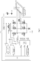
- FIG. 1 is a diagram showing a circuit for detecting an AC leakage current and a DC leakage current according to an embodiment.
- L represents a live wire and N represents a neutral wire.
- the circuit mainly includes an low dropout regulator (LDO) module, a frequency division module, a logic control module, a Metal-Oxide-Semiconductor (MOS) transistor driving module, a leakage current detection coil, a sampling resistor, a programmable gain amplifier (PGA), a gain control module, an analog-to-digital conversion (ADC) module, a digital signal process (DSP), a current limiting module and other modules.
- LDO low dropout regulator
- MOS Metal-Oxide-Semiconductor
- ADC analog-to-digital conversion
- DSP digital signal process
- the LDO module is configured to convert an input power supply voltage into a voltage for driving the leakage current detection coil, and isolate the circuit from another module to avoid a voltage fluctuation of the module affecting the circuit.
- a time period for the coil charging to a saturation zone changes with the change of an amplitude of a driving voltage of the leakage current detection coil, resulting in affecting detection accuracy. Therefore, a stable voltage is required. The voltage can ensure that the leakage current detection coil is in the saturation zone during the DC leakage current detection.
- the frequency division module is configured to divide a frequency of a high-frequency clock signal provided by the DSP or an external crystal oscillator, to control a frequency of an excitation square wave. Since the number of turns of the leakage current detection coil and a magnetic core affect a time period when the coil reaches a bidirectional saturation zone, the frequency of the excitation square wave may be configured by software to improve flexibility of the circuit.
- the main function of the logic control module is to:
- the MOS transistor driving module includes six MOS transistors including MOS transistors M1 to M6.
- the MOS transistors M5 and M6 are turned off, and the MOS transistors M1 to M4 form an H full-bridge.
- the MOS transistors M1 and M4 are turned on, current passing the leakage current detection coil flows through the sampling resistor, a connection point A and a connection point B to the ground GND sequentially.
- the MOS transistors M2 and M3 are turned on, current passing the leakage current detection coil flows through the sampling resistor, the connection point B, the connection point A, to the ground GND sequentially, so as to provide positive and negative excitation square waves for the leakage current detection coil.
- the MOS transistors M5 and M2 are turned on, and MOS transistors M1, M3, M4 and M6 are turned off.
- the leakage current detection coil operates in an electromagnetic induction state, and induced current flows through the MOS transistor M2, the MOS transistor M5, the sampling resistor to the ground GND
- the MOS transistor M5 is turned off and the MOS transistor M6 is turned on, and a half-bridge formed by the MOS transistors M1 and M4 and a half-bridge formed by the MOS transistors M2 and M3 are turned on cyclically.
- the leakage current detection coil generates a self-inspection signal on the sampling resistor by means of inductive shunt.
- FIG. 2 is a diagram showing principles for detecting a DC leakage current and an AC leakage current by time-sharing multiplexing according to the present disclosure.
- a time period t1 is used for detecting a DC leakage current.
- positive and negative excitation square waves are transmitted into the leakage current detection coil, so that a magnetic hysteresis loop of the leakage current detection coil switches back and forth in the bidirectional saturation zone. It is determined whether there is a DC leakage current by detecting a time change of reaching saturation ampere turns.
- a time period t2 is used for detecting an AC leakage current.
- a voltage of the excitation square wave is zero, and the magnetic core operates in a linear zone. It is determined whether there is an AC leakage current by means of electromagnetic induction.
- the leakage current detection coil is configured to detect a residual current between the neutral wire and the live wire, and perform self-inspection on a leakage current detection link through an intermediate self-inspection tap.
- Resistance of the sampling resistor cannot be too large, so as to prevent the magnetic core from entering the saturation zone caused by a large voltage at both terminals of the sampling resistor when it is determined whether there is an AC leakage current by means of electromagnetic induction.
- the resistance of the sampling resistor cannot be too small to ensure detection accuracy of a leakage signal.
- the PGA module is configured to amplify a voltage signal at both terminals of the sampling resistor.
- a magnification of the programmable gain amplifier module may be configured by software to improve the flexibility of the circuit.
- the gain control module is configured to control the magnification of the PGA module in real time.
- the gain control module is required to control the magnification of PGA module in real time according to amplitude of a sampled signal in each sampling cycle, to improve the detection accuracy and make full use of an input voltage range of the ADC module.
- the ADC module is configured to convert a signal amplified by the PGA module from analog to digital.
- the DSP module is configured to process the sampled signal, control the magnification of PGA module, control the operation mode of the logic control module, and respectively process a DC leakage signal, an AC leakage signal and a leakage current self-inspection signal by different algorithms according to different operation modes of the MOS transistor driving module.
- the current limiting module is configured to limit the current flowing through the leakage current detection coil.
- the logic control module controls the output voltage of the pin g3 and the output voltage of the pin g4, so as to control the voltage between the gate and the source of the MOS transistor M3 and the voltage between the gate and the source of the MOS transistor M4, thereby limiting the current.
Landscapes
- Physics & Mathematics (AREA)
- General Physics & Mathematics (AREA)
- Engineering & Computer Science (AREA)
- Power Engineering (AREA)
- Testing Of Short-Circuits, Discontinuities, Leakage, Or Incorrect Line Connections (AREA)
- Testing Of Individual Semiconductor Devices (AREA)
- Emergency Protection Circuit Devices (AREA)
Applications Claiming Priority (2)
| Application Number | Priority Date | Filing Date | Title |
|---|---|---|---|
| CN201910954730.8A CN110531211B (zh) | 2019-10-09 | 2019-10-09 | 一种用于交直流漏电检测系统的电路方案 |
| PCT/CN2020/119325 WO2021068833A1 (fr) | 2019-10-09 | 2020-09-30 | Circuit de détection de fuite de courant alternatif et de courant continu |
Publications (4)
| Publication Number | Publication Date |
|---|---|
| EP4024059A1 true EP4024059A1 (fr) | 2022-07-06 |
| EP4024059A4 EP4024059A4 (fr) | 2022-11-16 |
| EP4024059B1 EP4024059B1 (fr) | 2023-08-23 |
| EP4024059C0 EP4024059C0 (fr) | 2023-08-23 |
Family
ID=68671478
Family Applications (1)
| Application Number | Title | Priority Date | Filing Date |
|---|---|---|---|
| EP20875192.5A Active EP4024059B1 (fr) | 2019-10-09 | 2020-09-30 | Circuit de détection de fuite de courant alternatif et de courant continu |
Country Status (5)
| Country | Link |
|---|---|
| US (1) | US11977130B2 (fr) |
| EP (1) | EP4024059B1 (fr) |
| CN (1) | CN110531211B (fr) |
| CA (1) | CA3153758C (fr) |
| WO (1) | WO2021068833A1 (fr) |
Families Citing this family (10)
| Publication number | Priority date | Publication date | Assignee | Title |
|---|---|---|---|---|
| CN110531211B (zh) | 2019-10-09 | 2021-10-29 | 青岛鼎信通讯股份有限公司 | 一种用于交直流漏电检测系统的电路方案 |
| CN110927623A (zh) * | 2019-12-06 | 2020-03-27 | 国网江苏省电力有限公司南通供电分公司 | 一种电力设备漏电检测系统 |
| CN111856119A (zh) * | 2020-08-24 | 2020-10-30 | 上海煜闻电子科技有限公司 | 一种漏电流检测装置和检测方法 |
| CN113612195B (zh) * | 2021-08-06 | 2024-04-09 | 浙江天正电气股份有限公司 | 一种剩余电流保护装置、电子设备及信号控制方法 |
| CN114512954B (zh) * | 2021-09-13 | 2025-04-22 | 上海正泰智能科技有限公司 | 检测电路、检测方法及断路器 |
| CN113809716B (zh) * | 2021-09-25 | 2023-09-15 | 浙江巨磁智能技术有限公司 | 一种纯硬件化实现的b型漏电保护方法 |
| CN114337616B (zh) * | 2021-12-06 | 2026-03-03 | 宁波大学 | 一种适用于数字ldo的时钟产生电路 |
| CN115267599A (zh) * | 2022-07-22 | 2022-11-01 | 江阴信邦电子有限公司 | 一种充电装置b型漏电测试系统 |
| CN116774101B (zh) * | 2023-08-21 | 2023-10-27 | 保定传能电子科技有限公司 | 一种低压线路漏电流检测装置 |
| CN119916075B (zh) * | 2025-04-03 | 2025-07-01 | 上海盛位电子技术有限公司 | 一种复合电流检测传感器 |
Family Cites Families (17)
| Publication number | Priority date | Publication date | Assignee | Title |
|---|---|---|---|---|
| CN201466675U (zh) * | 2009-06-25 | 2010-05-12 | 黄华道 | 漏电检测保护电路 |
| CN201449415U (zh) | 2009-07-13 | 2010-05-05 | 珠海市澳特尔测控仪表有限公司 | 交直流漏电流传感器 |
| US8098696B2 (en) * | 2009-09-04 | 2012-01-17 | Rosemount Inc. | Detection and compensation of multiplexer leakage current |
| AT511285B1 (de) | 2011-04-01 | 2019-11-15 | Eaton Gmbh | Fehlerstromschutzschalter |
| CN202486253U (zh) | 2012-03-12 | 2012-10-10 | 深圳和而泰智能控制股份有限公司 | 漏电检测电路及其装置 |
| CN103424643B (zh) * | 2012-05-22 | 2017-09-12 | 浙江巨磁智能技术有限公司 | 接地故障检测装置 |
| JP5615335B2 (ja) * | 2012-10-15 | 2014-10-29 | オムロンオートモーティブエレクトロニクス株式会社 | 漏電検知装置 |
| CN104749424A (zh) * | 2015-03-05 | 2015-07-01 | 青岛鼎信通讯股份有限公司 | 一种基于电压电流矢量关系的剩余电流检测方法 |
| JP2017188681A (ja) * | 2016-03-31 | 2017-10-12 | 株式会社豊田自動織機 | 車載用の電力変換装置 |
| KR102539688B1 (ko) | 2016-04-28 | 2023-06-07 | 엘에스일렉트릭(주) | 누전 차단기 |
| DE102016216401A1 (de) | 2016-08-31 | 2018-03-01 | Siemens Aktiengesellschaft | Verfahren zum Laden eines elektrisch betriebenen Fahrzeuges mit Hilfe eines Ladekabels, Ladekabel und Fehlerstrom-Schutzschaltung zur Detektion eines Gleichstroms |
| CN106443305A (zh) * | 2016-11-09 | 2017-02-22 | 广东盈科电子有限公司 | 一种交流电的漏电检测电路及检测方法 |
| JP6697746B2 (ja) * | 2016-11-29 | 2020-05-27 | パナソニックIpマネジメント株式会社 | 漏電検出装置 |
| CN110224378B (zh) | 2018-03-02 | 2023-01-10 | 西门子公司 | 故障电流保护单元和方法 |
| CN108963972B (zh) * | 2018-08-02 | 2020-02-18 | 杭州中恒电气股份有限公司 | 一种具有智能恢复功能的交流漏电保护电路 |
| CN109406932B (zh) * | 2018-11-02 | 2020-08-25 | 罗孚电气(厦门)有限公司 | 漏电检测装置及系统 |
| CN110531211B (zh) * | 2019-10-09 | 2021-10-29 | 青岛鼎信通讯股份有限公司 | 一种用于交直流漏电检测系统的电路方案 |
-
2019
- 2019-10-09 CN CN201910954730.8A patent/CN110531211B/zh active Active
-
2020
- 2020-09-30 CA CA3153758A patent/CA3153758C/fr active Active
- 2020-09-30 US US17/767,892 patent/US11977130B2/en active Active
- 2020-09-30 WO PCT/CN2020/119325 patent/WO2021068833A1/fr not_active Ceased
- 2020-09-30 EP EP20875192.5A patent/EP4024059B1/fr active Active
Also Published As
| Publication number | Publication date |
|---|---|
| CA3153758A1 (fr) | 2021-04-15 |
| WO2021068833A1 (fr) | 2021-04-15 |
| EP4024059B1 (fr) | 2023-08-23 |
| CN110531211B (zh) | 2021-10-29 |
| CA3153758C (fr) | 2023-10-10 |
| US20240085495A1 (en) | 2024-03-14 |
| CN110531211A (zh) | 2019-12-03 |
| EP4024059A4 (fr) | 2022-11-16 |
| EP4024059C0 (fr) | 2023-08-23 |
| US11977130B2 (en) | 2024-05-07 |
Similar Documents
| Publication | Publication Date | Title |
|---|---|---|
| EP4024059B1 (fr) | Circuit de détection de fuite de courant alternatif et de courant continu | |
| US11581757B2 (en) | Wireless power transfer system and method | |
| EP3121921B1 (fr) | Dispositif de protection contre le courant résiduel | |
| JPWO2017134870A1 (ja) | 電力変換装置および非接触給電システム | |
| EP1610133B1 (fr) | Appareil de mesure de courant alternatif et/ou continu | |
| JP2014180200A (ja) | 電力変換器コントローラ、電力変換器、および電力変換器の入力を検知するための方法 | |
| US11668762B2 (en) | Leakage current detection circuit, method and leakage current detector | |
| Sun et al. | Auxiliary power network architecture for 10 kv sic-based power electronics building blocks | |
| JP2016220483A (ja) | 共振形電源装置 | |
| CN107422165A (zh) | 可在线退磁的闭环霍尔电流传感器 | |
| CN119483192B (zh) | 一种功率变换器及其控制方法 | |
| US8198850B2 (en) | DC motor drive | |
| CN113852218A (zh) | 用于无线功率传输系统的物体检测设备和方法 | |
| CN1945948B (zh) | 功率转换器的同步整流电路 | |
| CN100438285C (zh) | 频率受控的功率因数校正电路和方法 | |
| SU1053167A1 (ru) | Устройство дл намагничивани и размагничивани | |
| JPH0293375A (ja) | 電流検出回路 | |
| EP3767788A1 (fr) | Dispositifdispositif d'éclairage d'urgence | |
| SU1610285A1 (ru) | Электромагнитный расходомер | |
| TW202603377A (zh) | 閉迴路電流感測器及其操作方法 | |
| KR100284435B1 (ko) | 유도가열밥솥의 전력제어장치 | |
| SU1705774A1 (ru) | Устройство дл обнаружени повреждени межвитковой изол ции в электрических катушках | |
| SU1677651A1 (ru) | Устройство дл измерени параметров многополюсников на посто нном токе | |
| JPH07191066A (ja) | 絶縁形電圧検出器 | |
| Periale et al. | Magnetic field behavior of HV and LV systems for the LHC experiments |
Legal Events
| Date | Code | Title | Description |
|---|---|---|---|
| STAA | Information on the status of an ep patent application or granted ep patent |
Free format text: STATUS: THE INTERNATIONAL PUBLICATION HAS BEEN MADE |
|
| PUAI | Public reference made under article 153(3) epc to a published international application that has entered the european phase |
Free format text: ORIGINAL CODE: 0009012 |
|
| STAA | Information on the status of an ep patent application or granted ep patent |
Free format text: STATUS: REQUEST FOR EXAMINATION WAS MADE |
|
| 17P | Request for examination filed |
Effective date: 20220331 |
|
| AK | Designated contracting states |
Kind code of ref document: A1 Designated state(s): AL AT BE BG CH CY CZ DE DK EE ES FI FR GB GR HR HU IE IS IT LI LT LU LV MC MK MT NL NO PL PT RO RS SE SI SK SM TR |
|
| A4 | Supplementary search report drawn up and despatched |
Effective date: 20221014 |
|
| RIC1 | Information provided on ipc code assigned before grant |
Ipc: G01R 19/00 20060101ALI20221010BHEP Ipc: G01R 15/18 20060101ALI20221010BHEP Ipc: H02H 3/33 20060101ALI20221010BHEP Ipc: G01R 31/52 20200101AFI20221010BHEP |
|
| DAV | Request for validation of the european patent (deleted) | ||
| DAX | Request for extension of the european patent (deleted) | ||
| REG | Reference to a national code |
Ref country code: DE Ref legal event code: R079 Free format text: PREVIOUS MAIN CLASS: G01R0031000000 Ipc: G01R0031520000 Ref document number: 602020016434 Country of ref document: DE |
|
| RIC1 | Information provided on ipc code assigned before grant |
Ipc: G01R 19/00 20060101ALI20230125BHEP Ipc: G01R 15/18 20060101ALI20230125BHEP Ipc: H02H 3/33 20060101ALI20230125BHEP Ipc: G01R 31/52 20200101AFI20230125BHEP |
|
| GRAP | Despatch of communication of intention to grant a patent |
Free format text: ORIGINAL CODE: EPIDOSNIGR1 |
|
| STAA | Information on the status of an ep patent application or granted ep patent |
Free format text: STATUS: GRANT OF PATENT IS INTENDED |
|
| INTG | Intention to grant announced |
Effective date: 20230314 |
|
| GRAS | Grant fee paid |
Free format text: ORIGINAL CODE: EPIDOSNIGR3 |
|
| GRAA | (expected) grant |
Free format text: ORIGINAL CODE: 0009210 |
|
| STAA | Information on the status of an ep patent application or granted ep patent |
Free format text: STATUS: THE PATENT HAS BEEN GRANTED |
|
| AK | Designated contracting states |
Kind code of ref document: B1 Designated state(s): AL AT BE BG CH CY CZ DE DK EE ES FI FR GB GR HR HU IE IS IT LI LT LU LV MC MK MT NL NO PL PT RO RS SE SI SK SM TR |
|
| REG | Reference to a national code |
Ref country code: GB Ref legal event code: FG4D |
|
| REG | Reference to a national code |
Ref country code: CH Ref legal event code: EP |
|
| REG | Reference to a national code |
Ref country code: IE Ref legal event code: FG4D |
|
| REG | Reference to a national code |
Ref country code: DE Ref legal event code: R096 Ref document number: 602020016434 Country of ref document: DE |
|
| U01 | Request for unitary effect filed |
Effective date: 20230918 |
|
| U07 | Unitary effect registered |
Designated state(s): AT BE BG DE DK EE FI FR IT LT LU LV MT NL PT SE SI Effective date: 20230922 |
|
| U20 | Renewal fee for the european patent with unitary effect paid |
Year of fee payment: 4 Effective date: 20231123 |
|
| PG25 | Lapsed in a contracting state [announced via postgrant information from national office to epo] |
Ref country code: GR Free format text: LAPSE BECAUSE OF FAILURE TO SUBMIT A TRANSLATION OF THE DESCRIPTION OR TO PAY THE FEE WITHIN THE PRESCRIBED TIME-LIMIT Effective date: 20231124 |
|
| PG25 | Lapsed in a contracting state [announced via postgrant information from national office to epo] |
Ref country code: IS Free format text: LAPSE BECAUSE OF FAILURE TO SUBMIT A TRANSLATION OF THE DESCRIPTION OR TO PAY THE FEE WITHIN THE PRESCRIBED TIME-LIMIT Effective date: 20231223 |
|
| PG25 | Lapsed in a contracting state [announced via postgrant information from national office to epo] |
Ref country code: RS Free format text: LAPSE BECAUSE OF FAILURE TO SUBMIT A TRANSLATION OF THE DESCRIPTION OR TO PAY THE FEE WITHIN THE PRESCRIBED TIME-LIMIT Effective date: 20230823 Ref country code: NO Free format text: LAPSE BECAUSE OF FAILURE TO SUBMIT A TRANSLATION OF THE DESCRIPTION OR TO PAY THE FEE WITHIN THE PRESCRIBED TIME-LIMIT Effective date: 20231123 Ref country code: IS Free format text: LAPSE BECAUSE OF FAILURE TO SUBMIT A TRANSLATION OF THE DESCRIPTION OR TO PAY THE FEE WITHIN THE PRESCRIBED TIME-LIMIT Effective date: 20231223 Ref country code: HR Free format text: LAPSE BECAUSE OF FAILURE TO SUBMIT A TRANSLATION OF THE DESCRIPTION OR TO PAY THE FEE WITHIN THE PRESCRIBED TIME-LIMIT Effective date: 20230823 Ref country code: GR Free format text: LAPSE BECAUSE OF FAILURE TO SUBMIT A TRANSLATION OF THE DESCRIPTION OR TO PAY THE FEE WITHIN THE PRESCRIBED TIME-LIMIT Effective date: 20231124 |
|
| PG25 | Lapsed in a contracting state [announced via postgrant information from national office to epo] |
Ref country code: PL Free format text: LAPSE BECAUSE OF FAILURE TO SUBMIT A TRANSLATION OF THE DESCRIPTION OR TO PAY THE FEE WITHIN THE PRESCRIBED TIME-LIMIT Effective date: 20230823 |
|
| PG25 | Lapsed in a contracting state [announced via postgrant information from national office to epo] |
Ref country code: ES Free format text: LAPSE BECAUSE OF FAILURE TO SUBMIT A TRANSLATION OF THE DESCRIPTION OR TO PAY THE FEE WITHIN THE PRESCRIBED TIME-LIMIT Effective date: 20230823 |
|
| PG25 | Lapsed in a contracting state [announced via postgrant information from national office to epo] |
Ref country code: SM Free format text: LAPSE BECAUSE OF FAILURE TO SUBMIT A TRANSLATION OF THE DESCRIPTION OR TO PAY THE FEE WITHIN THE PRESCRIBED TIME-LIMIT Effective date: 20230823 Ref country code: RO Free format text: LAPSE BECAUSE OF FAILURE TO SUBMIT A TRANSLATION OF THE DESCRIPTION OR TO PAY THE FEE WITHIN THE PRESCRIBED TIME-LIMIT Effective date: 20230823 Ref country code: ES Free format text: LAPSE BECAUSE OF FAILURE TO SUBMIT A TRANSLATION OF THE DESCRIPTION OR TO PAY THE FEE WITHIN THE PRESCRIBED TIME-LIMIT Effective date: 20230823 Ref country code: CZ Free format text: LAPSE BECAUSE OF FAILURE TO SUBMIT A TRANSLATION OF THE DESCRIPTION OR TO PAY THE FEE WITHIN THE PRESCRIBED TIME-LIMIT Effective date: 20230823 Ref country code: SK Free format text: LAPSE BECAUSE OF FAILURE TO SUBMIT A TRANSLATION OF THE DESCRIPTION OR TO PAY THE FEE WITHIN THE PRESCRIBED TIME-LIMIT Effective date: 20230823 |
|
| REG | Reference to a national code |
Ref country code: CH Ref legal event code: PL |
|
| REG | Reference to a national code |
Ref country code: DE Ref legal event code: R097 Ref document number: 602020016434 Country of ref document: DE |
|
| PG25 | Lapsed in a contracting state [announced via postgrant information from national office to epo] |
Ref country code: MC Free format text: LAPSE BECAUSE OF FAILURE TO SUBMIT A TRANSLATION OF THE DESCRIPTION OR TO PAY THE FEE WITHIN THE PRESCRIBED TIME-LIMIT Effective date: 20230823 |
|
| PLBE | No opposition filed within time limit |
Free format text: ORIGINAL CODE: 0009261 |
|
| STAA | Information on the status of an ep patent application or granted ep patent |
Free format text: STATUS: NO OPPOSITION FILED WITHIN TIME LIMIT |
|
| REG | Reference to a national code |
Ref country code: IE Ref legal event code: MM4A |
|
| PG25 | Lapsed in a contracting state [announced via postgrant information from national office to epo] |
Ref country code: IE Free format text: LAPSE BECAUSE OF NON-PAYMENT OF DUE FEES Effective date: 20230930 |
|
| PG25 | Lapsed in a contracting state [announced via postgrant information from national office to epo] |
Ref country code: CH Free format text: LAPSE BECAUSE OF NON-PAYMENT OF DUE FEES Effective date: 20230930 |
|
| 26N | No opposition filed |
Effective date: 20240524 |
|
| PG25 | Lapsed in a contracting state [announced via postgrant information from national office to epo] |
Ref country code: IE Free format text: LAPSE BECAUSE OF NON-PAYMENT OF DUE FEES Effective date: 20230930 Ref country code: CH Free format text: LAPSE BECAUSE OF NON-PAYMENT OF DUE FEES Effective date: 20230930 |
|
| U20 | Renewal fee for the european patent with unitary effect paid |
Year of fee payment: 5 Effective date: 20240925 |
|
| PG25 | Lapsed in a contracting state [announced via postgrant information from national office to epo] |
Ref country code: CY Free format text: LAPSE BECAUSE OF FAILURE TO SUBMIT A TRANSLATION OF THE DESCRIPTION OR TO PAY THE FEE WITHIN THE PRESCRIBED TIME-LIMIT; INVALID AB INITIO Effective date: 20200930 |
|
| PG25 | Lapsed in a contracting state [announced via postgrant information from national office to epo] |
Ref country code: HU Free format text: LAPSE BECAUSE OF FAILURE TO SUBMIT A TRANSLATION OF THE DESCRIPTION OR TO PAY THE FEE WITHIN THE PRESCRIBED TIME-LIMIT; INVALID AB INITIO Effective date: 20200930 |
|
| PGFP | Annual fee paid to national office [announced via postgrant information from national office to epo] |
Ref country code: GB Payment date: 20250919 Year of fee payment: 6 |
|
| U20 | Renewal fee for the european patent with unitary effect paid |
Year of fee payment: 6 Effective date: 20250924 |
|
| PG25 | Lapsed in a contracting state [announced via postgrant information from national office to epo] |
Ref country code: TR Free format text: LAPSE BECAUSE OF FAILURE TO SUBMIT A TRANSLATION OF THE DESCRIPTION OR TO PAY THE FEE WITHIN THE PRESCRIBED TIME-LIMIT Effective date: 20230823 |