EP4024074A1 - Durchsetzung der datenkonsistenz bei der tiefenlernbildrekonstruktion von magnetresonanzbildern - Google Patents
Durchsetzung der datenkonsistenz bei der tiefenlernbildrekonstruktion von magnetresonanzbildern Download PDFInfo
- Publication number
- EP4024074A1 EP4024074A1 EP21150346.1A EP21150346A EP4024074A1 EP 4024074 A1 EP4024074 A1 EP 4024074A1 EP 21150346 A EP21150346 A EP 21150346A EP 4024074 A1 EP4024074 A1 EP 4024074A1
- Authority
- EP
- European Patent Office
- Prior art keywords
- space
- image
- data
- source data
- reconstruction algorithm
- Prior art date
- Legal status (The legal status is an assumption and is not a legal conclusion. Google has not performed a legal analysis and makes no representation as to the accuracy of the status listed.)
- Withdrawn
Links
Images



Classifications
-
- G—PHYSICS
- G06—COMPUTING OR CALCULATING; COUNTING
- G06T—IMAGE DATA PROCESSING OR GENERATION, IN GENERAL
- G06T12/00—Tomographic reconstruction from projections
- G06T12/30—Image post-processing, e.g. metal artefact correction
-
- G—PHYSICS
- G01—MEASURING; TESTING
- G01R—MEASURING ELECTRIC VARIABLES; MEASURING MAGNETIC VARIABLES
- G01R33/00—Arrangements or instruments for measuring magnetic variables
- G01R33/20—Arrangements or instruments for measuring magnetic variables involving magnetic resonance
- G01R33/44—Arrangements or instruments for measuring magnetic variables involving magnetic resonance using nuclear magnetic resonance [NMR]
- G01R33/48—NMR imaging systems
- G01R33/54—Signal processing systems, e.g. using pulse sequences ; Generation or control of pulse sequences; Operator console
- G01R33/56—Image enhancement or correction, e.g. subtraction or averaging techniques, e.g. improvement of signal-to-noise ratio and resolution
- G01R33/5608—Data processing and visualization specially adapted for MR, e.g. for feature analysis and pattern recognition on the basis of measured MR data, segmentation of measured MR data, edge contour detection on the basis of measured MR data, for enhancing measured MR data in terms of signal-to-noise ratio by means of noise filtering or apodization, for enhancing measured MR data in terms of resolution by means for deblurring, windowing, zero filling, or generation of gray-scaled images, colour-coded images or images displaying vectors instead of pixels
-
- G—PHYSICS
- G06—COMPUTING OR CALCULATING; COUNTING
- G06N—COMPUTING ARRANGEMENTS BASED ON SPECIFIC COMPUTATIONAL MODELS
- G06N3/00—Computing arrangements based on biological models
- G06N3/02—Neural networks
- G06N3/04—Architecture, e.g. interconnection topology
-
- G—PHYSICS
- G06—COMPUTING OR CALCULATING; COUNTING
- G06N—COMPUTING ARRANGEMENTS BASED ON SPECIFIC COMPUTATIONAL MODELS
- G06N3/00—Computing arrangements based on biological models
- G06N3/02—Neural networks
- G06N3/04—Architecture, e.g. interconnection topology
- G06N3/0464—Convolutional networks [CNN, ConvNet]
-
- G—PHYSICS
- G06—COMPUTING OR CALCULATING; COUNTING
- G06N—COMPUTING ARRANGEMENTS BASED ON SPECIFIC COMPUTATIONAL MODELS
- G06N3/00—Computing arrangements based on biological models
- G06N3/02—Neural networks
- G06N3/08—Learning methods
- G06N3/09—Supervised learning
-
- G—PHYSICS
- G16—INFORMATION AND COMMUNICATION TECHNOLOGY [ICT] SPECIALLY ADAPTED FOR SPECIFIC APPLICATION FIELDS
- G16H—HEALTHCARE INFORMATICS, i.e. INFORMATION AND COMMUNICATION TECHNOLOGY [ICT] SPECIALLY ADAPTED FOR THE HANDLING OR PROCESSING OF MEDICAL OR HEALTHCARE DATA
- G16H30/00—ICT specially adapted for the handling or processing of medical images
- G16H30/40—ICT specially adapted for the handling or processing of medical images for processing medical images, e.g. editing
-
- G—PHYSICS
- G06—COMPUTING OR CALCULATING; COUNTING
- G06N—COMPUTING ARRANGEMENTS BASED ON SPECIFIC COMPUTATIONAL MODELS
- G06N3/00—Computing arrangements based on biological models
- G06N3/02—Neural networks
- G06N3/08—Learning methods
- G06N3/084—Backpropagation, e.g. using gradient descent
Definitions
- Various examples generally relate to image reconstruction. Various examples specifically relate to enforcing data consistency in connection with the image reconstruction.
- Image reconstruction is used for various use cases. Examples include increasing an image resolution and reducing artifacts or noise included in an image.
- image reconstruction can be used for medical image datasets.
- Image reconstruction can also be used for post-processing microscopy images or movie clips.
- reconstruction algorithms are known.
- One example type of reconstruction algorithm employs machine learning.
- Such machine-learned reconstruction algorithms often show improved image quality compared to traditional re-construction techniques, however, one of the limitations is the risk of hallucinating structures, or other stability issues such as e.g., an unpredicted behavior when an input is too different from what the network has been trained on, which is of special concern for medical image application.
- GANs generative adversarial networks
- DCO data-consistency operation
- a reconstruction algorithm is used to determine a reconstructed image.
- a DCO - that may be embedded into the reconstruction algorithm or may be separately defined - is applied to the reconstructed image, to thereby enforce a consistency between an input image that is defined by an input dataset, as well as the reconstructed image.
- the DCO may also be termed data-fidelity operation or forward-sampling operation.
- the DCOs described herein facilitate accurate reconstruction with little or no artifacts stemming from the reconstruction algorithm itself.
- the DCOs described herein are computationally inexpensive.
- the DCO determines, for multiple K-space positions at which the input dataset includes respective source data, a contribution of respective K-space values associated with the input dataset to a K-space representation of the reconstructed image.
- the DCO can, at least to a certain degree, override or undo contributions of the reconstruction algorithm, so that at K-space positions where source data is available, the respective values of the K-space representation of the reconstructed image obtained from the reconstruction algorithm are replaced fully or partly by respective values of the source data.
- the reconstructed image obtained from the reconstruction algorithm prior to the DCO can be labelled preliminary reconstructed image or pre-DCO reconstructed image; and the reconstructed image obtained after applying the DCO is the final reconstructed image or post-DCO reconstructed image.
- this source data can prevail in the final reconstructed image or, at least, significantly contribute to the K-space values of the K-space representation of the final reconstructed image.
- the source data is not available in the input dataset, no contribution of respective K-space values associated with the input dataset may be made to the K-space representation of the final reconstructed image.
- a machine-learned reconstruction algorithm is trained using a loss function.
- the loss function is based on a difference between a ground truth image and the reference image.
- the reference image is determined based on a training dataset that is associated with the ground truth image and using the machine-learned reconstruction image.
- the reference image is further determined based on executing a data-consistency operation.
- the data-consistency operation determines, for multiple K-space positions at which the training dataset comprises respective source data, a contribution of respective K-space-values associated with the training dataset to a K-space representation of the reference image.
- the machine-learned reconstruction image can be accurately trained, in particular, taking into consideration alterations to its output made by the data-consistency operation. For example, spatial frequencies in the reference image that are modified by the contribution determined by the data-consistency operation may not be overemphasized in the training process. The training can focus on other spatial frequencies not modified by the contribution determined by the data-consistency operation.
- circuits and other electrical devices generally provide for a plurality of circuits or other electrical devices. All references to the circuits and other electrical devices and the functionality provided by each are not intended to be limited to encompassing only what is illustrated and described herein. While particular labels may be assigned to the various circuits or other electrical devices disclosed, such labels are not intended to limit the scope of operation for the circuits and the other electrical devices. Such circuits and other electrical devices may be combined with each other and/or separated in any manner based on the particular type of electrical implementation that is desired.
- any circuit or other electrical device disclosed herein may include any number of microcontrollers, a graphics processor unit (GPU), integrated circuits, memory devices (e.g., FLASH, random access memory (RAM), read only memory (ROM), electrically programmable read only memory (EPROM), electrically erasable programmable read only memory (EEPROM), or other suitable variants thereof), and software which co-act with one another to perform operation(s) disclosed herein.
- any one or more of the electrical devices may be configured to execute a program code that is embodied in a non-transitory computer readable medium programmed to perform any number of the functions as disclosed.
- Various examples of the disclosure generally relate to image reconstruction.
- An input dataset is obtained.
- the techniques described herein can be applicable to various image reconstruction tasks. For instance, image reconstruction of medical images, e.g., MRI image or computer tomography (CT) images would be possible.
- CT computer tomography
- Microscopy images could be reconstructed, e.g., to achieve super resolution and/or remove artifacts.
- Photography is could be reconstructed, e.g., to remove flares.
- X-ray images could be reconstructed, e.g., to make certain structures otherwise hidden visible.
- the input dataset can be obtained from a data storage.
- the input dataset can be obtained from a measurement device, e.g., a multi-pixel detector, radio-frequency receivers, etc..
- the input dataset can include source data.
- the source data could be implemented by K-space data samples or by image-domain pixels or voxels.
- the input dataset defines an input image.
- the input dataset may include the input image.
- the input dataset may be defined in spatial domain.
- an optical microscope may be used to obtain the input image.
- the input dataset may be defined in K-space. Examples would include acquisition of a magnetic resonance imaging (MRI) measurement dataset.
- MRI magnetic resonance imaging
- a Fourier transformation is required to obtain the input image from the input dataset.
- Example input datasets include source data such as raw measurement in an MRI K-space-to-image reconstruction, or e.g., a low-resolution image in the case of a super-resolution image-to-image reconstruction.
- the particular type of the reconstruction algorithm is not germane for the functioning of the techniques described herein; in other words, the techniques described herein can be flexibly combined with various kinds and types of reconstruction algorithms.
- different types of reconstruction algorithms may be appropriate to use.
- a respective image reconstruction algorithm may be used, e.g., correcting aberrations introduced by the objective lens, creating super-resolution, etc..
- a respective image reconstruction algorithm tailored to this task may be used.
- a machine-learned reconstruction algorithm may be used. Examples would include variational or unrolled networks for reconstruction of undersampled MRI measurement data, see, e.g., Hammernik, Kerstin, et al. "Learning a variational network for reconstruction of accelerated MRI data.” Magnetic resonance in medicine 79.6 (2018): 3055-3071 . Another example would be GANs or AUTOMAP algorithms, as described above.
- a DCO is used, to thereby enforce a consistency between the reconstructed image and the input image defined by the input dataset.
- the preliminary reconstructed image obtained from the image reconstruction algorithm may be altered or amended, at least at certain positions in image domain or in K-space (i.e., for certain spatial frequencies), when applying the DCO.
- altering or amending of the data underlying the preliminary reconstructed image can be done to increase a similarity value between the input image and the final reconstructed image.
- the quality of the image reconstruction can be increased.
- the DCOs described herein can operate in K-space. I.e., different K-space positions may be treated differently by the DCO. Different spatial frequencies may be affected differently by the DCO.
- the DCO determines, for multiple K-space positions at which the input dataset includes respective source data (e.g., measurement data or generally data that is initially available before applying any reconstruction), a contribution of respective K-space values associated with the input dataset to a K-space representation of the reconstructed image.
- source data e.g., measurement data or generally data that is initially available before applying any reconstruction
- the DCO can select, for each one of the multiple K-space positions where source data is natively available, to include the respective source data in the reconstructed image, at least to a certain degree.
- the DCO may be defined separately from the reconstruction algorithm or may be integrated into the reconstruction algorithm.
- the DCO can be applied in each iteration.
- each layer of the unrolled neural network may be followed by applying the DCO.
- the input dataset is natively defined in the K-space and the available source data includes the acquired K-space values.
- the source data or more specifically the input image included in the input dataset is transformed to K-space, to obtain the K-space representation of the input image; here, it is possible to provide a mask indicating the K-space positions natively included as or defined by the source data to the DCO.
- Natively included could mean, e.g., for an input image such K-space positions captured by the input image up to a cut-off spatial frequency defined by Nyquist's theorem.
- K-space values can be selected from the K-space representation of the input image by the DCO within the mask.
- the mask includes all the K-space positions of the input low-resolution image. If there is partial Fourier, only the acquired measurements defining the source data will be included in the mask.
- the reconstruction can have an increased stability and robustness.
- the hard DCO according to Eq. 2 would ensure that the reconstruction algorithm only changes the high spatial frequencies in the reconstructed image vis-á-vis the input image, which high spatial frequency are not available in the source data of the input dataset defining the input image.
- the reconstruction would not change the low spatial frequencies where most of the energy of the input image and the reconstructed image is located.
- the low spatial frequencies are fixed, so that it is not possible to add something that was not present in the original input image or remove something that was present in the original input image in this frequency band.
- the DCO can be summarized with the following pseudo code where y is the input of the DCO (i.e., the pre-DCO reconstructed image; which may be labeled a preliminary reconstructed image) and y its output (i.e., the post-DCO final reconstructed image), X is the K-space representation of the input image using zero-padding so that the size of X matches the size of the K-space representation of y (denoted Y), mask being a binary matrix the size of Y with ones where the source data is available from the input dataset and zero when not: Y ⁇ FFT y Y ⁇ where mask X Y y ⁇ ⁇ IFFT Y
- FFT fast Fourier transformation
- IFFT inverse fast Fourier transformation
- out i ⁇ m i if condition i n i otherwise I.e., where(mask,X,Y) returns a tensor of elements selected from either X or Y, depending on the mask value.
- the contribution determined by the DCO replaces, for each one of the multiple K-space positions for which the input dataset comprises respective source data (i.e., inside the mask), a further respective K-space value provided by the reconstruction algorithm (i.e., the respective element of the preliminary reconstructed image Y) by the respective K-space value associated with the input dataset (i.e., with the respective element of X).
- Such operation according to Eq. can be labeled as "hard" DCO, because it is a binary selection between either the K-space value of the source data or the K-space value of the K-space representation of the preliminary reconstructed image.
- the weighting parameter ⁇ defines a weighted combination of the K-space value associated with the input dataset (i.e., X) and a respective further K-space value provided by the reconstruction algorithm (i.e., the preliminary reconstructed image Y), according to Eq. 4.
- the weighting parameter is configured to suppress the respective further K-space values if compared to the respective K-space value, as evidenced by the subtraction of Eq. 4.
- the weighting parameter ⁇ may be predefined. It would also be possible that the weighting parameter is trained using machine-learning techniques. For instance, the weighting parameter may be trained end-to-end together with the reconstruction algorithm. I.e., while varying weights of the reconstruction algorithm, it is possible to also vary the value of the weighting parameter.
- the value of the weighting parameter varies as a function of the multiple K-space positions. I.e., it would be possible that depending on the particular K-space position, a different value of the weighting parameter is used. In other examples, the value of the weighting parameter may be fixed, i.e., not vary as a function of the K-space position.
- the transition regime may be located at the edge of the mask, i.e., at the edge of the regime of multiple K-space positions for which the input dataset includes source data.
- the transition regime may be located at the edge of the mask, i.e., at the edge of the regime of multiple K-space positions for which the input dataset includes source data.
- TAB. 1 Examples of image reconstruction algorithms. Brief description Example details I Classic reconstruction algorithm A manually parameterized reconstruction algorithm may be used. For instance, such reconstruction algorithm may rely on operations such as interpolation, edge sharpening, contrast enhancement, low-/high-pass filtering, blurring operations, etc. to name just a few options.
- the DCO can be sequentially applied, after the reconstruction algorithm II Machine-learned reconstruction algorithm For instance, it would be possible to use a neural network to implement the reconstruction algorithm. For example, if the reconstruction algorithm is implemented as a multi-layer deep neural network, it would be possible that one or more layers towards the output layer or even the output layer itself implement the DCO.
- a layer at the end of the multi-layer deep neural network may be added to implement the DCO; this DCO-layer may transform the input of that layer into K-space and then replace all the values at those K-space positions for which there is a corresponding source data available in the input dataset being input into the input layer of the multi-layer deep neural network.
- source data may be natively defined in K-space. It would also be possible to determine the K-space representation of the input image to determine these values. In either case, a skip connection from the input of the multi-layer deep neural network to the DCI-layer may be implemented.
- the DCO layer can transform the result of this operation back to the image domain.
- weights of each layer of the neural network may be set.
- ground truth data defining a reference reconstructed image of high quality. For instance, it would be possible to obtain the input image by artificially downsampling or otherwise preprocessing the reference reconstructed image. Noise or artifacts could be synthesized.
- the machine-learned reconstruction algorithm may be trained end-to-end including the DCO, so during the training process the machine-learned reconstruction algorithm is not required to learn to reconstruct the low spatial frequencies and could then use all of its capacity to only focus in predicting the high spatial frequencies, i.e. a much simpler task for which less training data are needed to obtain a satisfying generalization. This can increase the accuracy.
- III Iterative optimization The iterative optimization can include multiple iterations, e.g., so-called Landweber iterations. Other examples include prima-dual or alternating direction method of multipliers. Thereby, a gradient descent optimization can be implemented. By means of the iterative optimization, it is possible to maximize or minimize a respective goal function that defines the reconstructed image.
- the multiple iterations can yield a sequence of (temporary) images.
- Each iteration can include a regularization operation and the DCO.
- the DCO can be implemented by an appropriately configured forward-measurement model.
- the DCO executed in a given iteration is based on difference between the K-space source data and synthesized K-space source data of that respective iteration.
- the synthesized K-space source data is based on a K-space representation of a prior image of the sequence of images and the forward-measurement model.
- the forward-measurement model can then suppress contributions to the synthesized K-space source data at K-space positions at which the K-space source data has been sampled using the undersampling trajectory, to thereby implement the DCO.
- such techniques can be used to implement a reconstruction algorithm to reconstruct an MRI image based on an input dataset including K-space source data that is undersampled in accordance with a respective undersampling trajectory.
- Acquisition of MRI data can require significant time.
- K-space To accelerate the data acquisition, it is known to undersample K-space. Missing data can be reconstructed (MRI reconstruction).
- MRI reconstruction Various techniques for implementing MRI reconstruction are known.
- One prior art technique is referred to as compressed sensing. See, e.g., Lustig, Michael, David Donoho, and John M. Pauly.
- a classic formulation of the regularization operation is based on sparsity of the MRI image in a transform domain such as a wavelet domain in combination with pseudorandom sampling that can introduce aliasing artifacts that are incoherent in the respective transform domain.
- a transform domain such as a wavelet domain
- pseudorandom sampling that can introduce aliasing artifacts that are incoherent in the respective transform domain.
- Another example would be a Fourier domain, in particular for acquisitions of a dynamically moving target.
- Another example would be total variation (TV) used in connection with non-Cartesian K-space trajectories such as radial and spiral trajectories.
- Unrolled deep neural network (sometimes also referred to as variational neural network)
- the unrolled deep neural network can include multiple cascades, corresponding to the iterations of scenario III.
- each cascade can include a respective regularization operation implemented, e.g., by convolutions and/or activations of a respective layer of the unrolled deep neural network. See Hammernik, Kerstin, et al. “Learning a variational network for reconstruction of accelerated MRI data.” Magnetic resonance in medicine 79.6 (2018): 3055-3071 , as well as Knoll, Florian, et al. “Deep learning methods for parallel magnetic resonance image reconstruction.” arXiv preprint arXiv:1904.01112 (2019 ).
- Such techniques are based on the finding that wavelet compositions - as described in example III- can be expressed as a subset of trainable convolutions of a deep neural network such as a convolutional neural network and that soft-thresholding can be used as an activation function in the deep neural network.
- a deep neural network such as a convolutional neural network
- soft-thresholding can be used as an activation function in the deep neural network.
- U-net see Ronneberger, Olaf, Philipp Fischer, and Thomas Brox. "U-net: Convolutional networks for biomedical image segmentation.” International Conference on Medical image computing and computer-assisted intervention. Springer, Cham, 2015 .
- the U-net employs skip-connections between hidden layers and down-sampling and up-sampling of feature maps.
- the DCO can thus be implemented as a sequence of gradient steps with a step-size of one.
- A FS
- F the Fourier transform
- the FMM thus yields synthesized source data that can be compared with the source data y.
- y is the source data of the input dataset (i.e., the MRI raw data) which contains zeros where there is no measurement
- x is the input into the DCO (in image space; i.e., an image of the sequence of images associated with the given iteration or cascade)
- M is the binary mask which contains 1 where there is a measurement (i.e. where corresponding y coefficient is non zero) and zero otherwise.
- the gradient step with step size 1 generalizes the hard DCO described above.
- the FMM suppresses contributions included in the synthesized source data at those K-space positions at which values are available in y.
- FIG. 1 schematically illustrates aspects with respect to a reconstruction algorithm 201.
- the reconstruction algorithm 201 determines a reconstructed image 102 based on an input dataset 101.
- the input dataset 101 may directly include an input image; in such a scenario, an image-to-image reconstruction is implemented.
- the source data corresponds to contrast values for each pixel of the input image.
- the input dataset 101 includes raw data that implicitly defines the input image. For instance, the raw source data could be defined in K-space or could be compressed. Pixel values of the input image then have to be inferred from the input dataset, e.g., using the reconstruction algorithm or other preprocessing.
- a DCO 205 is also illustrated in FIG. 1.
- the DCO 205 is embedded into the reconstruction algorithm 201.
- the DCO is executed after completing execution of the reconstruction algorithm 201.
- the DCO 205 can alter or change the reconstructed image 102. This makes it possible to define a pre-DCO version of the reconstructed image 102 and a post-DCO version of the reconstructed image 102 (not illustrated in FIG. 1 for sake of simplicity).
- the DCO 205 operates based on the input dataset 101.
- the DCO can determine, for multiple K-space positions at which the input dataset comprises respective source data (possibly after a Fourier transform of the input image included in the input dataset 101 and to K-space), a contribution of respective K-space values associated with the input dataset to the K-space representation of the reconstructed image 102.
- FIG. 2 illustrates aspects with respect to a device 501.
- the device 501 includes a processor 502 and a memory 506.
- the device 501 also includes an interface 507.
- the input dataset 101 is received via the interface 507, e.g., from a database or from a measurement equipment such as a microscope, MRI scanner, a CT scanner, to give just a few examples.
- the processor 505 can load program code from the memory 506 and execute the program code.
- the processor 505 can perform one or more of the following: executing a reconstruction algorithm such as the reconstruction algorithm 201; executing a DCO such as the DCO 205; performing a Fourier transform or an inverse Fourier Transform; executing a training process for training machine-learned algorithms; etc.
- FIG. 3 is a flowchart of a method according to various examples. For instance, the method of FIG. 3 could be executed by the processor 505 upon loading program code from the memory 506.
- the method of FIG. 3 pertains to inference of a reconstructed image using a reconstruction algorithm such as the reconstruction algorithm 201.
- a reconstructed image is determined based on input dataset that defines an input image.
- the reconstruction algorithm is used.
- Various types of reconstruction algorithms have been discussed in connection with TAB. 1 and such and other types of reconstruction algorithms can be used in connection with box 3020.
- a DCO for enforcing consistency between the input image and the reconstructed image is executed.
- the DCO can operate on the reconstructed image and change one or more pixel values of the reconstructed image.
- the DCO can, in particular, operate in K-space.
- the method may include a Fourier transform of the reconstructed image into K-space, wherein then K-space values (of the thus defined preliminary version of the reconstructed image before executing the DCO) are adjusted or replaced at one or more K-space positions of the K-space representation of the reconstructed image, followed by an inverse Fourier Transform back into image domain.
- the DCO determines, for multiple K-space positions at which the input dataset comprises respective source data, a contribution of respective K-space values associated with the input dataset to a K-space representation of the reconstructed image.
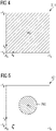
- FIG. 4 illustrates the K-space representation of a preliminary reconstructed image 211 prior to applying the DCO (the reconstructed image 211 corresponds to the reconstructed image 102 of FIG. 1 , but here is specifically denoting the pre-DCO version).
- the K-space representation of the pre-DCO reconstructed image 211 includes K-space values at K-space positions from -Kx to Kx and from -Ky to +Ky, respectively (illustrated by the dashed filling).
- FIG. 5 schematically illustrates a K-space representation of the input image defined by the input dataset 101.
- the K-space representation may be natively included in the respective source data, e.g., for MRI measurements. It would also be possible to perform a Fourier transform to obtain the K-space representation of the input image defined by the input dataset 101, cf. Eq. 1.
- the K-space representation of the input image defined by the input dataset 101 only includes K-space values at K-space positions close to the K-space center (In FIG. 5 , the K-space positions where the respective K-space representation of the reconstructed image 102 and the input image defined by the input dataset 101 include K-space values are also illustrated with a dashed filling).
- a mask 760 that includes all K-space positions for which the K-space representation of the input image includes K-space values is labeled with dashed lines.
- This mask 760 can define the matrix mask of Eq. 2.
- FIG. 6 schematically illustrates the K-space representation of the reconstructed image 212 after applying the DCO (post-DCO reconstructed image).
- the K-space values of the K-space representation of the input image defined by the input dataset 101 have replaced the respective K-space values provided by the reconstruction algorithm, i.e., included in the pre-DCO reconstructed image 211 of FIG. 4 . This corresponds to the DCO according to Eq. 2.
- Other K-space values (for which the input dataset does not include K-space values) in the pre-DCO reconstructed image 211 - i.e., away from the center, outside the mask 760 - are preserved in the post-DCO reconstructed image 212.
- the weighting parameter can be configured to suppress the respective K-space values provided by the reconstruction algorithm 201 if compared to the respective K-space values of the input image.
- the post-DCO reconstructed image 212 includes, at and around the K-space center, K-space values determined only to a certain degree by the reconstruction algorithm 201, but also based on the K-space representation of the input image.
- the degree of suppression is controlled by the value or values of the weighting parameter.
- FIG. 7 illustrates aspects with respect to the weighting parameter 750.
- the weighting parameter 750 (cf. Eq. 4, ⁇ ) - more accurately, its values - can vary as a function of the K-space position.
- the specific configuration of the dependency of the values of the weighting parameter 750 on the K-space position can vary according to different examples.
- the values of the weighting parameter 750 define three regimes 751-753.
- the DCO implements a weighted combination of the K-space values of the pre-DCO reconstructed image 211 and the K-space values of the K-space representation of the input image.
- the K-space representation of the input image does not include any K-space values (cf. FIG. 5 ); and accordingly, the K-space values of the K-space representation of the pre-DCO reconstructed image 211 prevail and are immediately included in the post-DCO reconstructed image 212.
- the shape of the spatial dependency of the values of the weighting parameter as illustrated in FIG. 7 could be manually parametrized or predefined. It would also be possible that the value or values of the weighting parameter are determined using a machine-learned process (as will be explained later in connection with FIG. 9 and FIG. 10 ). In particular, and end-to-end learning of the reconstruction algorithm 2012 together with the value or values of the weighting parameter 750 could be implemented.
- FIG. 8 is a flowchart of a method according to various examples.
- FIG. 8 illustrates an example implementation of the reconstruction algorithm 201.
- the method of FIG. 8 could be executed by the processor 505 of the device 501, upon loading program code from the memory 506.
- the reconstruction algorithm 201 according to the method of FIG. 8 implements a multi-step reconstruction, including multiple iterations or cascades 3071. For instance, an iterative optimization or an unrolled deep neural network could be used to implement the reconstruction algorithm 201 according to the method of FIG. 8 .
- Each iteration or cascade 3071 includes a regularization operation, box 3050; and a DCO at box 3060.
- box 3050 and box 3060 could be based on Knoll, Florian, et al. "Deep learning methods for parallel magnetic resonance image reconstruction.”
- the left term included in the bracket corresponds to the regularization operation of box 3050.
- the DCO applied at box 3060 can be implemented by the FMM according to Eq. 5.
- Eq. 5 corresponds to a modified version of the right-hand term in Knoll et al., Eq. 12 in that the FMM is modified to suppress contributions to the synthesized K-space source data at K-space positions at which the K-space source data has been sampled using the undersampling trajectory. Thereby, the FMM implements the DCO.
- box 3070 it is checked whether a further iteration or cascade 3071 is required; and, in the affirmative, box 3050 and box 3060 are re-executed.
- FIG. 9 is a flowchart of a method according to various examples.
- FIG. 9 illustrates a training phase at box 3505 and an inference phase at box 3510.
- weights of a machine-learned reconstruction algorithm can be set by implementing a respective training process based on a ground truth.
- the training process could be executed by the processor or 505 of the device 501 upon loading program code from the memory 506 and executing the program code.
- the trained reconstruction algorithm can be used for image reconstruction tasks during inference at box 3510 when no ground truth is available.
- FIG. 10 illustrates aspects with respect to training of a machine-learned reconstruction algorithm 201 configured to determine a reconstructed image based on an input dataset (cf. FIG. 1 ).
- ground truth image 903 is available.
- the ground truth image 903 can have desired properties to be achieved by the reconstruction algorithm 201, e.g., a particularly high resolution, suppressed or no artifacts, etc.
- the reconstruction algorithm 201 is initially in a untrained state or has only been partly trained. I.e., weights of, e.g., one or more layers have not been accurately set.
- the purpose of the training process is to accurately set respective parameters of the reconstruction algorithm.
- FIG. 10 also illustrates that a training dataset 901 is available.
- the training dataset 901 is associated with the ground truth image 903.
- the training dataset 901 can define an input image generally corresponding to the ground truth image 903, yet including artifacts or noise or being of lower resolution; i.e., including characteristics that are to suppressed or mitigated by the reconstruction algorithm 201.
- the training dataset 901 can be obtained from measurements or can be inferred from the ground truth image 903 (as illustrated in FIG. 10 ), e.g., by artificially introducing synthesized artifacts or downsampling the resolution, to give just a few options.
- a reference image 902 determined based on the training dataset 901 by using the reconstruction algorithm 201 (in its respective training state). Further, the reference image 902 is obtained after executing the DCO 205.
- the training state of the reconstruction algorithm 201 is changed, e.g., by changing weights of one or more layers, e.g., using backpropagation.
- the DCO can remain fixed during the training process.
- the DCO can be predefined, e.g., according to Eq. 2 or Eq. 4 or Eq. 5.
- the weighting parameter 750 being part of the DCO 205 during the training process.
- the weighting parameter 750 of the DCO 205 and the reconstruction algorithm can be trained end-to-end.
- Such training process is iteratively executed in multiple iterations 999.
- An iterative optimization is thus implementing the training process of the training phase of box 3505.
Landscapes
- Engineering & Computer Science (AREA)
- Physics & Mathematics (AREA)
- Health & Medical Sciences (AREA)
- Theoretical Computer Science (AREA)
- General Health & Medical Sciences (AREA)
- General Physics & Mathematics (AREA)
- Artificial Intelligence (AREA)
- Radiology & Medical Imaging (AREA)
- Nuclear Medicine, Radiotherapy & Molecular Imaging (AREA)
- Computing Systems (AREA)
- Life Sciences & Earth Sciences (AREA)
- Evolutionary Computation (AREA)
- Computational Linguistics (AREA)
- Molecular Biology (AREA)
- Biophysics (AREA)
- General Engineering & Computer Science (AREA)
- Mathematical Physics (AREA)
- Software Systems (AREA)
- Data Mining & Analysis (AREA)
- Biomedical Technology (AREA)
- Computer Vision & Pattern Recognition (AREA)
- Signal Processing (AREA)
- High Energy & Nuclear Physics (AREA)
- Condensed Matter Physics & Semiconductors (AREA)
- Epidemiology (AREA)
- Medical Informatics (AREA)
- Primary Health Care (AREA)
- Public Health (AREA)
- Magnetic Resonance Imaging Apparatus (AREA)
Priority Applications (2)
| Application Number | Priority Date | Filing Date | Title |
|---|---|---|---|
| EP21150346.1A EP4024074A1 (de) | 2021-01-05 | 2021-01-05 | Durchsetzung der datenkonsistenz bei der tiefenlernbildrekonstruktion von magnetresonanzbildern |
| US17/457,948 US12315047B2 (en) | 2021-01-05 | 2021-12-07 | Data-consistency for image reconstruction |
Applications Claiming Priority (1)
| Application Number | Priority Date | Filing Date | Title |
|---|---|---|---|
| EP21150346.1A EP4024074A1 (de) | 2021-01-05 | 2021-01-05 | Durchsetzung der datenkonsistenz bei der tiefenlernbildrekonstruktion von magnetresonanzbildern |
Publications (1)
| Publication Number | Publication Date |
|---|---|
| EP4024074A1 true EP4024074A1 (de) | 2022-07-06 |
Family
ID=74105810
Family Applications (1)
| Application Number | Title | Priority Date | Filing Date |
|---|---|---|---|
| EP21150346.1A Withdrawn EP4024074A1 (de) | 2021-01-05 | 2021-01-05 | Durchsetzung der datenkonsistenz bei der tiefenlernbildrekonstruktion von magnetresonanzbildern |
Country Status (2)
| Country | Link |
|---|---|
| US (1) | US12315047B2 (de) |
| EP (1) | EP4024074A1 (de) |
Cited By (2)
| Publication number | Priority date | Publication date | Assignee | Title |
|---|---|---|---|---|
| EP4375918A1 (de) * | 2022-11-28 | 2024-05-29 | Koninklijke Philips N.V. | Bildverarbeitung |
| EP4614177A1 (de) * | 2024-03-07 | 2025-09-10 | Siemens Healthineers AG | Superauflösung mit nicht-rechteckigen erfassungen |
Families Citing this family (5)
| Publication number | Priority date | Publication date | Assignee | Title |
|---|---|---|---|---|
| US12475614B2 (en) | 2022-03-18 | 2025-11-18 | Siemens Healthineers Ag | Simultaneous multi-slice protocol and deep-learning magnetic resonance imaging reconstruction |
| US20240037815A1 (en) * | 2022-07-26 | 2024-02-01 | Siemens Healthcare Gmbh | Method and apparatus for accelerated acquisition and reconstruction of cine mri using a deep learning based convolutional neural network |
| US12013451B2 (en) | 2022-09-06 | 2024-06-18 | Siemens Healthineers Ag | Noise adaptive data consistency in deep learning image reconstruction via norm ball projection |
| US20250054206A1 (en) * | 2023-08-07 | 2025-02-13 | Siemens Healthineers Ag | Banding artifact reduction for deep learning-based medical image reconstruction |
| US12579716B2 (en) * | 2023-12-20 | 2026-03-17 | Shanghai United Imaging Intelligence Co., Ltd. | MRI reconstruction based on contrastive learning |
Citations (1)
| Publication number | Priority date | Publication date | Assignee | Title |
|---|---|---|---|---|
| US20200065969A1 (en) * | 2018-08-27 | 2020-02-27 | Siemens Healthcare Gmbh | Medical image segmentation from raw data using a deep attention neural network |
Family Cites Families (1)
| Publication number | Priority date | Publication date | Assignee | Title |
|---|---|---|---|---|
| JP2022526718A (ja) * | 2019-03-14 | 2022-05-26 | ハイパーファイン,インコーポレイテッド | 空間周波数データから磁気共鳴画像を生成するための深層学習技術 |
-
2021
- 2021-01-05 EP EP21150346.1A patent/EP4024074A1/de not_active Withdrawn
- 2021-12-07 US US17/457,948 patent/US12315047B2/en active Active
Patent Citations (1)
| Publication number | Priority date | Publication date | Assignee | Title |
|---|---|---|---|---|
| US20200065969A1 (en) * | 2018-08-27 | 2020-02-27 | Siemens Healthcare Gmbh | Medical image segmentation from raw data using a deep attention neural network |
Non-Patent Citations (8)
| Title |
|---|
| AKCAKAYA M. ET AL: "Iterative Compressed Sensing Reconstruction for 3D Non-Cartesian Trajectories without Gridding & Regridding at Every Iteration", INTERNATIONAL SOCIETY FOR MAGNETIC RESONANCE IN MEDICINE, no. 2550, 1 January 2011 (2011-01-01), XP040619288 * |
| ANTUN, V.RENNA, F.POON, C.ADCOCK, B.HANSEN, A. C.: "On instabilities of deep learning in image reconstruction-Does AI come at a cost?", ARXIV:1902.05300, 2019 |
| B. ZHUJ. Z. LIUS. F. CAULEYB. R. ROSENM. S. ROSEN: "Image reconstruction by domain-transform manifold learning", NATURE, vol. 555, no. 7697, March 2018 (2018-03-01), pages 487 |
| HAMMERNIK, KERSTIN ET AL.: "Learning a variational network for reconstruction of accelerated MRI data", MAGNETIC RESONANCE IN MEDICINE, vol. 79, no. 6, 2018, pages 3055 - 3071 |
| ITZIK MALKIEL ET AL: "Conditional WGANs with Adaptive Gradient Balancing for Sparse MRI Reconstruction", ARXIV.ORG, CORNELL UNIVERSITY LIBRARY, 201 OLIN LIBRARY CORNELL UNIVERSITY ITHACA, NY 14853, 3 May 2019 (2019-05-03), XP081271797 * |
| KNOLL, FLORIAN ET AL.: "Deep learning methods for parallel magnetic resonance image reconstruction", ARXIV:1904.01112, 2019 |
| MALKIEL I. ET AL: "Densely Connected Iterative Network for Sparse MRI Reconstruction", INTERNATIONAL SOCIETY FOR MAGNETIC RESONANCE IN MEDICINE, ISMRM, 2030 ADDISON STREET, 7TH FLOOR, BERKELEY, CA 94704 USA, no. 3363, 1 June 2018 (2018-06-01), XP040702571 * |
| YIP E. ET AL: "Prior Data Assisted Compressed Sensing - A Novel Strategy for Real Time Dynamic MRI", INTERNATIONAL SOCIETY FOR MAGNETIC RESONANCE IN MEDICINE, ISMRM, 2030 ADDISON STREET, 7TH FLOOR, BERKELEY, CA 94704 USA, no. 4372, 28 April 2014 (2014-04-28), XP040671145 * |
Cited By (2)
| Publication number | Priority date | Publication date | Assignee | Title |
|---|---|---|---|---|
| EP4375918A1 (de) * | 2022-11-28 | 2024-05-29 | Koninklijke Philips N.V. | Bildverarbeitung |
| EP4614177A1 (de) * | 2024-03-07 | 2025-09-10 | Siemens Healthineers AG | Superauflösung mit nicht-rechteckigen erfassungen |
Also Published As
| Publication number | Publication date |
|---|---|
| US20220215600A1 (en) | 2022-07-07 |
| US12315047B2 (en) | 2025-05-27 |
Similar Documents
| Publication | Publication Date | Title |
|---|---|---|
| US12315047B2 (en) | Data-consistency for image reconstruction | |
| US20230342886A1 (en) | Method and system for low-field mri denoising with a deep complex-valued convolutional neural network | |
| US12039638B2 (en) | Magnetic resonance imaging reconstruction using machine learning | |
| RU2568929C1 (ru) | Способ и система для быстрой реконструкции изображения мрт из недосемплированных данных | |
| US20200341094A1 (en) | Multi-contrast mri image reconstruction using machine learning | |
| Ye et al. | Computational acceleration for MR image reconstruction in partially parallel imaging | |
| US11941732B2 (en) | Multi-slice MRI data processing using deep learning techniques | |
| Baselice et al. | Bayesian MRI denoising in complex domain | |
| KR20230069501A (ko) | 스코어 기반의 확산 모델을 이용한 자기공명영상 복원 방법 및 그 장치 | |
| CN112509120B (zh) | 用于重建图像的系统和方法 | |
| Sun et al. | Region-of-interest undersampled MRI reconstruction: a deep convolutional neural network approach | |
| US12315045B2 (en) | Task-specific training of reconstruction neural network algorithm for magnetic resonance imaging reconstruction | |
| KR102769810B1 (ko) | K-space 도메인에 인공신경망을 적용한 자기 공명 영상 처리 장치 및 그 방법 | |
| CN107705261A (zh) | 一种图像重建方法和装置 | |
| Ding et al. | Mri reconstruction by completing under-sampled k-space data with learnable fourier interpolation | |
| Yeganli et al. | Noise removal from MR images via iterative regularization based on higher-order singular value decomposition | |
| US12175667B2 (en) | On-site training of a machine-learning algorithm for generating synthetic imaging data | |
| Dhengre et al. | K sparse autoencoder-based accelerated reconstruction of magnetic resonance imaging | |
| Schauman et al. | Deep learning initialized compressed sensing (Deli-CS) in volumetric spatio-temporal subspace reconstruction | |
| Chen et al. | Data-consistency in latent space and online update strategy to guide GAN for fast MRI reconstruction | |
| Liu et al. | Highly undersampled mri reconstruction via a single posterior sampling of diffusion models | |
| US12482149B2 (en) | Under-sampled magnetic resonance image reconstruction of an anatomical structure based on a machine-learned image reconstruction model | |
| CN116977458A (zh) | 一种产生多通道空间支持图的方法与系统 | |
| Han et al. | Inhomogeneity correction in magnetic resonance images using deep image priors | |
| CN113240078B (zh) | 基于深度学习网络的磁共振r2*参数量化方法、介质及设备 |
Legal Events
| Date | Code | Title | Description |
|---|---|---|---|
| PUAI | Public reference made under article 153(3) epc to a published international application that has entered the european phase |
Free format text: ORIGINAL CODE: 0009012 |
|
| STAA | Information on the status of an ep patent application or granted ep patent |
Free format text: STATUS: THE APPLICATION HAS BEEN PUBLISHED |
|
| AK | Designated contracting states |
Kind code of ref document: A1 Designated state(s): AL AT BE BG CH CY CZ DE DK EE ES FI FR GB GR HR HU IE IS IT LI LT LU LV MC MK MT NL NO PL PT RO RS SE SI SK SM TR |
|
| STAA | Information on the status of an ep patent application or granted ep patent |
Free format text: STATUS: REQUEST FOR EXAMINATION WAS MADE |
|
| 17P | Request for examination filed |
Effective date: 20221229 |
|
| RBV | Designated contracting states (corrected) |
Designated state(s): AL AT BE BG CH CY CZ DE DK EE ES FI FR GB GR HR HU IE IS IT LI LT LU LV MC MK MT NL NO PL PT RO RS SE SI SK SM TR |
|
| RAP1 | Party data changed (applicant data changed or rights of an application transferred) |
Owner name: SIEMENS HEALTHINEERS AG |
|
| STAA | Information on the status of an ep patent application or granted ep patent |
Free format text: STATUS: EXAMINATION IS IN PROGRESS |
|
| 17Q | First examination report despatched |
Effective date: 20241011 |
|
| STAA | Information on the status of an ep patent application or granted ep patent |
Free format text: STATUS: THE APPLICATION IS DEEMED TO BE WITHDRAWN |
|
| 18D | Application deemed to be withdrawn |
Effective date: 20250212 |