EP4024101B1 - Glasfaserfusionsspleisser - Google Patents
Glasfaserfusionsspleisser Download PDFInfo
- Publication number
- EP4024101B1 EP4024101B1 EP19945932.2A EP19945932A EP4024101B1 EP 4024101 B1 EP4024101 B1 EP 4024101B1 EP 19945932 A EP19945932 A EP 19945932A EP 4024101 B1 EP4024101 B1 EP 4024101B1
- Authority
- EP
- European Patent Office
- Prior art keywords
- optical fiber
- clamping
- cutting
- driving component
- moving
- Prior art date
- Legal status (The legal status is an assumption and is not a legal conclusion. Google has not performed a legal analysis and makes no representation as to the accuracy of the status listed.)
- Active
Links
Images



Classifications
-
- G—PHYSICS
- G02—OPTICS
- G02B—OPTICAL ELEMENTS, SYSTEMS OR APPARATUS
- G02B6/00—Light guides; Structural details of arrangements comprising light guides and other optical elements, e.g. couplings
- G02B6/24—Coupling light guides
- G02B6/25—Preparing the ends of light guides for coupling, e.g. cutting
-
- G—PHYSICS
- G02—OPTICS
- G02B—OPTICAL ELEMENTS, SYSTEMS OR APPARATUS
- G02B6/00—Light guides; Structural details of arrangements comprising light guides and other optical elements, e.g. couplings
- G02B6/24—Coupling light guides
- G02B6/255—Splicing of light guides, e.g. by fusion or bonding
-
- G—PHYSICS
- G02—OPTICS
- G02B—OPTICAL ELEMENTS, SYSTEMS OR APPARATUS
- G02B6/00—Light guides; Structural details of arrangements comprising light guides and other optical elements, e.g. couplings
- G02B6/24—Coupling light guides
- G02B6/255—Splicing of light guides, e.g. by fusion or bonding
- G02B6/2551—Splicing of light guides, e.g. by fusion or bonding using thermal methods, e.g. fusion welding by arc discharge, laser beam, plasma torch
-
- G—PHYSICS
- G02—OPTICS
- G02B—OPTICAL ELEMENTS, SYSTEMS OR APPARATUS
- G02B6/00—Light guides; Structural details of arrangements comprising light guides and other optical elements, e.g. couplings
- G02B6/24—Coupling light guides
- G02B6/255—Splicing of light guides, e.g. by fusion or bonding
- G02B6/2553—Splicing machines, e.g. optical fibre fusion splicer
Definitions
- the present invention relates to an optical fiber fusion splicer.
- Existing portable fiber fusion splicers can fuse two stripped and cut optical fibers.
- the optical fiber fusion splicers disclosed in U.S. Patent No. US 2017/242193 A1 or Chinese Patent No. CN 103529516 B fuse two stripped and cut optical fibers.
- cutting fiber ends typically requires the use of a separate tool. This mode of operation is less efficient when large batches of fibers need to be fused.
- VYTRAN LLC in the United States has proposed a systematic solution, which uses a cabinet with a station on the upper surface of the cabinet; a plurality of modules with different processing functions inside the cabinet can successively move to the station position and extend out of the station; and clamping parts for optical fibers are provided on both sides of the station, the clamping parts clamp the optical fibers to reciprocate and the corresponding modules extend out of the station successively to process the optical fibers.
- This system is bulky and not suitable for on-site transferring.
- Chinese utility model patent CN 202563119 U also discloses a cutting and positioning type optical fiber fusion splicer, which can cut an optical fiber and then complete the fusion of the optical fiber by discharging and pushing the end face.
- the utility model eliminates the need for a separate cutting knife and simplifies the fusion welding structure.
- the optical fiber cutting structure of the optical fiber fusion splicer of the utility model structure does not form a good cutting effect, thereby reducing the quality of the fused optical fiber
- US 5999682 A concerns a tool for carrying out all the operations for end-to end joining a fiber either to another fiber or to an optical connector member.
- JP 562223708 A reduces the horizontal carriage of an optical fiber core as less as possible by successively driving a carrying board to be optionally moved in the axial direction of the optical fiber core and a coat removing/fusion splicing process mechanism to be optionally moved in the direction rectangular to said moving direction.
- CN 207281328 U discloses a weld holder to be used for optic fibre welded.
- JP H05224024 A provides a scalping device for small-sized coated optical fibers which does not occupy a space in a direction where the coated optical fibers to be connected are supplied.
- an object of the present invention to provide an optical fiber fusion splicer capable of integrating the functions of cutting and fusion splicing, having a compact structure and a good fusion splicing effect.
- An optical fiber fusion splicer comprises a working platform and a fusion splicing part provided on the working platform, wherein the fusion splicing part can splice optical fibers, wherein the optical fiber fusion splicer further comprises:
- the second clamping part of each of the cutting parts comprises a second fixed part and a second moving part, wherein each of the cutting parts is provided with a driving part, which drives the cutting blade to move towards or away from the second fixed part; the cutting blade is connected to the second moving part via an elastic part; when the elastic part is in an extended state, the second moving part is closer to the position where the optical fiber is located than the cutting blade; and when the elastic part is compressed and contracted as the second moving part is in contact with the second fixed part, the cutting blade can continue to move towards the position where the optical fiber is located so as to contact the optical fiber.
- the direction of movement of the cutting part is perpendicular to the length direction of the optical fiber.
- the first clamping part moves in the direction away from the splicing part, so that the optical fiber stretches and a tensile stress is applied on the optical fiber; and then the cutting blade moves to the position where the optical fiber is located for cutting.
- the cutting blade is in the shape of a disc, which is rotatable about the disc axis when driven by a motor.
- the cutting part is mounted on a second machine frame which is driven towards or away from the position of the optical fiber by a second driving component; and the second driving component has a greater feed rate than that of the driving component.
- the motor drives and rotates the cutting blade via a belt pulley.
- the driving component and the second driving component comprises a drive gear and a gear rack cooperating therewith.
- the first clamping part comprises:
- the clamping element can move towards or away from the fusion splicing part with respect to the moving support; and an elastic element is provided between the clamping element and the moving support.
- the clamping element can move towards or away from the fusion splicing part with respect to the moving support; a fourth driving component for driving the clamping element to move is also fixed to the moving support; and the fourth driving component has a smaller feed rate than that of the third driving component.
- the clamping element is mounted on the moving support by means of a sliding block; the clamping element is hinged on the sliding block; a fifth driving component and a cam driven by the fifth driving component are further mounted on the sliding block; the cam is in contact with a lower surface of the clamping element; and a return spring is further mounted between the clamping element and the sliding block.
- the clamping element is mounted on the moving support by the sliding block; an elastic element is provided between the sliding block and the moving support; a fourth driving component for driving the movement of the sliding block is further fixed on the moving support; the fourth driving component has a smaller feeding amount than that of the third driving component; and the fourth driving component can be in contact with or separated from the sliding block and is used for driving the movement of the sliding block when the fourth driving component is in contact with the sliding block.
- the fourth driving component comprises a motor and a lead screw transmission mechanism driven by the motor; and a free end of the lead screw transmission mechanism can come into contact with the sliding block.
- an automatic fiber stripping device is further mounted on the working platform.
- the driving component for the first clamping part, the cutting part and the fusion splicing part are a stepper motor; a control end of the stepper motor is connected to a microprocessor which performs the following steps:
- a second U-shaped frame is provided on the second fixed part; a first U-shaped frame is provided on the second moving part; the first U-shaped frame and the second U-shaped frame are arranged such that the clamping surface of a second moving component can pass through the second U-shaped frame and the first U-shaped frame can pass through the clamping surface of the second fixed part when the second moving component moves.
- optical fiber fusion splicer can achieve the functions of cutting optical fibers and fusion splicing, and has a compact structure.
- the working platform can be made in the size of about 40CM X 60CM, which is easy to be carried on the spot.
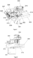
- an optical fiber fusion splicer includes a work platform 1 and a fusion splicing part 7 provided on the working platform 1.
- the fusion splicing part 7 may take the same structure as existing fusion splicers. It is capable of electrical discharge cleaning the surface of the optical fibers, then fine-tuning the position of the optical fibers, and finally electrical discharge splicing the optical fibers together.
- a first clamping part 3 is provided on the left side of the fusion splicing part 7; a first clamping part 4 is provided on the right side of the fusion splicing part 7; and the first clamping part 3 and the first clamping part 4 are symmetrically arranged on the left and right with respect to the fusion splicing part 7 and have the same structure.
- the first clamping parts 3 and 4 can clamp the optical fibers and move along the length direction of the optical fibers.
- the optical fiber fusion splicer of this embodiment also has a control processor and a human-computer interaction device 2 for controlling the movement of the components to complete the fiber cutting and splicing process.
- a cutting part 5 is provided on the left side of the fusion splicing part 7; a cutting part 6 is provided on the right side of the fusion splicing part 7; and the cutting part 5 and the cutting part 6 are symmetrically provided with respect to the fusion splicing part 7 and have the same structure.
- the cutting part 5 is located between the first clamping part 3 and the fusion splicing part 7; and the cutting part 6 is located between the first clamping part 4 and the fusion splicing part 7. Since the structures of the cutting parts 5, 6 are the same or similar, only the structure of the cutting part 5 is described in this embodiment; and the cutting part 6 may has the same or similar structure as that of the cutting part 5.
- the cutting part 5 has a cutting blade 501 and a second clamping part, which is located between the cutting blade 501 and the fusion splicing part 7, as shown in Fig. 2 .
- the second clamping part includes a second fixed part 503 and a second moving part 502, wherein the second moving part 502 can move relative to the second fixed part 503 to clamp or loosen the optical fibers.
- the cutting parts 5, 6 can be moved out of position between the first clamping parts 3, 4 and the fusion splicing part 7.
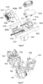
- the first clamping part 3, as shown in Figs. 3 and 4 includes a machine frame 303, which is mounted on the working platform 1.
- a through hole is formed on the bottom surface of the machine frame 303; a motor 301 is mounted below the machine frame 303; the shaft of the motor 301 passes through the through hole on the bottom surface of the machine frame 303; and a gear 314 is mounted on the shaft of the motor 301, the gear 314 being located above the upper surface of the machine frame 303.
- a gear rack 315 cooperating with the gear 314 is arranged along the length direction of the optical fiber, and is driven to reciprocate by the gear 314.
- a support 306 is fixed to the gear rack 315 (in some embodiments, the gear rack 315 and a first portion 306a of the support may be integrally formed; and a second portion 306b of the support may be a circuit board that may be used to mount an interface or part of a control circuit).
- the support 306 is provided with a boss 316 having a through hole along the length of the optical fiber.
- a sliding block 305 is also provided on the machine frame 303, which can slide on the machine frame 303; and a fiber clamping part 304 is mounted on the sliding block 305.
- a rod 311 is also provided on the sliding block 305 on the side of the sliding block 305 remote from the fusion splicing part 7 and extends in the length direction of the optical fiber in the direction away from the fusion splicing part 7.
- the rod 311 passes through a through hole in the boss 316; and a spring or other elastic member (e. g. an elastic washer, a snap ring, etc.) is provided between the rod 311 and the boss.
- the support 306 includes a first portion 306a and a second portion 306b, which are assembled together by screws to form the support 306.
- a vertical mounting plate 317 is also provided on the support 306 and mounted with a big gear 308 and a pinion 307 engaged therewith, the big gear 308 being driven by a stepper motor 309.
- the pinion 307 drives a lead screw 310, which can contact an end of the rod 311; when the rod 311 needs to be finely adjusted, the lead screw 310 pushes the rod 311 forward for fine adjustment; and when the lead screw 310 retreats, the rod 311 keeps in contact with the lead screw 310 for fine adjustment with the drive by the elastic element.
- the clamping state can be sensed by a sensor, and the control system can be notified; the driving motor 301 drives the gear 314 to rotate, and drives the gear rack 315 to move to the left away from the fusion splicing part 7; the gear rack 315 drives the support 306 to move to the left; and the boss on the support 306 pulls the rod 311 to the left via the spring.
- the length of the optical fibers between the two is constant; and during the retraction of the support 306, the spring on the rod 311 is compressed, thereby forming a certain stress on the optical fibers and facilitating the cutting to form a good cutting port.
- the first clamping part further comprises a mounting platform 318 mounted on the sliding block 305, the mounting platform 318 being hinged to the sliding block 305.
- the clamping part 304 is mounted on the mounting platform 318 and, together with the mounting platform 318, constitutes a clamping element.
- a motor 302 is also mounted on the sliding block 305; the shaft of the motor 302 drives a cam 312 to rotate; the edge of the cam 312 is in contact with the bottom surface of the mounting platform 318; and a return spring 313 is mounted between the mounting platform 318 and the sliding block 305.
- the cam 312 cooperates with the spring 313 to control the tilt angle of the mounting platform 318 so as to adjust the angle of the fiber in the clamping part 304 for placing the fiber end into a V-groove in the fusion splicing part 7.
- the cutting part 5 comprises a machine frame 509 for being mounted on the working platform 1.
- a motor 506 is mounted on the bottom of the machine frame 509, and the motor shaft rotates the gear 507.
- the gear rack 505 meshes with the gear 507 and is arranged in a direction perpendicular to the length direction of the optical fiber.
- a second machine frame 511 is fixed to the gear rack 505, and a motor 510 is mounted on the second machine frame 511.
- the shaft of the motor 510 is provided with a gear 512 which meshes with a gear rack 513 arranged in the same direction as the rack 505.
- a third machine frame 517 is fixed to the gear rack 513, and the third machine frame 517 can reciprocate with the gear rack 513.
- a motor 516 is mounted on the third machine frame 517, and the motor 516 is used for driving the cutting blade 501 to rotate; a through hole is further provided on the third machine frame 517; one end of a rod 514 passes through the through hole, and the other end of the rod 514 is fixedly connected to the second moving part 502; the second moving part 502 is mounted on the second machine frame 511 via the sliding block; and a spring 515 or other elastic element is provided between the second moving part 502 and the third machine frame 517.
- a second fixed part 503 cooperating with the second moving part 502 is further provided on the second machine frame 511; and the cooperation of the second fixed part 503 and the second moving part 502 serves to clamp the optical fibers.
- the cutting process is as follows: the control system firstly detects that the position of the second machine frame is at an initial position (the second machine frame 511 is located at one side close to the second fixed part 503; and if the second machine frame 511 is not at the initial position, the second machine frame is driven to the initial position by the motor 506), and places the optical fiber into the first clamping part; after the optical fiber is placed into the first clamping part 3, the clamping state is sensed by the sensor; the controller instructs the motor 510 to rotate, and the third machine frame 517 is pushed forward (towards the direction in which the optical fibers are located) via the gear rack 513; the cutting blade 501 mounted on the third machine frame 517 and the second moving part 502 driven by a spring 515 or other elastic elements are provided between the third machine frame 517 to move forward at the same time; when the second moving part 502 contacts with the second fixed part 503 to clamp the optical fibers, the second moving part 502 stops moving forward, and the third machine frame 517 continues to move forward
- the motor 510 and the motor 506 rotate in the reverse direction, so that each component is reset; the spring 515 is restored to the original length; and then the second moving part 502 is separated from the second fixed part 503.
- the motor 506 drives the gear rack 505 via the gear 507 to fully withdraw the second machine frame 511 from the cutting position, leaving it to the first clamping part 3, which facilitates the feeding of the optical fibers into the fusion splicing part 7.
- the fusion splicing part 7 is the same as or similar to the fusion splicer of the prior art, and has a discharge electrode, a fine adjustment device, etc.
- the fusion splicing part 7 comprises a motor 701 for driving the opening and closing of a cover 707 by means of a transmission member; a pair of pressing plates 706 are mounted on the cover; and a pair of V-grooves 704 for placing the optical fibers corresponds to the pressing plates 706.
- the V-groove 704 is placed on a fine adjustment base 703 that can perform fine adjustment on the position of the V-groove 704 to ensure alignment of the fibers on both sides.
- a camera 702 and a camera 705 are also provided beside the V-groove 704 for observing the position of the optical fiber.
- the cover 707 is closed; and the pressing plate 706 presses the optical fibers into the V-groove; and after fine adjustment of the position of the optical fibers, electric discharge fusion splicing can be performed by an electrode (not shown).
- first clamping part and the cutting part are arranged symmetrically with respect to the fusion splicing part 7, or the structure and operation principle of the first clamping part and the cutting part on both sides are the same or similar, only the structure and operation principle of one side are described, and the structure and operation principle of the component on the other side are the same or similar to those described above.
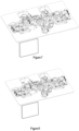
- the coating layer on the both ends of the optical fiber to be spliced is stripped by a length, wiped with alcohol, and then respectively put into the first clamping parts 3 and 4 of the optical fiber fusion splicer, as shown in Fig. 7 .
- the first clamping parts on both sides are snapped together; and after the sensor receives the snapping signal, the cutting parts 5 and 6 are driven to move, and the second clamping part clamps the optical fibers, as shown in Fig. 8 .
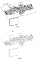
- the motor drives the first clamping part to retreat; the rod 311 compresses the spring; a gap occurs between the rod 311 and the lead screw 310; and the first clamping part and the second clamping part cooperate to tension the optical fibers, and the spring provides tensile stress, as shown in Fig. 9 .
- the cutting blade 501 in the cutting part continues to approach the fibers as it rotates about its own axis, thereby cutting the fibers and making a good cut, as shown in Fig. 10 .
- the cutting part is withdrawn from a position between the first clamping part and the fusion splicing part, as shown in Fig. 11 .
- the first clamping part is fed towards the fusion splicing part, and the optical fibers will enter above the fusion splicing area, as shown in Fig. 12 .
- the first clamping part can adjust the included angle between the optical fiber and the horizontal plane by means of the cam transmission mechanism in the above-mentioned embodiment (or other transmission mechanism known to a person skilled in the art, such as a stepper motor cooperating with a gear to adjust the rotation angle of the hinge shaft, or otherwise controlling the vertical height of the first clamping part), so that the optical fiber is placed in the V-groove, as shown in Fig. 13 .
- the cover of the fusion splicing part is pressed down, the fine adjustment base performs fine adjustment alignment on the optical fibers, and the electrode is discharged to complete the fusion splicing part of the optical fibers, as shown in Fig. 14 .
- the above-mentioned position control can be realized by the cooperation of sensors and programmable controllers. A person skilled in the art would have been able to realize the arrangement of these sensors and the control relationship of the programmable controllers on the basis of the disclosure of the present invention.
- an automatic fiber stripping device may be further mounted on the working platform.
- the automatic fiber stripping device can be any existing automatic fiber stripping device, such as disclosed in Chinese patent application for invention (publication number CN101943769A ) or Chinese utility model CN207366782U , or a device well known to those skilled in the art.
- a defibering component is further provided on the second moving part 502; and a second U-shaped frame 534 is fixedly connected to the second fixed part 503, as shown in Fig. 15 .
- the defibering part moving with the second moving part 502 includes a rod 531 extending towards the second fixed part 503 and a first U-shaped frame 532 extending from an end of the rod 531; and the first U-shaped frame 532 surrounds outside of the second fixed part 503.
- the rod 531 and the first U-shaped frame 532 are arranged such that, when the second moving part 502 contacts the second fixed part 503, the first U-shaped frame 532 is located behind the clamping surface of the second fixed part 503 (in a direction away from the second moving part 502); and when the second moving part 502 moves away from the second fixed part 503, the first U-shaped frame 532 moves along with the second moving part 502 and gradually moves to the front of the clamping surface of the second fixed part 503.
- the space enclosed by the second U-shaped frame 534 is slightly larger than that of the second moving part 502; and the second moving part 502 passes through the second U-shaped frame 534 during forward or backward movement.
- the movement of the first U-shaped frame 532 or the second U-shaped frame 534 relative to the second fixed part 503 or the second moving part 502 serves to push the optical fibers away from the clamping surface and down into a waste fiber box 535 below.
Landscapes
- Physics & Mathematics (AREA)
- Engineering & Computer Science (AREA)
- Plasma & Fusion (AREA)
- General Physics & Mathematics (AREA)
- Optics & Photonics (AREA)
- Mechanical Coupling Of Light Guides (AREA)
Claims (16)
- Glasfaserfusionsspleißer umfassend ein Fusionsspleißteil (7), wobei das Fusionsspleißteil (7) Glasfasern spleißen kann, wobei der Glasfaserfusionsspleißer ferner umfasst:ein erstes Klemmteil (3, 4), das jeweils auf beiden Seiten des Fusionsspleißteils (7) angeordnet ist, wobei die ersten Klemmteile (3, 4) Glasfasern einklemmen und sich in der Längsrichtung der Glasfasern bewegen können;ein Schneidteil (5, 6), das jeweils auf beiden Seiten des Fusionsspleißteils (7) angeordnet ist, wobei die Schneidteile (5, 6) zwischen den ersten Klemmteilen (3, 4) und dem Fusionsspleißteil (7) angeordnet sind und mit Schneidklingen (501), die zum Schneiden von Glasfasern geeignet sind, und zweiten Klemmteilen versehen sind;die zweiten Klemmteile zwischen den Schneidklingen (501) und dem Fusionsspleißteil (7) angeordnet sind;wobei die Schneidteile (5, 6) beweglich sind, so dass die Schneidteile (5, 6) sich aus Positionen zwischen den ersten Klemmteilen (3, 4) und dem Fusionsspleißteil (7) zurückziehen, dadurch gekennzeichnet, dass der Glasfaserfusionspleißer eine Arbeitsplattform (1) und das auf der Arbeitsplattform (1) angeordnete Fusionsspleißteil (7) umfasst, und das zweite Klemmteil jedes der Schneidteile (5, 6) ein zweites festes Teil (503) und ein zweites bewegliches Teil (502) umfasst, wobei jedes der Schneidteile (5, 6) mit einem Antriebsteil versehen ist, das die Schneidklinge (501) antreibt, um sich zu dem zweiten festen Teil (503) hin oder von ihm weg zu bewegen; wobei die Schneidklinge (501) mit dem zweiten beweglichen Teil über ein elastisches Teil verbunden ist; wenn sich das elastische Teil in einem ausgefahrenen Zustand befindet, ist das zweite bewegliche Teil (502) näher an der Position, an der sich die Glasfaser befindet, als die Schneidklinge (501); und wenn das elastische Teil zusammengedrückt und zusammengezogen wird, während das zweite bewegliche Teil (502) in Kontakt mit dem zweiten festen Teil (503) ist, kann sich die Schneidklinge (501) weiter zu der Position bewegen, an der sich die Glasfaser befindet, um die Glasfaser zu berühren.
- Glasfaserfusionsspleißer nach Anspruch 1, dadurch gekennzeichnet, dass die Bewegungsrichtung des Schneidteils (5, 6) senkrecht zur Längsrichtung der Glasfaser verläuft.
- Glasfaserfusionsspleißer nach Anspruch 1, dadurch gekennzeichnet, dass, wenn das zweite Klemmteil die Glasfaser einklemmt, sich das erste Klemmteil (3, 4) in die Richtung weg von dem Spleißteil bewegt, so dass sich die Glasfaser dehnt und eine Zugspannung auf die Glasfaser ausgeübt wird; und dann bewegt sich die Schneidklinge (501) zu der Position, an der die Glasfaser zum Schneiden angeordnet ist.
- Glasfaserfusionsspleißer nach Anspruch 1, dadurch gekennzeichnet, dass die Schneidklinge (501) die Form einer Scheibe hat, die um die Scheibenachse drehbar ist, wenn sie von einem Motor (301) angetrieben wird.
- Glasfaserfusionsspleißer nach Anspruch 1, dadurch gekennzeichnet, dass das Schneidteil (5, 6) auf einem zweiten Maschinenrahmen (511) angeordnet ist, der durch eine zweite Antriebskomponente zur Position der Glasfaser hin oder von ihr weg angetrieben wird; und die zweite Antriebskomponente einen größeren Vorschub als die Antriebskomponente aufweist.
- Glasfaserfusionsspleißer nach Anspruch 4, dadurch gekennzeichnet, dass der Motor (301) das Schneidmesser (501) über eine Riemenscheibe antreibt und dreht.
- Glasfaserfusionsspleißer nach Anspruch 5, dadurch gekennzeichnet, dass die Antriebskomponente und die zweite Antriebskomponente ein Antriebsrad und eine damit zusammenwirkende Zahnstange (315) umfasst.
- Glasfaserfusionsspleißer nach Anspruch 1, dadurch gekennzeichnet, dass das erste Klemmteil (3, 4) umfassend ein Klemmelement zum Klemmen von Glasfasern;eine bewegliche Halterung, an der das Klemmelement angeordnet ist, wobei sich die bewegliche Halterung (306) zu dem Fusionsspleißteil (7) hin oder von ihm weg bewegen kann; undeine dritte Antriebskomponente, um den beweglichen Träger (306) zu bewegen.
- Glasfaserfusionsspleißer nach Anspruch 8, dadurch gekennzeichnet, dass sich das Klemmelement in Bezug zu der beweglichen Halterung (306) auf das Fusionsspleißteil (7) zu oder von diesem weg bewegen kann; und ein elastisches Element zwischen dem Klemmelement und der beweglichen Halterung (306) angeordnet ist.
- Glasfaserfusionsspleißer nach Anspruch 8, dadurch gekennzeichnet, dass sich das Klemmelement in Bezug zu der beweglichen Halterung (306) auf das Fusionsspleißteil (7) zu oder von ihm weg bewegen kann; eine vierte Antriebskomponente zum Bewegen des Klemmelements ebenfalls an der beweglichen Halterung befestigt ist; und die vierte Antriebskomponente einen geringeren Vorschub als die dritte Antriebskomponente aufweist.
- Glasfaserfusionsspleißer nach Anspruch 8, dadurch gekennzeichnet, dass das Klemmelement mittels eines Gleitblocks an der beweglichen Halterung angebracht ist; das Klemmelement an dem Gleitblock gelenkig angeordnet ist; eine fünfte Antriebskomponente und eine von der fünften Antriebskomponente angetriebener Nocken (312) ferner an dem Gleitblock angeordnet sind; der Nocken (312) in Kontakt mit einer unteren Fläche des Klemmelements steht; und eine Rückholfeder ferner zwischen dem Klemmelement und dem Gleitblock angeordnet ist.
- Glasfaserfusionsspleißer nach Anspruch 8, dadurch gekennzeichnet, dass das Klemmelement durch den Gleitblock an der beweglichen Halterung (306) angeordnet ist; ein elastisches Element zwischen dem Gleitblock und der beweglichen Halterung (306) angeordnet ist; eine vierte Antriebskomponente zum Antreiben der Bewegung des Gleitblocks ferner an der beweglichen Halterung (306) befestigt ist; die vierte Antriebskomponente hat einen geringeren Vorschub als die dritte Antriebskomponente; und die vierte Antriebskomponente kann in Kontakt mit dem Gleitstein sein oder von diesem getrennt sein und wird zum Antrieb der Bewegung des Gleitsteins verwendet, wenn die vierte Antriebskomponente in Kontakt mit dem Gleitstein ist.
- Glasfaserfusionsspleißer nach Anspruch 12, dadurch gekennzeichnet, dass die vierte Antriebskomponente einen Motor (301) und einen durch den Motor (301) angetriebenen Leitspindelübertragungsmechanismus umfasst; und ein freies Ende des Leitspindelübertragungsmechanismus mit dem Gleitblock in Kontakt kommen kann.
- Glasfaserfusionsspleißer nach Anspruch 1, dadurch gekennzeichnet, dass auf der Arbeitsplattform ferner eine automatische Faserabisoliervorrichtung angeordnet ist.
- Glasfaserfusionsspleißer nach Anspruch 1, dadurch gekennzeichnet, dass die Antriebskomponente für das erste Klemmteil, das Schneidteil und das Fusionsspleißteil (7) ein Schrittmotor (309) ist; ein Steuerende des Schrittmotors (309) ist mit einem Mikroprozessor verbunden, der geeignet ist, die folgenden Schritte durchzuführen:Einklemmen der Glasfasern durch das zweite Klemmteil;Bewegen des ersten Klemmteils um eine vorbestimmte Strecke in eine Richtungwegvon dem Fusionsspleißteil (7);Zuführen der Schneidklinge (501) zum Schneiden der Glasfasern;Herausbewegen des Schneidteils (5, 6) zwischen dem ersten Klemmteil (3, 4) und dem Fusionsspleißteil (7);Zuführung durch das erste Klemmteil (3, 4), um die geschnittenen Glasfasern in das Fusionsspleißteil (7) zu legen; undAusführen der Positionseinstellung der Glasfasern und des Schmelzspleißens durch das Fusionsspleißteil (7).
- Glasfaserfusionsspleißer nach Anspruch 1, dadurch gekennzeichnet, dass ein zweiter U-förmiger Rahmen an dem zweiten feststehenden Teilangeordnet ist; ein erster U-förmiger Rahmen an dem zweiten beweglichen Teil vorgesehen ist; der erste U-förmige Rahmen und der zweite U-förmige Rahmen so angeordnet sind, dass die Klemmfläche einer zweiten beweglichen Komponente durch den zweiten U-förmigen Rahmen hindurchgehen kann und der erste U-förmige Rahmen durch die Klemmfläche des zweiten feststehenden Teils hindurchgehen kann, wenn sich die zweite bewegliche Komponente bewegt.
Applications Claiming Priority (1)
| Application Number | Priority Date | Filing Date | Title |
|---|---|---|---|
| PCT/CN2019/105954 WO2021051234A1 (zh) | 2019-09-16 | 2019-09-16 | 光纤熔接机 |
Publications (4)
| Publication Number | Publication Date |
|---|---|
| EP4024101A1 EP4024101A1 (de) | 2022-07-06 |
| EP4024101A4 EP4024101A4 (de) | 2022-10-05 |
| EP4024101C0 EP4024101C0 (de) | 2024-08-14 |
| EP4024101B1 true EP4024101B1 (de) | 2024-08-14 |
Family
ID=71682219
Family Applications (1)
| Application Number | Title | Priority Date | Filing Date |
|---|---|---|---|
| EP19945932.2A Active EP4024101B1 (de) | 2019-09-16 | 2019-09-16 | Glasfaserfusionsspleisser |
Country Status (3)
| Country | Link |
|---|---|
| EP (1) | EP4024101B1 (de) |
| CN (1) | CN111465880B (de) |
| WO (1) | WO2021051234A1 (de) |
Families Citing this family (13)
| Publication number | Priority date | Publication date | Assignee | Title |
|---|---|---|---|---|
| CN112684543B (zh) * | 2021-01-08 | 2023-02-07 | 周婵 | 光纤接头切割装置 |
| CN113770939A (zh) * | 2021-09-01 | 2021-12-10 | 苏州天孚光通信股份有限公司 | 一种光纤镀膜装置及其使用方法 |
| CN114783766B (zh) * | 2022-04-26 | 2024-01-05 | 东莞市泰元达机械设备有限公司 | 一种绕线机 |
| CN116643357B (zh) * | 2023-06-09 | 2024-01-26 | 江苏西贝电子网络有限公司 | 一种便于光缆固定的光缆熔接操作装置及其使用方法 |
| CN116953851A (zh) * | 2023-08-22 | 2023-10-27 | 桂林电子科技大学 | 一种光纤切割熔接装置及该装置的使用方法 |
| CN117031632B (zh) * | 2023-10-08 | 2023-12-22 | 四川灼识科技股份有限公司 | 一种光纤加工设备及自动打纤方法 |
| CN117214998A (zh) * | 2023-11-08 | 2023-12-12 | 维特瑞交通科技有限公司 | 一种高频振动式光纤熔融焊接装置 |
| CN117741867B (zh) * | 2023-12-28 | 2024-06-07 | 江苏斯特利通信科技有限公司 | 一种核电站光缆连接用熔接装置 |
| CN118604949B (zh) * | 2024-05-24 | 2025-01-24 | 深圳市欧普科技有限公司 | 一种光纤熔接机及熔接方法 |
| CN118409395B (zh) * | 2024-07-01 | 2024-09-17 | 江苏裕荣光电科技有限公司 | 一种便于光缆固定的光缆熔接操作装置 |
| CN118642231B (zh) * | 2024-08-09 | 2024-10-25 | 山东越海通信科技股份有限公司 | 一种光纤修护用就地熔接封包装置 |
| CN120255082A (zh) * | 2025-06-09 | 2025-07-04 | 沧州铂臻通信科技有限公司 | 一种光纤连接装置 |
| CN121477407B (zh) * | 2026-01-09 | 2026-04-03 | 南开大学 | 一种光纤自动切割熔接一体化系统 |
Family Cites Families (24)
| Publication number | Priority date | Publication date | Assignee | Title |
|---|---|---|---|---|
| JPH0690342B2 (ja) * | 1986-03-25 | 1994-11-14 | 日本電信電話株式会社 | 光フアイバ融着接続装置 |
| JPH05224024A (ja) * | 1992-02-14 | 1993-09-03 | Furukawa Electric Co Ltd:The | 光ファイバ心線の皮剥ぎ装置 |
| JPH05232327A (ja) * | 1992-02-18 | 1993-09-10 | Furukawa Electric Co Ltd:The | 融着機の光ファイバ切断装置 |
| FR2757958B1 (fr) * | 1996-12-30 | 1999-01-22 | Alsthom Cge Alcatel | Outil de raccordement d'une fibre a une autre fibre ou a un element de connectique optique par l'intermediaire d'un module de raccordement |
| JP3745340B2 (ja) * | 2002-10-08 | 2006-02-15 | 株式会社フジクラ | 光ファイバの軸合わせ方法及びその装置、並びに光ファイバの融着接続方法及びその装置 |
| JP4760208B2 (ja) * | 2005-08-09 | 2011-08-31 | 住友電気工業株式会社 | 光ファイバ保持装置及び光ファイバ融着接続機 |
| CN101943769B (zh) | 2010-08-20 | 2012-01-11 | 黄超凡 | 一种自动剥纤机 |
| PE20181235A1 (es) * | 2011-02-17 | 2018-08-01 | Tyco Electronics Raychem Bvba | Dispositivo portatil para fijar un conector a una fibra optica |
| JP5209126B1 (ja) * | 2012-03-29 | 2013-06-12 | 株式会社フジクラ | 光ファイバ融着接続機 |
| CN202563119U (zh) | 2012-03-31 | 2012-11-28 | 成都捷康特科技有限公司 | 一种切割定位式光纤熔接机 |
| CN103018835A (zh) * | 2013-01-09 | 2013-04-03 | 成都捷康特科技有限公司 | 一种切割定位式光纤熔接装置 |
| JP5303673B1 (ja) | 2012-07-06 | 2013-10-02 | 株式会社フジクラ | 光ファイバ融着接続機 |
| CN203191590U (zh) * | 2013-04-24 | 2013-09-11 | 上海欧翊光电技术有限公司 | 一种集束光纤锥体熔融拉锥系统 |
| CN203414620U (zh) * | 2013-09-02 | 2014-01-29 | 成都捷康特科技有限公司 | 一种改进型切割定位式光纤熔接机 |
| JP2016167012A (ja) * | 2015-03-10 | 2016-09-15 | Seiオプティフロンティア株式会社 | 光ファイバの融着接続方法および融着接続装置 |
| US9933572B2 (en) | 2016-02-24 | 2018-04-03 | Furukawa Electric Co., Ltd. | Fusion splicer |
| CN205581342U (zh) * | 2016-04-19 | 2016-09-14 | 罗春晖 | 一体化光纤预处理装置 |
| CN106772804A (zh) * | 2016-05-31 | 2017-05-31 | 郁红 | 一种光纤切割机 |
| CN207366782U (zh) | 2017-05-17 | 2018-05-15 | 深圳市科信通信技术股份有限公司 | 一种剥纤装置 |
| CN207164303U (zh) * | 2017-08-22 | 2018-03-30 | 四川灼识科技股份有限公司 | 一种光纤切割机 |
| CN207281328U (zh) * | 2018-01-19 | 2018-04-27 | 贵州远庭通信工程有限公司 | 一种用于光纤焊接的焊接架 |
| CN208621786U (zh) * | 2018-01-23 | 2019-03-19 | 李亮 | 切割定位定焦调芯光纤熔接机 |
| CN208255468U (zh) * | 2018-05-17 | 2018-12-18 | 北京捷康特光通讯技术有限公司 | 一种光纤熔接机用调纤装置 |
| CN109828334B (zh) * | 2019-04-15 | 2023-09-22 | 南京邮电大学 | 一种全自动化熔接机 |
-
2019
- 2019-09-16 CN CN201980006234.8A patent/CN111465880B/zh active Active
- 2019-09-16 WO PCT/CN2019/105954 patent/WO2021051234A1/zh not_active Ceased
- 2019-09-16 EP EP19945932.2A patent/EP4024101B1/de active Active
Also Published As
| Publication number | Publication date |
|---|---|
| EP4024101A1 (de) | 2022-07-06 |
| WO2021051234A1 (zh) | 2021-03-25 |
| EP4024101A4 (de) | 2022-10-05 |
| CN111465880B (zh) | 2022-01-28 |
| EP4024101C0 (de) | 2024-08-14 |
| CN111465880A (zh) | 2020-07-28 |
Similar Documents
| Publication | Publication Date | Title |
|---|---|---|
| EP4024101B1 (de) | Glasfaserfusionsspleisser | |
| EP2678726B1 (de) | Tragbares gerät zur anbringung eines steckverbinders an einer optischen faser | |
| CN103635841B (zh) | 光纤熔接连接机 | |
| KR20040056778A (ko) | 광섬유 절단장치 | |
| CN111064328B (zh) | 一种vcm线圈绕线系统 | |
| US20020131729A1 (en) | Method and system for automated dynamic fiber optic alignment and assembly | |
| CN118604949B (zh) | 一种光纤熔接机及熔接方法 | |
| CN222812974U (zh) | 一种光纤连接机构 | |
| CA1224655A (en) | Apparatus for terminating a fiber optic cable to a connector | |
| CN115194318B (zh) | 激光接带设备 | |
| JP4446142B2 (ja) | 光ファイバ切断装置および切断方法 | |
| CN120170306B (zh) | 一种偏转式双头激光剥线机 | |
| CN215264110U (zh) | 一种全自动5g光纤剥线机 | |
| CN113106441B (zh) | 一种龙门式熔覆机器人 | |
| JP5243044B2 (ja) | 光ファイバーのクリービング・デバイス | |
| CN115890003A (zh) | 一种双振镜自动激光剥线打标与去漆设备及其使用方法 | |
| CN111266734B (zh) | 用于box光器件的波分组件与激光器组件耦合焊接设备 | |
| CN113917611A (zh) | 光纤熔接机 | |
| CN221777254U (zh) | 一种端子料带在线检测自动供料装置 | |
| JPH0690342B2 (ja) | 光フアイバ融着接続装置 | |
| JP2005031439A (ja) | 光ファイバ端面処理方法及びその装置並びに光ファイバ融着接続方法及びその装置 | |
| JP3475034B2 (ja) | 光ファイバ融着接続装置 | |
| CN111983756B (zh) | 一种光纤切割及表面电弧处理一体机及其光纤处理方法 | |
| CN218213515U (zh) | 一种高精度光纤熔接机 | |
| CN218311566U (zh) | 一种多轴激光加工设备 |
Legal Events
| Date | Code | Title | Description |
|---|---|---|---|
| STAA | Information on the status of an ep patent application or granted ep patent |
Free format text: STATUS: THE INTERNATIONAL PUBLICATION HAS BEEN MADE |
|
| PUAI | Public reference made under article 153(3) epc to a published international application that has entered the european phase |
Free format text: ORIGINAL CODE: 0009012 |
|
| STAA | Information on the status of an ep patent application or granted ep patent |
Free format text: STATUS: REQUEST FOR EXAMINATION WAS MADE |
|
| 17P | Request for examination filed |
Effective date: 20220331 |
|
| AK | Designated contracting states |
Kind code of ref document: A1 Designated state(s): AL AT BE BG CH CY CZ DE DK EE ES FI FR GB GR HR HU IE IS IT LI LT LU LV MC MK MT NL NO PL PT RO RS SE SI SK SM TR |
|
| A4 | Supplementary search report drawn up and despatched |
Effective date: 20220907 |
|
| RIC1 | Information provided on ipc code assigned before grant |
Ipc: G02B 6/25 20060101ALI20220901BHEP Ipc: G02B 6/255 20060101AFI20220901BHEP |
|
| DAV | Request for validation of the european patent (deleted) | ||
| DAX | Request for extension of the european patent (deleted) | ||
| STAA | Information on the status of an ep patent application or granted ep patent |
Free format text: STATUS: EXAMINATION IS IN PROGRESS |
|
| 17Q | First examination report despatched |
Effective date: 20230705 |
|
| GRAP | Despatch of communication of intention to grant a patent |
Free format text: ORIGINAL CODE: EPIDOSNIGR1 |
|
| STAA | Information on the status of an ep patent application or granted ep patent |
Free format text: STATUS: GRANT OF PATENT IS INTENDED |
|
| INTG | Intention to grant announced |
Effective date: 20240408 |
|
| GRAS | Grant fee paid |
Free format text: ORIGINAL CODE: EPIDOSNIGR3 |
|
| GRAA | (expected) grant |
Free format text: ORIGINAL CODE: 0009210 |
|
| STAA | Information on the status of an ep patent application or granted ep patent |
Free format text: STATUS: THE PATENT HAS BEEN GRANTED |
|
| AK | Designated contracting states |
Kind code of ref document: B1 Designated state(s): AL AT BE BG CH CY CZ DE DK EE ES FI FR GB GR HR HU IE IS IT LI LT LU LV MC MK MT NL NO PL PT RO RS SE SI SK SM TR |
|
| REG | Reference to a national code |
Ref country code: GB Ref legal event code: FG4D |
|
| REG | Reference to a national code |
Ref country code: CH Ref legal event code: EP |
|
| REG | Reference to a national code |
Ref country code: DE Ref legal event code: R096 Ref document number: 602019057221 Country of ref document: DE |
|
| REG | Reference to a national code |
Ref country code: IE Ref legal event code: FG4D |
|
| U01 | Request for unitary effect filed |
Effective date: 20240821 |
|
| U07 | Unitary effect registered |
Designated state(s): AT BE BG DE DK EE FI FR IT LT LU LV MT NL PT RO SE SI Effective date: 20240903 |
|
| U20 | Renewal fee for the european patent with unitary effect paid |
Year of fee payment: 6 Effective date: 20240930 |
|
| PG25 | Lapsed in a contracting state [announced via postgrant information from national office to epo] |
Ref country code: NO Free format text: LAPSE BECAUSE OF FAILURE TO SUBMIT A TRANSLATION OF THE DESCRIPTION OR TO PAY THE FEE WITHIN THE PRESCRIBED TIME-LIMIT Effective date: 20241114 |
|
| PG25 | Lapsed in a contracting state [announced via postgrant information from national office to epo] |
Ref country code: PL Free format text: LAPSE BECAUSE OF FAILURE TO SUBMIT A TRANSLATION OF THE DESCRIPTION OR TO PAY THE FEE WITHIN THE PRESCRIBED TIME-LIMIT Effective date: 20240814 Ref country code: GR Free format text: LAPSE BECAUSE OF FAILURE TO SUBMIT A TRANSLATION OF THE DESCRIPTION OR TO PAY THE FEE WITHIN THE PRESCRIBED TIME-LIMIT Effective date: 20241115 |
|
| PG25 | Lapsed in a contracting state [announced via postgrant information from national office to epo] |
Ref country code: IS Free format text: LAPSE BECAUSE OF FAILURE TO SUBMIT A TRANSLATION OF THE DESCRIPTION OR TO PAY THE FEE WITHIN THE PRESCRIBED TIME-LIMIT Effective date: 20241214 |
|
| PG25 | Lapsed in a contracting state [announced via postgrant information from national office to epo] |
Ref country code: HR Free format text: LAPSE BECAUSE OF FAILURE TO SUBMIT A TRANSLATION OF THE DESCRIPTION OR TO PAY THE FEE WITHIN THE PRESCRIBED TIME-LIMIT Effective date: 20240814 |
|
| PG25 | Lapsed in a contracting state [announced via postgrant information from national office to epo] |
Ref country code: ES Free format text: LAPSE BECAUSE OF FAILURE TO SUBMIT A TRANSLATION OF THE DESCRIPTION OR TO PAY THE FEE WITHIN THE PRESCRIBED TIME-LIMIT Effective date: 20240814 Ref country code: RS Free format text: LAPSE BECAUSE OF FAILURE TO SUBMIT A TRANSLATION OF THE DESCRIPTION OR TO PAY THE FEE WITHIN THE PRESCRIBED TIME-LIMIT Effective date: 20241114 |
|
| PG25 | Lapsed in a contracting state [announced via postgrant information from national office to epo] |
Ref country code: RS Free format text: LAPSE BECAUSE OF FAILURE TO SUBMIT A TRANSLATION OF THE DESCRIPTION OR TO PAY THE FEE WITHIN THE PRESCRIBED TIME-LIMIT Effective date: 20241114 Ref country code: PL Free format text: LAPSE BECAUSE OF FAILURE TO SUBMIT A TRANSLATION OF THE DESCRIPTION OR TO PAY THE FEE WITHIN THE PRESCRIBED TIME-LIMIT Effective date: 20240814 Ref country code: NO Free format text: LAPSE BECAUSE OF FAILURE TO SUBMIT A TRANSLATION OF THE DESCRIPTION OR TO PAY THE FEE WITHIN THE PRESCRIBED TIME-LIMIT Effective date: 20241114 Ref country code: IS Free format text: LAPSE BECAUSE OF FAILURE TO SUBMIT A TRANSLATION OF THE DESCRIPTION OR TO PAY THE FEE WITHIN THE PRESCRIBED TIME-LIMIT Effective date: 20241214 Ref country code: HR Free format text: LAPSE BECAUSE OF FAILURE TO SUBMIT A TRANSLATION OF THE DESCRIPTION OR TO PAY THE FEE WITHIN THE PRESCRIBED TIME-LIMIT Effective date: 20240814 Ref country code: GR Free format text: LAPSE BECAUSE OF FAILURE TO SUBMIT A TRANSLATION OF THE DESCRIPTION OR TO PAY THE FEE WITHIN THE PRESCRIBED TIME-LIMIT Effective date: 20241115 Ref country code: ES Free format text: LAPSE BECAUSE OF FAILURE TO SUBMIT A TRANSLATION OF THE DESCRIPTION OR TO PAY THE FEE WITHIN THE PRESCRIBED TIME-LIMIT Effective date: 20240814 |
|
| PG25 | Lapsed in a contracting state [announced via postgrant information from national office to epo] |
Ref country code: SM Free format text: LAPSE BECAUSE OF FAILURE TO SUBMIT A TRANSLATION OF THE DESCRIPTION OR TO PAY THE FEE WITHIN THE PRESCRIBED TIME-LIMIT Effective date: 20240814 |
|
| PG25 | Lapsed in a contracting state [announced via postgrant information from national office to epo] |
Ref country code: CZ Free format text: LAPSE BECAUSE OF FAILURE TO SUBMIT A TRANSLATION OF THE DESCRIPTION OR TO PAY THE FEE WITHIN THE PRESCRIBED TIME-LIMIT Effective date: 20240814 |
|
| PG25 | Lapsed in a contracting state [announced via postgrant information from national office to epo] |
Ref country code: SK Free format text: LAPSE BECAUSE OF FAILURE TO SUBMIT A TRANSLATION OF THE DESCRIPTION OR TO PAY THE FEE WITHIN THE PRESCRIBED TIME-LIMIT Effective date: 20240814 |
|
| REG | Reference to a national code |
Ref country code: CH Ref legal event code: PL |
|
| PLBE | No opposition filed within time limit |
Free format text: ORIGINAL CODE: 0009261 |
|
| STAA | Information on the status of an ep patent application or granted ep patent |
Free format text: STATUS: NO OPPOSITION FILED WITHIN TIME LIMIT |
|
| PG25 | Lapsed in a contracting state [announced via postgrant information from national office to epo] |
Ref country code: MC Free format text: LAPSE BECAUSE OF FAILURE TO SUBMIT A TRANSLATION OF THE DESCRIPTION OR TO PAY THE FEE WITHIN THE PRESCRIBED TIME-LIMIT Effective date: 20240814 |
|
| 26N | No opposition filed |
Effective date: 20250515 |
|
| GBPC | Gb: european patent ceased through non-payment of renewal fee |
Effective date: 20241114 |
|
| PG25 | Lapsed in a contracting state [announced via postgrant information from national office to epo] |
Ref country code: CH Free format text: LAPSE BECAUSE OF NON-PAYMENT OF DUE FEES Effective date: 20240930 |
|
| PG25 | Lapsed in a contracting state [announced via postgrant information from national office to epo] |
Ref country code: IE Free format text: LAPSE BECAUSE OF NON-PAYMENT OF DUE FEES Effective date: 20240916 |
|
| PG25 | Lapsed in a contracting state [announced via postgrant information from national office to epo] |
Ref country code: GB Free format text: LAPSE BECAUSE OF NON-PAYMENT OF DUE FEES Effective date: 20241114 |
|
| U20 | Renewal fee for the european patent with unitary effect paid |
Year of fee payment: 7 Effective date: 20250930 |
|
| PG25 | Lapsed in a contracting state [announced via postgrant information from national office to epo] |
Ref country code: CY Free format text: LAPSE BECAUSE OF FAILURE TO SUBMIT A TRANSLATION OF THE DESCRIPTION OR TO PAY THE FEE WITHIN THE PRESCRIBED TIME-LIMIT; INVALID AB INITIO Effective date: 20190916 |
|
| PG25 | Lapsed in a contracting state [announced via postgrant information from national office to epo] |
Ref country code: HU Free format text: LAPSE BECAUSE OF FAILURE TO SUBMIT A TRANSLATION OF THE DESCRIPTION OR TO PAY THE FEE WITHIN THE PRESCRIBED TIME-LIMIT; INVALID AB INITIO Effective date: 20190916 |